-
Posts
3,986 -
Joined
-
Last visited
Content Type
Profiles
Forums
Gallery
Events
Everything posted by KeithAug
-
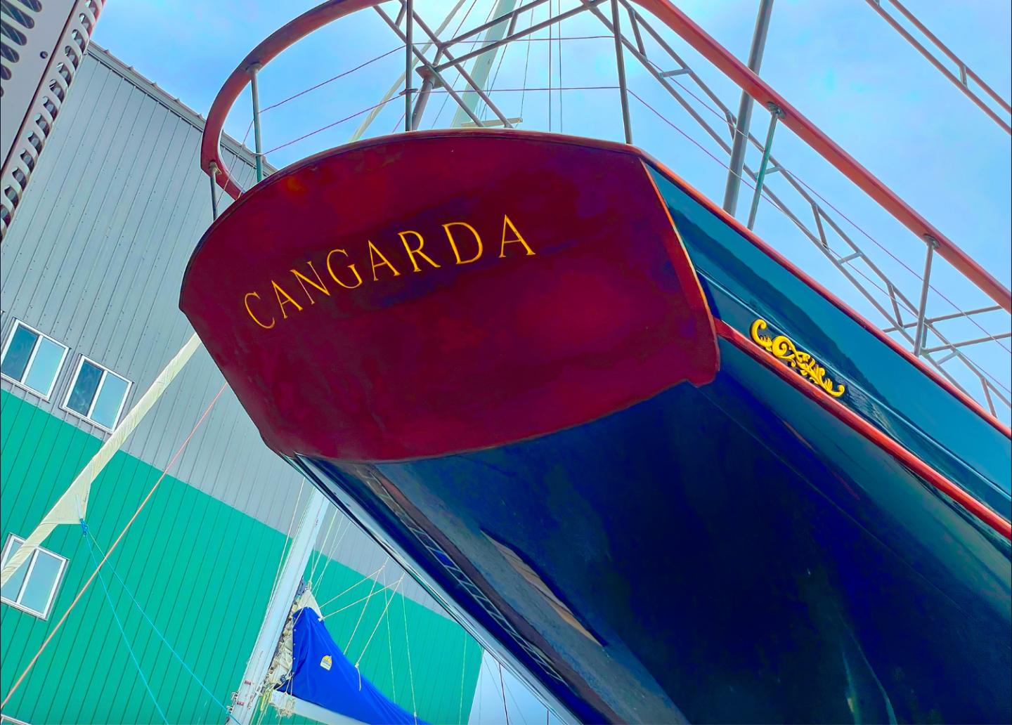
Bob, I don’t know but like you would be interested to find out. This is what I believe the rules are: The name and the hailing port must be displayed externally on the vessel, either on both sides of the hull or on the transom. The hailing port must include the place and a state, territory, or possession of the United States.
-
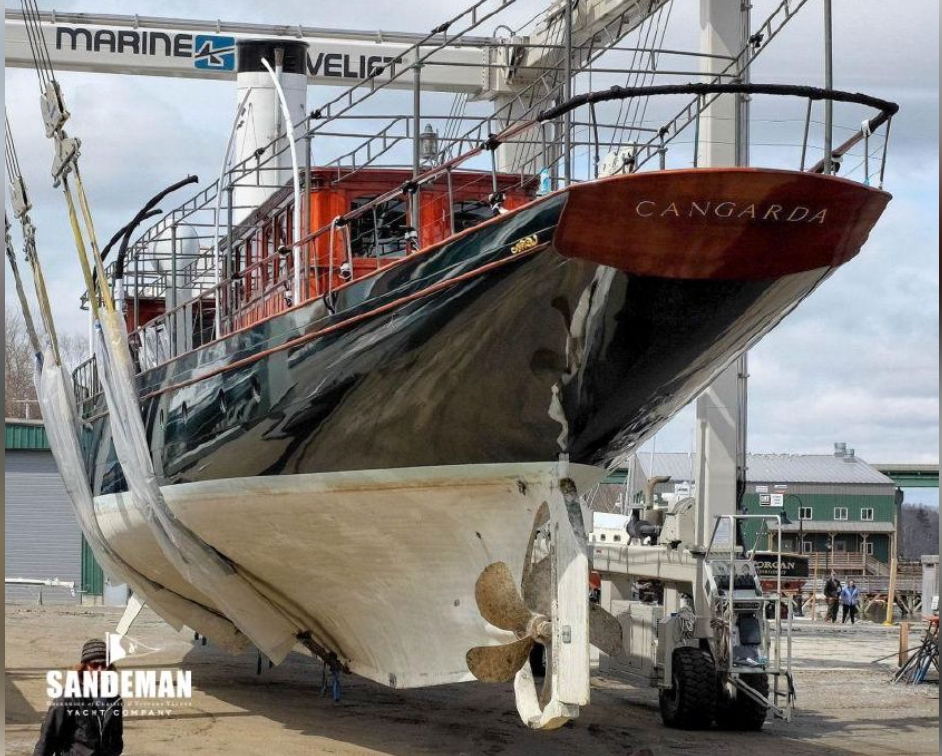
NRG Member 148 Location Belfast, Maine #2379 Posted Monday at 05:23 PM Keith, I got some more photos of Cangarda today. Slight rain and overcast. I put in a request to get aboard to take more photos, hope to hear back sometime today or tomorrow. Note that the discharge pipes are not symmetrical port to starboard.
-
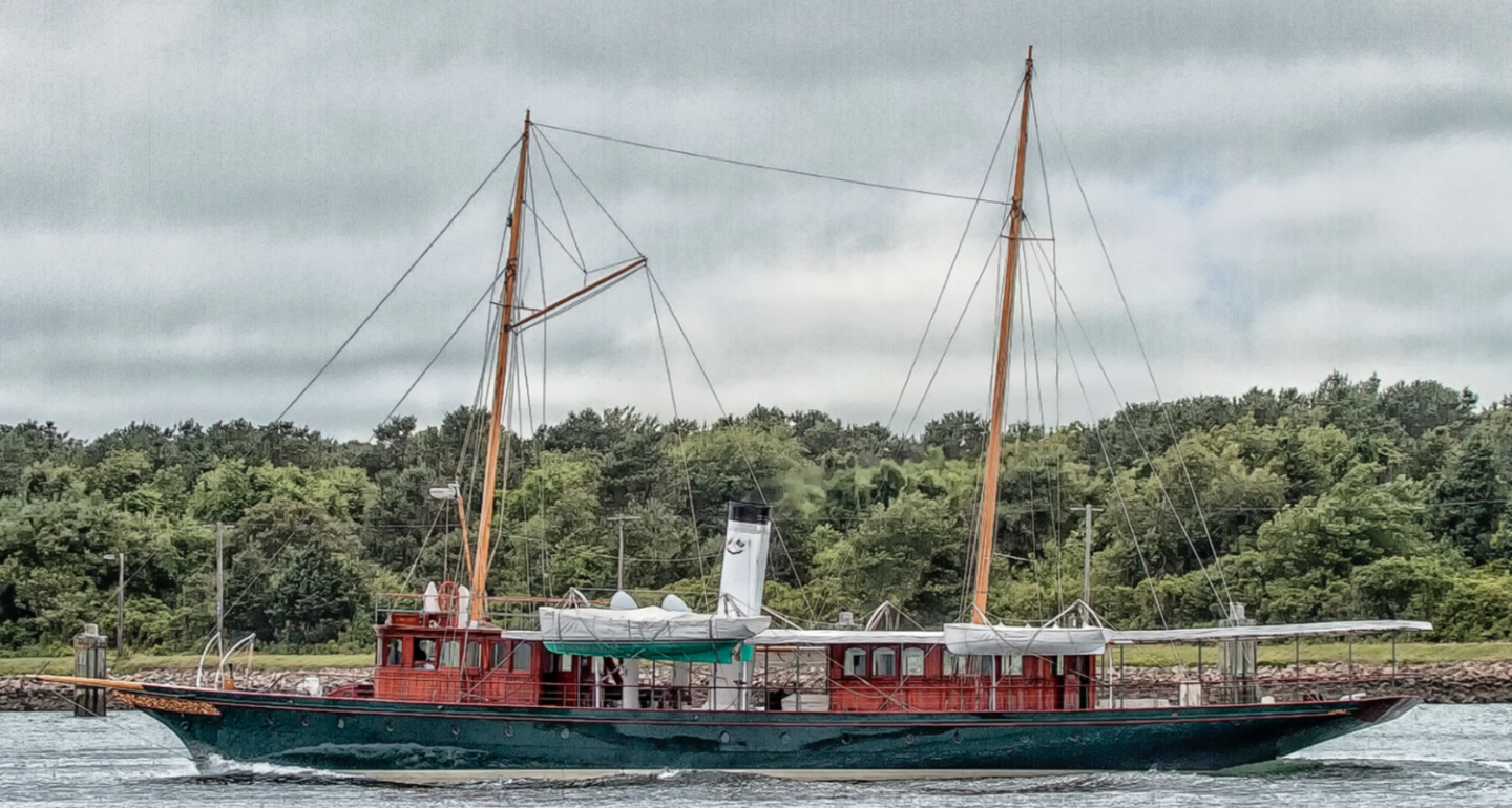
So this is the start of another build. Many of you will be aware this was coming because of the posts at the end of my now completed Germania Nova project. Rather than go into the history of Cangarda I will add a reference to a couple of documents which cover her history admirably. For many years I have admired the beauty of gentlemen's yachts built between the late Victorian period to the short reign Edward VIII (1880 - 1936). It seems to me this was a period where style and opulence over rode functionality and efficiency. They were designed to enchant the eye and not the purse and their sheer beauty was the aesthetic epitome of elegant ship design. Cangarda is the last American example of this unique type of vessel. As we all know getting the build information together for projects can be daunting and even when it does start coming together we all get the "how the hell am I going to reproduce that" moments. Lack of information and doubting my skills are my greatest barriers to making a start. Unfortunately once the information side comes together the excuse of inadequate skills just becomes a challenge and I find myself compelled to overcome. So here goes! Firstly I have to acknowledge some great people who have been ( and continue to be) instrumental in overcoming the information hurdle. I was reluctant to make a start on this build without a reasonable definition of the hull lines. A extensive internet search produced little to go on and I eventually decided that the only option was to approach Jeffrey Rutherford of Rutherford's Boat Shop inc. Rutherford's Boat Shop rebuilt Cangarda in the early 2000's and are primarily responsible for the wonderful restoration we see today. Not withstanding the challenges of running a business Jeff responded promptly to my "out of blue" email and facilitated the information that I needed. Many thanks to Jeff. Here I must also thank Andrew Davis of Tri Coastal Marine who provided the engineering expertise for Cangarda restoration project. Andrew supplied the hull lines and general arrangement drawings in PDF format. Many thanks Andy. Finally a special thank you to one of our own. I find that inevitably most photographers of beautiful vessels concentrate on the grand vistas while missing the intimate details. Videos can help as they catch the detail in passing but often they don't have the desired resolution. Video tours are better but often unavailable. The ideal solution is a visit to the ship but this isn't always possible. However MSW provides a wonderful network of very helpful people. Here I must make special mention of Rick310 who has gone well beyond the call of duty to photography all those details which make the model come to life. Thank you Rick for your past and ongoing efforts as the official photographer for the project. So a start is made. Here are some reference document for those of you interested in Cangarda's history. magadoma_cangarda.pdf rutherfordboats.com-resources-CYS2006_CANGARDA.pdf.webloc https://www.sandemanyachtcompany.co.uk/yacht/618/pusey-and-jones-126-ft-steam-yacht-19012009
-
Fantastic Rick, you are being tremendously helpful, l think I am going to have to dedicate this build to you. Such wonderful people at MSW. So much detail to see in the hull photographs it supports me in my decision to go for a very large scale.
-
Funny thing the english language. Very few writers choose all the right words and and punctuation all of the time. I tend to miss out words and punctuation and when I do get it right spell check usually replaces the key word with something else. It was much simpler when I used a dipping pen and ink. Al - yes that would put me off.
-
I found the whole debate fascinating, which probably means that I too am blessed with Shelton’s traits.😀
About us
Modelshipworld - Advancing Ship Modeling through Research
SSL Secured
Your security is important for us so this Website is SSL-Secured
NRG Mailing Address
Nautical Research Guild
237 South Lincoln Street
Westmont IL, 60559-1917
Model Ship World ® and the MSW logo are Registered Trademarks, and belong to the Nautical Research Guild (United States Patent and Trademark Office: No. 6,929,264 & No. 6,929,274, registered Dec. 20, 2022)
Helpful Links
About the NRG
If you enjoy building ship models that are historically accurate as well as beautiful, then The Nautical Research Guild (NRG) is just right for you.
The Guild is a non-profit educational organization whose mission is to “Advance Ship Modeling Through Research”. We provide support to our members in their efforts to raise the quality of their model ships.
The Nautical Research Guild has published our world-renowned quarterly magazine, The Nautical Research Journal, since 1955. The pages of the Journal are full of articles by accomplished ship modelers who show you how they create those exquisite details on their models, and by maritime historians who show you the correct details to build. The Journal is available in both print and digital editions. Go to the NRG web site (www.thenrg.org) to download a complimentary digital copy of the Journal. The NRG also publishes plan sets, books and compilations of back issues of the Journal and the former Ships in Scale and Model Ship Builder magazines.


