


dafi
-
Posts
2,297 -
Joined
-
Last visited
Content Type
Profiles
Forums
Gallery
Events
Posts posted by dafi
-
-
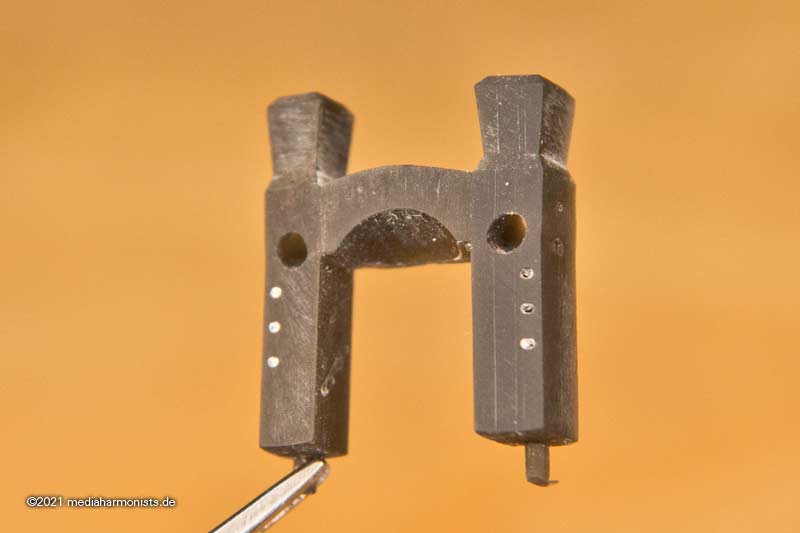
No idea either. Sure it represents the breech.
One more tip: If you assemble the carriages, have a look that the ejection marks point to the inside 🙂
XXXDAn
- Ian_Grant, Old Collingwood and Mexspur
-
 3
3
-
Dear Bill, I hope you do not mind that we get beyond your build log 🙂
For the above mentioned links, one has to click onto the arrow on the top right corner to go to the mentioned entry.
But there is nothing about Turner shown there. I think @Morgan mentioned something hehe in MSW.
The best interpretation so far imho is from Maik and to be found in our german forum:
https://www.segelschiffsmodellbau.com/t7042f1475-HMS-Victory-Spurensuche.html
https://www.segelschiffsmodellbau.com/t6980f1475-Turners-Deckszeichnungen-der-Victory-reloaded.html
https://www.segelschiffsmodellbau.com/t7001f1475-HMS-Victory-nach-Trafalgar-ein-letzter-Zeuge.html
You have to subscribe and you will find a "select language" button in the left bottom corner of the window. Automatic translation of course, but it gives the idea.
But now back to Bills wonderful build!
All the best Daniel
-
All perfect sirs 🙂
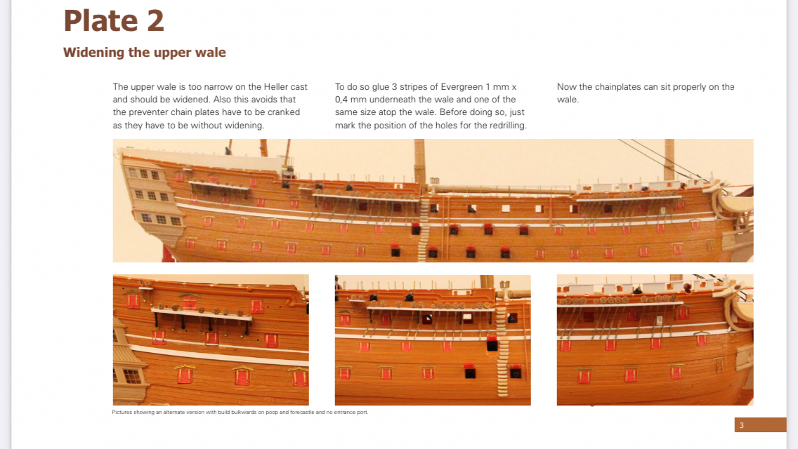
Just a small explanation: I used the three stripes of 0,4 mm x 1 mm as this is standard material and the 0,4 mm x 3 mm is a special size I will not use too often. And seeing the prizes of Evergreen ...
Also to come back to the build barricades on poop and forecastle: I discovered the footer on the instructions: "pictures showing an alternate version ..."
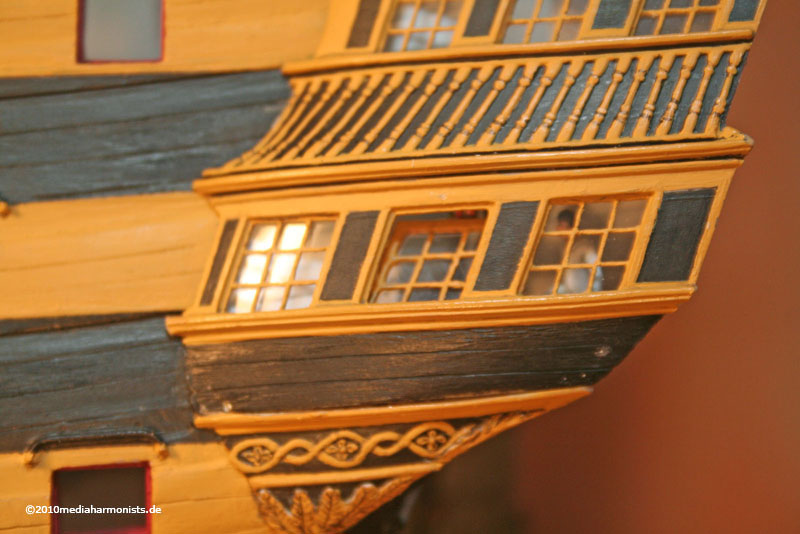
The part Bill was asking about is a wooden cover, some planks outside the hammock cranes, protecting them a bit more. This was standard by 1803, when the Vic came out of the repair. Also in this picture the forecastle bulwarks are risen, a detail that was also state of the art in 1803 and is documented nicely in Turners drawings.
All the best, Daniel
Here is some more detail about it:
-
55 minutes ago, Bill97 said:
Ok thanks gentlemen, especially you Daniel. I did not email you with the question because I thought I bugged you enough with my order! 😊
So the work I need to do is represented by the white lines in the photo? I was so confused. I was thinking I needed to build up the height of the bow. In the picture there appears to be a light cream color stripe on top the hull at the stern end and maybe even at the front. This cream color stripe is what I was thinking I needed to fabricate and attach to the top edge of the hull. I am guessing now that the cream color object is just something in the photo? It even blocks the view of the bottom of the mizzenmast. What is that?
Hello Bill do not worry to ask. But its always better to do like on a place like here as others can participate too - or even give you the right answer already before i find it 🙂
Yes you are right, it is about the thin and larger white lines in between the middle and upper gun deck ports. Easy to be done and with a good effect. Thank you for the question, I now can precise the instructions a bit 🙂
All the best, Daniel
-
Thank you sirs for all this ongoing discussion.
And you are right. The upper wale is to narrow in the mold so it could/should be enlarged a bit on the bottom and on the top. It also facilitates to fix the preventer chains.
As I always try out results of new research there is in the same picture the risen forecastle bulwarks - and also some on the poop deck. I already have several hulls for different purposes floating around, so I sometimes have to combine the tasks. Originally this picture was set for another context in one of the other pages, showing Portsmouth and a possible version of Trafalgar. Sorry if this confused you lot. As the research advances always new hints or even evidences pop up, and I strongly do believe we will never be able to build a "100% accurate" 1805 Victory. So all work on the Vic always will be "state of the research".
All instructions are updated from time to time to represent all the feedback that I get from you guys out there and also the my own new enlightments to assure you some good quality modeling time and best results 🙂
All the best, Daniel
PS @Ian_Grant Wonderful model!
-
On 5/14/2021 at 10:50 PM, Bill97 said:
My initial internal debate is the process used to paint the hull, especially the stern? I think by far the design of the stern and the paint scheme is so distinctive on the Victory. You see it you know it is the Victory! So beautiful! If you are now building, or did in the past, what was your method to apply the black and yellow ochre.
Within the next days there will be available the assembly instructions for the resin parts, also including some hints for the painting 🙂
As usual, it got more detailed than planned, but the whole lot for anchors, side entry and the stern is already now 26 pages full of technics and hints, and some more still coming as I have to finish the painting to shoot the fitting pictures 🙂
The german version is almost finished and the translations will come soon afterwards.
All the best, DAniel
-
Regarding your question on plate 6: It depends how far you feel like going.
Best effect for the new hinges is of course if the ports are closed. If opened they officially should be a tad up more then horizontal, so the hinges can be seen clearly but even more the eyebolts. But this also means extra fiddly work. If the lids are up more than 45° - in reality not to be done as for lanyard reasons - then of course no one sees the difference.
All the best, Daniel
-
Hello Bill,
sorry for the delay, I was not in the office for a while. Should be there today and tomorrow and will have a look for your order 🙂
All the best, Daniel
-
42 minutes ago, Hubac's Historian said:
Okay, Ian - what did you do for thread to rig the model? Did you purchase someone else’s scale rope? Make your own scale rope?
Syren got out of the rope making business. I’m debating whether to lay-up my own line.
Just do so 🙂 Same scale as my Vic so you can copy and not too difficult and great effect with the full variety of all needed sizes. Most rope shops have sizes optimized for larger scales.
XXXDAn
-
Dear Sirs, thank you for all the interesting discussion here and the very nice comments!
Did not have too much time lately as for real life purposes, but it was a joy to discover the discussion here. Thank you all for that!
Yes it is right. Of course one can leave the brass blank, especially wooden ship builder do this by choice sometimes. But the main reason for the parts are to provide extra or better detail than the kit can offer. When I started the kit some years ago, I had to learn to solder to replace the chains by custom made ones out of brass wire. Time consuming but great effect and well worth it. Actually the second picture that @Ian_Grant shows in #59 are real "hand made" ones, before I did the etch parts. Thanks for showing the old pix, Ian, one nicely sees the difference. But after the first set one only thinks - been there, done that. So laziness from my side was to help developing the etch chains.
Let me put it straight: the Heller kit is one of the finest available. In the days it was released - some 50 years+ afaik - it was state of the art. The idea of faking the dead eyes was - seen by those days - magnificent. Only times have changed and we model makers have risen our standards. Also the plastic moulding has limitations as for thicknesses in both ways. Details smaller than 0,5 mm were difficult and thicknesses over 1,5 mm create sink marks.
For the missing thickness one can double the material with sheet as shown here nicely with the gun ports. All details smaller than 0,5 mm are a wonderful subject for etch parts.
Also in this aspect we have improved a lot. We expect today many details, we did not bother 2 decades ago.
And the last thing is that the research is far beyond the knowledge of the days that the kit was created. Side entry or not, stern davits, side davits and knowledge of many other things has changed. So we can take a chance to adjust a bit. If one ever wondered over the strange binnacle displayed by the kit, a matching one was on display in Portsmouth in the 1950ies 😮
So Bill, great start here and to all of you: Have fun and enjoy modeling!
All the best, Daniel
- mtaylor, europapete, Ian_Grant and 1 other
-
4
-
Thank you Sirs 🙂
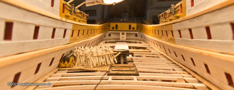
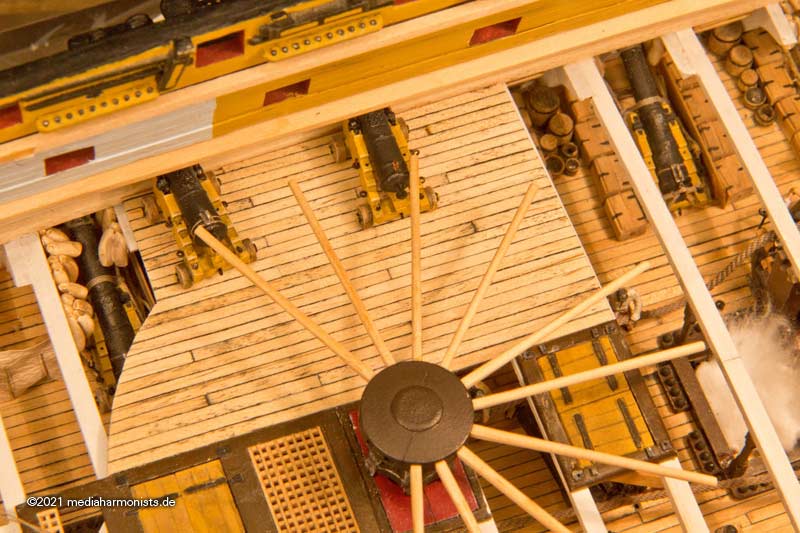
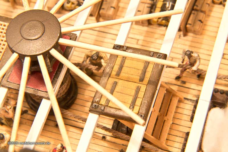
Once you take a look at the whole thing manned, you immediately see how tight it is inside and out.
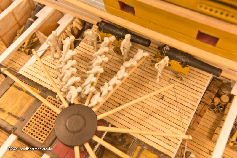
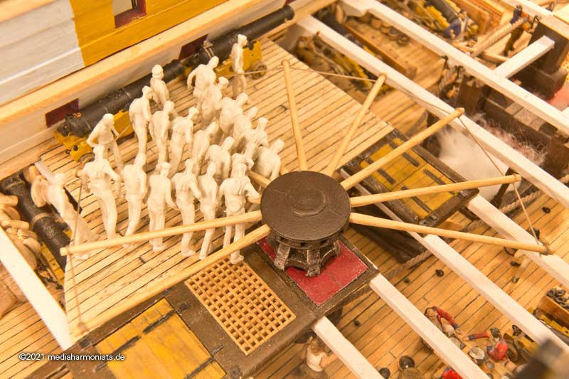
Seen from above, it's clear that even the diving away under the swifter and running back that some people assume will be somewhat difficult here, and could quickly throw the others out of rhythm. If, while the bars are being inserted, the rest of the crew is heaving the guns over, a smooth work flow is guaranteed while turning. I'm not talking about work safety here but of a smooth rotating flow 🙂
The Swifter was led by a notch at the end of the bars. Whether there was only ever a knot in front and behind the bar or whether it was secured for example by a half hitch I will still find out.
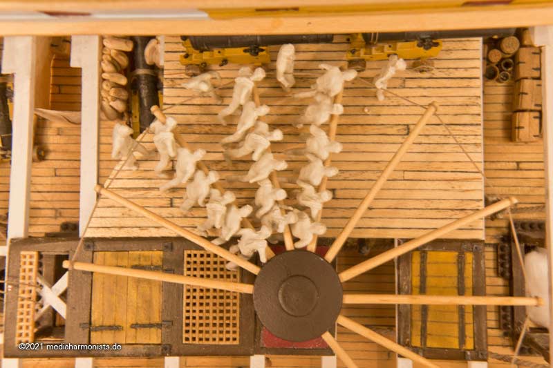
Interesting also in the lower perspective. Jumping over the guns wasn't possible there either, the deck beams were only a few centimeters above the
heads, and the outer sailors probably have to watch out with the hanging knees anyway ...
Here you can see it nicely what I mean, at 0:15 - This action combined with deck beams one would then hear a rhythmic "Klock" when hard wood (sailor's thick head) hits hard wood (deck beams) ...
Simply delightful to see.
And for the naval officers in the boats finally a possibility to look unpunished under skirts, as the girls up there come along on the spar ...
It remains exciting 🙂
XXXDAn
-
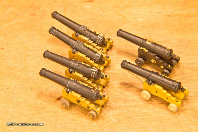
The days I have again made some guns, 2 horizontal, two lashed upwards, one with etched parts but unpainted and an old one painted but without etch parts.
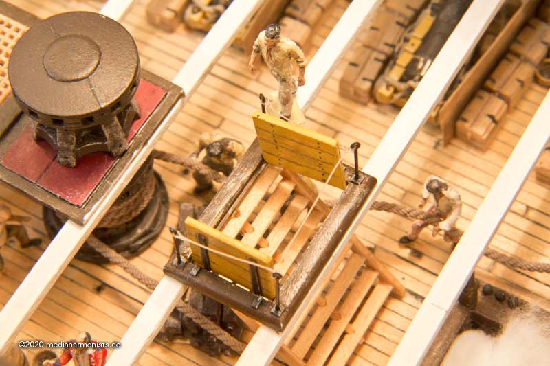
Then some shipwrights came by and installed a makeshift deck in the aft capstan area. The caulkers came also immediately and left a giant mess with their tow and tar ...
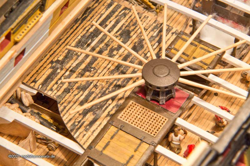
I'll spare you the curses of the sailors who had to clear the deck, they were terrible, but afterwards the whole thing looked passable again.
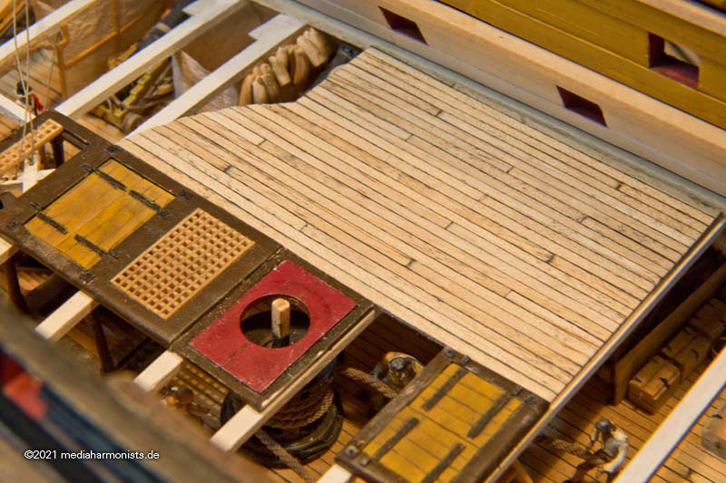
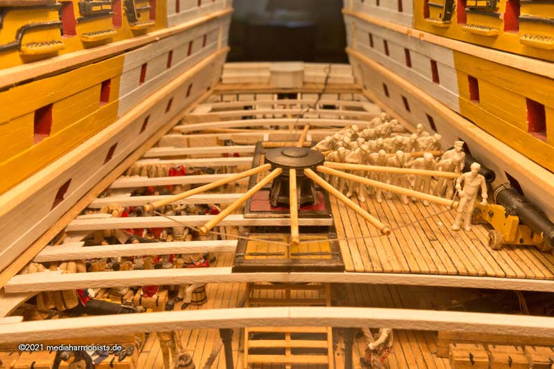
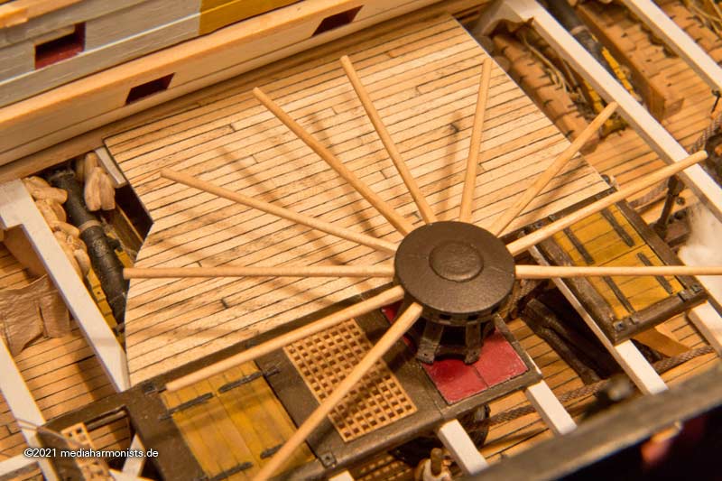
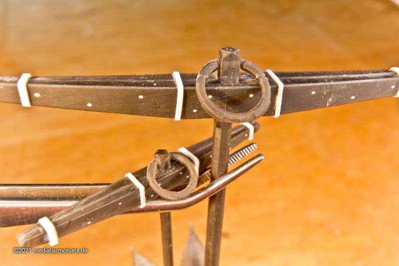
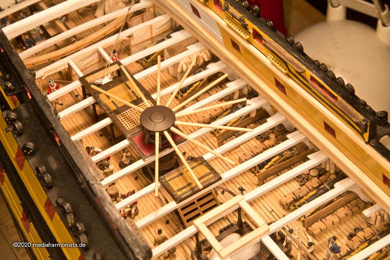
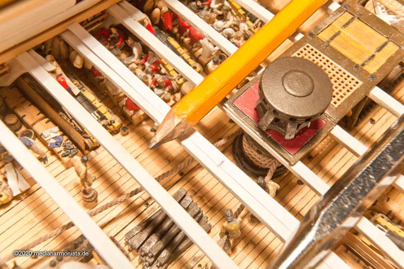
Here is shown the area covered by the capstan bars´ radius.
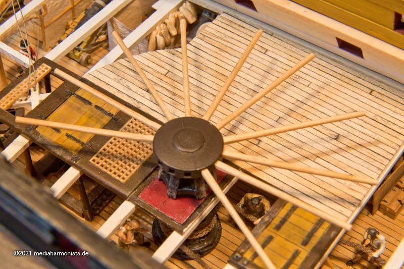
And this is where the guns come into play: in their normal position, they are simply in the way of the spars. But stowed lengthwise on the ship's side, it looks much more spill user-friendly.
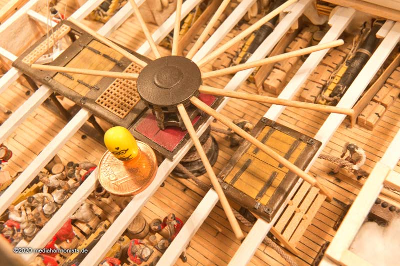
Here in the lashed position with the muzzle on top, without chair and the coin.
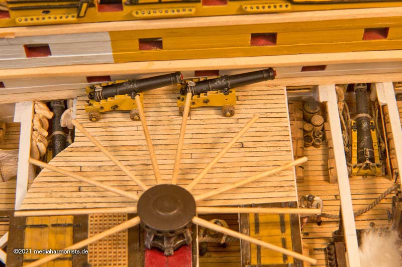
Here with the barrel in the horizontal position, chair and coin inserted.
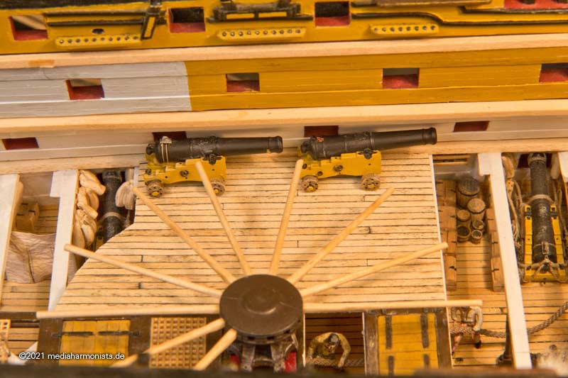
And just to check: even when run out, it's not enough for a decent bar radius.
It remains exciting 🙂
XXXDAn
-
For the highlight figures like officers I use more care and putty but also lot of paper as for the frog tails, belts and other stuff. For the common seamen I usually just scratch off all modern items as pockets, watches and zips 🙂 The rest is done by then paint.
The plastic is a good one, just like the kit itself, so no problem in putting putty and paint, not like the airfix 1/72 figures that are done in a soft plastic.
XXXDAn
-
-
-
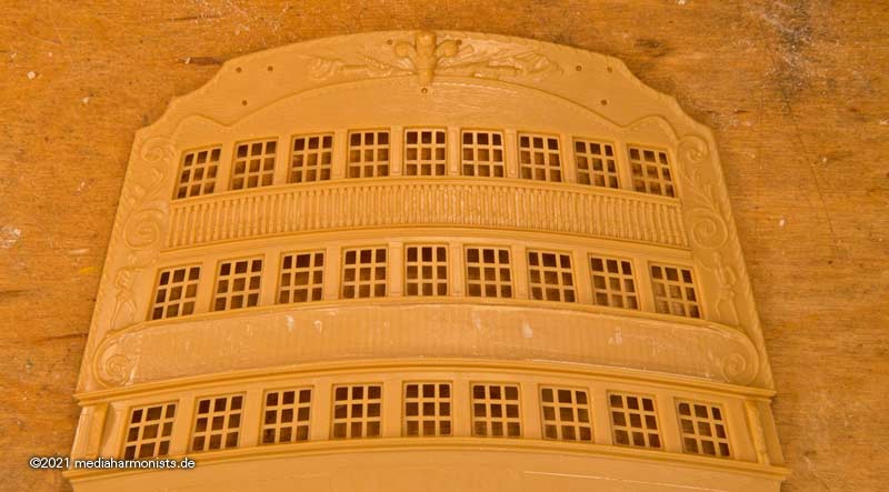
Of course it tickled my fingers and was already overdue, but finally I could slap some colour on the pilasters 🙂
First some ochre, then a bit of heavily thinned ink for the depths and finally some white brushed over it for the heights, and then the whole thing on a black background - oh how cool 😎
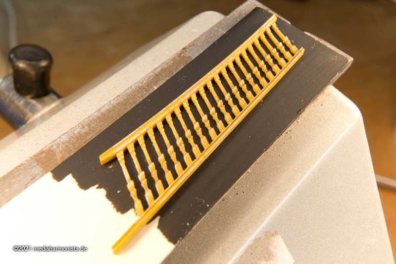
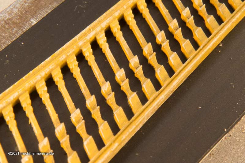
This is the area as I did it with the original part of the kit to compare. Also the form of the pilsters now is correct 🙂
-
To once again contradict all those who think that the printer is the solution to all trying and an easy way to the part ...
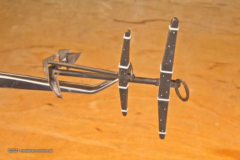
In the meantime I have converted some of my resin castings into printed parts. The form is just a bit more sharp. Here are the timber heads.
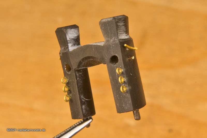
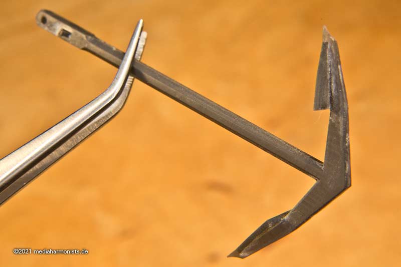
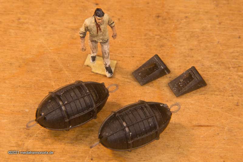
And the anchors now have their shape according to Steel and other contemporary sources. The edge between the shaft and arm is sharp by now and not as rounded as in modern sources as AOTS and others.
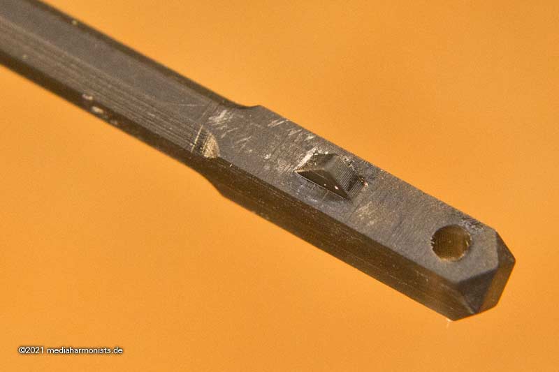
The shaft has the nut in the area of its head, the stock has the matching counterpart.
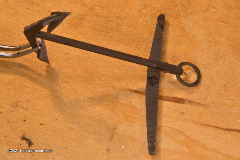
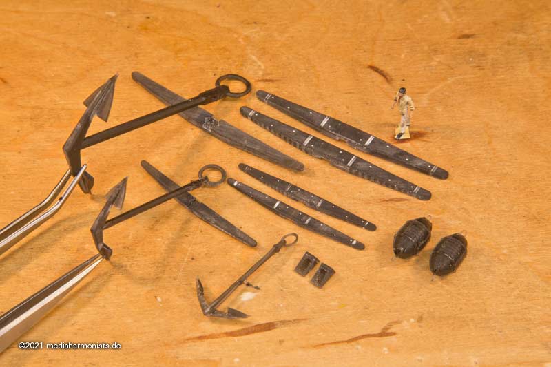
I was particularly taken with the small kegde anchor. It was probably stowed on the aft starboard best bower.
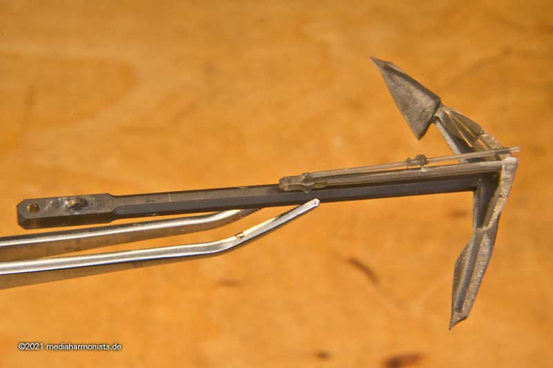
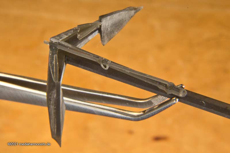
With the pin lock and the pin securing line.
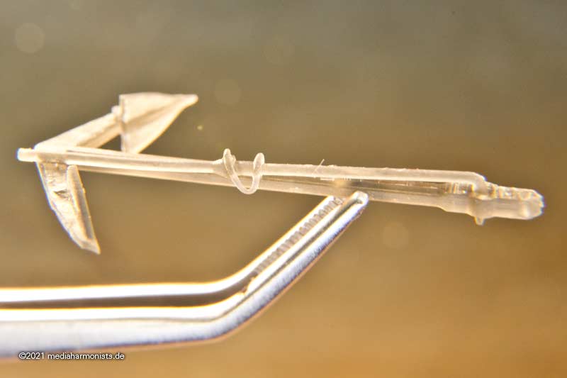
And a very, very small detail after Steel: The anti-slip device of the shaft. Simply split the end of the arm and bend it open. Can be pressed together again for repair purposes and then again fits through the hole 🙂
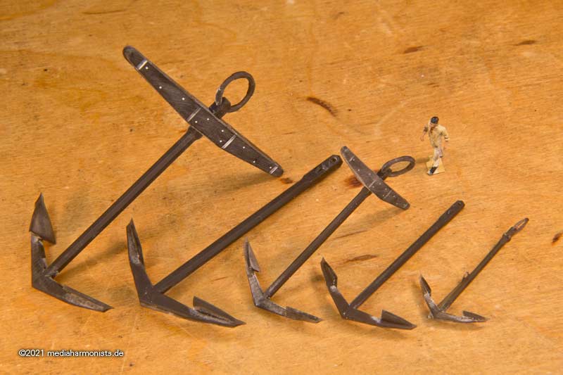
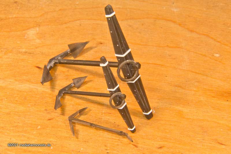
Still missing the family pictures of the anchors 🙂
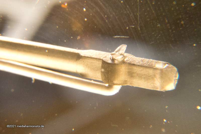
Stowing of the Stream Anchor on the aft port Best Bower.
The head of the shaft with its characteristic bevelled corners and the indicated woolings of the rings.
And anchor buoys and anchor shoes were also redone.
XXXDAn
- mtaylor, mort stoll, rybakov and 7 others
-
10
-
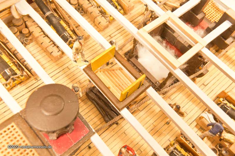
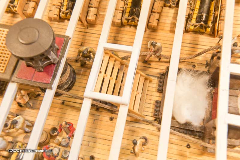
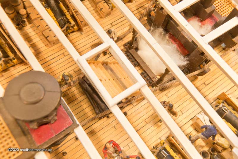
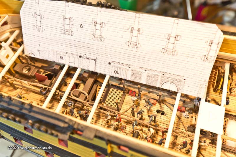
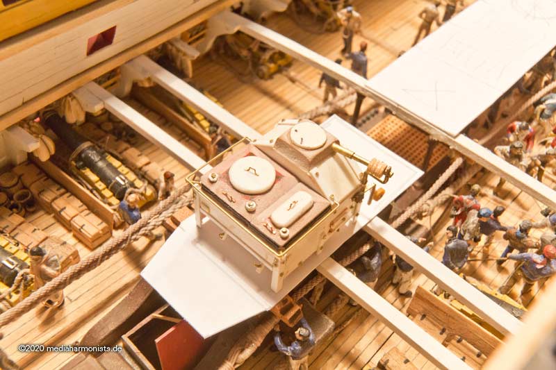
After this short side walk, I continued on the middle deck....
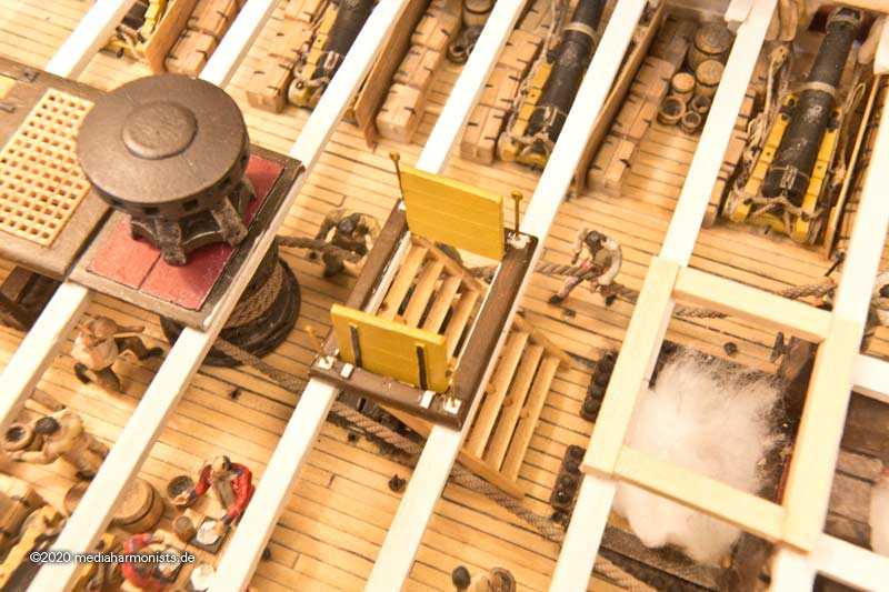
Now with all parts, so also etching supports for the fall protection.
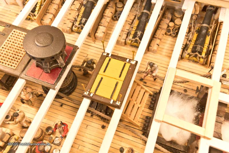
Then with paper strips determining center and left and right edges ...
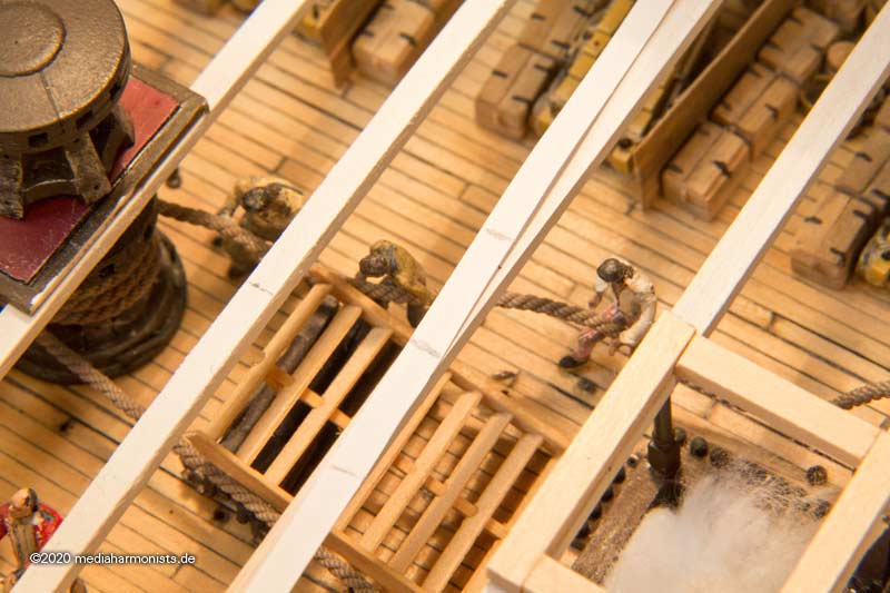
... aging parts and glueing the coaming in place.
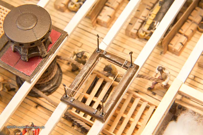
Note that the staircase will not fit through the top because of the rabbet, so it must be pulled up from below with thread ...
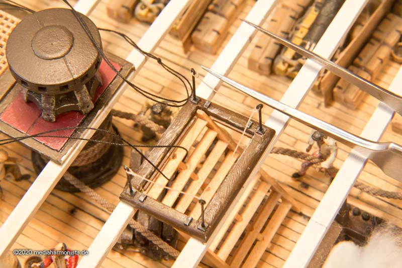
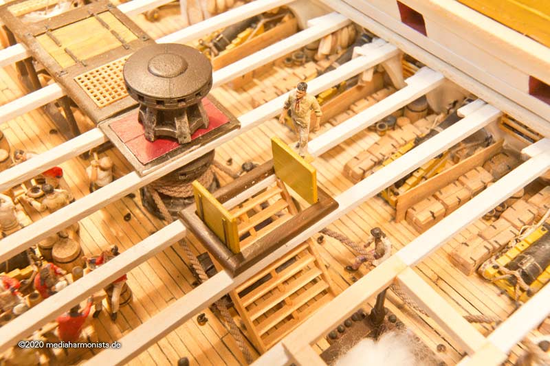
... flaps inserted ...
... and the thread pulled with surgical precision and ready the open version 🙂
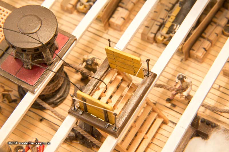
Then closed the flaps, removed the supports and inserted the capstan.
Here is the whole thing then finally with my small scaling companion.
And in the overview 🙂
All the best, Daniel
-
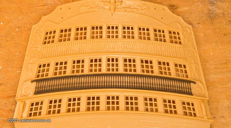
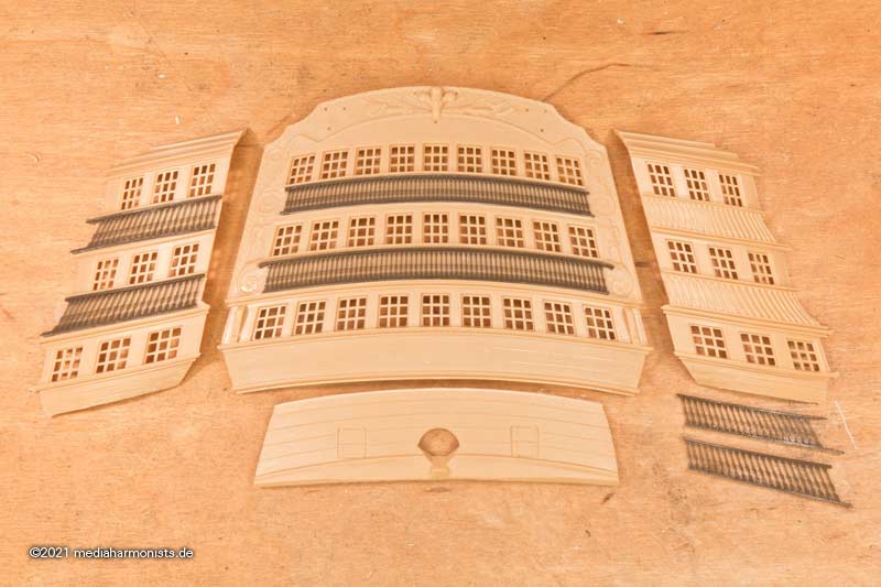
Once again the typical Dafinist shift of the scene of crime. Since I know that I soon will need another stern for the Vic, I dared to tackle an issue that I could only solve by clever colouring when I created the last one.
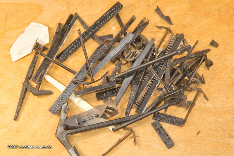
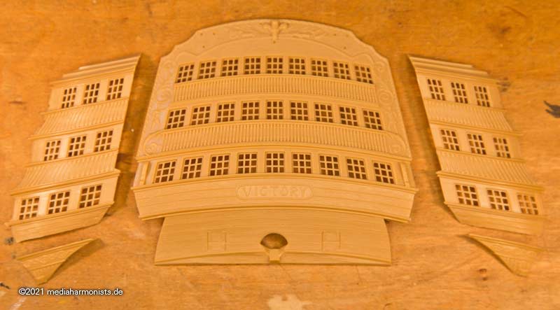
But one after the other. Here are the parts of the kit as they fell out of their box.
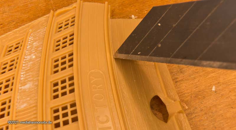
First the courageous cut to separate the lower part, which makes the assembly immensely easier later.
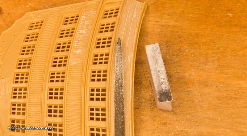
Then I filed out the name cartouche and levelled it with a matching sanding block. The wood structure also went to wood-structure-heaven.
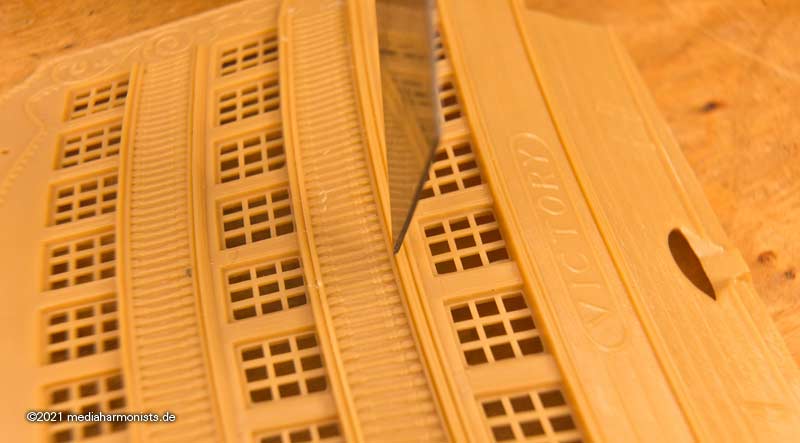
Then a cut between the profiles above the pilasters ...
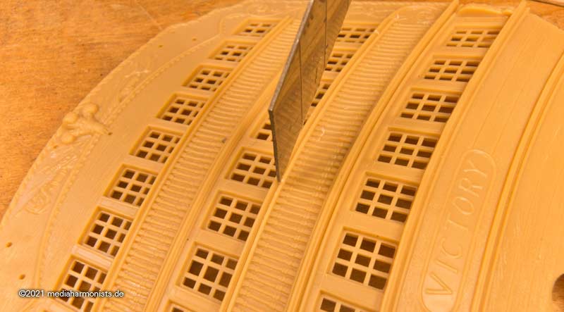
... and one below.
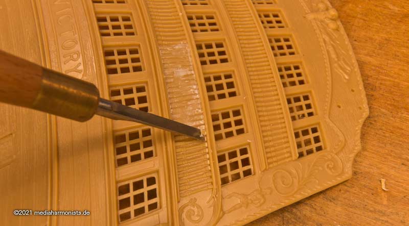
Then using the chisel to discard of the old pilasters.
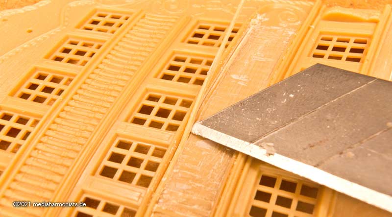
Then trimmed the profile from the top side ...
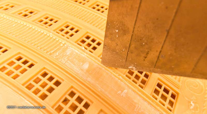
... and cut it so deeply from below that it came out in one piece.
And everything smoothed out with the small files and the matching sanding blocks 🙂
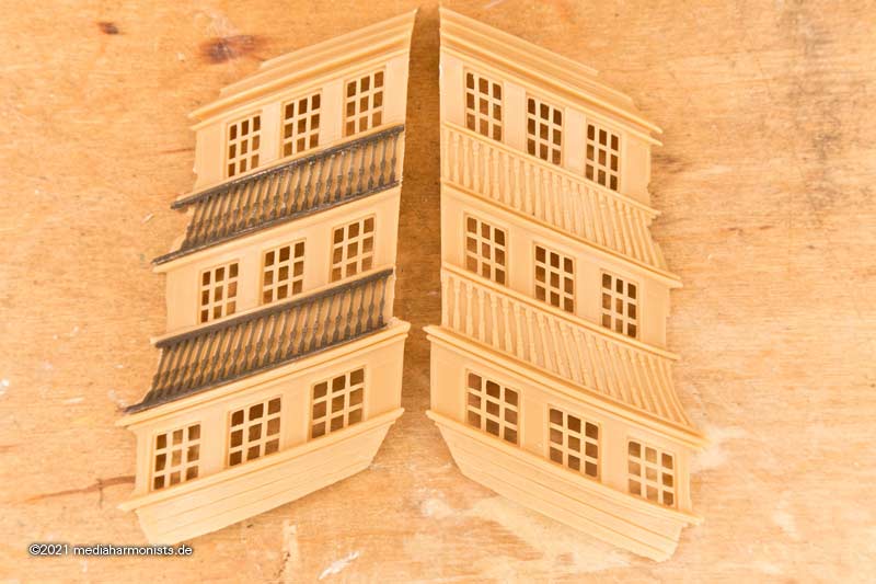
And then *tata* the new pilasters came out of the hat 🙂
And in situ.
Fits 🙂
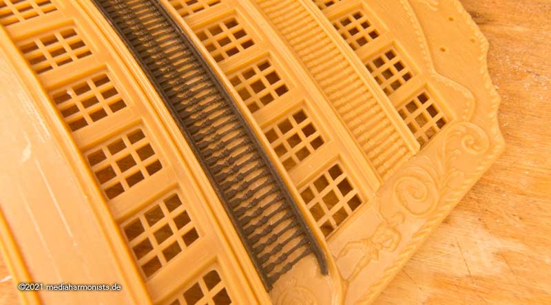
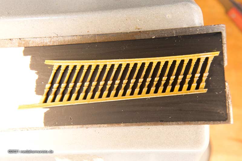
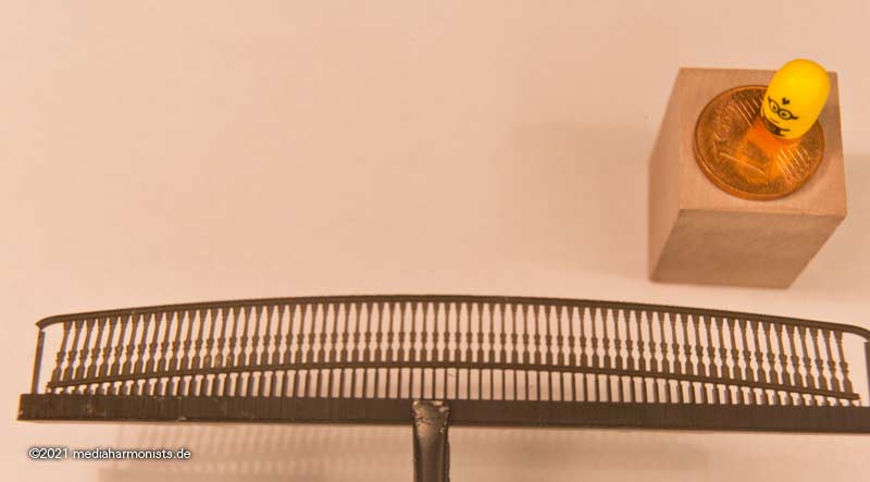
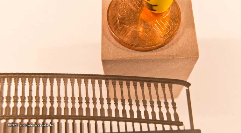
I also re-pilastered the side galleries. Here the comparison with the originals of the kit.
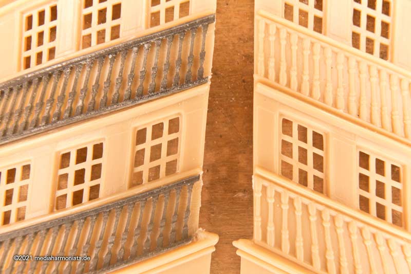
And the parts are so fine that I only saw in the super macro that the volutes of the pilasters had slipped up a bit during the first adjustment, or better saying that the upper volutes had not moved down with the rest when they were shortened ...
So I went back to the computer, moved the volutes in the 6 panels and reprinted them ...
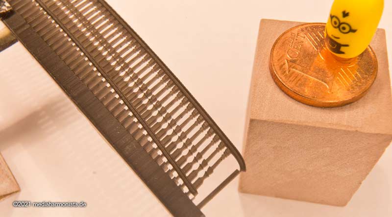
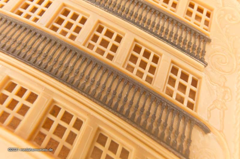
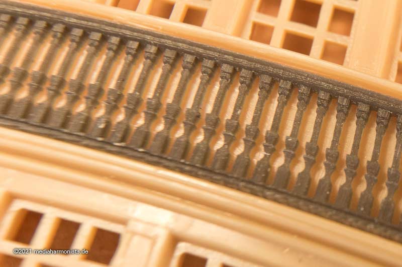
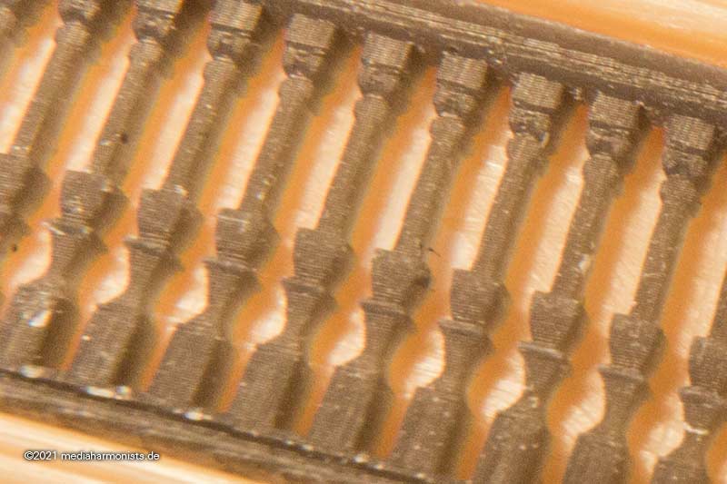
So, as a little titbit, the following picture. I wanted to know if this resin can be moulded under heat like the cast resin. And I was surprised, a short dip in hot water and you can almost tie a knot in the pilaster ladder. Honestly - I swear!
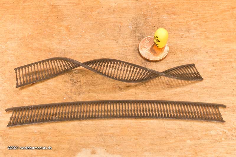
The reason for this action is that the kit parts are getting on in years and have plenty of sink marks in the area of the pilasters that are very difficult to iron out. But admittedly, it also looks nicer. I am already looking forward to do the the painting.
This is how it will look like.
Ok, and the printer is already running, more pictures soon.
XXXDAn
-
-
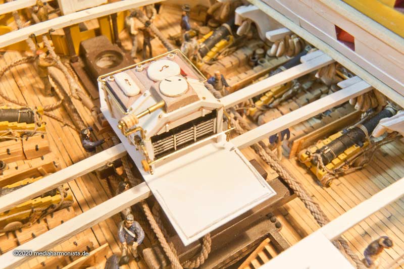
Ok, looks a bit better now 🙂
The sailers will be able to pass in between the flaps and do not have to jump them 😉
Now the support fold in the coaming, so that the flaps do not swing down, the plug holes for the iron corner posts of the guardrail, the stairs correctly aligned and good it will be.
🙂
XXXDAn
-
Why I always make so many test installations and pictures of it? Because sometimes I'm just stupid ...
Test fit of the companionway: coaming and stairs
- check - fits! Other side ...
- check - fits! Other side ...
- check - fits! Door flaps inserted, since the companionway is below the radius of the capstan bars ...
- check - fiiiiiiiiiiiiiieeeeeeeehhhhhhh...
Crap, find the mistake ...
GRRRRRRR!!!!!
XXXDAn
-
Hello Raymond, these are Preiser 74090. Heavily modified 🙂
XXXDAn
-
Thanks for the Likes gentlemen.
In the meantime, it has turned out that I have a nice challenge as I had only sketched out all the inner structures at the beginning of furbishing the lower gun deck and was that I was only going by sight ...
But as soon as one has to handle reference or chain dimensions, it becomes tricky ...
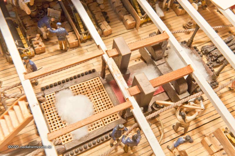
The mast partners and carlings of the main cargo hatch had to be moved several times until they finally fitted. And the deck beam cemented in so tightly that it was too difficult to replace it for a fresh one without scars ...
So first I had to define reference points for further work. You can't get in there any more with a caliper or a measuring compass.
Therefore, a thin strip of paper with some excess length placed on the beam, one side to the stop and something sharp pressed into the bend edge of the excess on the other side. Thus the respective length was fast determined. Then fold the strip in half and you have the exact center. Put it back on the beam and mark the middle spot. This quickly determines the center line of the deck.
Or, as with the hatch, place a piece of paper on top and mark the width with a scalpel. Hatch dimension quickly and accurately determined.
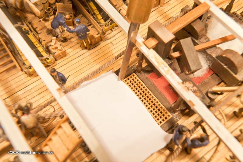
Fortunately I was able to clean up the messed deck beams, uffz!
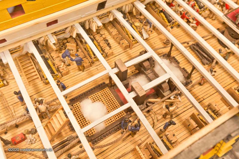
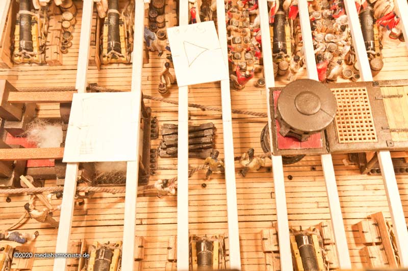
Then the sequence of hatches were determined.
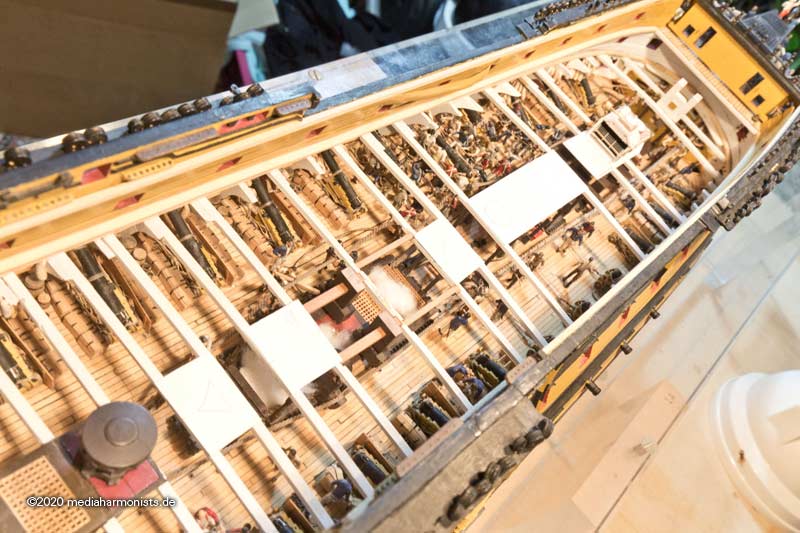
And also the Brodie stove has finally a prospect of a home 🙂
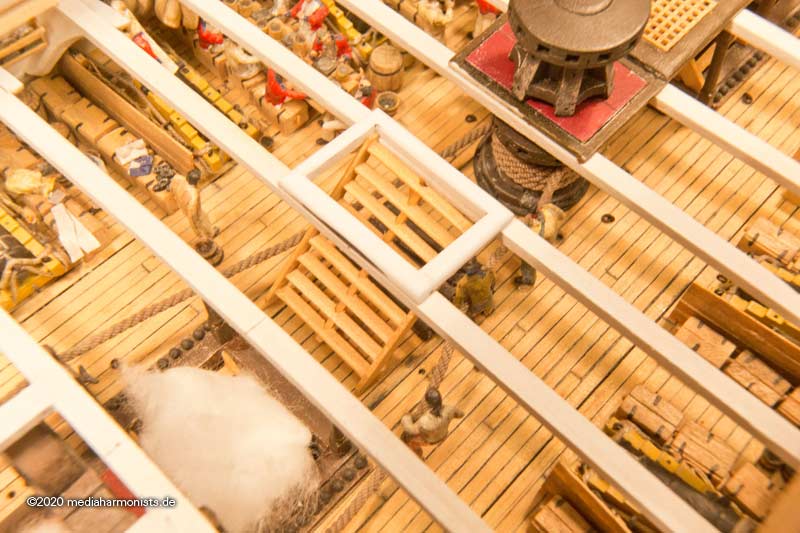
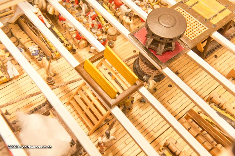
Then started working my way forward starting at the back capstan. As to be expected, there's a second companionway in the way of the capstan bars.
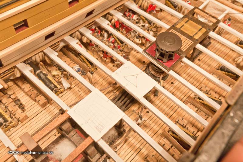
Marking the place of the companionway was useful, when I took it away it turned out that the removed deck stanchions from the lower deck batterie were stored right where the stairs is coming down.
So the stanchions were to be turned 90° and placed under the stairs.
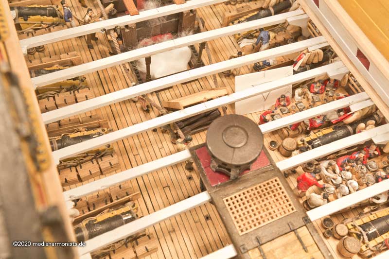
It's looking better already.
XXXDAn


HMS Victory by Bill97 - FINISHED - Heller - 1/100 - PLASTIC
in - Kit build logs for subjects built from 1751 - 1800
Posted
Of course I will. See it as luck or a curse 😉
One remark: It is a pleasure to help. Still it is your build and if ever I say too much please give a sign.
XXXDAn