


dafi
-
Posts
2,292 -
Joined
-
Last visited
Content Type
Profiles
Forums
Gallery
Events
Posts posted by dafi
-
-
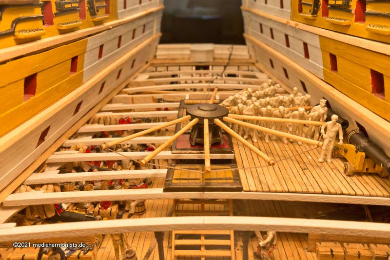
As for the wooden and metal parts of the capstans there are many sources of the different solutions being used considering the time of the build or repair.
More obscure to me is the human factor, how were they exactly manned, better saying what was the right pushing position?
 On 6/1/2021 at 9:45 PM, druxey said:
Nice demonstration, dafi. If you are planning on actually manning the capstan in your model, remember that they gripped the bars thumbs upward and palms towards them. (This was to avoid broken forearms should the capstan kick back.) So often the wrong grip is shown, like pushing a baby stroller or bike.
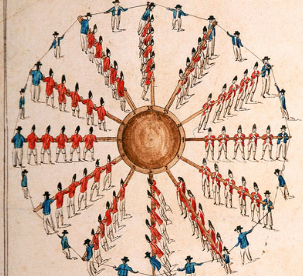
On 6/1/2021 at 11:39 PM, Bob Cleek said:... which was the most practical posture, given that they often put their chest into it to push the bar. Oddly, though, the contemporary pictorial record frequently depicts seamen carelessly pushing the bars with their hands. Perhaps this was a casual approach used to take up a slack cable before the real work began.
The guy on the right in the black cap is definitely a slacker, but then again, there's nothing on the drum!

The men to the left are doing it right. The men to the right aren't. Likely "artistic license" in this engraving.

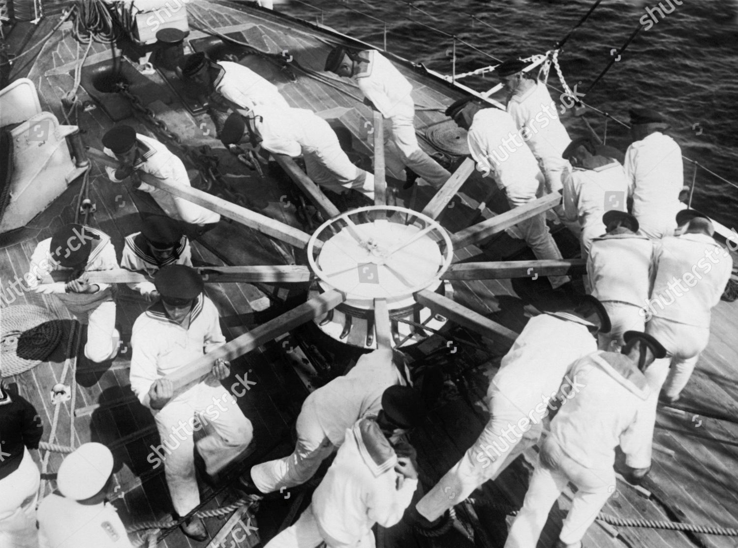
It seems the Finnish Navy did things differently, but there doesn't appear to be anything on the drum in this apparently posed photo. I mean, really, who mans a capstan in their dress blues?
Doing it right, but again, everybody's in their Class A's and this steam screw vessel appears underway at sea with white-painted anchor chain secured, clean and Bristol fashion, so what are they hauling, anyway?
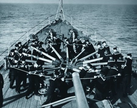
Germans, correctly putting their backs into it like they actually might be doing some real work.
The image one usually has in the head is that the man stands behind the bar and has the arms stretched, like in the first pictures, if properly done the thumps upwards together with the other fingers.
On the last two pictures the men are not pushing with the arms but with the chest, having the arms - sometimes even crossed - in the front of the bar. The second version is very much to be seen by images of the Imperial German Navy, in english pictures (graphics and photos) the long arm is more common.
Now the RMG collection finally provided a high resolution scan of "Hoisting anchor and stowing the cable" PAI5027 and in having a good look I believe that the marines tend to push the bar with the chest and have the arms in the front of the bar.
Could this be correct? Are there any objections against this use of the manpower?
All the best, Daniel
- Keith Black, mtaylor and bruce d
-
 3
3
-
-
Here the smaller version on the ship yard of the Skellig in Douarnenez in France.
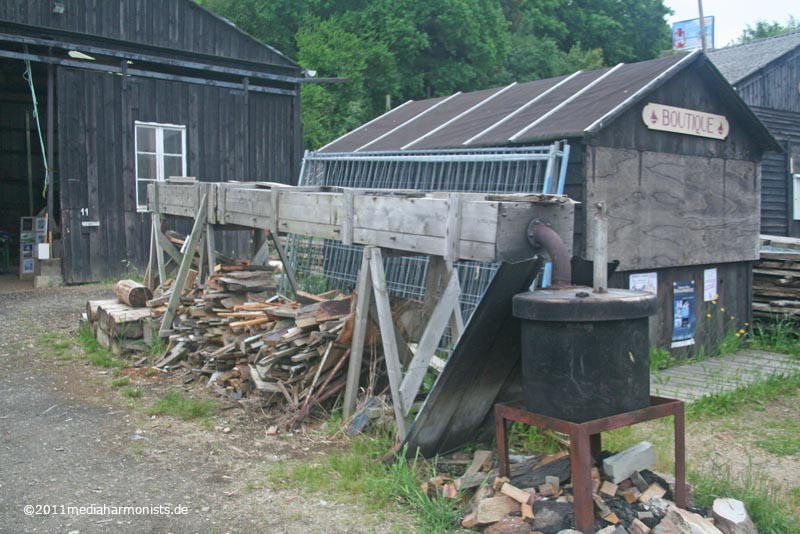

Let the plank steam for 1.5 hours, then be fast as you only have about 2 minutes to put the plank on 🙂
As after the first bending the planks can´t be put into the oven again as for the curve, it had to fit on the first go.And this is what they did there
More here:
It is in German but the automatic translator can be activated on the left bottom corner "Sprache wählen"
All the best, Daniel
-
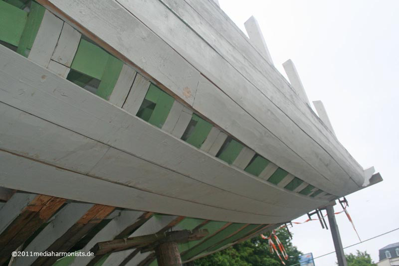
The shrinking problem and your tolerances are still much better than the correctness of the hull 🙂
Your side pockets look to fit better than the original ones from Heller!
As these parts are still made by hand* and not CAD they bear a lot of "off-measures". I think it is easier to go the classical modelers way with sanding and putty to make the parts fit. And by what I see the fit is already great seen this high complexity of the hull in these areas 🙂
XXXDAn
*This is not a moaning as doing these parts was state of the art when the kit came out. Those toolmakers did a marvelous job!
-
The board underneath the hammock cranes from teh forecastle is in deed an ectrapart mabe out of 0,5 mm sheet material 🙂
It protects the hammocks a bit from the spray fom the bow.
Wonderful job you are doing. all the best, Daniel
-
Illustrator and Cinema as for the rest.
XXXDAn
-
Actually I do not bother too much about it 🙂
First they are not appearent with the naked eye,
second the paint is usually filling these steps up easily as they are that tiny,
third I could easily sand or scratch them off if they proove calling attention,
and possibly last I always turn the parts in a way, so that they are not in prominent places.
XXXDAn
-
I already mentioned the next steps, now the next step was the rest of the entry port. Here, too, it is wonderful to see what else is still possible 🙂
But first define the size correctly and I realised that most entry ports on models are a bit too small, because they mostly align on the top edge with the gun ports besides. So I added a little more air at the top ...
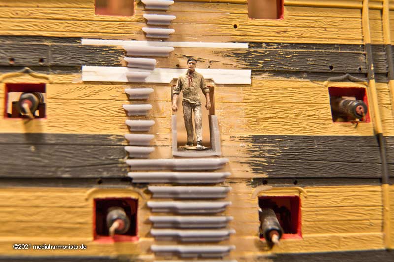
... and provide them with a frame for the passage.
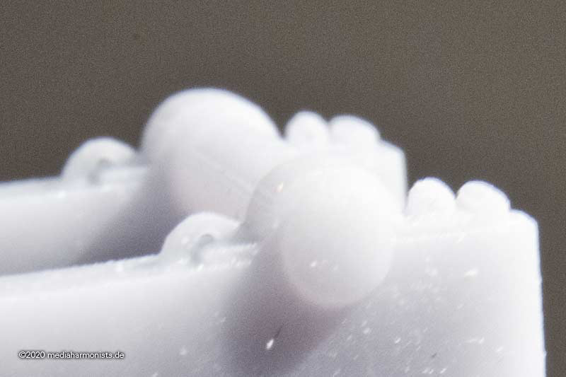
The scrollwork is presenting itself beautifully, note them in comparison with my epidermal ridges!
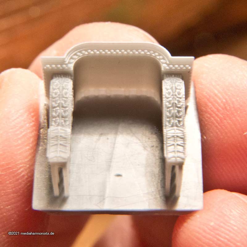
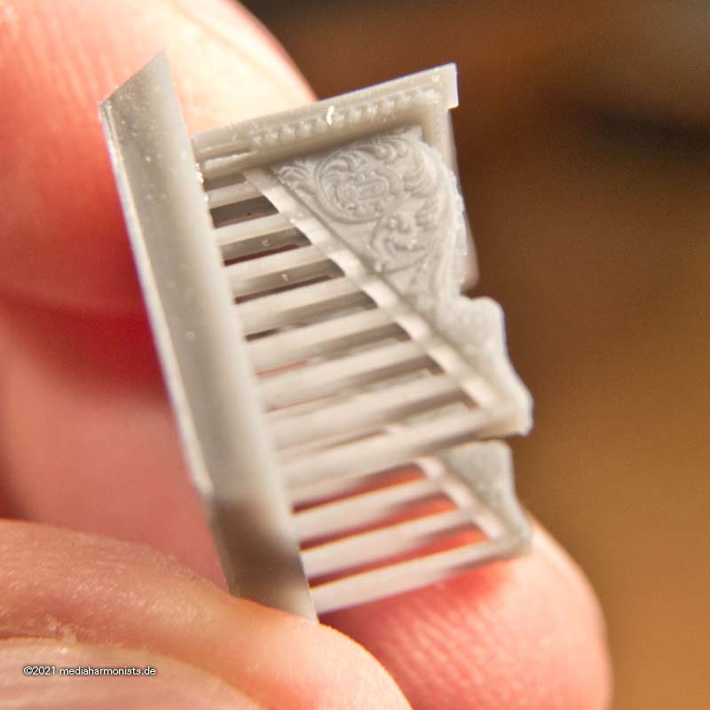
And what is even more important, even in this size well paintable, for this I tried different heights in some printer's rounds, but I think now it fits 🙂
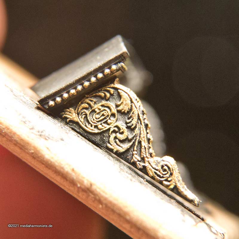
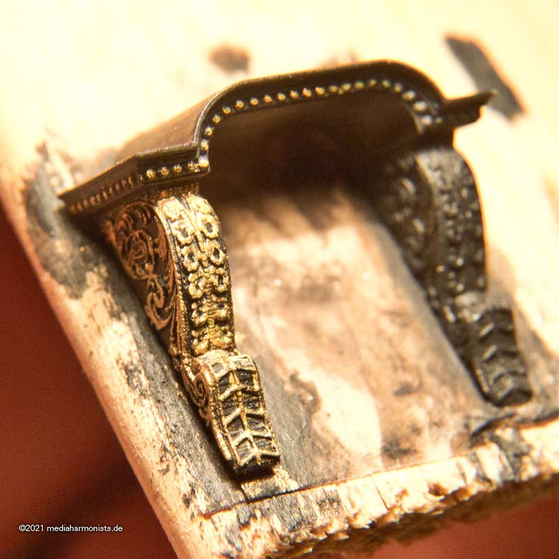
Enjoy!
XXXDAn
-
Another discussion led here in MSW is to be found here:
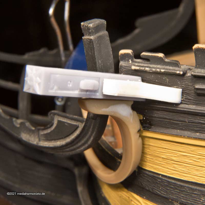
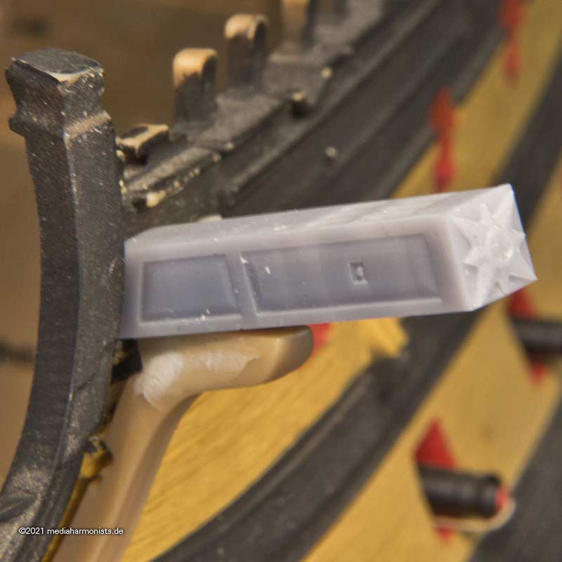
One of the given reasons for the mortise in the lid as for my understanding was to seal the lids. Here is a fast sketch:
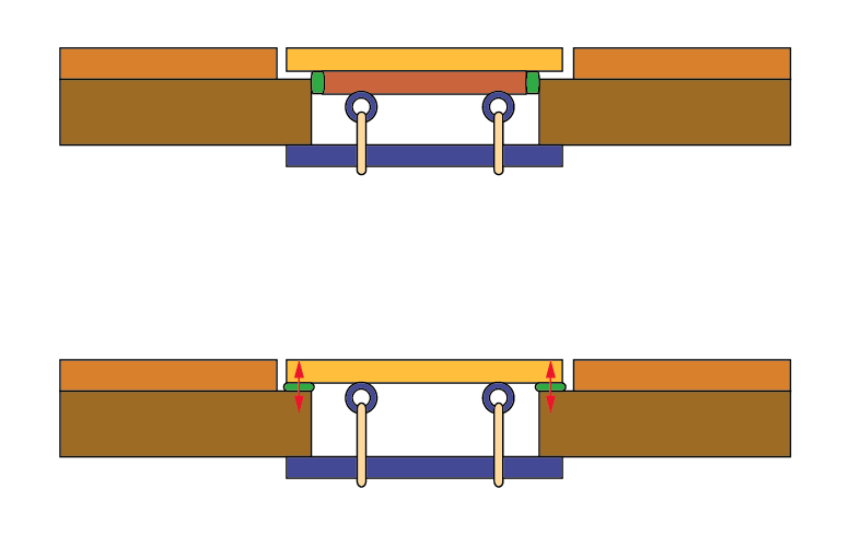
On the bottom you see how the lid is secured by the lanyards (or hooks) with the help of the blue batten against the hull. If one inserts sealing material like cloth or hamp one pushes the lid open, sse red arrows. On the top one sees that the sealing material is squeezed in between the gap and not giving too much pressure against the fastening.
XXXDAn
-
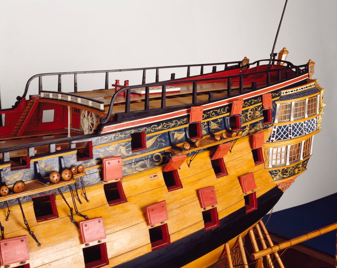
In our german forum we also had some heated discussions about the sense or need of the mortises in english ships. The famous model of the Prince of 1670 shows the mortises, but soon after this one disappears on most models.
On 9/22/2021 at 12:56 PM, allanyed said:I did find a French contemporary model, the Ville de Paris which has lids with the inner layer smaller than the outer layer, but so far I cannot find any British models with this construction. Photo of her ports is below. I checked another dozen or so contemporary models and the lids were all constructed with the inner and outer layers being the same outside dimensions.
Sometimes they are still shown so on the wonderful model of Bellona 1760.
SLR0338 https://www.rmg.co.uk/collections/objects/rmgc-object-66299
Still the discussion rages as some believe that the mortise needs to be there for good sealing of the ports. But still why are they then neglegted on most models? Were those "fashion items" that followed the taste or experience of the shipyard or master of construction?
XXXDAn
-
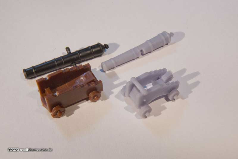
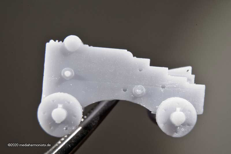
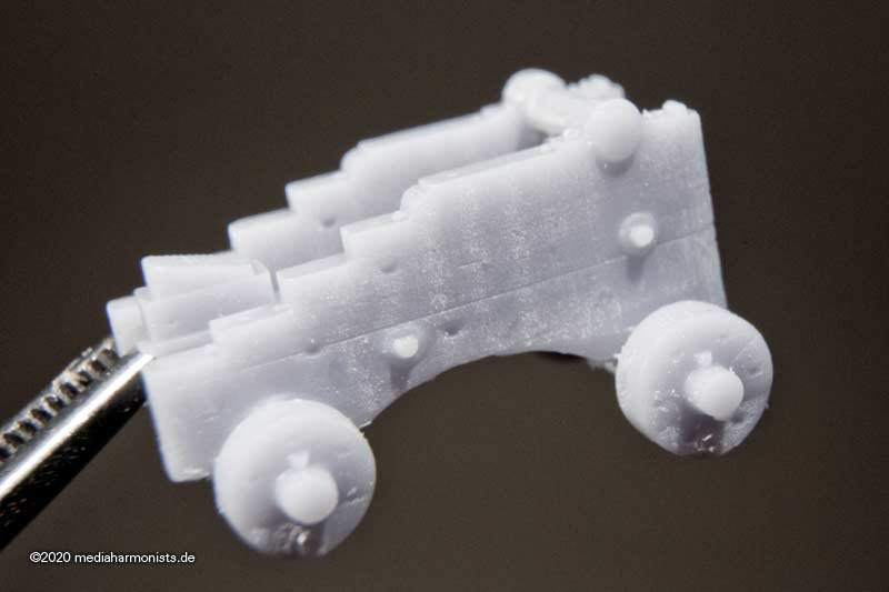
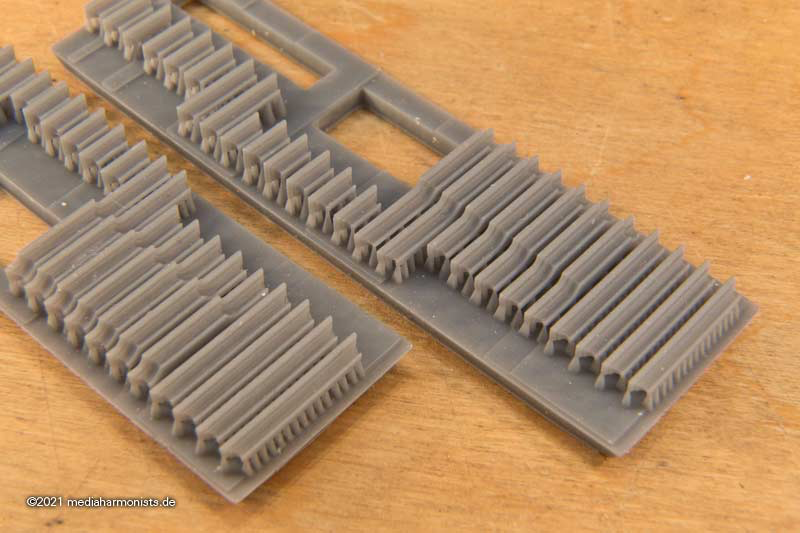
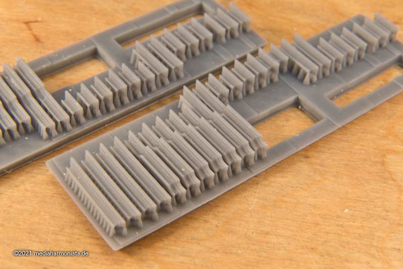
Yes it is a marvel what those new machines can do. Here is a test shot for my USS Costitution 1:96 from Revell.
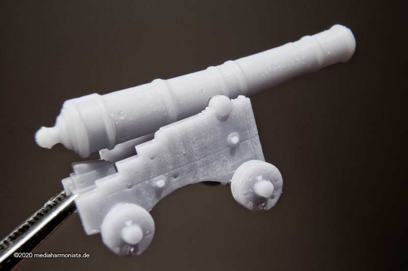
The big flaw of the kit are the guns, so I did some for my own build. Here in the picture on the left the Revell gun, and right my version following Marquardt´s plans. In the background one of Victory´s guns, showing that even kit´s guns can look good 🙂
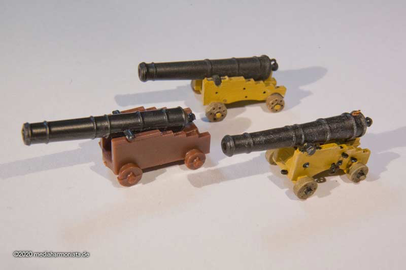
The amount of detail is amazing, here the flaps for the trunnions 🙂
Here more details of what is possible even at this scale.
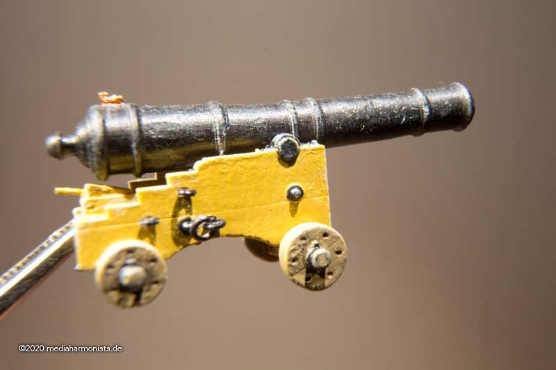
But what is also important is what we do out of these new parts, how to bring them to live. Still we are model makers!
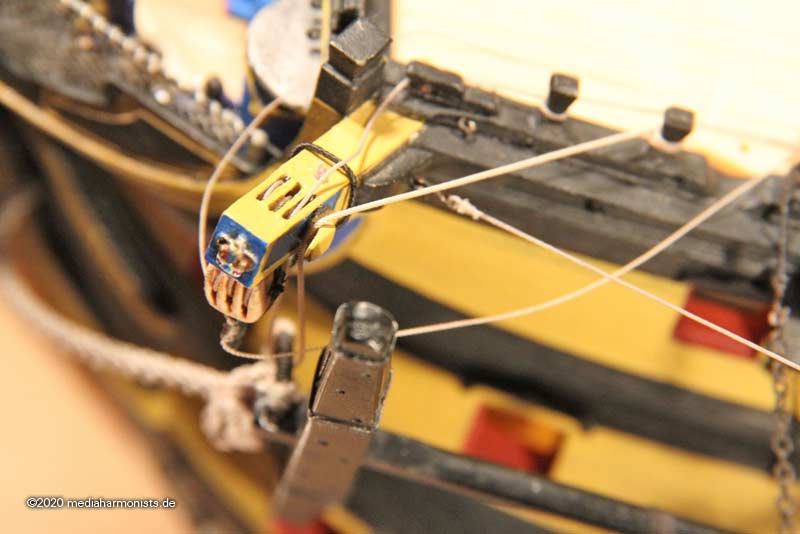
So with some paint, ink, brushed highlights, flintlock and real eyebolts the visual effect can become really strong.
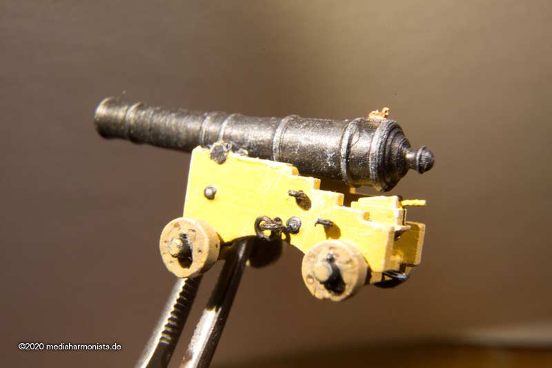
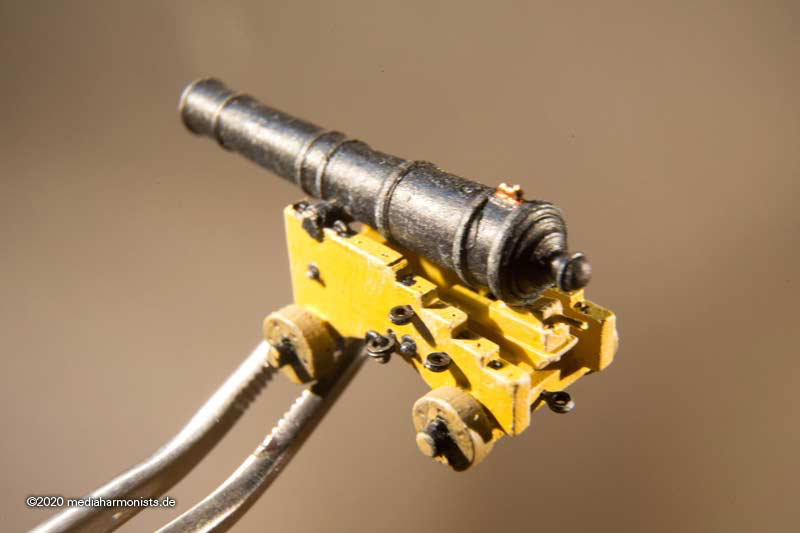
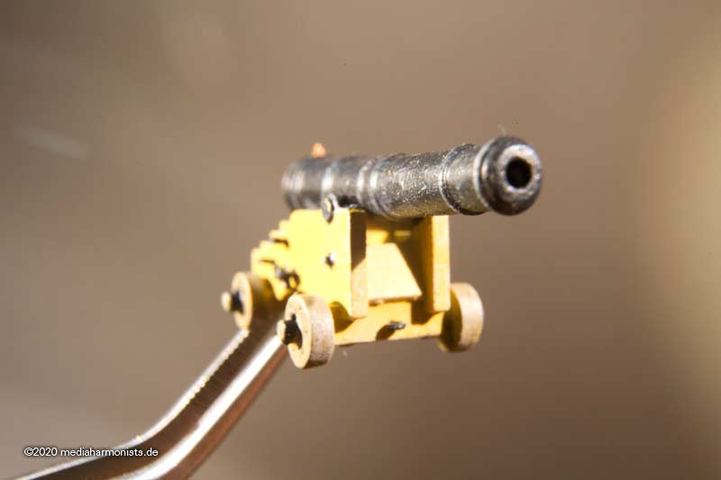
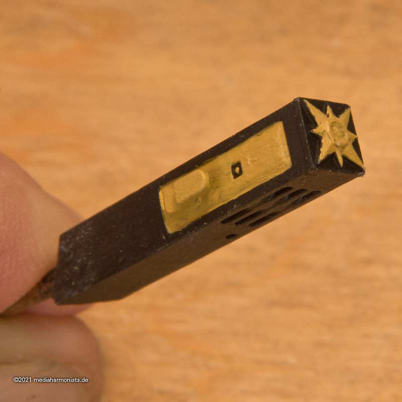
And not to forget the size, here some fingers in comparison 🙂
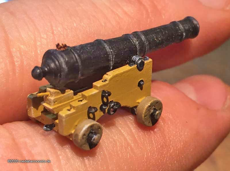
XXXDAn
-
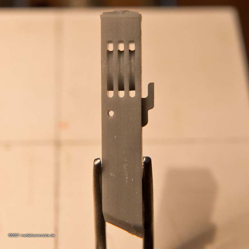
Just found by chance in the vaults, the mariners walk. I used the cutouts of the new holes to make up the old ones 🙂
XXXDAn
-
Most Honorable Order of the Garter? Honi soit qui mal y pense 🙂
https://modelshipworld.com/topic/30106-british-catheads-in-about-1800/
XXXDAn
-
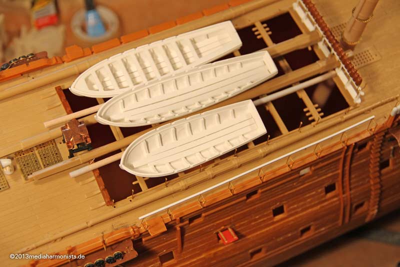
As already claimed, the spars were usually placed amidships. in the old days over the waist from fo´castle to quarterdeck, later on the gallows or simply on deck. Later when the waist was covered up, the spare spars stayed there in between the boats. Usually only roughly finished, as nobody knew before what was going to break and like this they could be more easily adopted.
The system was the same, here some trials on the Vic.
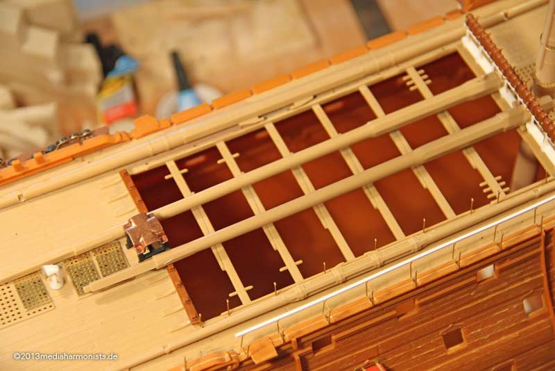
The log of the Victory indicates on 15-19.04.1778: Spare topmasts and spars shipped in
Also NMM shows severals plans where the spare spars are shown.
HMS Vanguard 1835 http://collections.rmg.co.uk/collections/objects/80305.html

And the closest for the project mentioned first is the UNITED STATES with the plans for spars and boats.

See the stunsail booms on the fore channels, 3 more boats were hung on the wdavits.
XXXDAn
-
Look here in some pictures you can see the mariners walk and count where the 3 holes have to be.
For the missing crown: As my research in my own building report shows that there should not be a crown but the Most Honorable Order of Garter, if you would like have 2 of those I could just send it to you 🙂
All the best, Daniel
-
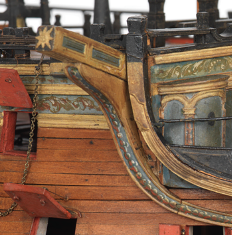
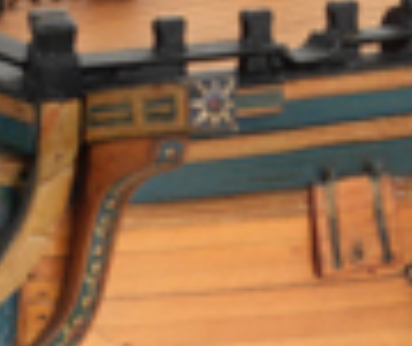
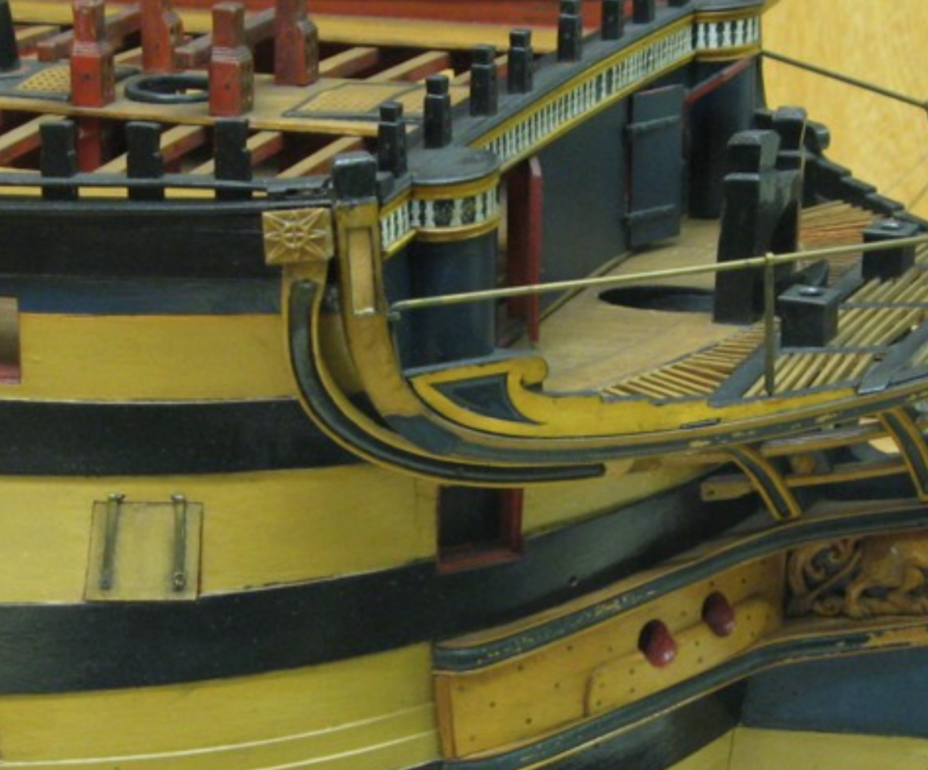
Thank you for all the feedback. I was made aware that the Most Honourable Order of Garter not only was used for the cathead, but also for other decoration, her the stern of a small frigate.
36 Gun Frigate
Scale 1:48. A contemporary full hull model of a 36-gun fifth-rate frigate (circa 1801). SLR0643 XXXDAn
- BANYAN, Beef Wellington, druxey and 1 other
-
4
-
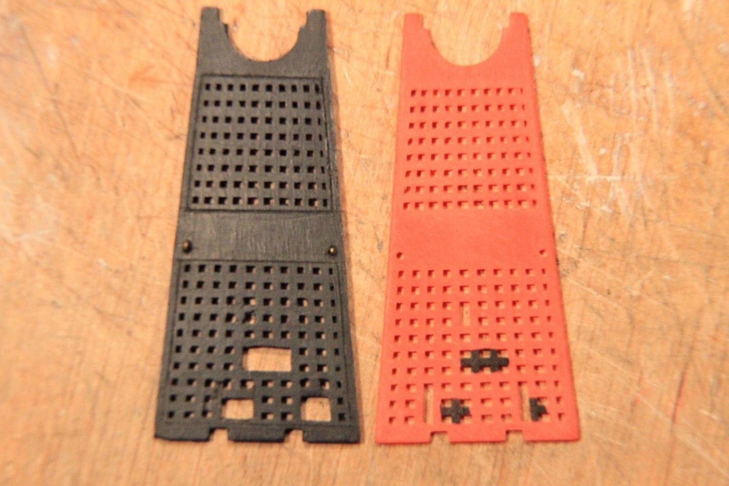
As the better is always the enemy of the good, here comes the next step, or better saying come the next steps.
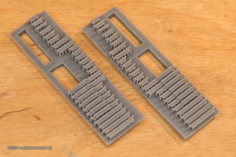
Stairway to heaven 🙂
XXXDAn
-
Thank you @druxey,
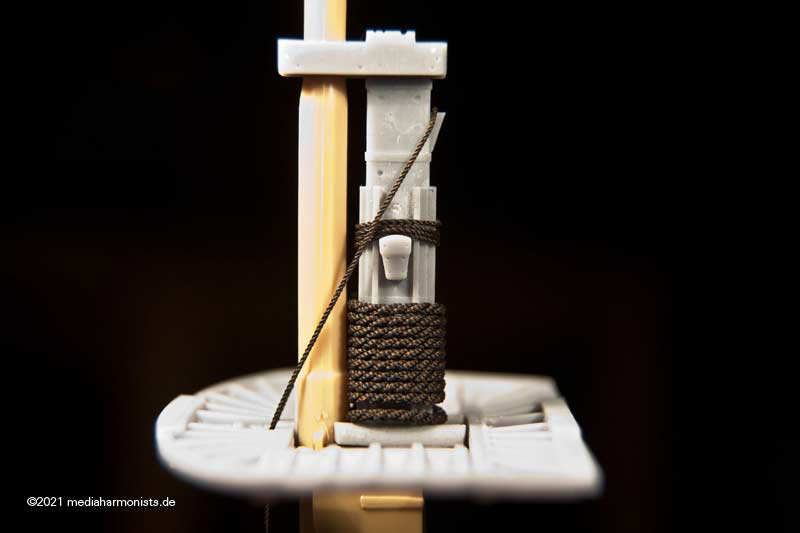
this one is for the hanger. But you are correct in times of war most systems were redundant. This would then be like the last picture in my last post showing the chains and the rope over the top. It makes sense to attach the chain on the cleat in the back, as there are the sharper angles, no problem for the chain. The rope instead would profit from the radiuses of the bolster.
Would the chain be smartened in the ared of cleat, edge of the masttop and the jeers cleat? Would make sense but never really jumped to my attention.
Also still have to fiddle out how all that fitted to the yard ...
🙂
XXXDAn
-
Thank you Jason,
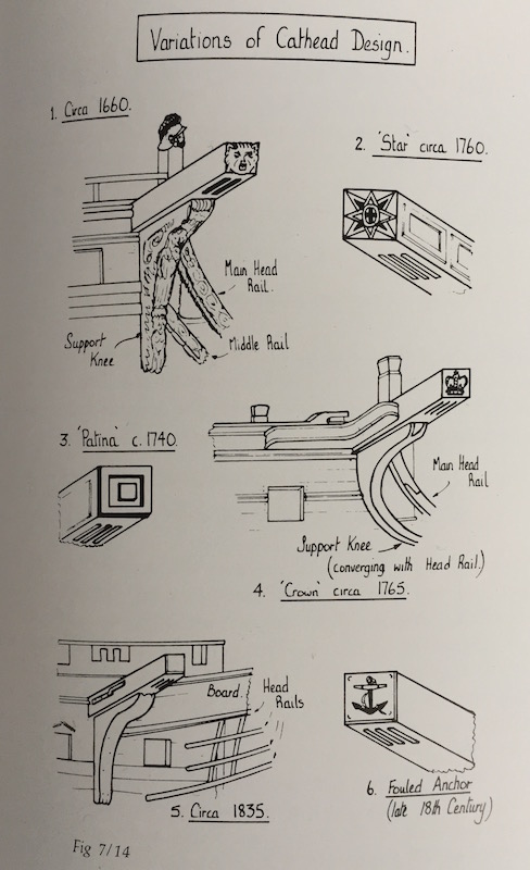
it was a while that I was made aware, that the crown seen today on Victory´s cathead is not an usual symbol to be placed there. At the times when the Victory was build, there was a "star" (even Goodwin puts it in brackets) that I believed to be a compass rose. But still the design did not fit with the classical compass rose, which by the way was used often for the flooring in the captains´ cabins and which looks like we know it. It is the vertical cross in the middle with the circle around that irritated me. Alternatively fouled anchors (f. e. HMS Queen Charlotte) or simple cassettes could be displayed there.
The one contemporary model of the Vic shows this "star"
The other contemporary (?) model shows the color inlays
This is what L. G. Carr Laughton reports in "Old Ships Figure-Heads and Sterns"
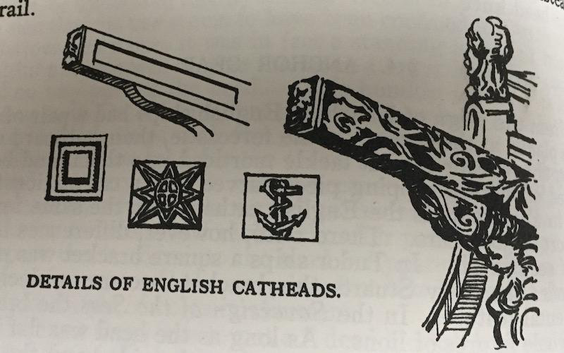
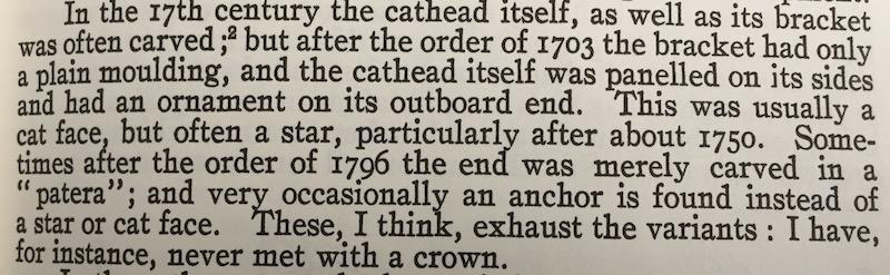
Goodwin shows the crown (wrongly for 1765 - earliest 1803) but also quite clearly shows the "star" as no compass rose
Here @achilles well researched model of Queen Charlotte, following the contemporary model.
Quite clearly HMS Boyne 1790
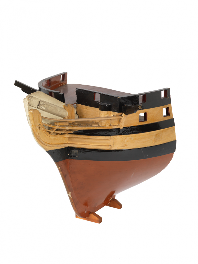
Also this Sectional model; Bow model SLR2185
And the final clue was the NMM itself, but only after I was pointed by a german forum´s comrade towards this possibility:
HMS Vanguard (1835); Warship; Third rate; 78 guns, 1835
The catheads are depicted, their ends being painted with garter styles.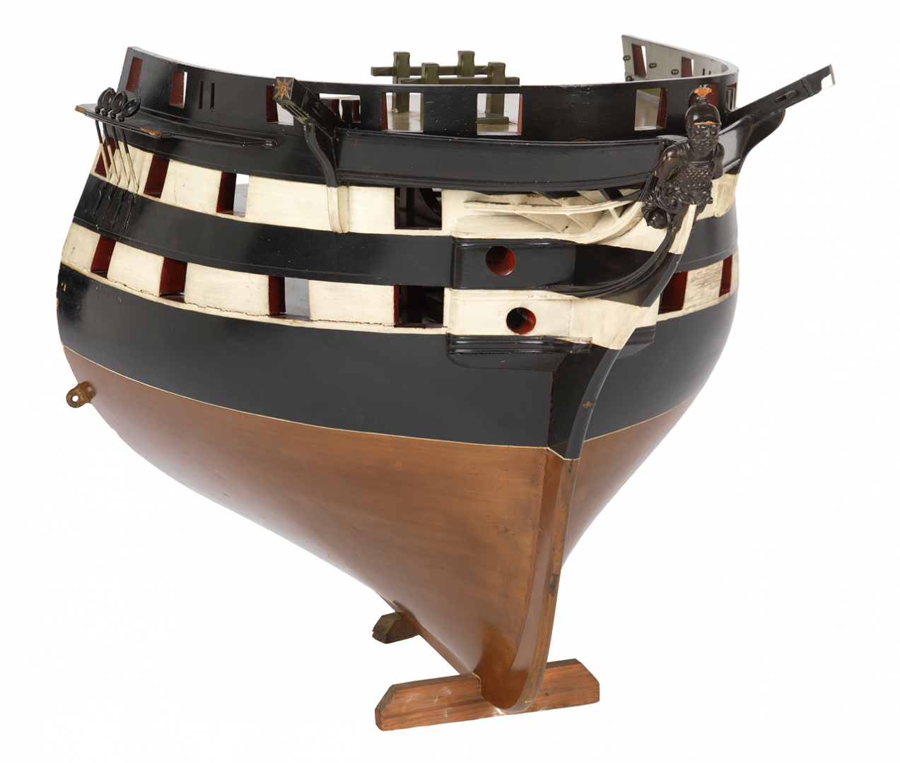
Warship; Frigate Scale: 1:48. SLR2197
"... Fittings include a pair of catheads with garter star end decoration; ..."

And here it is again as comparison, the Order of Garter.
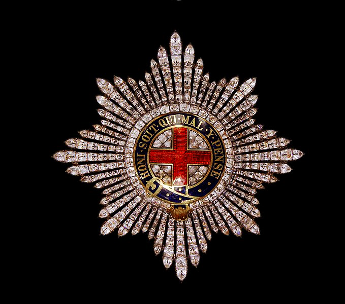
And it makes completely sense, as the Order of Garter was also incorporated in the Royal Coat of Arms and therefor in the figure head of the Victory 1803.
Honi soit qui mal y pense 😉
XXXDAn
-
Thank you druxey, I am quite with you there, but still ...
And I've gone through the different possibilities that come into question for the hangers. The ropes are just place holders. The jeer cleat could be placed a tiny bit down what would ease the case, but still ...
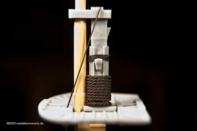
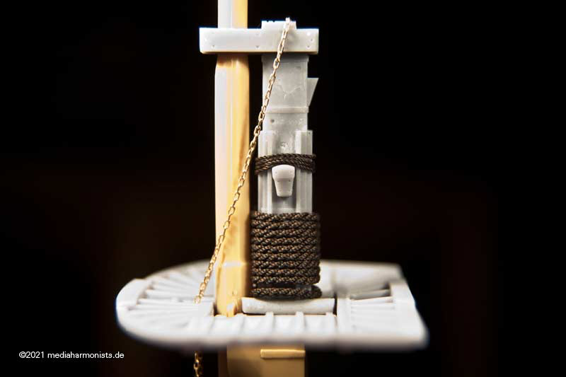
One sees, that the bolster on the cap is the most elegant solution. I don't know to what extent the hanger running over the jeer block lashing tends to chafe here, since both parts are static. Above all, the fact that the stopper cleat at the rear is the only version mentioned in contemporary sources gives me reasons for further investigations.
Only the bow-shaped jeerncleat I would have reservations about the hanger running over it; here the two actually interfere with each other.
I'll keep digging.
XXXDAn
-
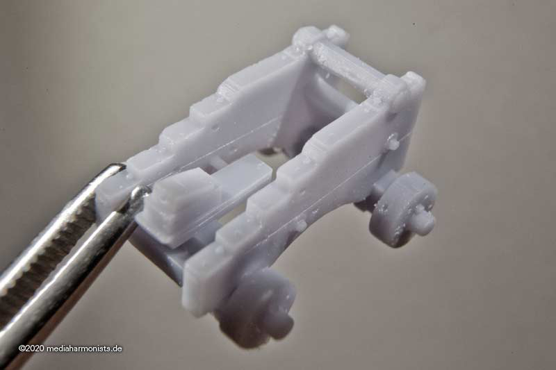
Did not have the chance to real tinker in 3D so I tinkered at least a bit digital in 3 D 😉
Gives the chance to overwork the parts, try out things and so to clarify the last issues and uncertenties that I have in some points. After the cleat for the fore and main yard jeers*** comes the other one 🙂
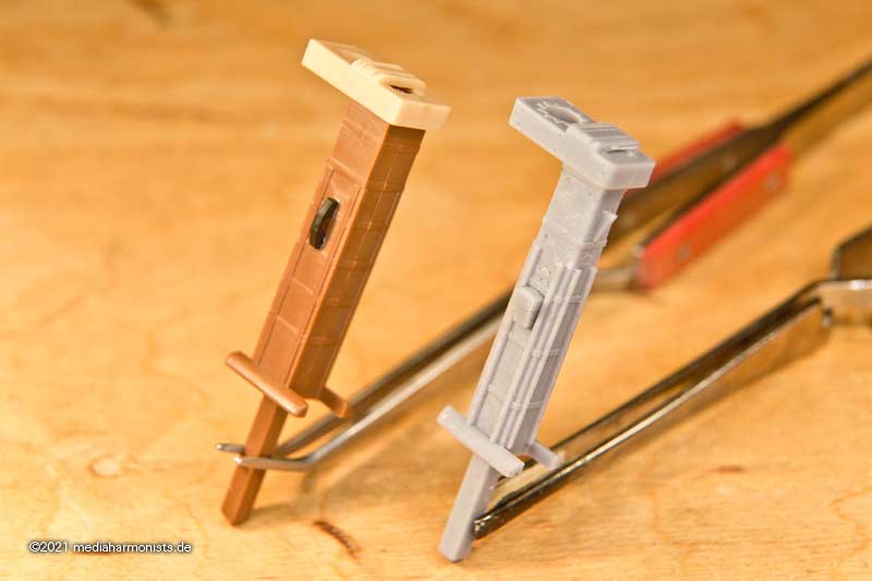
But first, also here the difference between the kit on the left and the classically tinkered fore mast on the right, which can be recognised by the missing rake of the bolsters 🙂
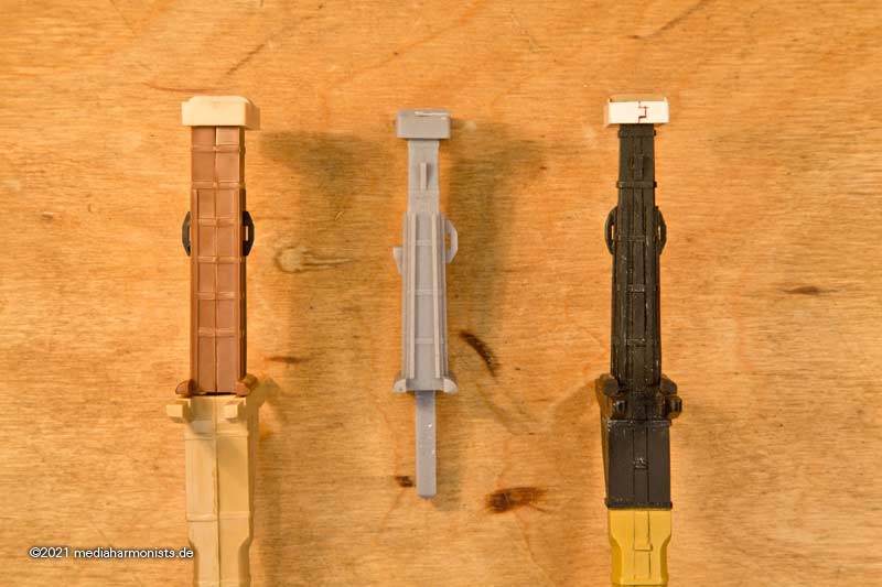
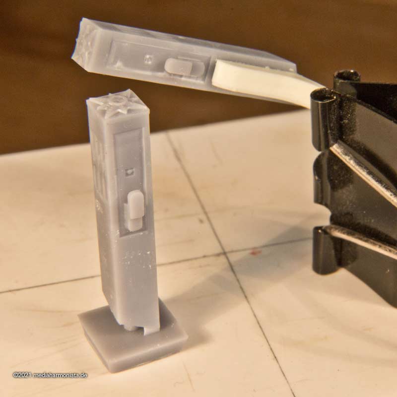
Redefined the mastcap, showing the splitlines and now also including the small and seldom seen detail, the triangles of the leather lining in the hole for the topmast.
My uncertinty is upon the two bolsters of the cap:
The front one with two thin grooves is for the lifts, the thicker aft one is for the yard slings. Were they in use in about 1800?
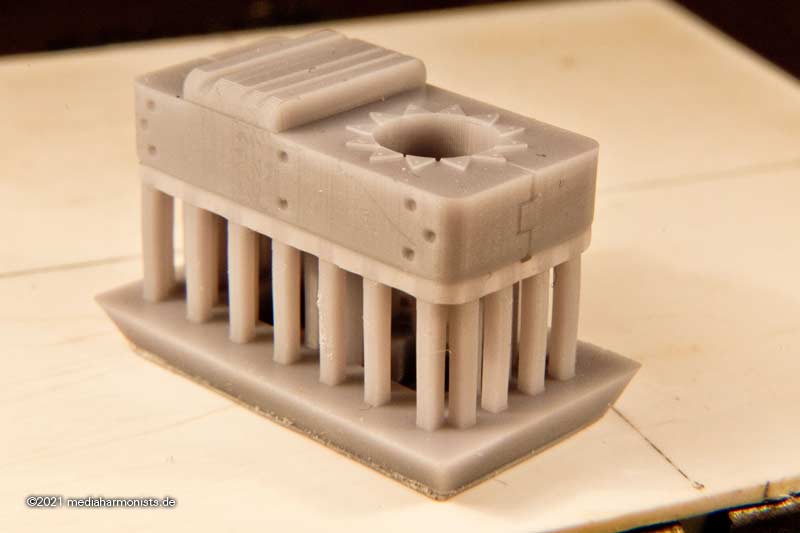
The two thin grooves are meant for the yard lifts, a version seen in Portsmouth and Klaus Schrage and K. H. Marquardt.
Here the blocks are not hanging on eyebolts underneath the cap, but are led on a doubled rope over this bolster, as shown by Schrage.
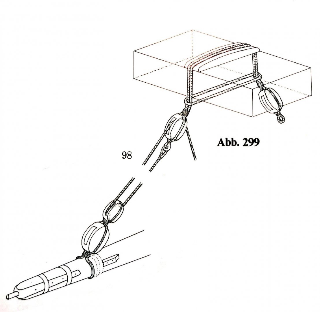
Here is the question, if there are any information about the attachement of those lift blocks in 1800. Was the front bolster used for the blocks of the lift or were they fixed with an eyeblot from underneath the cap?
Next question is about the aft bolster with the thicker groove for the lead of the yard sling (blue arrow). Again this use is found in Portsmouth. Here also I found two versions, as most other sources, contemporary and also modern ones indicate a stopper clamp on the aft side of the mast head (green arrow).
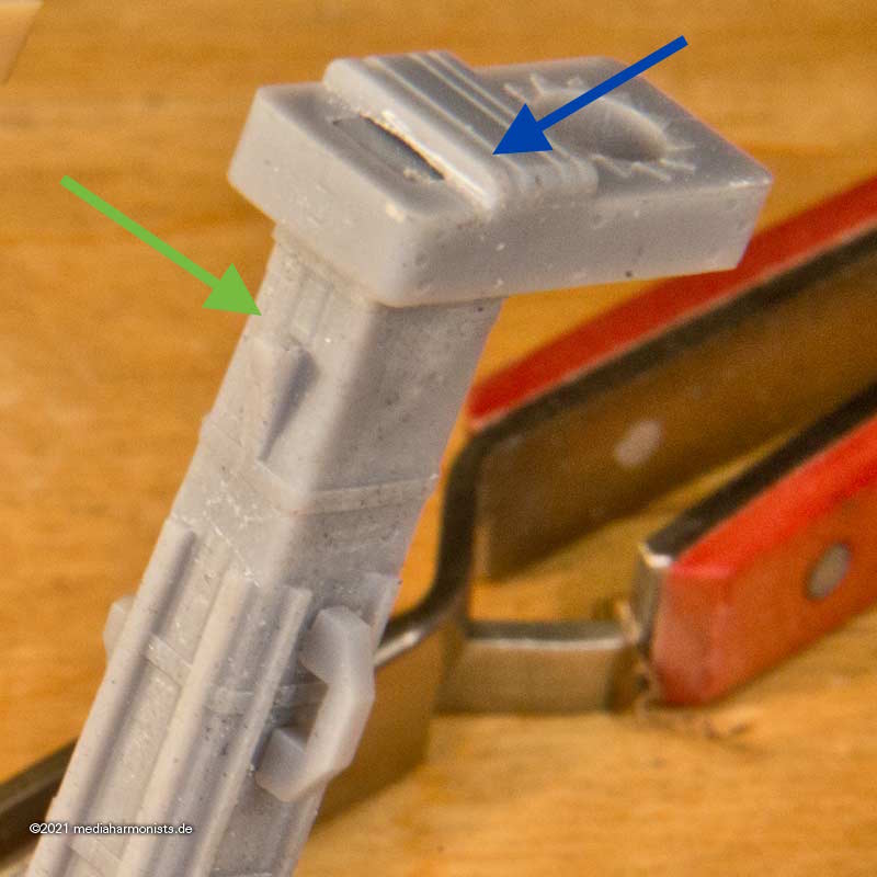
The aft bolster is according to Portsmouth and Pettersen. The aft cleat according to most other sources.
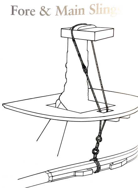
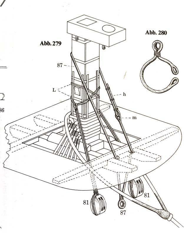
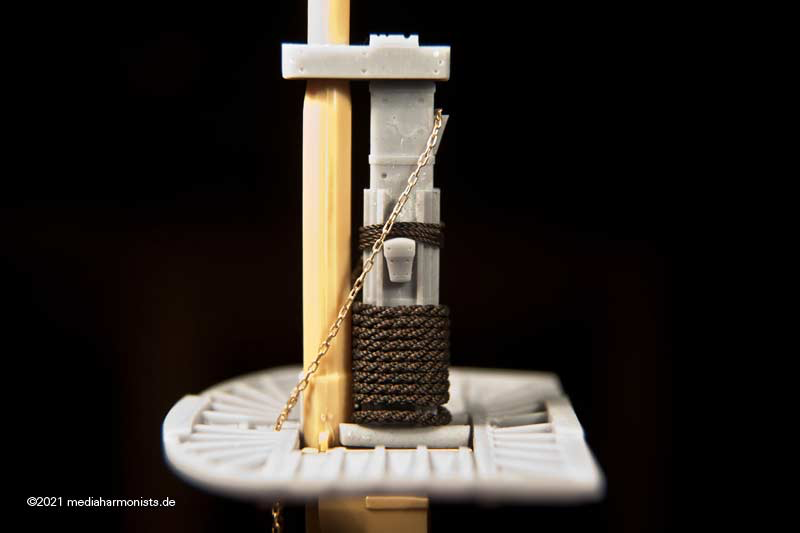
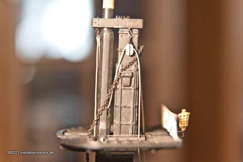
Another point that I was realising. Lees claims, that "... these rope slings were changed to chain slings during wartime ...". As 1803 to 1805 the war against France was raging fiercely i was opting for those chain slings for my Vic. A test fit revealed that the version with the bolster keeps nicely clear the jeer block lashing. - do not mind the top tackle in the picture 😉
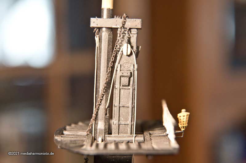
On the other side the cleat in the back is a quite tight fit. Here in my opinion the stopper cleat in the back is to low and the cleat for the jeer block lashing too high, so that they collide.
Again any information about this issue available? Is the bolster obsolete or a good version? Also, if the cjain slings are used, was there still a preeventert rope sling?
As always, greetings from a wondering dafi ...
XXXDAn
***
-
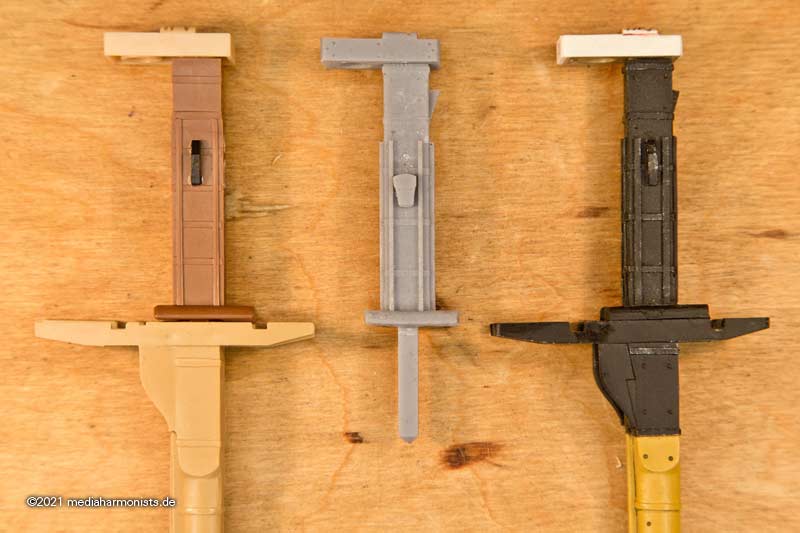
Did not have the chance to real tinker in 3D so I tinkered at least a bit digital in 3 D 😉
Gives the chance to overwork the parts, try out things and so to clarify the last issues and uncertenties that I have in some points.
But first, the difference between the kit on the left and the classically tinkered fore mast on the right, which can be recognised by the missing rake of the bolsters 🙂
The kit provides two bow-shaped cleats at the masthead to suspend the jeer blocks, as also last seen on the Vic (when she was still masted). Portsmouth, McKay and Peterssen show that sort of cleat. Actually I found no contemporary source showing this form ...
On the other side all the contemporary sources I found, among them David Steel, but also modern sources like James Lees, K. H. Marquardt and Klaus Schrage, see a shoulder-shaped jeer block cleat at this purpose.Here the two versions in comparisson. For the tackles itself it does not make any difference. Both sitting on the same place. The clamp shaped one is probably more difficult to set op as the rope has to be led through, but gives some protection against falling off while doing this. Once set I believe both versions to give the same support.
Since I assume that both variants were once in use, here the question:.
In which time frame or on which class of ship these variants were to be applied? I haven't found anything on this yet.
I also found the shoulder variant much pre 1800 and also much later, so I believe this to be the more plausible variant.
Is there any info about the clamp shaped cleat available?
All the best, DAniel
-
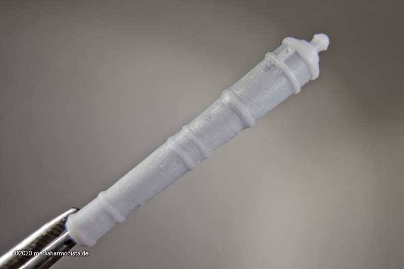
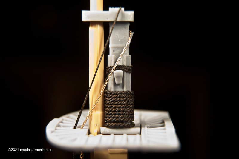
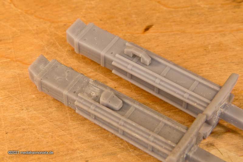
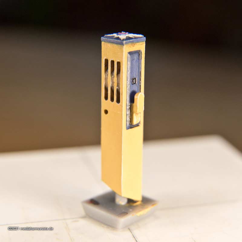
After having finished some touch-ups, the slots of the rollers at the end are round - usually the inner edges were drilled first - and also the hole for the stopper knot of the cat tackle (or fot the cathead stopper?) is there now. Also the cleat now sits in such a way that the bolts to it should not get in the way with anything else.
And this leads me to the next question.
I had always assigned the hole in the beam to the cat tackle. It makes sense to take it directly behind the slot for the fixed end. However, Marquardt assigns it [i]also[/i] to the cathead stopper and leaves the attachment of the cat tackle unclear.
In my model, I had previously assigned the cat tackle to the hole and placed the cathead stopper around the beam secured by an eye. Who knows more about this?
XXXDAn
-
Thank you guys 🙂
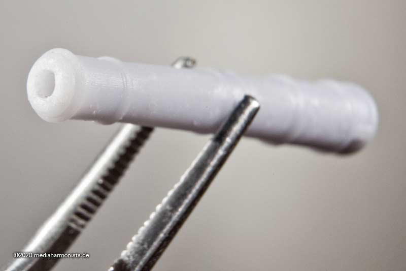
As I said, I needed some touch-ups, so I rounded the slots of the rollers at the end - usually the edges were drilled - and also the hole for the stopper knot of the cat tackle (or for the cathead stopper??) is there now. Also the cleat now sits in such a way that its bolts to should not get in the way with anything else 🙂
Checking the angles, fits so far 😉
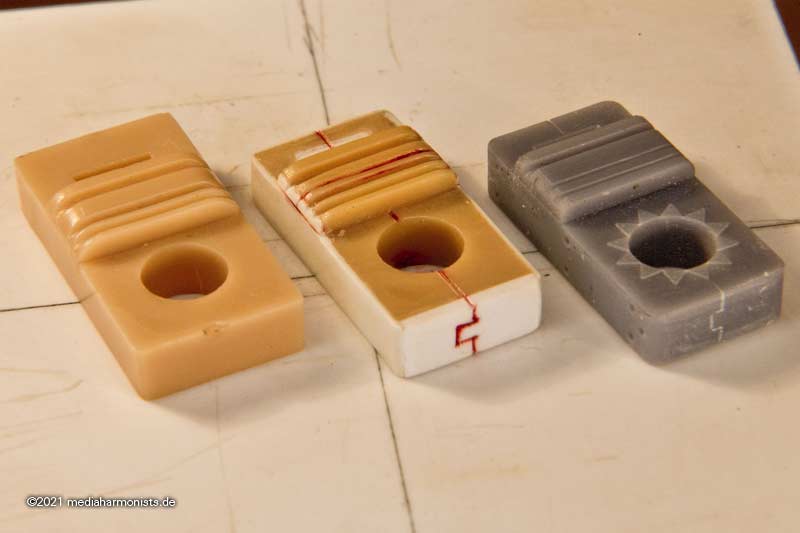
And then first the colour samples. Here is the pure colour.
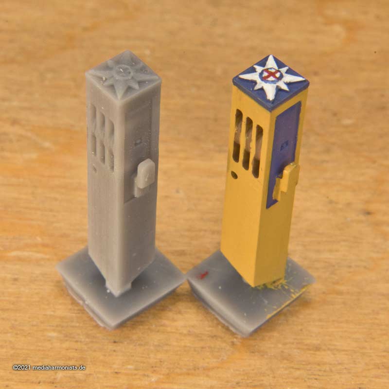
And then my usual treatment with black ink in the inner edges and white brushing of the outer edges. It looks quite different again 🙂
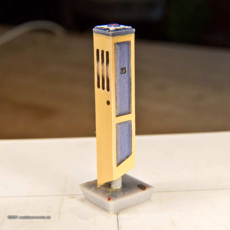
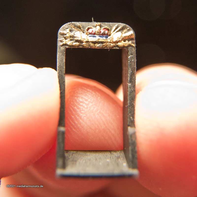
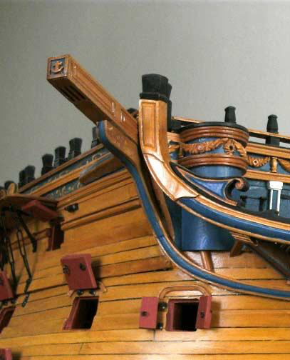
And here is the Order of the Garter in its original colours.
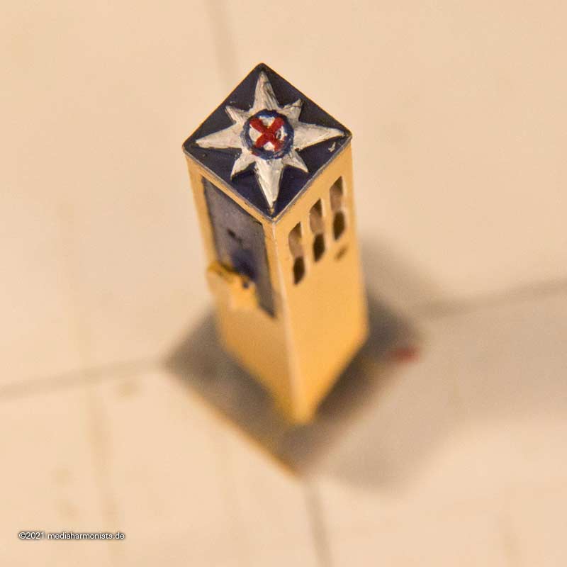
Whether it was so colourful around 1803 is questionable, since all decoration was cut back. Therefore, inspired by contemporary models, here is another version.
XXXDAn


Manning the capstan
in Discussion for a Ship's Deck Furniture, Guns, boats and other Fittings
Posted · Edited by dafi
This can be seen on other jobs too. As long as the marines were not needed on deck during battle, they were manned as auxiliaries at the guns. So here one red frock on each side to help pulling the tackles 🙂
XXXDAn