


dafi
-
Posts
2,297 -
Joined
-
Last visited
Content Type
Profiles
Forums
Gallery
Events
Posts posted by dafi
-
-
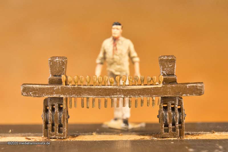
I'm having a bit of a headache with my bits on the Victory.
According to McKay and the Heller kit, the pins are set very tightly there.
The forward foremast bit is still manageable, according to AOTS the cross bar has 5 ropes, so some space is left in between for the coils.
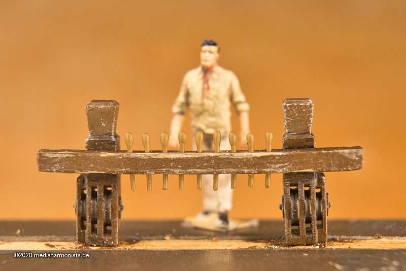
For the aft foremast bit of the same length, there are 17 pins for 16 ropes. It then looks like this:
This is McKay´s belaying sceme from one side to the other (with reference number of the AOTS):
108 Fore Yard Slab line
211 Main Top Gallant Bowline
125 Fore Top Yard reef Tackle Pendant
free
148+140 Fore Top Gallant Tye + Fore Top Gallant Halyard
92 Jib Halyard
170 Main Yard Bowline
168 Main Yard Buntline
94 Fore Yard Truss Pendants
168 Main Yard Buntline
170 Main Yard Bowline
91 Jib Stay
free
131 Staysail Stay
125 Fore Top Yard reef Tackle Pendant
211 Main Top Gallant Bowline
108 Slab line Fore YardCan this be true?
- Aren´t there too many pins on the cross bar?- Too many ropes that could go somewhere else? Is the bit too narrow?
- Should there be less pins and some ropes being attached to same pins?
What does Steel say about the dimensions of the bits? Any other advice on bit dimensions and number of belaying points?
And therefor: What is the tightest spacing of of the belaying points/pins?
Questions about questions ...XXXDAn
- mtaylor and Keith Black
-
 2
2
-
Sometimes I am stupid ...
I had already described the initial situation a long time ago. The bits of the kit were "a bit" strange in their shape. Thereupon I had fiddled new ones ...
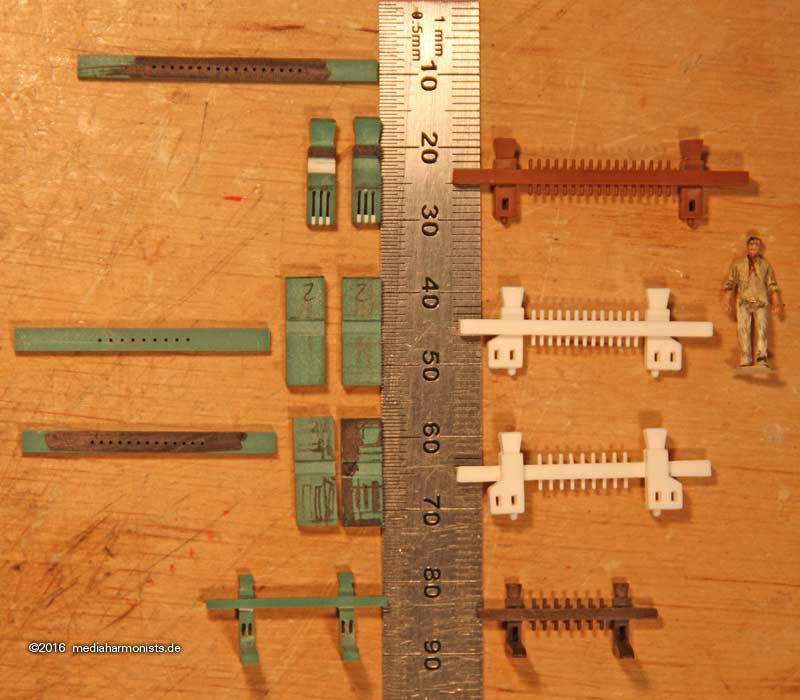
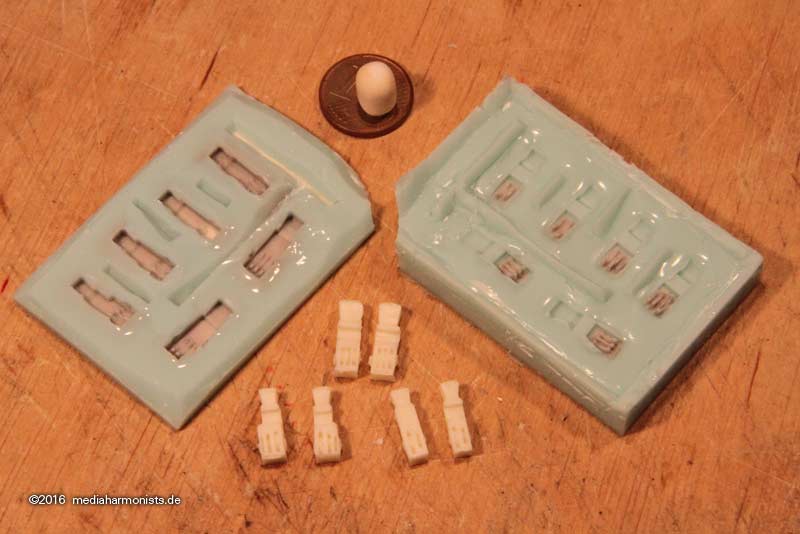
... and because I need some of them for different tasks, I casted them. A complicated mold with two-component silicone putty inlets - top tec
 [/img]
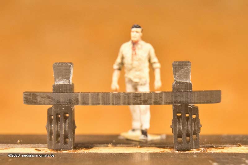
The other day, I noticed that the bits are still pretty low, even though I had my scale mate with me when I took the photos ...
... grrrrr...
Here again the summary:
Kit
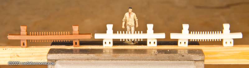
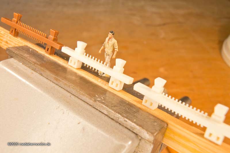
Version 1 anno 2016:
So consulted the McKay and printed the parts in these dimensions.
And since I want to be a model builder, i tinkered around with the printed parts, and got this 🙂
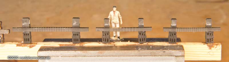
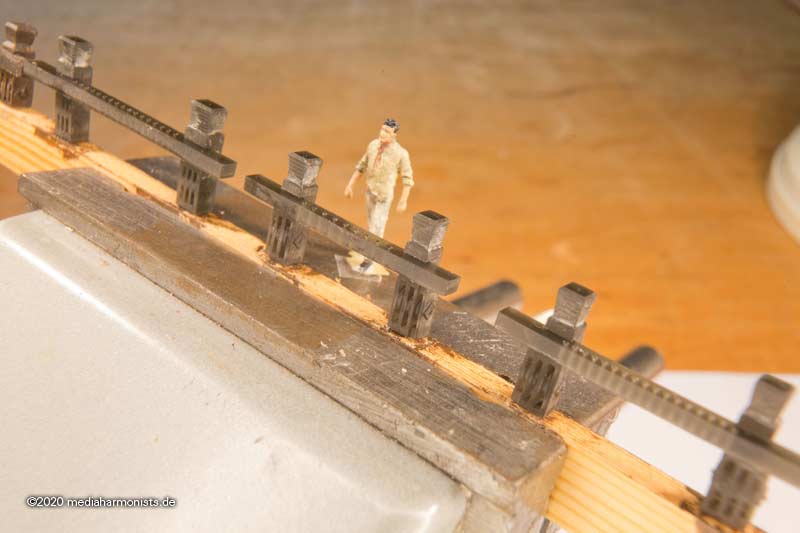
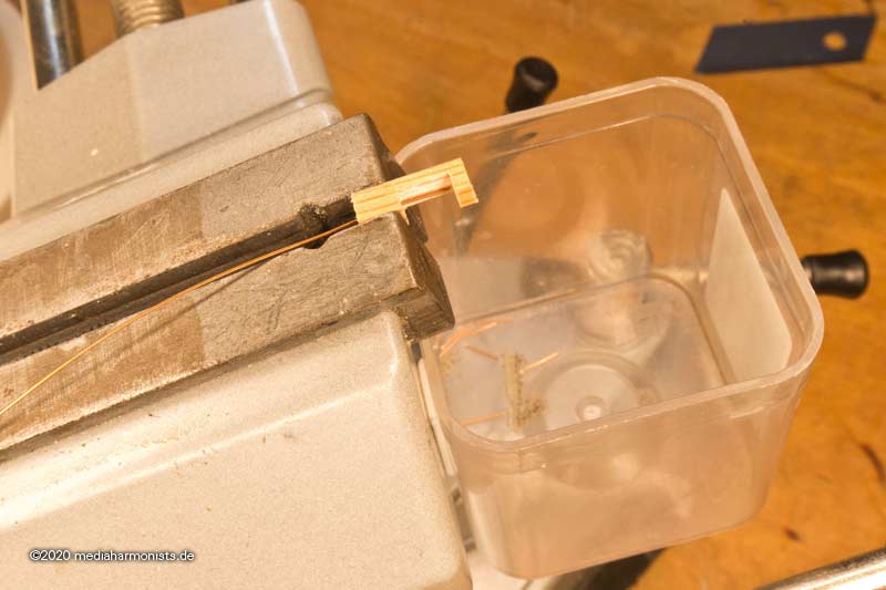
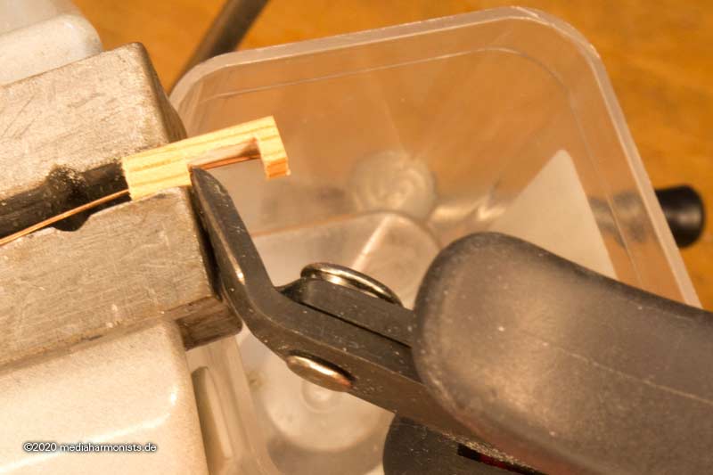
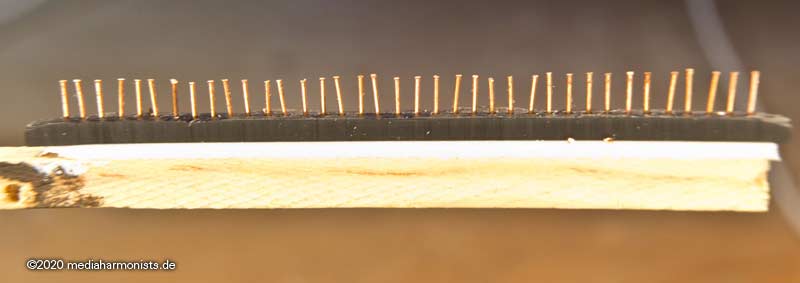
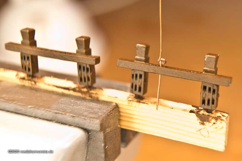
For the belaying pins I made a template to cut to length, with wire feed from the left, and catch basket underneath, goes smooth and
quickly and well cut to 6 mm.
Then a montage holder with through holes - needed print wise - taped with mirror tape to a wooden stick and filled with the cut offs.
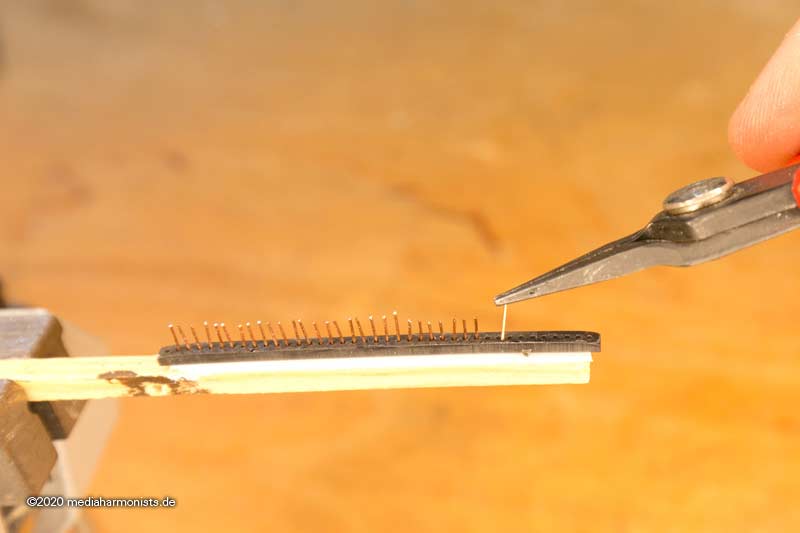
The mirror tape actually secures the wire pieces against falling out. After that I leveled the lengths a bit ...
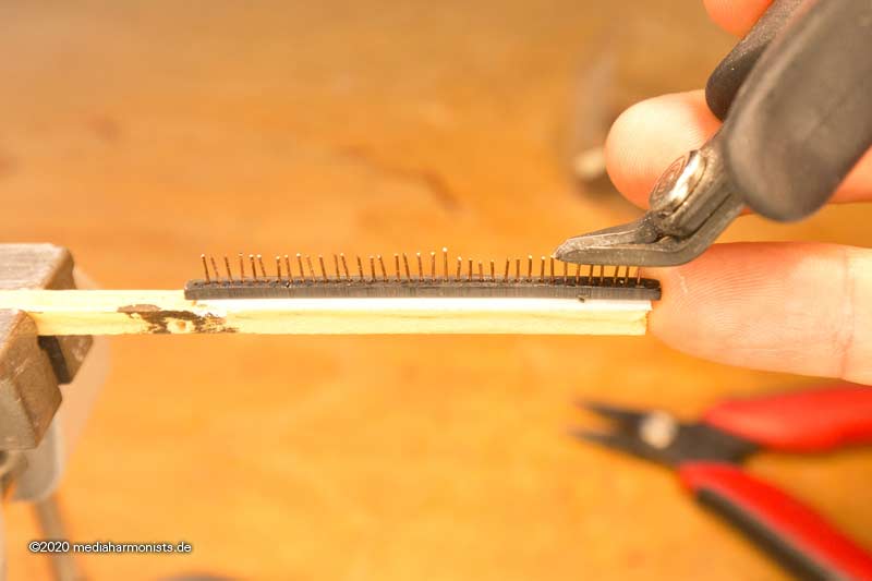
... it looks like this:
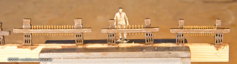
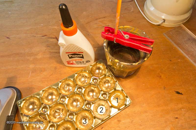
Then prepared the pin head. White glue in cup 1, water in cup 2 and the mixture in cup 3. And for that the brush does not dry out when the pin is left to dry, it is brought to the right height with a clothes peg so that its tip is in the water.
Then the glue is applied in several layers on both sides of the head. The thinner the glue, and the more layers there are, the more uniform the result. So do not make the first layers with a too thick glue-water mixture! And always let it dry befor the next touch up. That's why I use the white glue "express" version, so that work can proceed quickly.
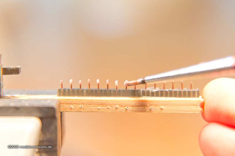
In my case it was 6 to 8 layers. When the head has the right size and form, let it dry well and paint it 🙂
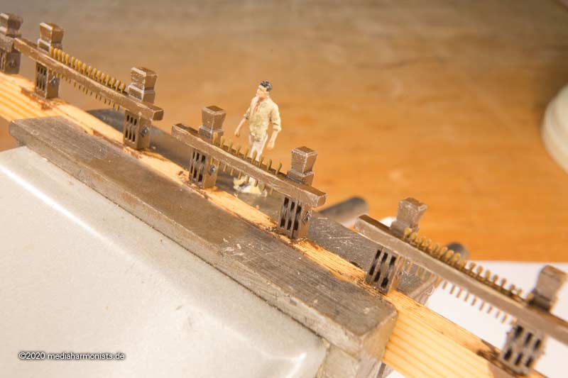
Then paint the bit itself with the base color ...
... and keep the holes open.
After that I like to put thinned ink in all the inside edges, it adds depth. Next a light wood color on all scuffed edges and finally some white brushing on all outside edges, it just always gives a good look.
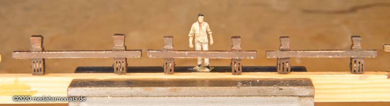
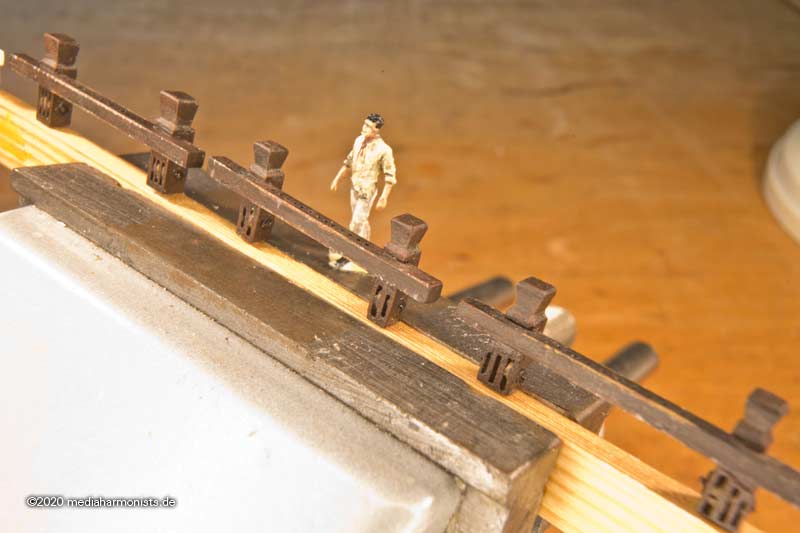
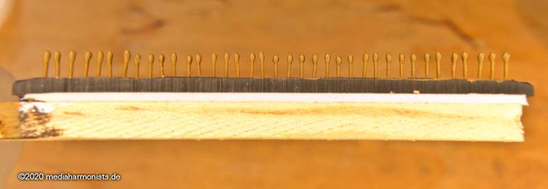
Then inserted the pins, secured with white glue - which dries transparent - level the top side, bring it to a leveled length on the underneath side where necessary to adjusted the lengths and added the color.
And what used to look like this ...
... then becomes like this. So even printed parts need a lot of love and affection from a tender modeler's hand 😉
XXXDAn
-
I would be very cautious with McKay as these are no contemporary evidence. Also he draws the deck patterns with all planks in approx 6 meters long without respecting the beams underneath.
There are some nice contemporary plans like the ones mentioned above or also published by Steel.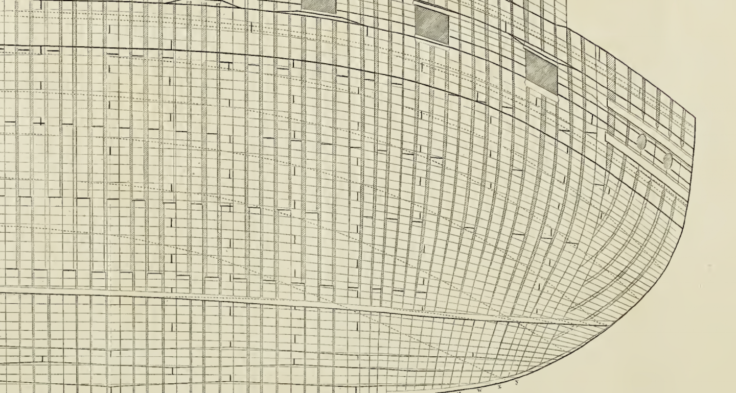
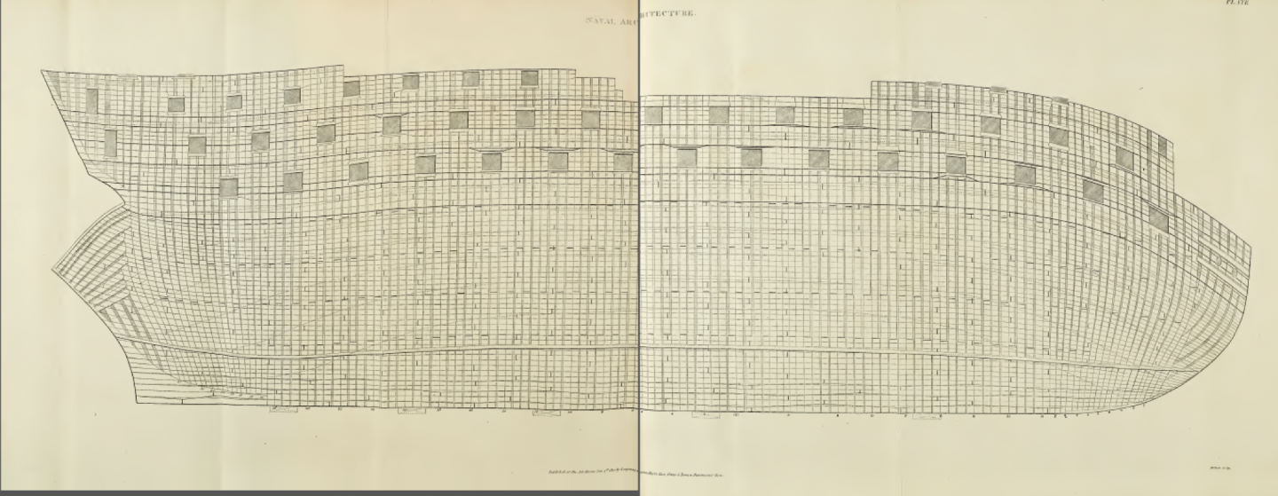
But I always am tempted to see those as idealized schematic proposals. In the yard they imho had to be sparing with the material, especially in war times. So I believe they never would have cut a plank short just to fit the pattern, especially as the strongest version of building was using as long planks as possible. 🙂
And anyway, I am following since long all excavations available - none of them shows 1:1 all the theory of Steel and others ...
XXXDAn
-
One of the few boats that survived is the one of the Vasa. If I remember well it predates the ship of 1628 by far.
One sees a light convexity towards the end, also the inside has a clear direction, also the position otf the mast. Near the stern there are two small posts for the rudder.
[img]https://www.mediaharmonists.de/bilder/Stockholm/Stockholm-180323_8913.jpg[/img]
[img]https://www.mediaharmonists.de/bilder/Stockholm/Stockholm-180325_9570.jpg[/img]
[img]https://www.mediaharmonists.de/bilder/Stockholm/Stockholm-180325_9614.jpg[/img]
[img]https://www.mediaharmonists.de/bilder/Stockholm/Stockholm-180325_9615.jpg[/img]
[img]https://www.mediaharmonists.de/bilder/Stockholm/Stockholm-180325_9616.jpg[/img]
[img]https://www.mediaharmonists.de/bilder/Stockholm/Stockholm-180325_9617.jpg[/img]
[img]https://www.mediaharmonists.de/bilder/Stockholm/Stockholm-180325_9618.jpg[/img]
XXXDAn
- Cirdan, mtaylor and Keith Black
-
3
-
-
Just to continue the topic. Achilles from our german forum did build a magnificent Queen Charlotte 1790 in 1:48.
Included was of course the double decked pump that could be seen in the drafts shown in the NMM.
First the lower deck with the casing on the forward pump going to the middle deck. The aft pump is a classical "one deck" pump.
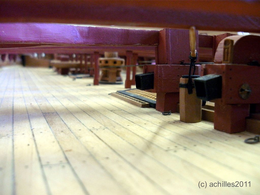
ZAZ0159
And here is the upper part of the forward pump protruding in the middle deck.

ZAZ0160
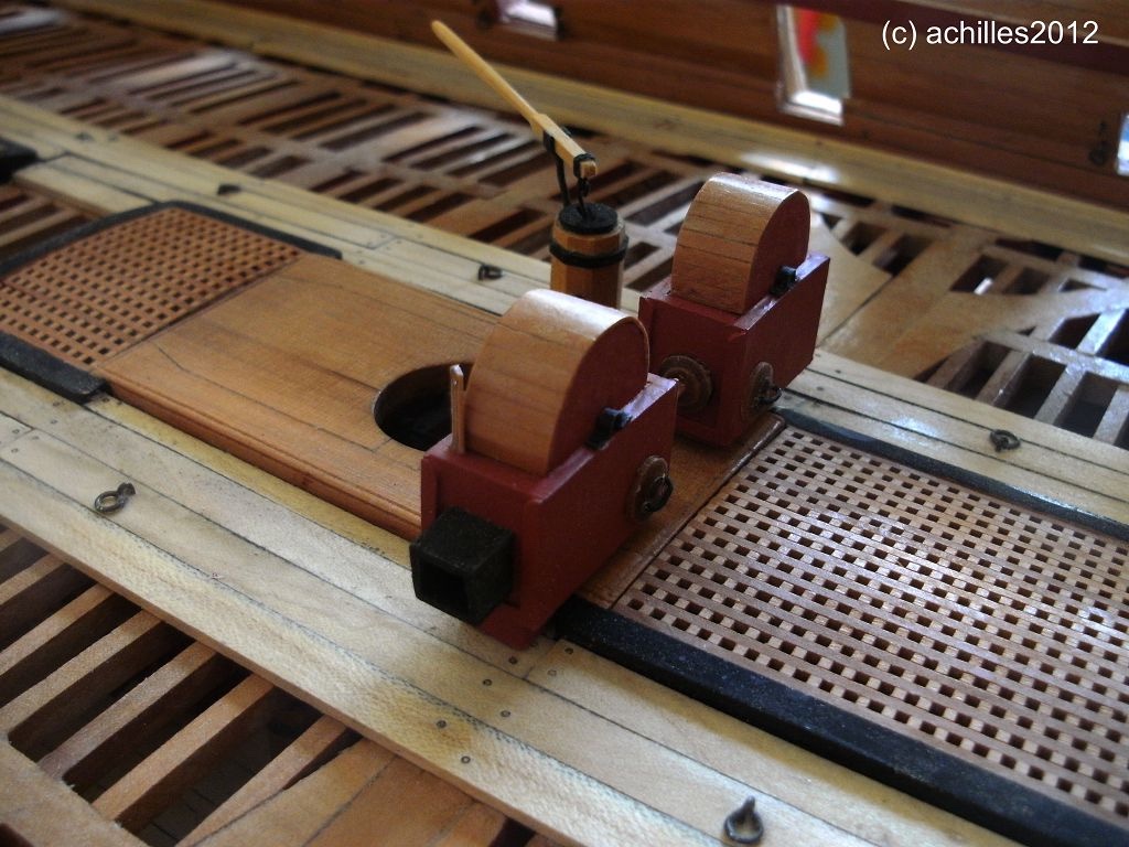
Also nicely to be seen the different openings on the cistern casings to interlock them or give extra discharge possibilities.

ZAZ0157
XXXDAn
PS: A picture from this truly wonderful model was taken, when I was allowed to make the layout for the cover of Joachim Müllerschön´s (MSW Nickname: Schiffebastler) most interesting book about the Color Blue in historic Shipbuilding 🙂

-
My understanding too is that the single one is the elm tree pump. Often they were fashioned in this octagonal shape, with the hole in the middle. They served as fresh water pumps for multiple purposes.
If I can distinguish properly, one of the plans show the Unite with the 4 french pumps that were single wooden tubes with a metal joint in the middle.
ZAZ3181 https://collections.rmg.co.uk/collections/objects/82972.html
The decks plan fits to this
ZAZ3183 https://collections.rmg.co.uk/collections/objects/82974.html
The deck plan is in this sense strange, as this pump would be to near the bit. Also the fore and aft hols are shown different.
ZAZ3184 https://collections.rmg.co.uk/collections/objects/82975.html
This side elevation shows a different pump than usual and a curved pillar. Could this be a hint. I can´t distinguish the front one due to the resolution:
ZAZ3182 https://collections.rmg.co.uk/collections/objects/82973.html
XXXDAn
-
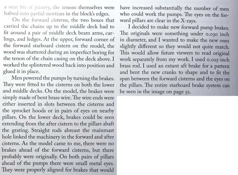
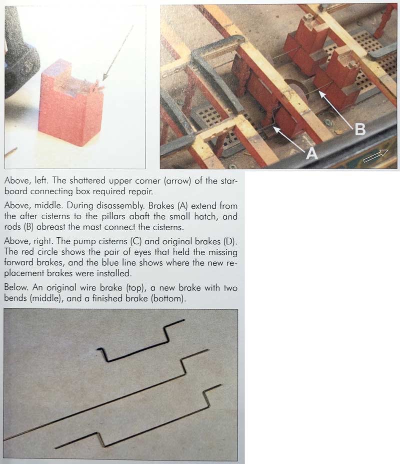
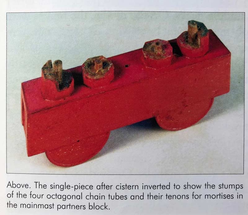
I hope it is ok, to sum up an overview to the remarks from Rob Napier in
LEGACY OF A SHIP MODEL
Examining HMS PRINCESS ROYAL 1773
Seawatch books https://www.seawatchbooks.com/ItemDisplay.php?sku=110002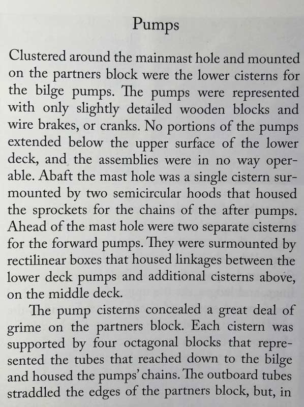
-
Thank you Gary, as usual many great and new input !
My understanding today is, that in our days the Vic in P. is equipped with a pump for two-deckers (third rate) or lesser vessels. As all three-deckers (First and second rate) of that age she should have a setup including one pair pump going to the middle deck as to be seen in the 1788 plans in NMM.
Chain pumps:
Let me sum up the open questions:
- Why not in the two-deckers? Benefits would have been the same. Probably the cranks would be in the way or the whole ensemble too exposed within the waist? It is here where the boats were stowed and sails were handled.
- Even though all the hints known to me suggest that the tubes from the lower cistern and the upper cistern were in line, the quality of the drawing still does not satisfy me, as they could contain simplifications. So still looking for the real technical way of working.
- What mechanics? Gary mentions the cranks on the lower deck not being used to turn the upper pump. Are there any proves for this or is this still a working thesis?
- When and how was the exhaust on the lower cistern used? Every time that that scupper was not submerged to save height and therefor work?
Elm tree pumps
In my model I still have at the moment the 3 elm tree pumps going up to one deck each. The 1788 deck layouts and the model of HMS Queen suggest that there was one pump ending in the lower deck, two ending in the middle deck and none in the upper deck (in contrast as seen today). Reason could be as it would be exposed to the elements as the waist is open at that space. So I would shorten that long pump on my model.
All the best, Daniel
-
*push* 🙂
As I am working on this topic, I just bring it up again to see, if anybody has new thoughts or even evidences.
Let me sum up the thoughts so far.
Until approx. 1760 all major ships of the British Navy - First-rate, Sec.-rate, Third-Rate, forth-rate - had a set of 2 pair of chain pumps in the lower gun deck. So far, so good. This is also shown in all standard literature, contemporary and modern ones.
Afterwards this setup was only for two-deckers and lesser ships, three-deckers got a new set-up for their chain pumps.
In the first step plan showing the inboard profile of three deckers show one of the pair of pumps - mostly the forward pair - extended to the middle deck, showing something like a coq wheel and a turning handle. See NMM 'Sandwich' 1759, 'Barfleur' (1768), 'Princess Royal' (1773). This gives the impression that it was only to provide more manpower and no transport of water.
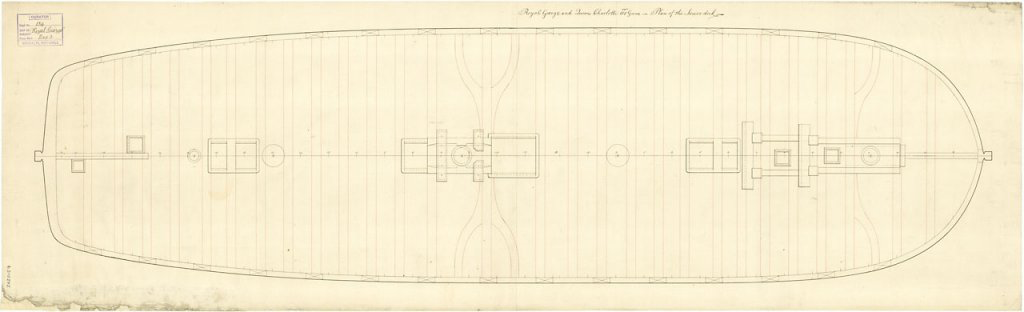
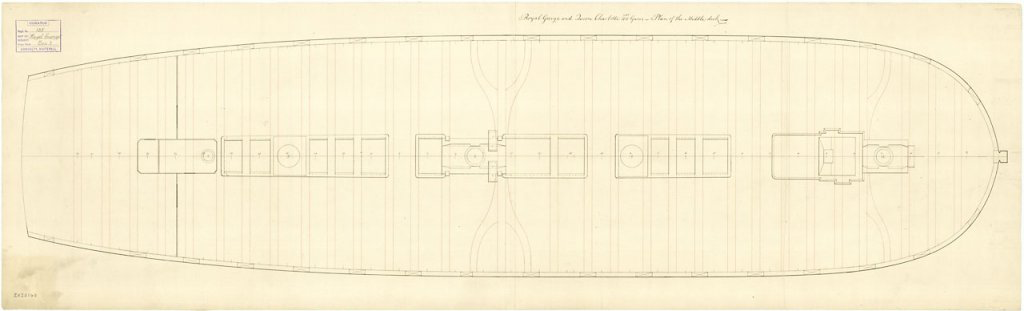
Next step was that in the middle deck got an extra cistern with an exhaust outlet (if the level of details of the drawing show that). This suggests that the water was transported to the middle deck and drained from there. The cisterns in the lower deck all kept their outlets. 'Royal George' (1788); 'Queen Charlotte' (1790)
Final step was the full set of two pair of cisterns in both decks all with water outlets. 'Hibernia' repair 1821
The best guessed reasons so far:
- more man could man the pump
- the water could be discharged by a higher scupper if the ship was heeled in a way that the lower scuppers were submerged.
-
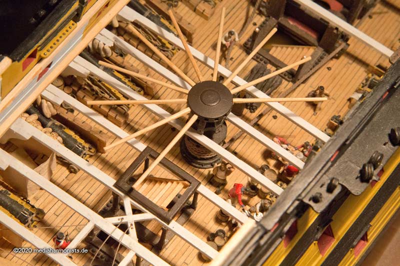
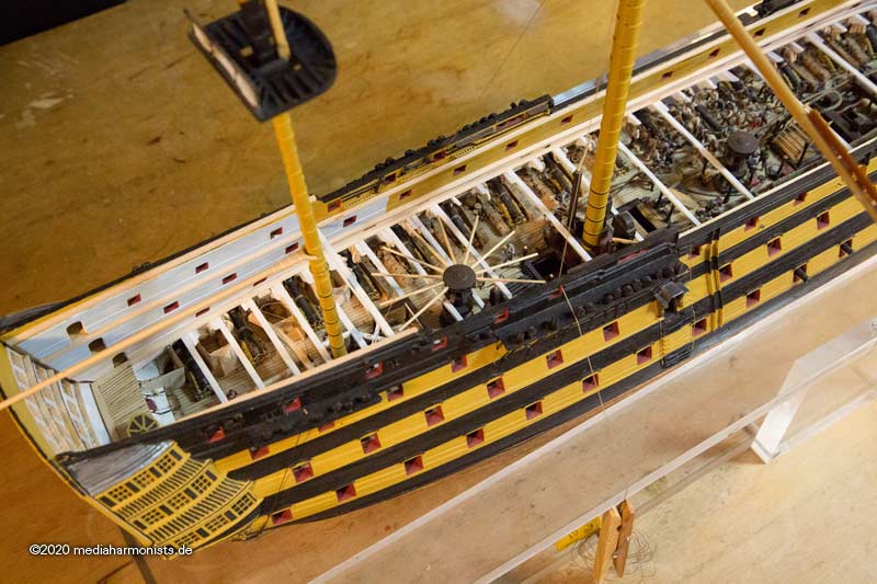
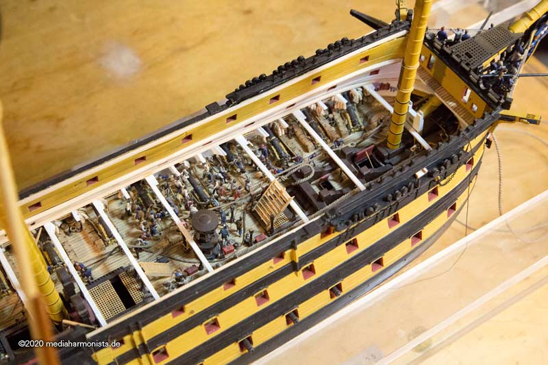
And here we go again.
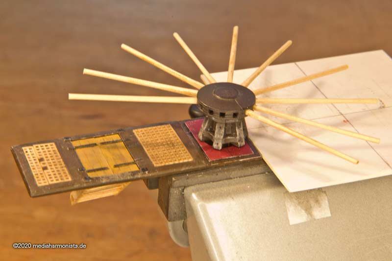
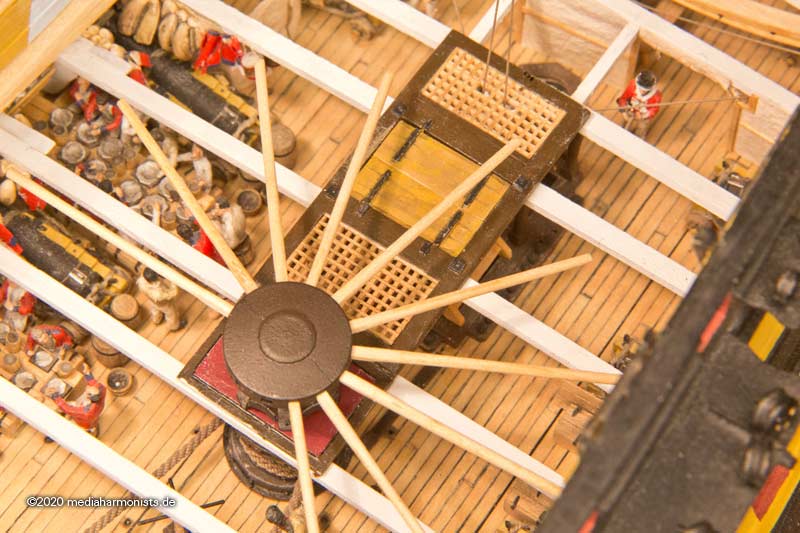
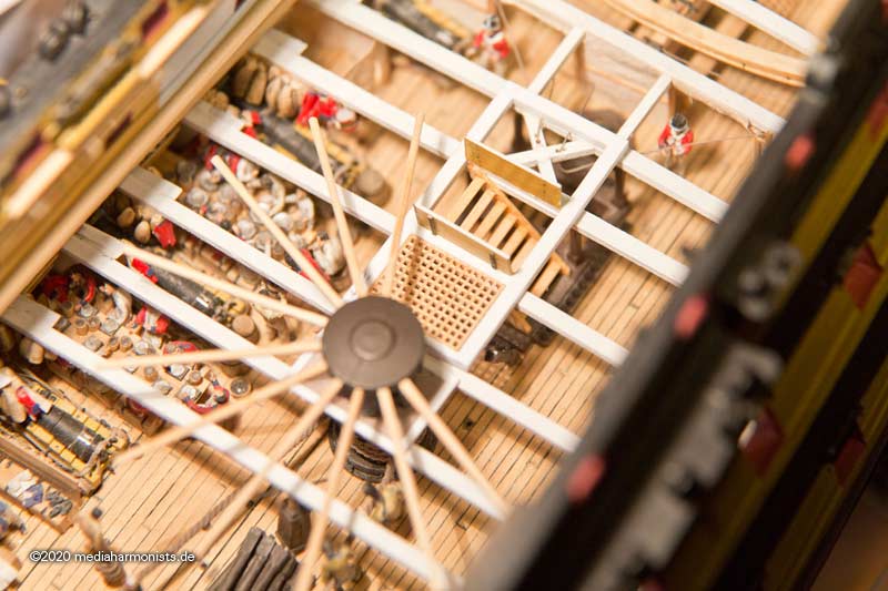
Short positional test of the guns in interaction with the capstan.
Guns run out ...
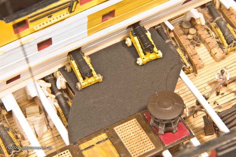
... stowed ...
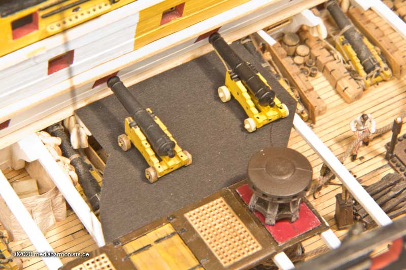
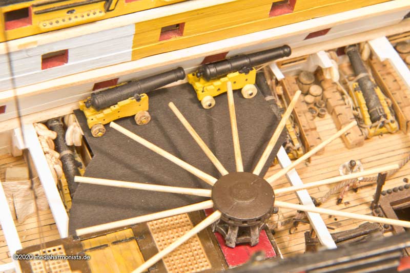
... cleared out of the radius of the capstan bars.
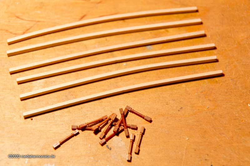
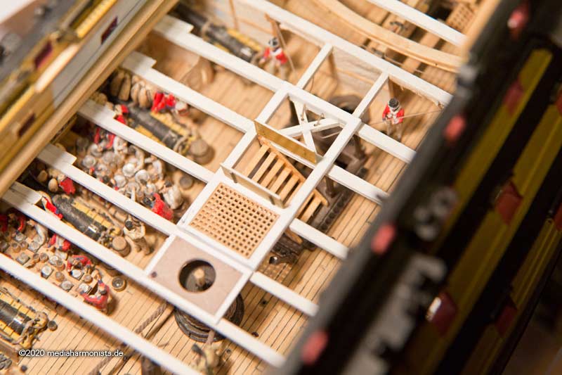
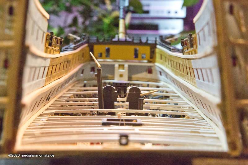
The next stages of construction will require the missing deck beams. Here is the status. The missing beams give a spaciousness and light that never existed.
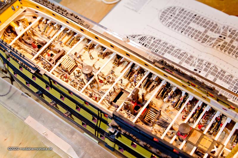
Beams pre-bent in a template. Supports prepared. Yes, you might be amazed, actually these are parts of the kit 😉
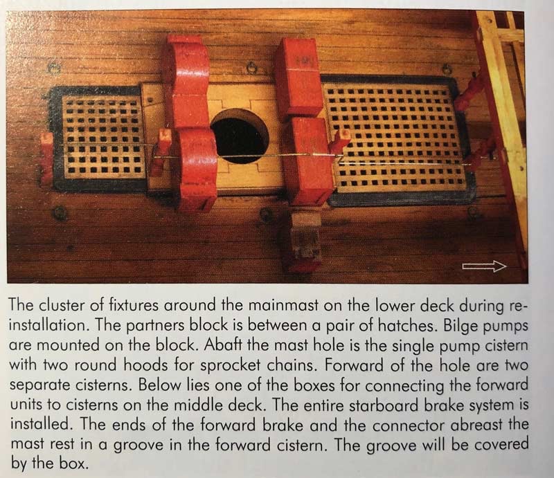
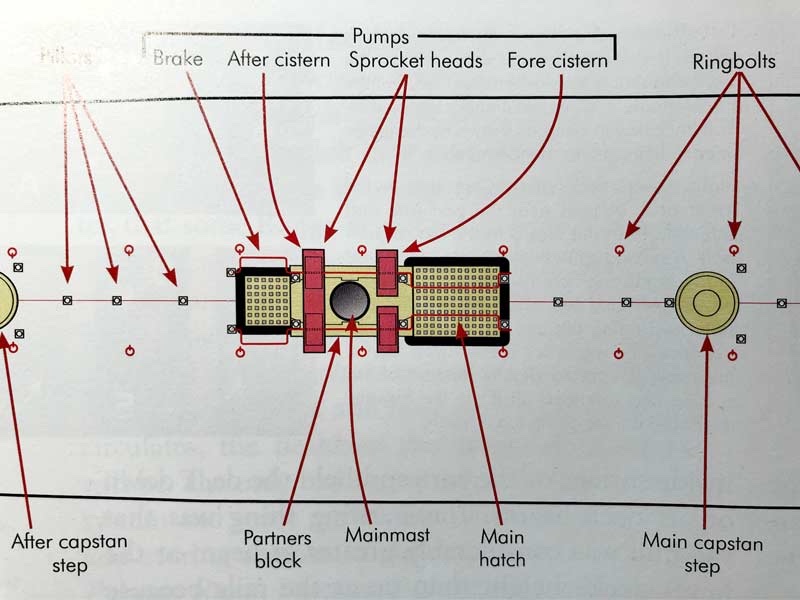
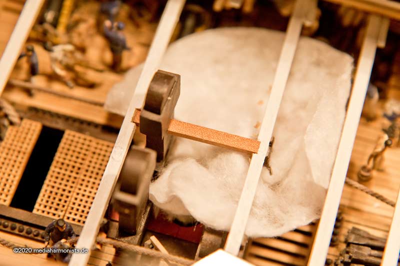
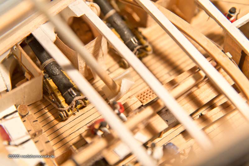
Because of the main mast, no deck beam can be set at this point. Therefor, two strong carling bridge the gap and also give guidance to the mast. But alas, there's my double-deck pump in the way. This mystery, the haunting specter of all plans between 1790 and 1860.***
***
Either the mast does not fit through ...
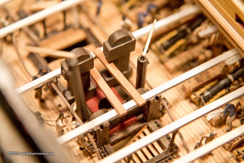
... or they are too far apart.
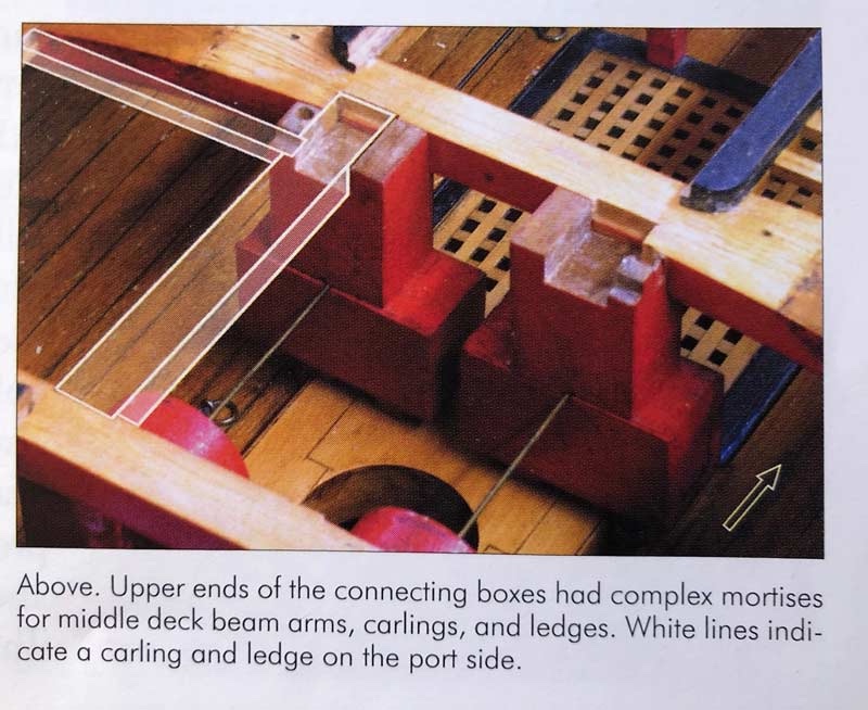
A quick look at the model of the Princess Royal reveals that the pump cases are built around the carlings, so one inner tube lies to the left and one to the right of the carling.
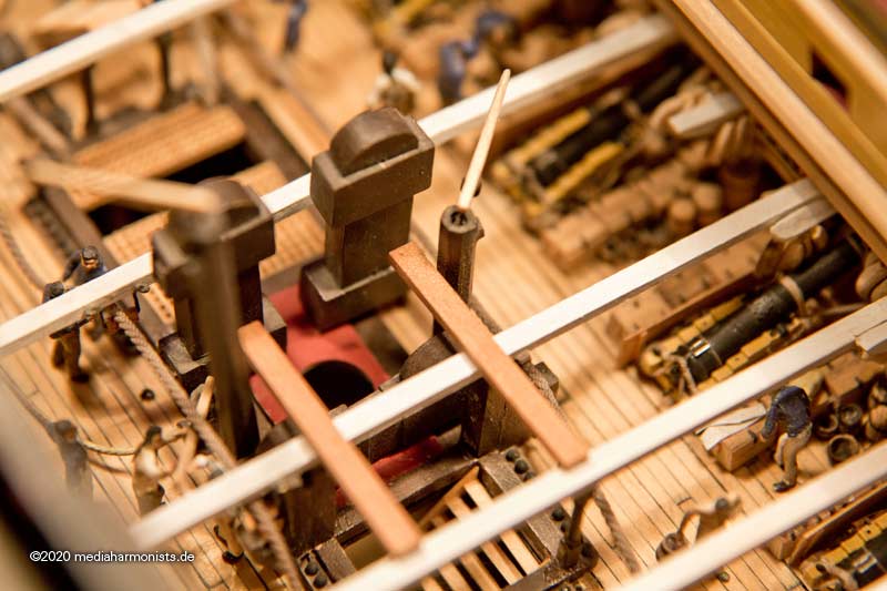
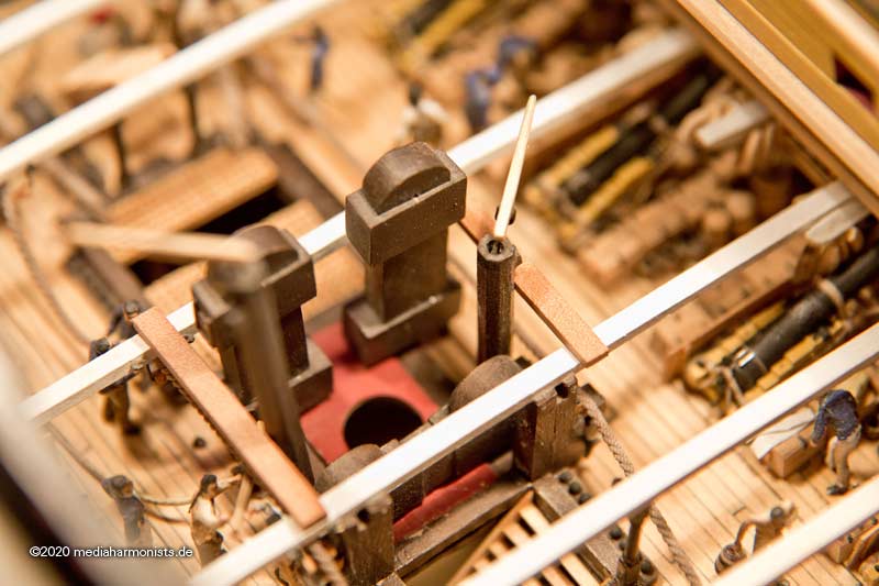
So pump torn out, a through hole was dug into the case, carling fitted.
A cotton pad was put as dirt trap underneath and the groove for the carling was carved.
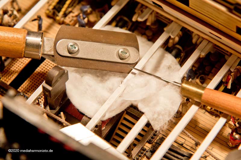
And done.
XXXDAn
- rybakov, druxey, BLACK VIKING and 8 others
-
11
-
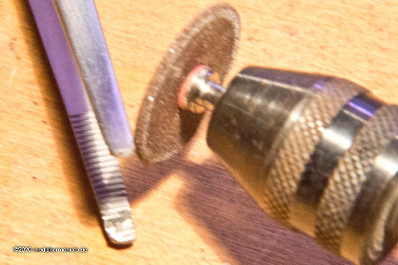
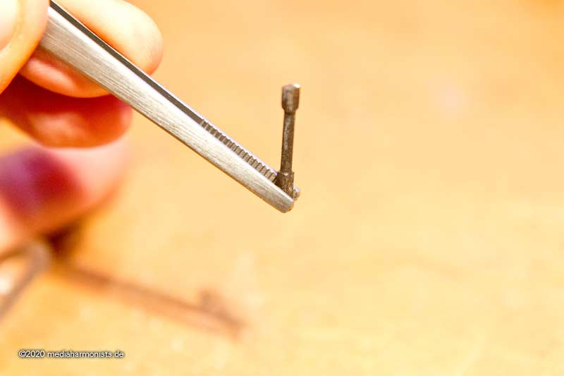
Small intermezzo - gadgets
Tweezers fitted with a small angled groove, so I can hold and place my deck pillars angled and canted 45°.
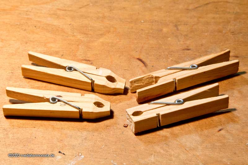
My collection of converted wooden clothespins is also growing.
And for works within the hull, always put a cotton pad underneath and the dirt gets caught.
Also no parts can escape down through companionways if sealed with cotton.
And if you need to get things out of obscure corners, the shish kebab with double-sided tape on its tip has proven itself - gets into places that tweezers have never gone before.
XXXDan
-
I always understood that those eyebolts on the outside were a french/continental preference. The english preferred just spikes on the inside for as far as I recall for impermeability and anti-rotting reasons. I remember once reading about a vicious comment about the all those frensh "iron ships".
XXXDAn
-
Thank you!
Profiling the coaming: First a slight curvature analogous to the camber, and then the edges rounded.
Still tinkered some more gratings, ...
 [/img]
... and all fitted together. Here in a closed state, ...
... and here open.
The whole set open in situ 🙂
Here the slots in the grating for the rudder rope.
And closed in situ.
XXXDAn
- Old Collingwood, druxey, Ian_Grant and 6 others
-
9
-
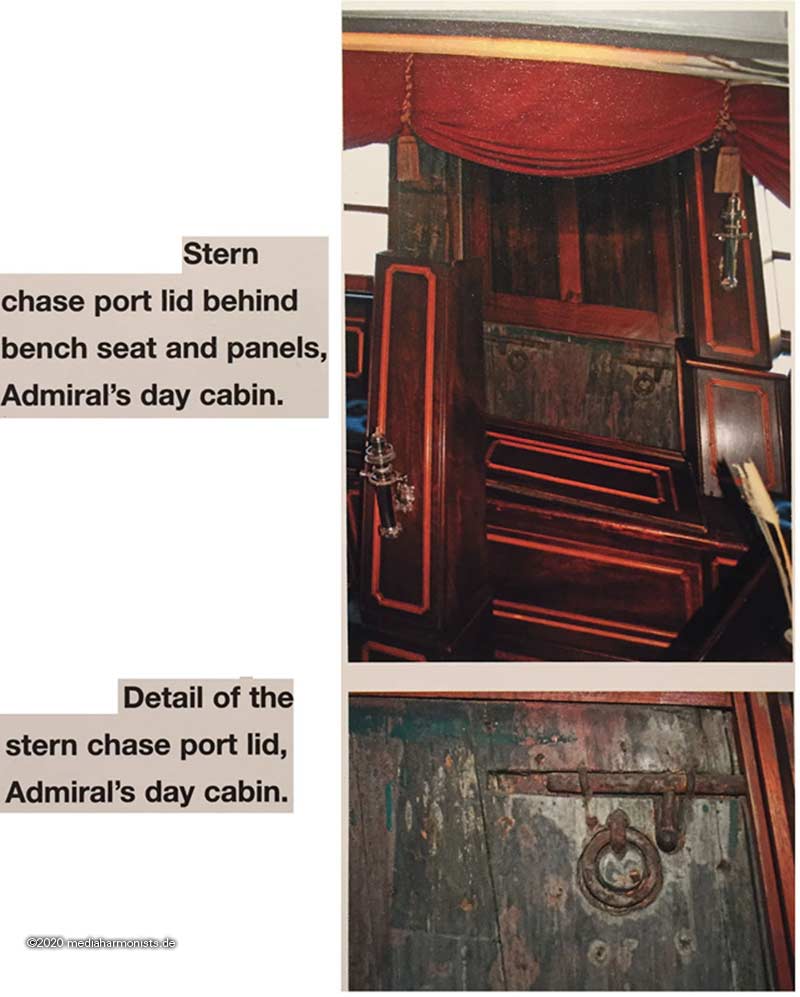
Here still on request as a supplement the hidden stern port from Goodwin's "operating manual"....
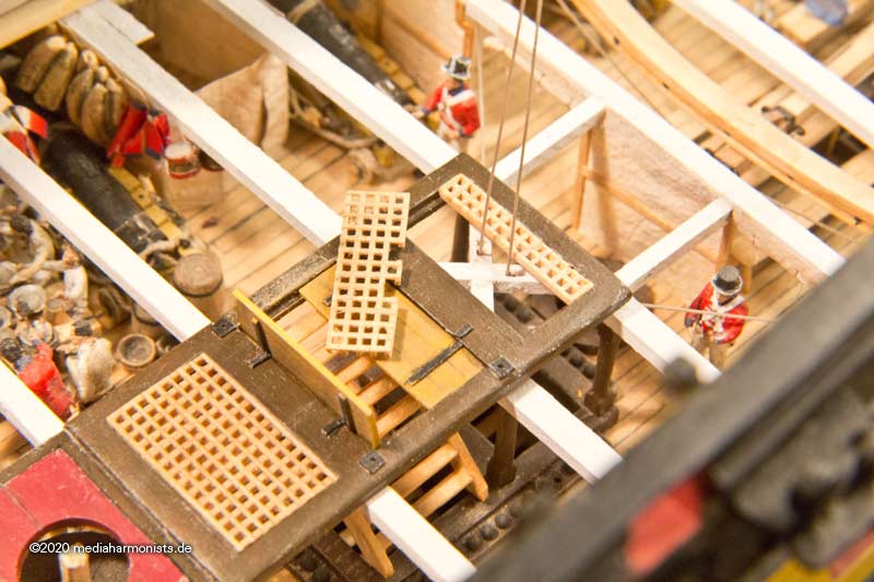
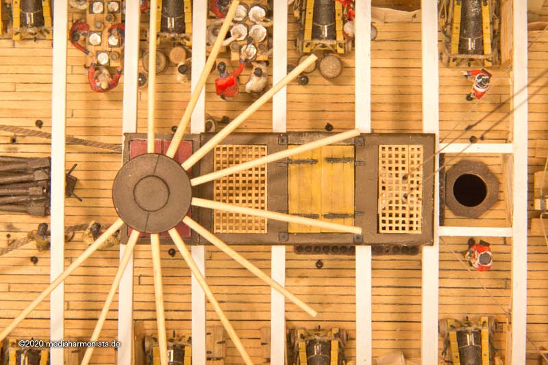
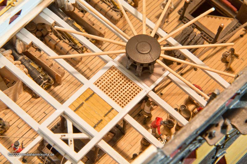
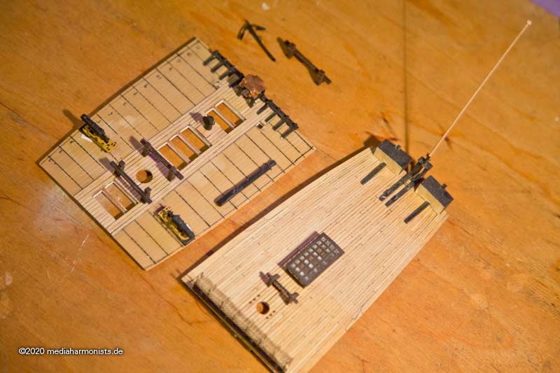
The other day - about 8 years ago or so - I had the companionway installed next to the capstan.
But as is so often found on English ships, there was a companionway just inside the capstan bars´ turning circle.
But how was this companionway closed when the capstan was operated? The first thing to notice was that the already made coaming on the model was not complete. As what do you do in such a case? One swings the blade ...
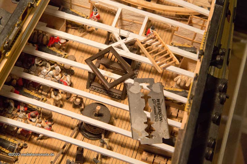
... and builds a new coaming 🙂
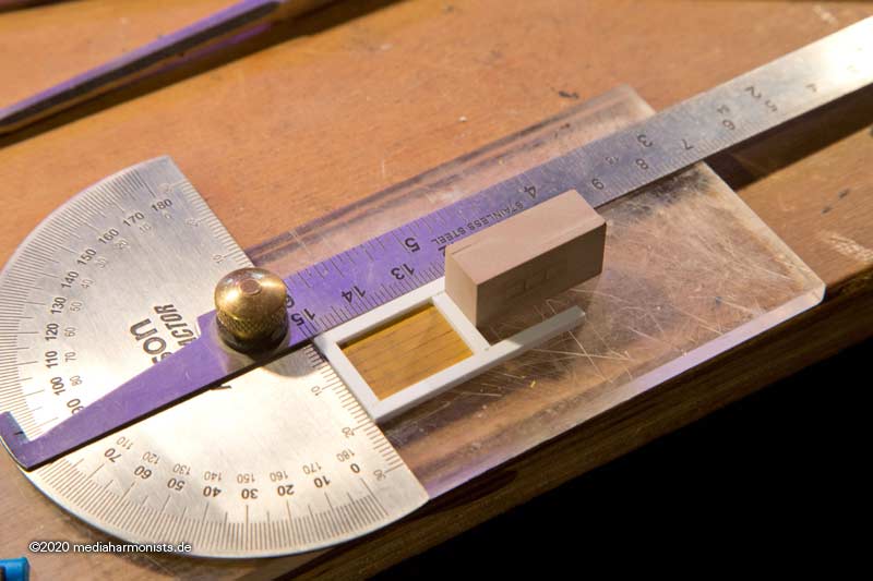
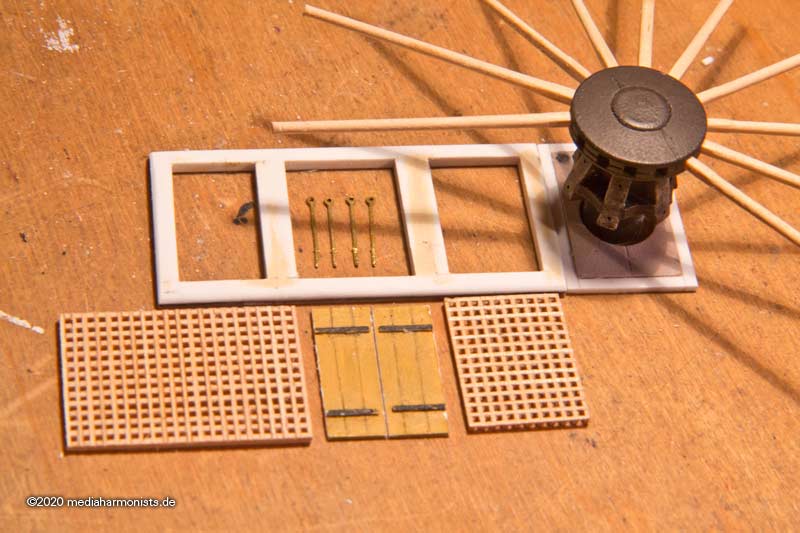
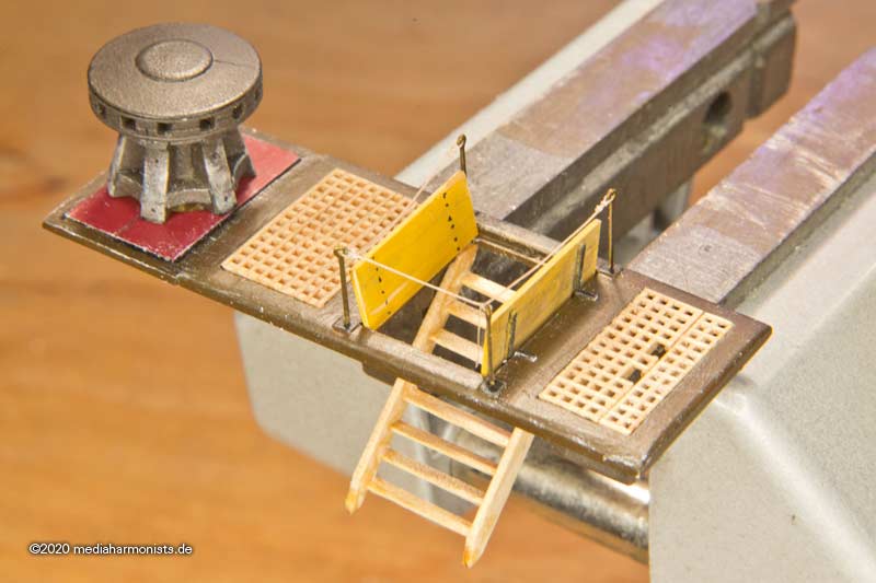
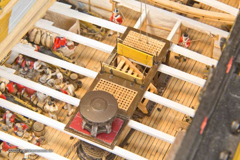
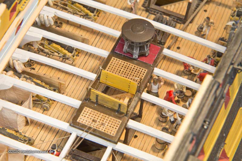
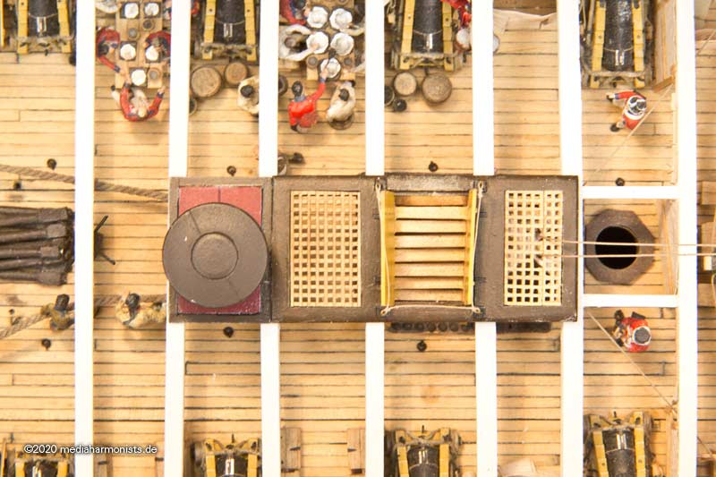
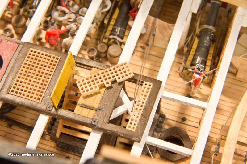
Of course, the sharp-eyed observer will not miss the fact that there is a small 90° twist here in coming n#1. So I had to do it again and here it is the new quadruple coaming combination, from left to right: In the first field comes the rope for the tiller cable, then the companionway, a free coaming and the enclosure of the capstan.
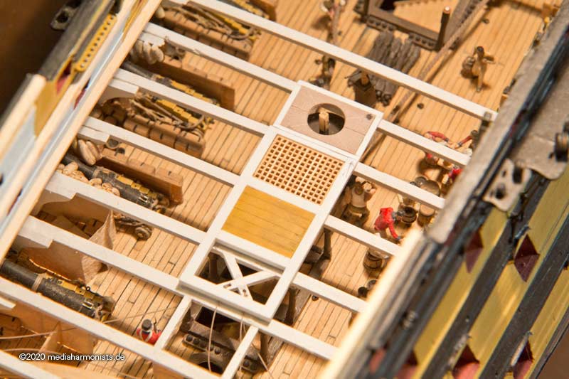
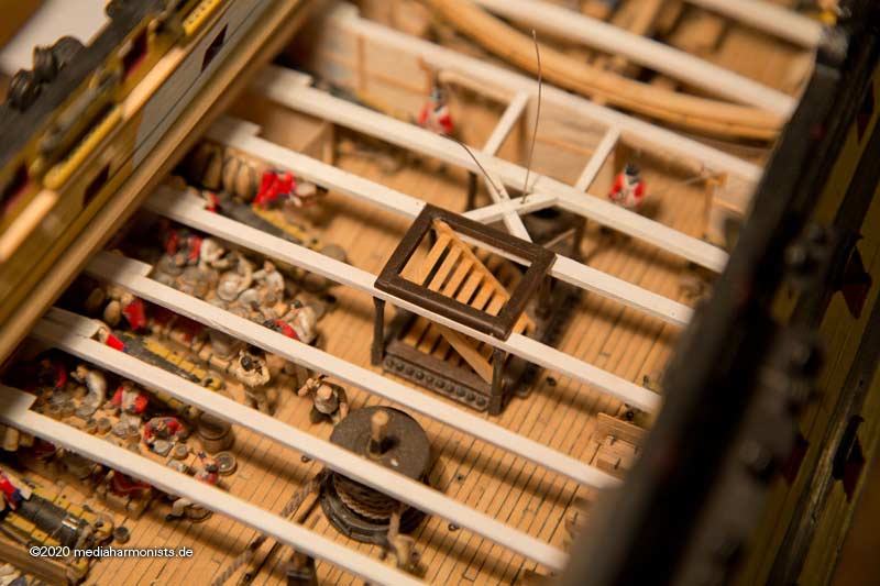
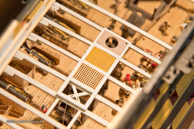
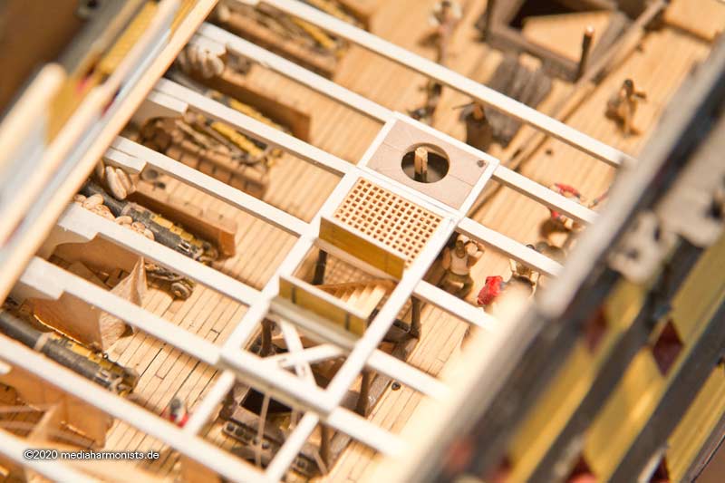
Today in P. there is a grating underneath the capstan. However, since the contemporary models I know have a solid two-piece wooden plate there, I decided to use one as well. The adjacent panel I have provided with a grating, so there can be a visual and auditory contact between the decks. The companionway here is covered by simply planks. Quick and effective to set up and clear away.
Possibly the companionway could also have been covered by a grating. Therefore I covered the field in the direction of the capstan with planks.
Or as seen on the Amazon class Frigate model in the NMM SLR0315 https://collections.rmg.co.uk/collections/objects/66276.html a double leaf flap. Very elegant solution. Closed it's good to walk on, open it also serves as a railing and doesn't need to be stowed anywhere else.
https://www.mediaharmonists.de/bilder/Sammler34/Victory-Spill-210120_6593.jpg
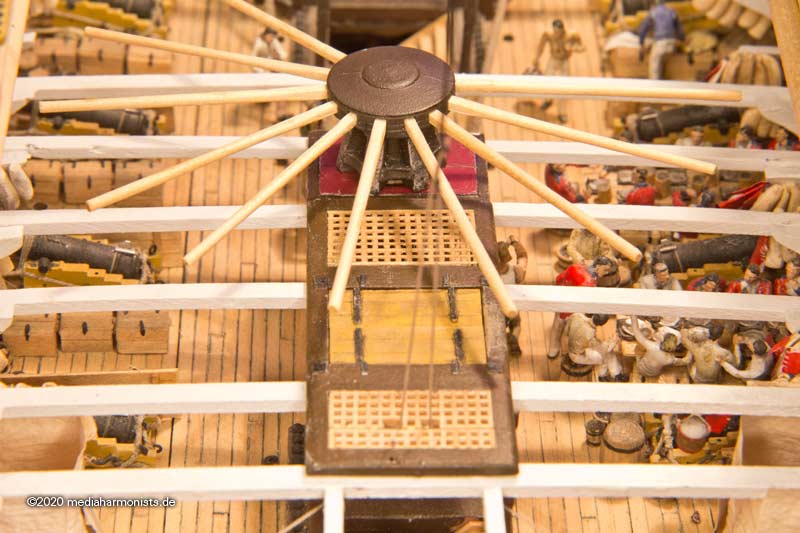
Also the flaps can be opened when the capstans bars are fixed.
Could this be a way of solving the mystery of how to close the companionway? ...
XXXDAn
-
In one of the posts shown above there is the drawing of William Rivers. He was on Victory from 31-05-1790 to 25-01-1812. Is it known to when dates the drawing?
XXXDAn
- mtaylor and thibaultron
-
2
-
My guess would be that if bent not by explosion but by the fall. But as the lower part is perfectly straight I would guess it is by design.
XXXDAn
- mtaylor, trippwj and Keith Black
-
3
-
Back to the conductors 🙂
We had a good discussion about the theme in our german forum:
https://www.segelschiffsmodellbau.com/t1912f643-Blitzableiter-an-Schiffen.html
Also NMM has nice exhibits 🙂
http://collections.rmg.co.uk/collections/objects/63401.html

REL0295 Main royal masthead from French flagship 'L'Orient' which exploded during the battle of the Nile. Lord Minto mentions it on display at Nelson's house at Merton in 1802. Pine mast with an iron fitting, which contains a sheave to take the signal halyard. A brass lightning conductor inscribed 'L'Orient' is attached to the top, bent in a loop. The whole is fixed to a square stand. [It is probably more accurate to date it to 'circa 1795', since the ship was under construction in 1793 (when the British failed to burn her on the stocks at Toulon) and it was certainly made and fitted before the Battle of the Nile when it was taken up from the sea after 'L' Orient' exploded. PvdM 2/13] Date made circa 1798Also the museum in Amsterdam has a nice model equipped with one:

XXXDAn -
And in order not to frighten the suspicious and spoiled audience, we continue with another dismantling.
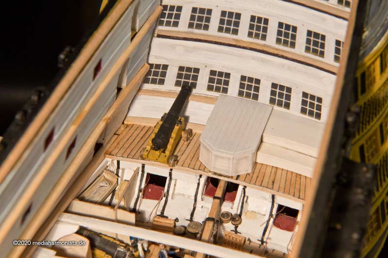
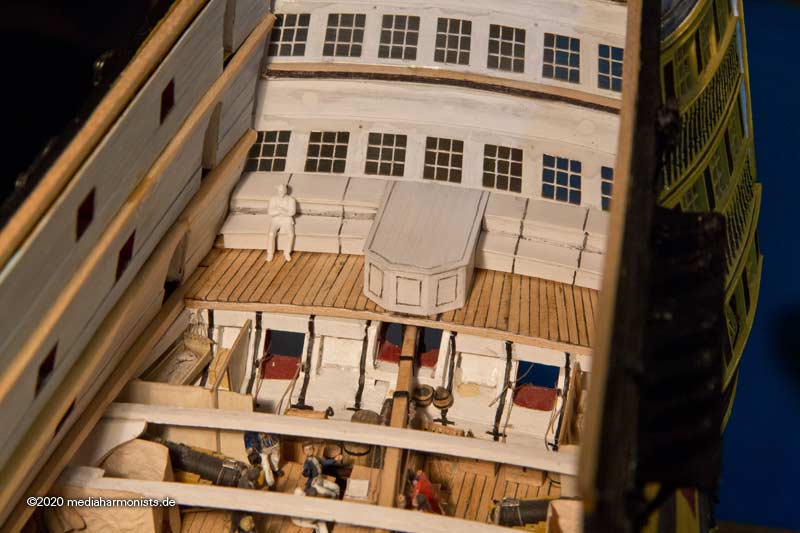
First, a look at the scene of crime, the middle battery deck.
The normal tiller is located in the lower battery deck under the deck beams. The picture shows in the foreground how the rudder head protrudes into the middle battery deck, with the slot for the emergency tiller in case the lower one is damaged. Handy in times of storm and battle.
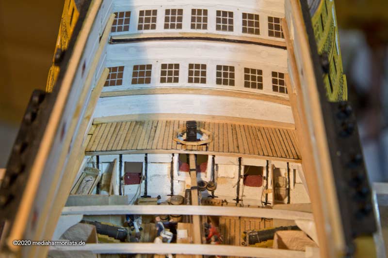
On the Vic in P., the rudder head is covered with an 8-cornered oval cowl. So far I haven't found such a part in the contemporary records. The contemporary model of the Princess Royal and other models show a cowl that goes all the way to the rear seat under the windows.
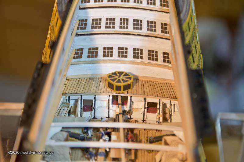
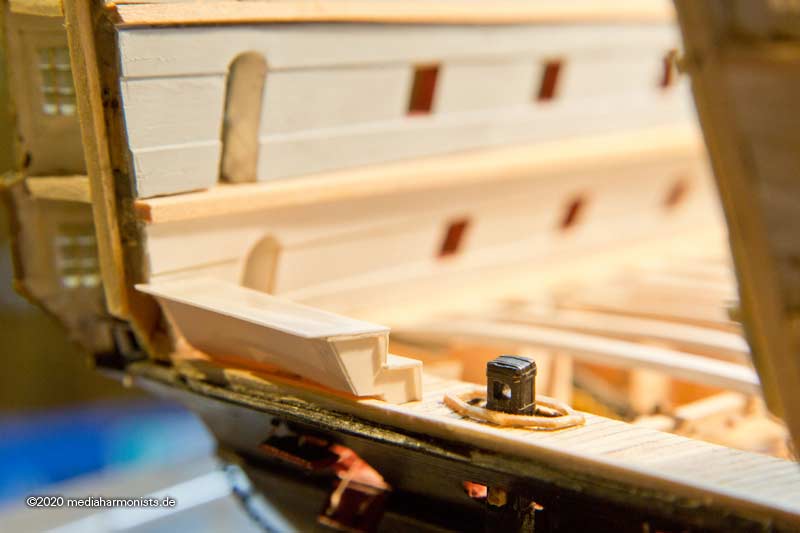
So snap away the current cover ...
... and new window seats, using a figure to determine the seat height, the total height was determined by the lower edge of the window.
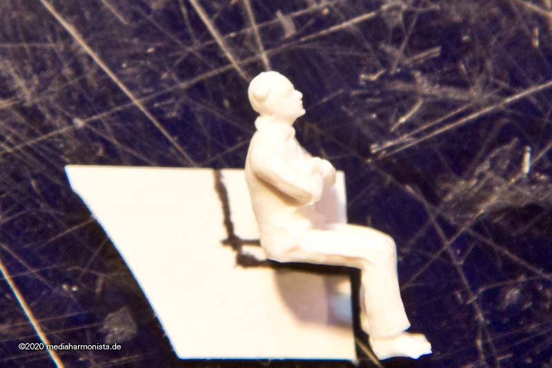
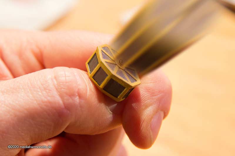
The depth is based on the model of the Princess Royale. After some fiddling, the cover and the two benches were built.
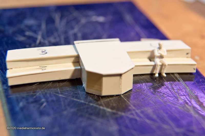
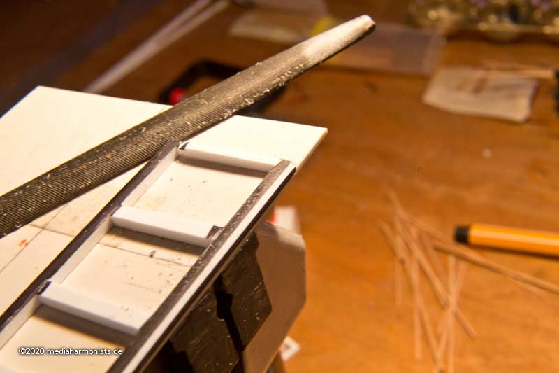
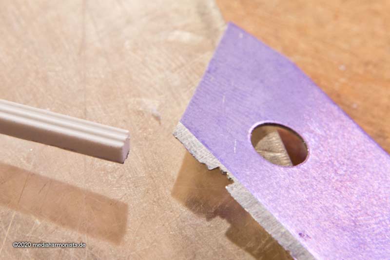
Another cutter blade was profiled to be able to score the surrounding profile ...
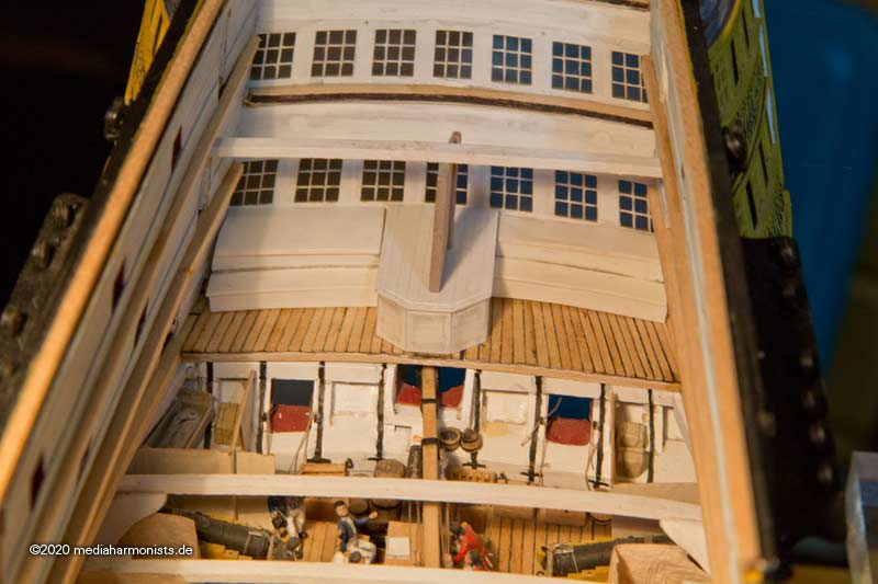
... and the whole lot adjusted in place. That's when the great depth caught my eye. Even though it was certainly used for storage, it was much too deep.
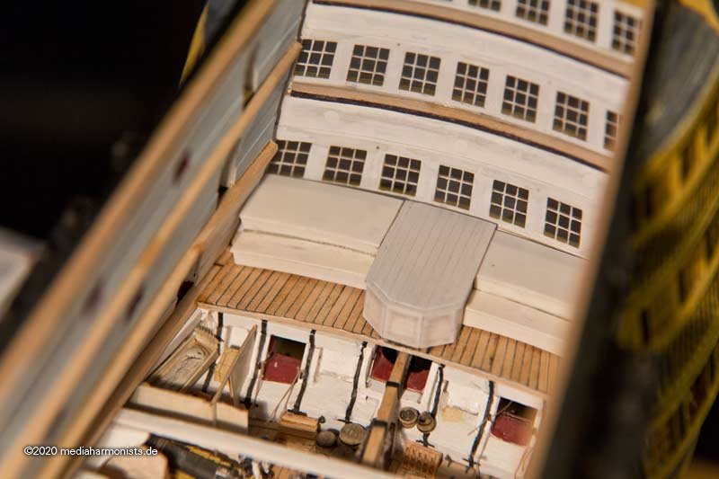
In case of battle, both the bench and the cover would have been dismantled to get to the hidden stern chasing ports. And you can see now on the gun how much space is wasted in this version with the bench.
Here again the rudder head ...
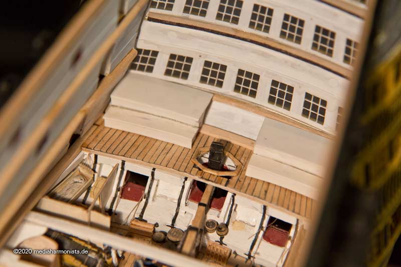
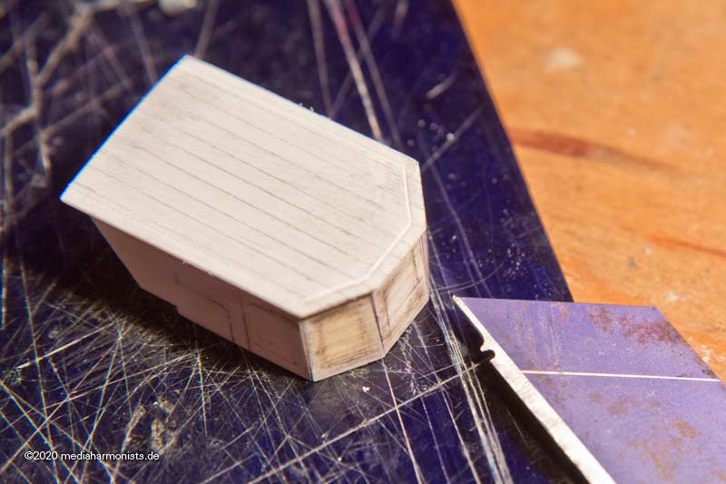
... with the slot for the emergency tiller. So I shorten the bench a bit in depth.
Here the port side has already been shortened ...
... and here the other side as well.
And our master is having a good time 🙂
Then another blade was profiled and a drawing iron made for the frame lining of the window frames.
And this is how it looks now 🙂
XXXDAn
- mort stoll, Baker, rybakov and 6 others
-
9
-
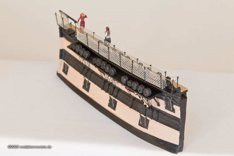
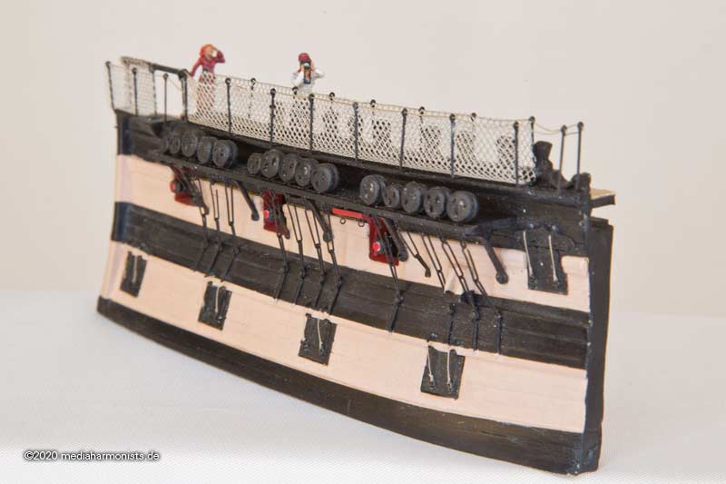
Before resuming the main trail, I had to clean and look for parts.
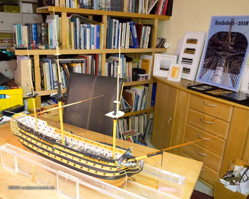
I was also asked how big my little one could get, and to my shame I have to confess that after more than 10 years I didn't even know ...
So I put in the jib, the flying jib and the gaff boom and hung up the mainsail yard with the stun´sail spars. So the dimensions were taken: 105 cm x 52 cm x 73 cm. Good that I know now 🙂
Here are some pictures of the actual state.
But you guessed it, setting main yard was not done so quickly. 1805 was in the middle of the war and Lees describes that the lower yard slings were replaced by chains during this war periods. As I had a piece of chain of the right length, this was immediately used for this purpose. But in the process it was noticed that the two scuttles for this were still missing in the main fighting top, as was the nailing ...
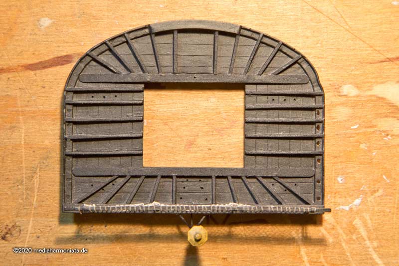
... so this was quickly done.
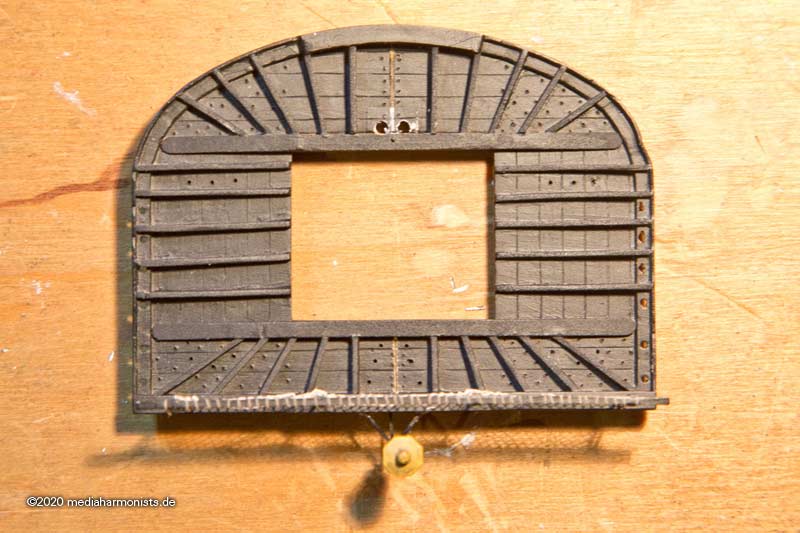
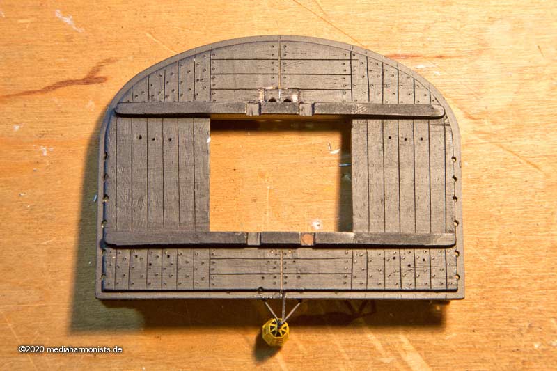
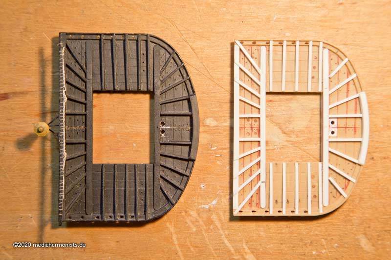
Here the comparison with the fore top: brown is the kit, white the new structure, as the tops were to be built in two parts from 1802 onwards to simplify repairs.
And then the main yard could be finally set, correctly with chain 🙂
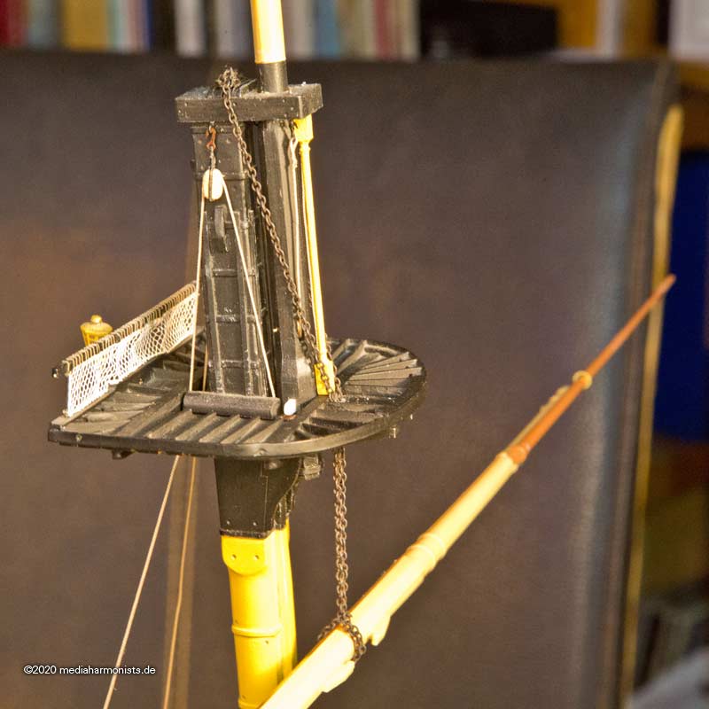
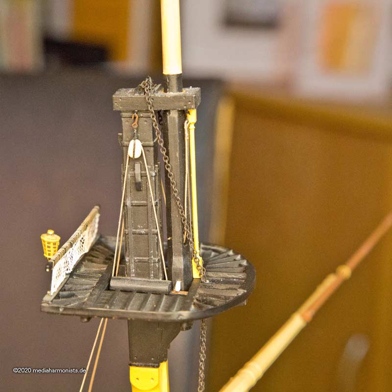
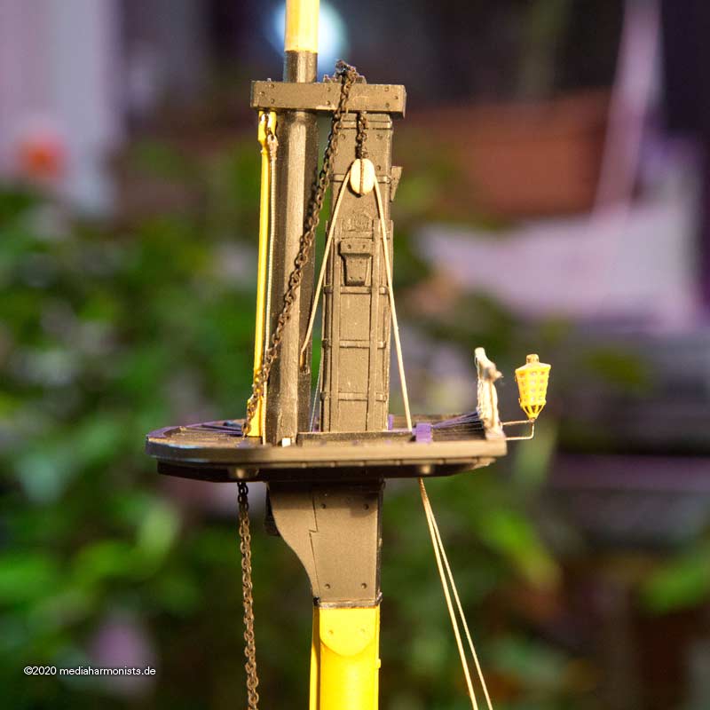
Note the following detail: On the starboard side, the stopper cleat of the square rig is shaped like a bow, as it is on the Vic today. On the port side it is formed as a shoulder, as shown by Lees, Schrade and some contemporary models. I have not yet been able to find out which variant was used when.
As always, questions about questions.
XXXDAn
-
Thank you SIrs!
Happy new year!
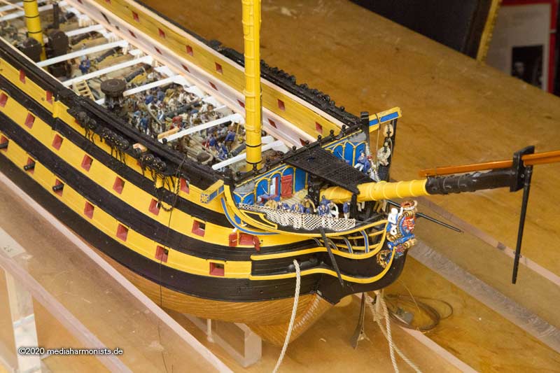
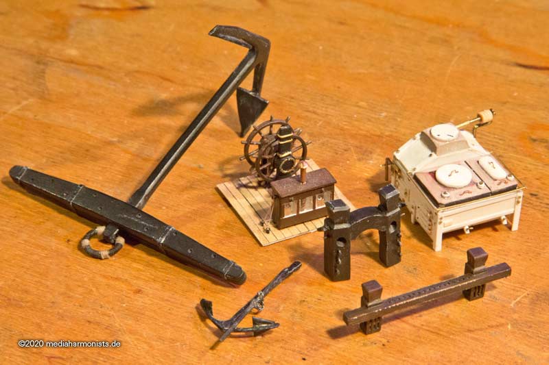
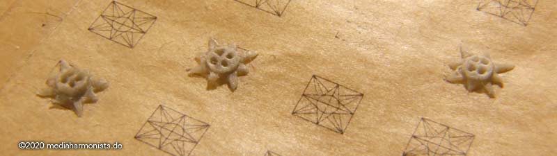
And what better way to celebrate than with a proper demolition, something I had already planned for some time. In September 2010, I was quite happy for one more rare occasion again, to be able to glue a part coming straight from the casting branch, just as the god of molds created it, directly to the model without pimping or without any further fuss.
See here it is, the little crown ...
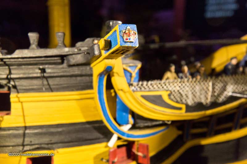
... by now I'm pretty sure that was not placed there around 1805. Probably an invention of 1920, when restoring to the Trafalgar state, for lack of better knowledge at that time. As the beam is called cathead, there usually was a cat's or lion's head on it in the initial phase. At the time of the Victory's construction, however, a kind of compass rose was common, sometimes also an anchor. Since the 1765 model of the Vic shows this compass rose and also the 1805 model, which was wrongly called "Victory", had such a rose, I felt quite confident to skip my sweet little crown with a light heart.
I made a compass rose out of modeling clay, and since the dimensions were tiny and tight, I printed the outlines on baking paper and was thus able to easily form to the true dimensions and to detach the fragile structure.
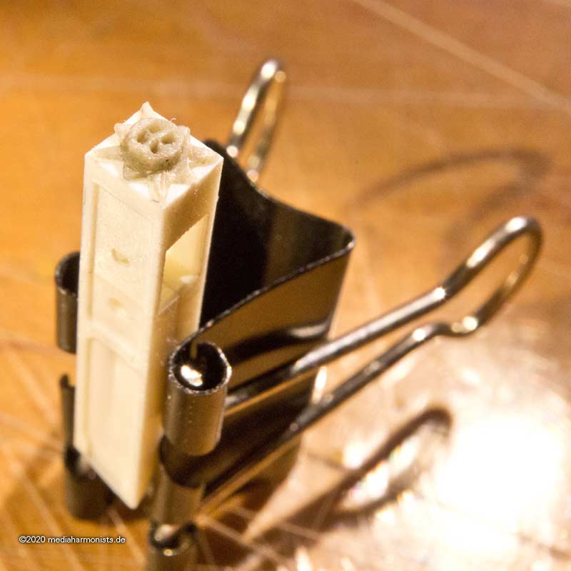
Once fit test on a replacement cathead with a specimen that proved too thick ...
... and I bravely swung the blade.
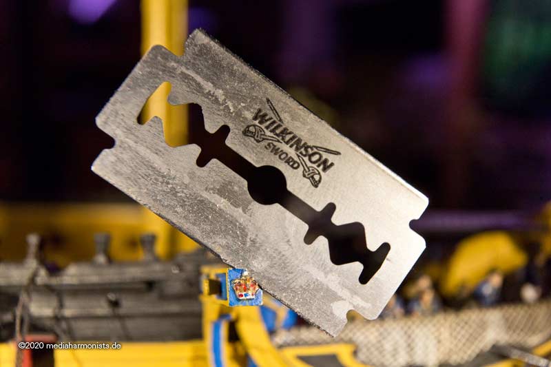
The new part was quickly glued in place ...
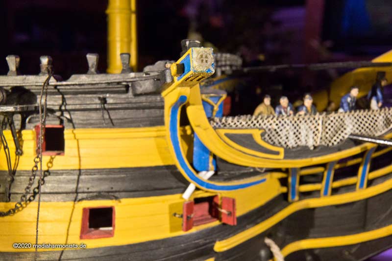
... and still a little paint was put on it.
And as a gif it gives a little impression of the depth effect. Enjoy 🙂
I know I've had other demolition orgies before, I just got out of practice 😉
All the best, Daniel
-
And last but not least the best known version, the ship as it stands today in Portsmouth.
Like new from the egg, no wear or tear, a nice museum ship as expected 😉
But even though all the anachronisms and contradictions towards the few contemporary sources still an amazing artifact that allows a bit of time traveling 🙂
But still I think no one today can imagine the true hardship and discomfort and dangers of those days. Physical, emotional and psychological.
Once a death bringing fighting machine, today it is a tourist attraction. Families and playing kids instead of powder monkeys and expendables wear parts ...
Here are some more details to enjoy.
But even this museum ship is undergoing the flux of changes. While bringing it back to the Trafalgar condition, the color "yellow" was misinterpreted and a cadmium yellow was applied, still to be found in many kits descriptions. Once it was understood that "yellow ochre" was meant the ship was changed to the buff seen on many contemporary paintings. Sometimes the chain irons were included in the stripe scheme, sometimes they were complete black. Newest research suggests a terra cotta tone for the hull, believing that the usual yellow ochre was short in the yard and the paint was stretched with red and white.
Also the hammock netting I saw already dark and light, the name on the stern I know in 3 different versions - even though I personally strongly believe it was omitted at Trafalgar for intelligence reasons - the stern davits were fitted in the past and taken down again. And much more ...
So this means, even if one builds a model of the museums ship, one has quite well determinate, what year it is meant to represent 😉
In this sense I might close this small side project and wish you all a happy new year! Stay healthy!!!
XXXDAn
PS: I still am waiting for those furious screams of panic once they adopt more research onto the ship in P., taking down the Feathers of Wales and the side davits, build the solid forecastle barricade and best of all, close the side entry port ...
-
In the repair of 1814 to 1816 the Victory was fitted with the new round bow and solid hammock cases. About 1837 the Feathers of Wales were fixed on the stern, still being there today. In 1859 the ship got the last set of wooden mast, later on the steel masts from HMS Shaw. Somwhere in the 1860 the planking was removed and the new planking was flush, wales omitted. Also that time she most possibly got the stern decoration that can be seen on the early photographies.
But these were only the outer signs, on the inside the hanging magazines were already removed by 1814 and every change in duty caused bigger changes in the internal layout.
There are hundreds of pictures of the pre 1920 Victory, an appearance that lasted more than a 100 years, but still this is one is the version that is the least often build as a model ...
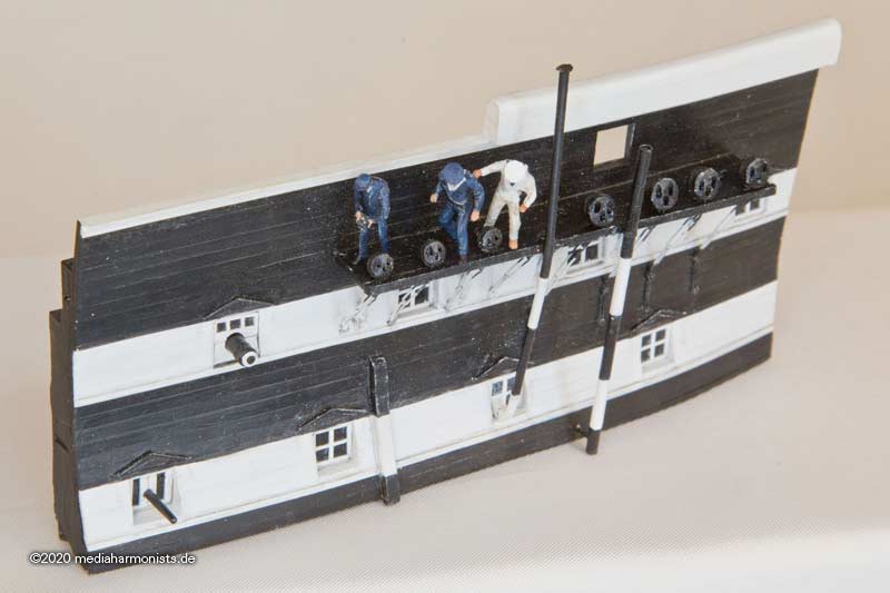
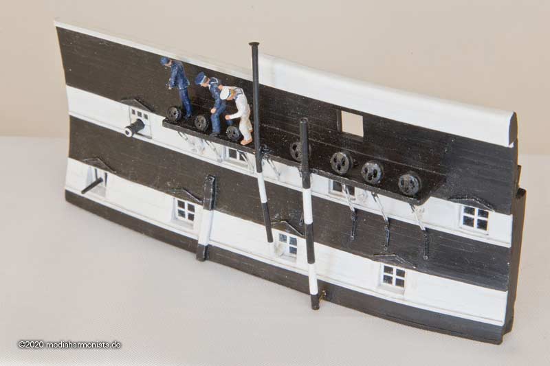
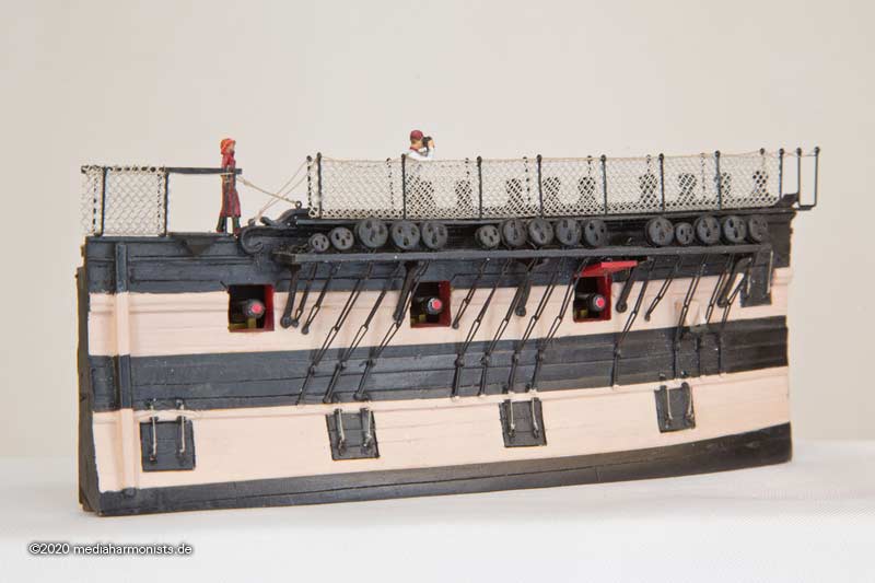
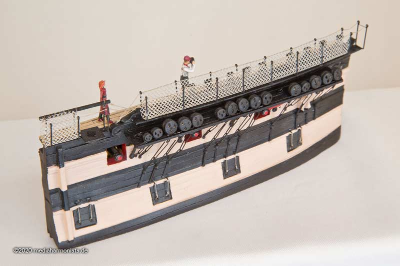
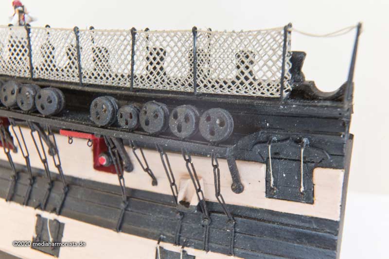
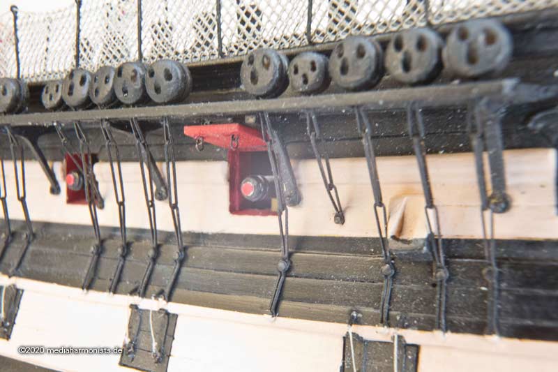
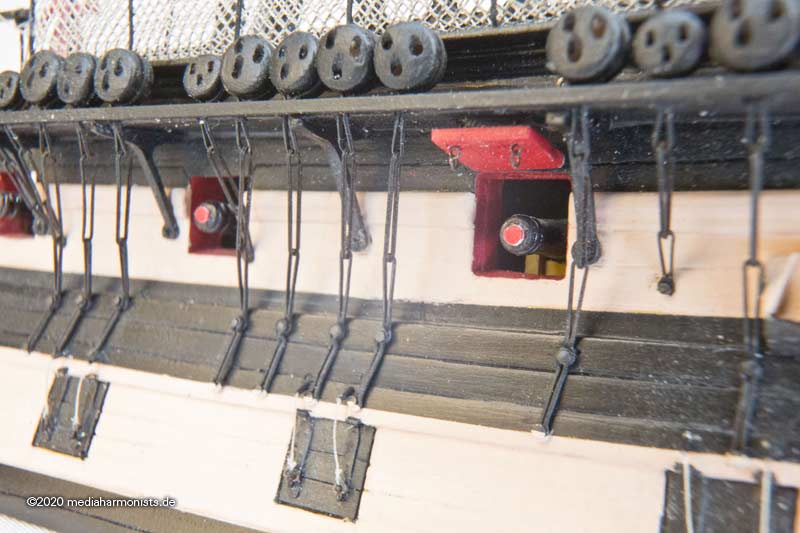
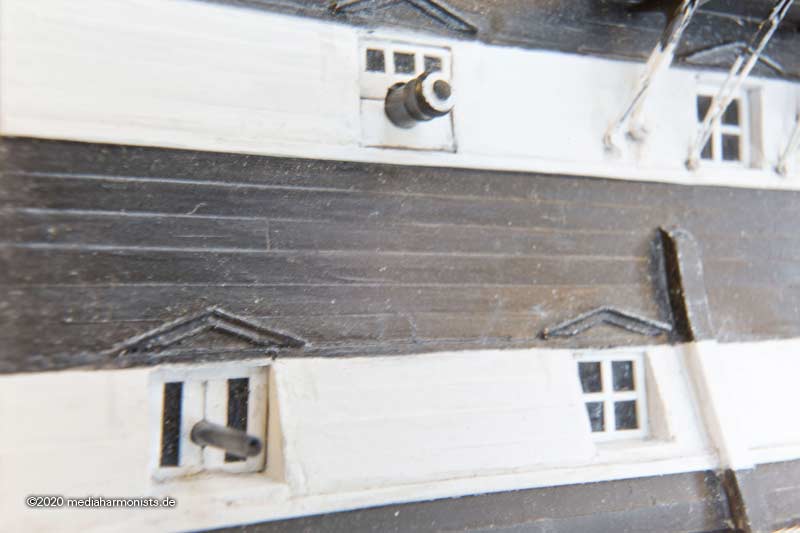
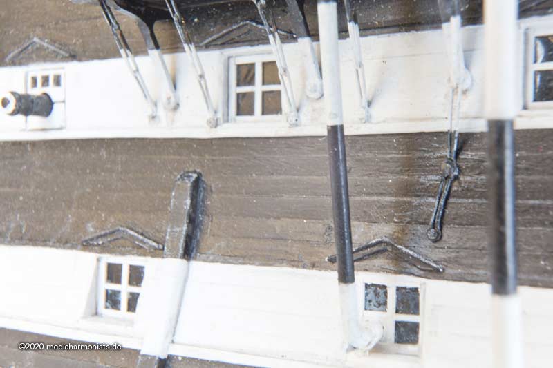
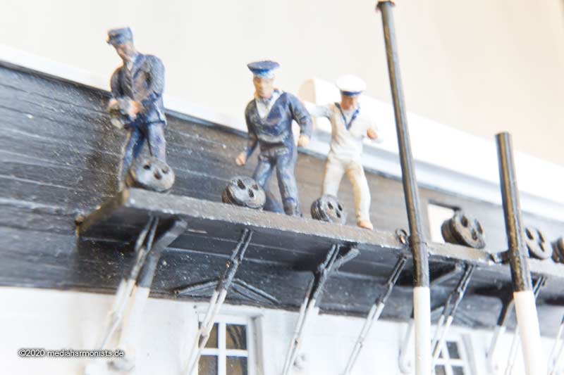
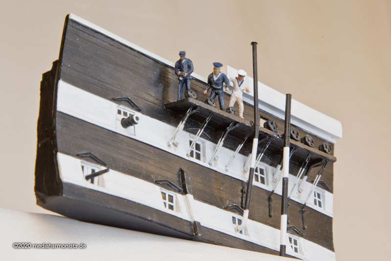
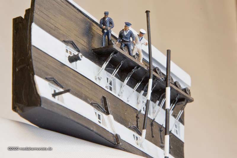
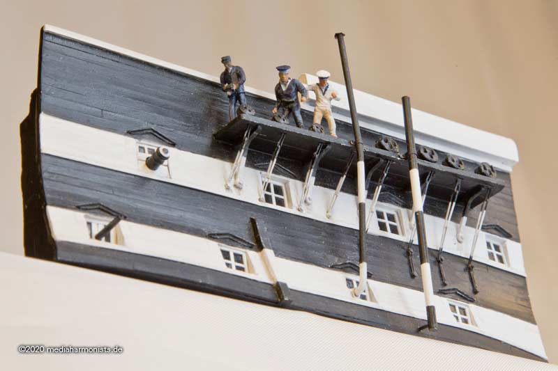
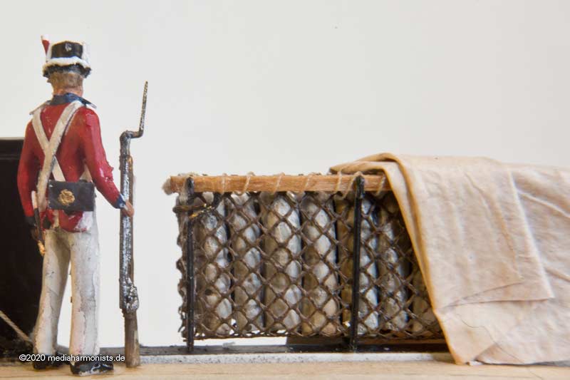
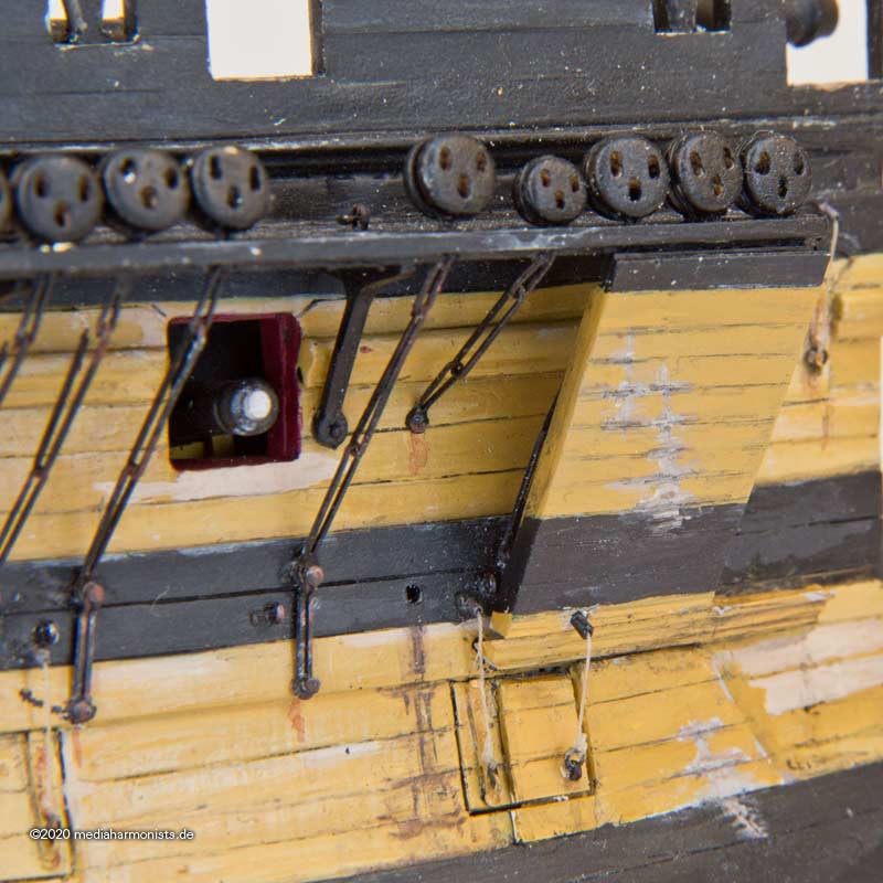
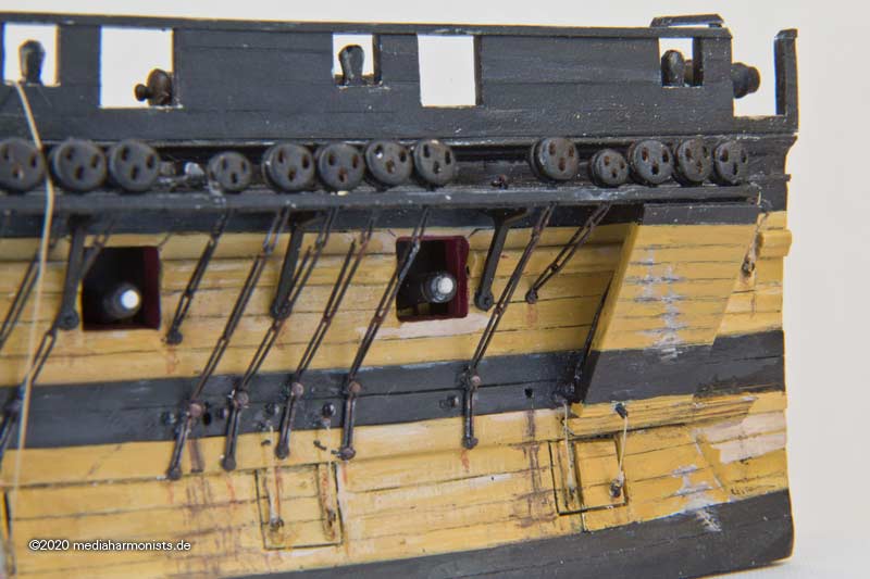
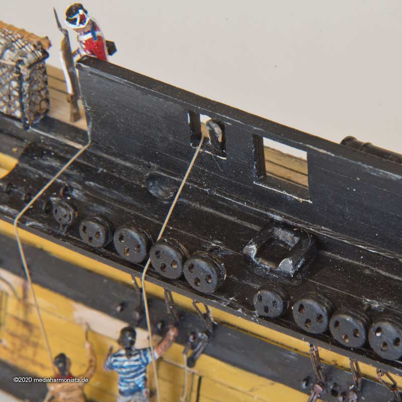
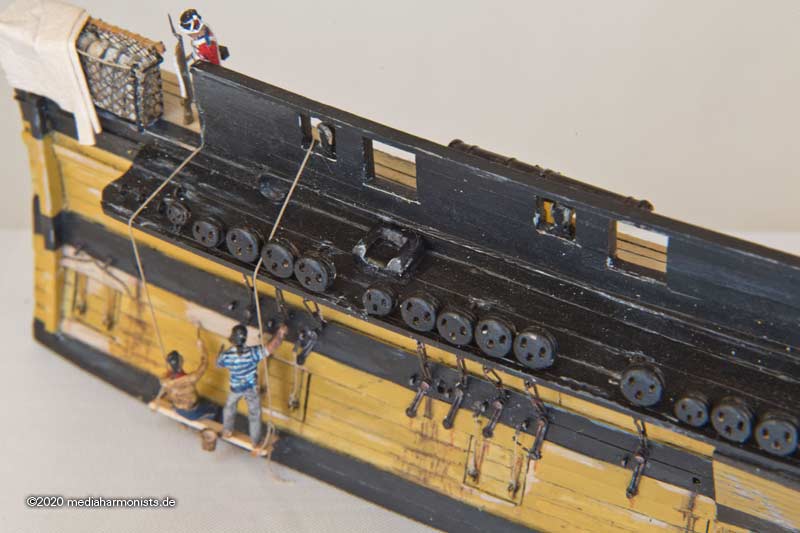
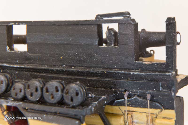
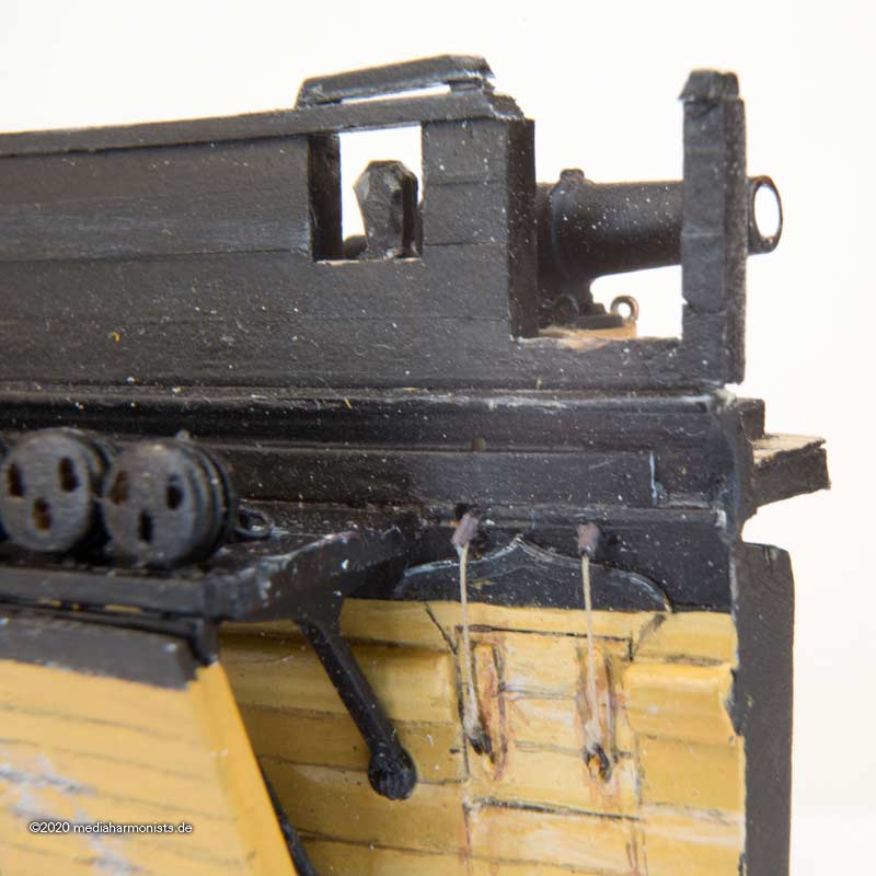
The planking was flush, the rigols were straight and the ports had window frames. In the upper and lower batterie there were still some historical guns from Trafalgar on display. In the middle battery there were 7 salute guns of modern design, 4 on one side, 3 on the other. The chain boards were shortened, the number of shrouds reduced. All along the hull there were waste pipes going down. Picturesque are all the stove pipes going up 🙂
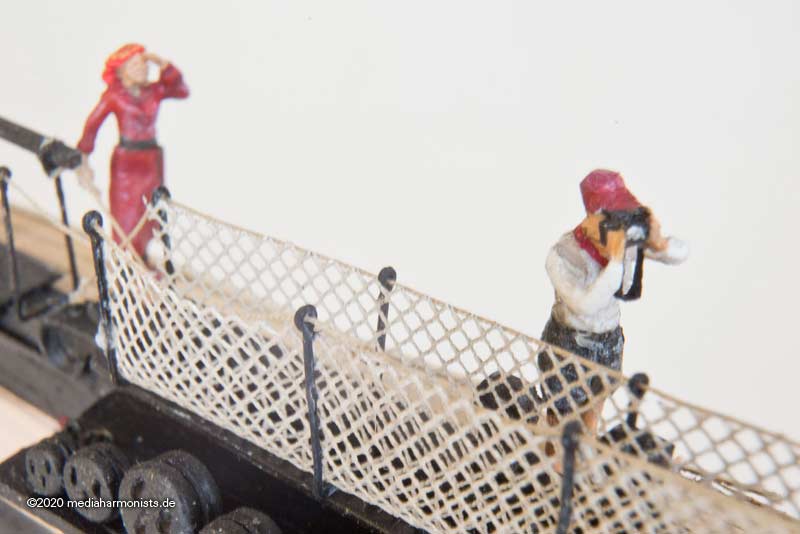
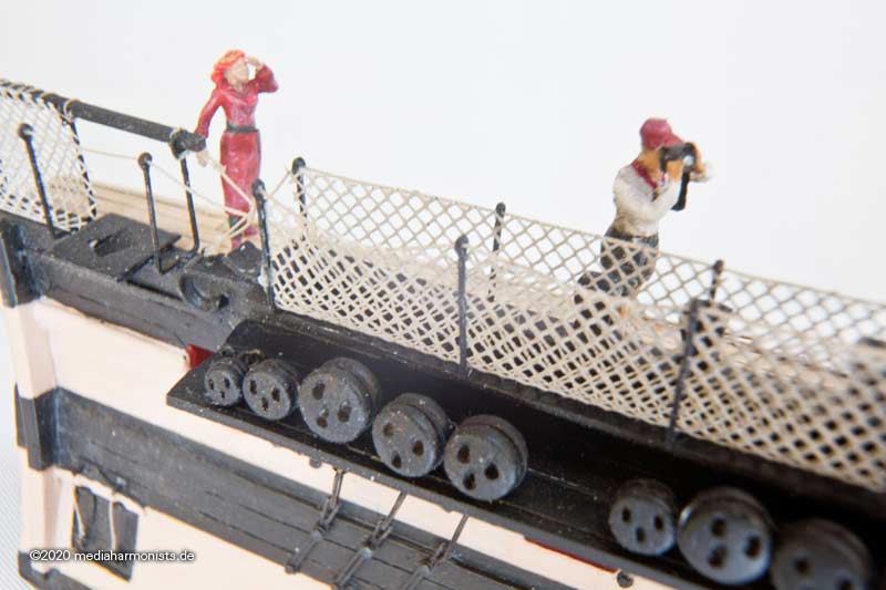
The officer is wearing a 1910 uniform with flat cap and short jacket, his camera is a contemporary Agfa-Photo-Box. The sailors have their uniforms with large hat and extra large collar, one in white, one in blue 🙂
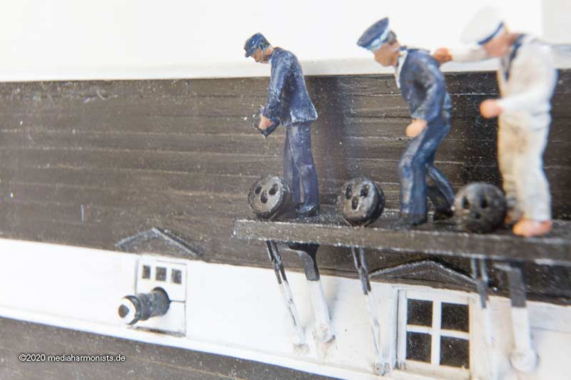
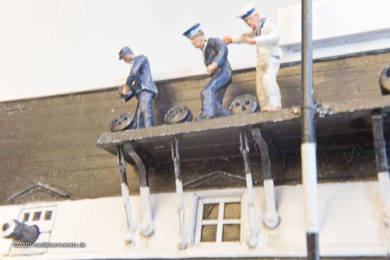
The inspiration for this scene is the sailor from submarine C34, looking up to the chains. In those days it was quite common for a submarine to be docked alongside, as their generators supplied electricity for the older ship.
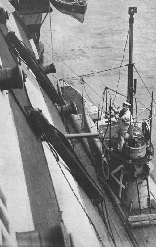
But was this sailor from C34 seeing? Possibly something like this.
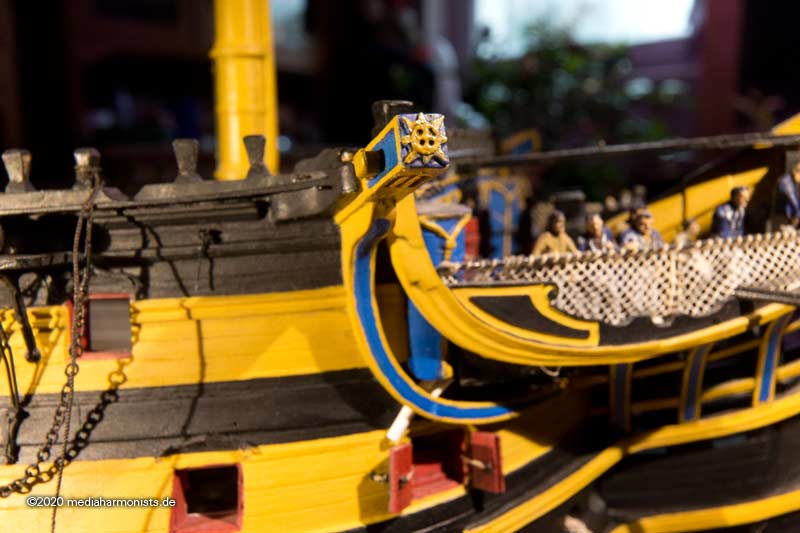
-
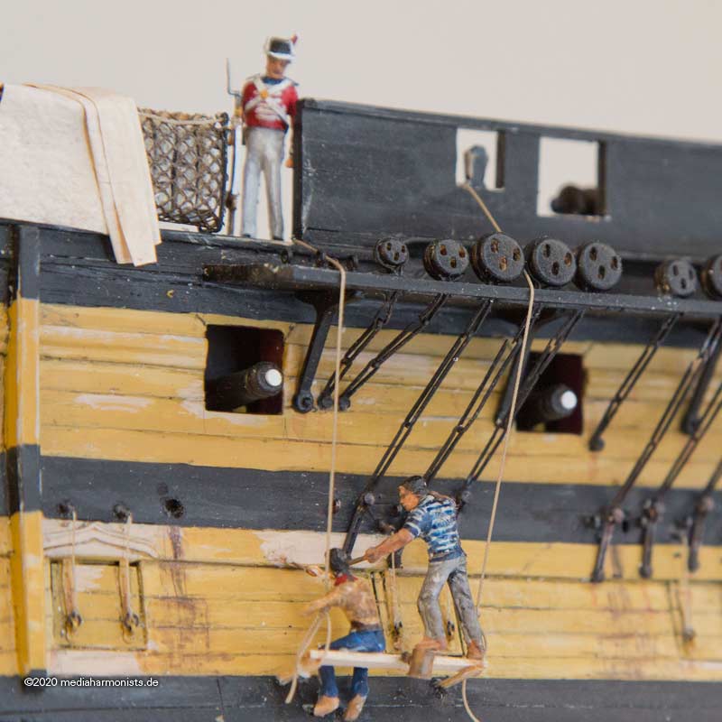
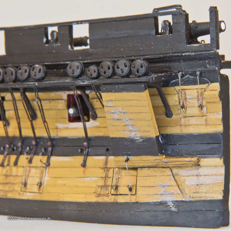
The most iconic appearance of the Victory is the one of Trafalgar. And this is also the most obscure one, as it lasted the shortest and was almost not documented.
Contemporary sources are very thin, as the great repair took place under pressure of time in the height of the raging war, and proper documentation did not take place or at least is not known. Quite sure is, that the channel boards were moved on top of the ports, and of course the stern was most possibly closed in.
Most actual details can be found in Turner´s sketches as he draw some scribbles after the ship came back. Nicely seen is the build barricade of the forecastle, other details like the anchor lining are more obscure and subject of interpretation and discussion. Also th be guessed are the thinner black stripes and the yellow gunport lids.
Biggest ongoing discussion is the color of the yellow. Today a light terra cotta, in contrast to the usual yellow buff as seen in contemporary paintings. The actual guess is that the yards were short on buff and stretch it with red and white witch was available. Any way my personal believe is that ships of that age - as we were before industrial RAL definitions - were much more a patchwork of different colors, just always the surprise which shade would come out of the barrel of paint. That is also the story I am telling here, the two sailors applying the shade of ochre that the ship is painted today 🙂
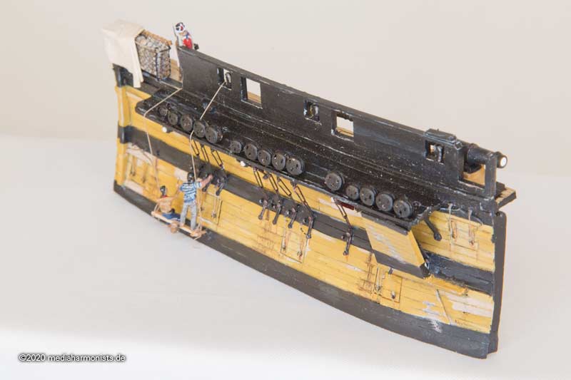
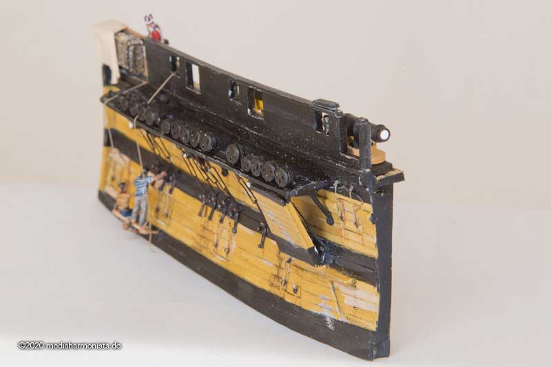
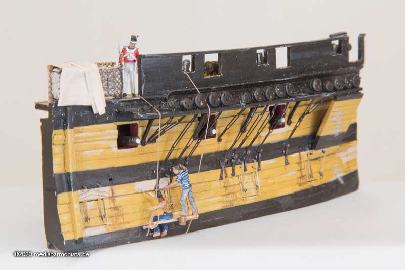
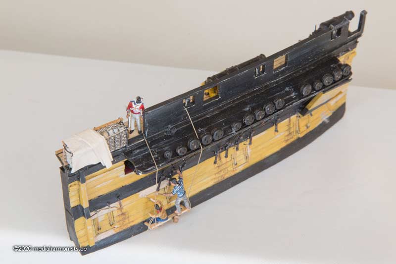
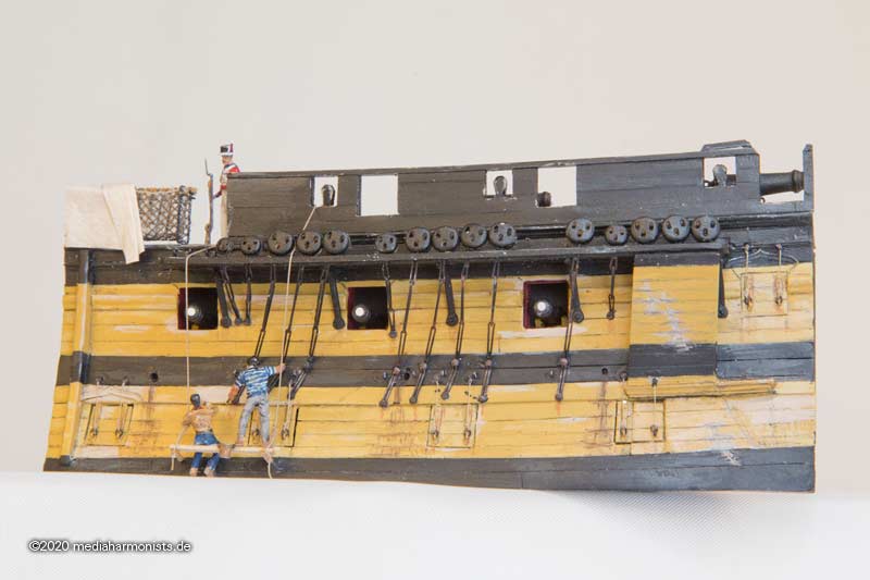
Our Royal Marine now wears the new uniform introduced from about 1800 onwards, with round head, no revers and no swallow tails. The other sailors wear still no uniform yet.
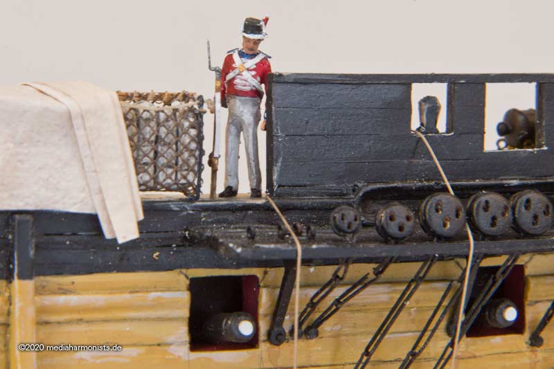
Difficult to see on Turners oeuvre is the anchor lining. But still a quite too useful installation to miss it out.
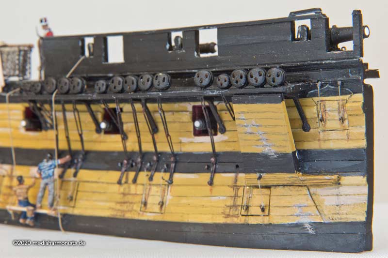
On the channel boards one can see the partner for the short fishing davit.
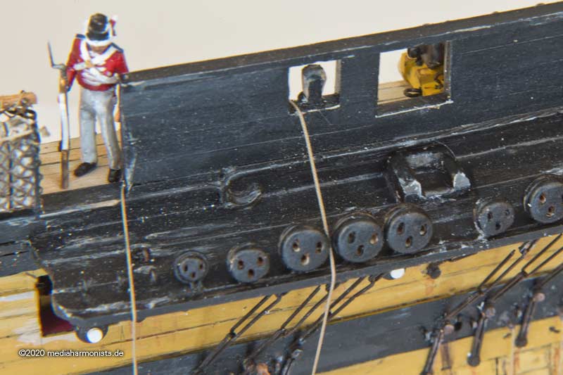
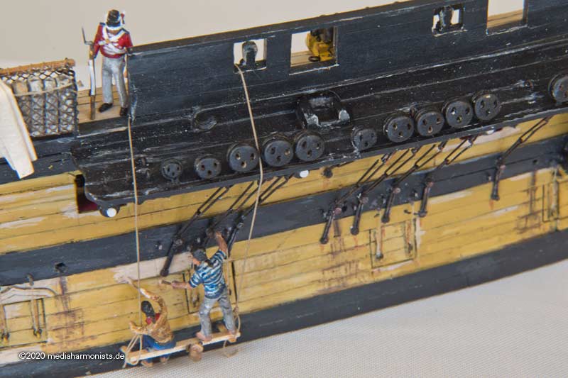
For the 68 pounder carronade - taken over in 1804 from the Kent - the railing on the barricade has a hinge to protect it from the muzzle flash and to facilitate handling.
And as mentioned already before, thanks to @Morgan for all his great hints and input!!!


Fighting ladders
in Discussion for a Ship's Deck Furniture, Guns, boats and other Fittings
Posted
Just bringing it up again. Did anybody have any new encounters with this topic in the meantime?
Cheers, Daniel