


dafi
-
Posts
2,434 -
Joined
-
Last visited
Content Type
Profiles
Forums
Gallery
Events
Everything posted by dafi
-
 Very tasty result! Never realised that you posted here, thank you, great work! All the best, Daniel
 -
Thank God, they were not gruel, oups, cruel or better saying authentic in this sense ;-) But some of the breads hat cabbage on it, for us not to fall ill with scurvy on this long day-trip. XXXDAn
-
And then the most important thing of the day: Food! Food! Glorious food! Then they sat in all the corners possible ... ... and enjoyed themselves quietly ... ... and after a bombastic fennel soup there were still plenty of hearty slices of bread coming ... ... everything freshly prepared on board :-) So we got the power to get some lessons in working the windlass, now we know how it works ... ... tough job but in the end the anchor was finally up. And then the most important: the desert :-) Some sweet slices of Victory, made and presented by confectioner dafi ... ... everyone was allowed to get a taste of it ... ... and was delighted upon the awarded piece! That was a dream getting true: Going to sail with my models :-) How many did have the chance to present their models in such a true surrounding!?! XXXDAn
-
Just realised, I never told you how I got the medal on the last picture of the Utrecht ...hihihihihihihihihi... Not too long ago I was visiting some friends on a modeling exhibition at Fürstenfeldbruck near Munich. I suddenly saw some people disappearing with some great models. I told the guards about the supposed theft and they calmed me down: "Going to the competition" they said. Wanted to see what this means I went there and I saw hundreds of tanks, bi- and triplanes, strip-downs and full-dressed and loads with evil crosses. And then I dicovered one single ship among all those competitors: a wonderfully build RJN Hiryu. Then I saw the medals for the categories, heard the price to take part: 2 (zwei, two, deux, due) Euro and only 1 competitor for the ship´s category? First cheap enough and the second to little competition for my taste ;-) So I ran to the car, got my slice of Victory out - By the deep 17 if one remembers - ran back and 2 (zwei, two, deux, due) minutes before the submission deadline I threw my model onto the table like James Bond his hat in direction Miss Moneypenny. Then some times later the big medal awards ceremony, can you guess what? I made a wonderful second (2, two, deux, due, zwei) Place!!! The other competitor in the category "Ship" only made it to before last. And the only one ahead of me was becoming "Best of Show"! What do we learn from that? - First, dafi never took his medal off again, everybody who saw me evermsince can confirm that! - Those 2 (zwei, two, deux, due, two) Euro were economically well invested - dafi is stupid, for another 2 (zwei, two, deux, due, two) Euro he would have gotten also the bronze medal as he had another slice of Victory still in the car. This is Frank who got a bronze medal with his biplane-strip-down against a competitor field of a felt 723 other planes. So I was better than he was as my beloved medal is SILVER. XXXDAn
-
Born out of a brain fart while joking around in the german forum, a crazy idea became reality and within 12 hours more than 12 people already wanted to take part in it. Soon later we had 20 pirates from all over Germany plus some admiralties in tow that went to the Ijsselmeer, or better to say the Markermeer in the Netherlands. In a well planned and immaculately executed attack we were successfully boarding the beautiful Staatenjacht Utrecht and we found ourselves in the mids of our wildest pirate dreams. And so the scum of several german forums gathered underneath the blood-red-yellow-lioned flag. Foolhardy pirates ... ... applecakesmutjes ... ... in short, the whole landlubbery motley crew was overwhelmed ... ... as the cake was marvelous and more important than the captains speech: "If we sink, do not panic, the water is only approx. 2 meters deep, so be prepared to only get wet feet." But one could see his thoughts: "Oh my god, what have I done to deserve this?!?" Finally on the endless sees of this lake: Putting up sails, everybody had to help ... ... what a delight for a pirate´s soul ... ... then the staysail ... ... and to put up the jib one had even to climb outboard defying deaths and horrors. Look at these professionals at work. The master gave the directions how to coil the ropes ... ... but as usual it ended up in some kind of private bondage lessons. The leeboards had to be put down and up depending on the tack ... ... even the the tiller we were allowed to touch and steer ... ... and - big management mistake - even me they dared to try to cope with steering, so of course the company went a bit off course ... ... but just look, isn´t my silver medal glowing beautifully under this tropical sun ?!? XXXDAn
-
This one I found two weeks ago on the foot of the 7 Provinciens at the Batavia Warft in the Netherlands. Was this an omen that the build was meant to be put on ice?!? XXXDAn
-
Ok, no cat got harmed . I think every scale needs its own technic, as the challenges change. For scale 1:48 thin cloth can work out fine, from smaller than 1:150 paper gets a wonderful choice. My scale of 1:100 is somewhere in-between: The cloth is too coarse or too transparent, on the other hand the sails are too big for paper, also I would like to add some details, that would be difficult in paper alone. In real life I did not have to much time to tinker around due to job and privet commitments, but some small experimenting I could afford. I prepared a small extract of a stay sail, using my laminate technic. I reinforced the leeches by 0,3 mm copper wire The material is that thin, one can see the copper shining through. Took a wet cotton stick and resoftened the sail partially to slowly form a soft wave. The anvil were the handles of a scissors and the hammer was the hot iron. And here the fascinating thing, how the appearance changes with the different moods of light ... ... as originally intended :-) OK, one could guess what comes next ?!? Almost. Another reason for testing to see the limits of the material. And what should I say?!? If one uses hard and pointed tools to make smaller crisps into the material and one slips, the material breaks! But also one can see the benevolence of the material ... ... cleaned and a new leech glued on - this time no copper inside - and it looks like new! And to prove that this invention is really mine, I left a good part of genetic material in the superglue to provide enough DNA-Tests for the future :-) Then formed the hanks for the stay ... ... and tried to fix them, still without leech rope, but still it was quite stable. First trials on the right were not so really shipshape, useful was the third hand of table, clamp and clamping tweezers. And slowly ... ... I was happy. Even though the fixture of the hanks is on the really outer edge, it proves to be very stable. So tried the technic on my small sample and heaved it up. Even though it looks soft, it is quite rigid and keeps well the form due to the white glue used to stiffen it up. Then resoftened with a wet cotton stick partially to get the wave stronger (remember - went bad already once ...) But this time it worked out fine :-) So slept over night - or perhaps not that good as one of the 17 beers that night must have been bad ... ... felt a bit crunched and wrinkled and had the feeling, the sail should exactly represent that. ... fits ... ... XXXDAn
-
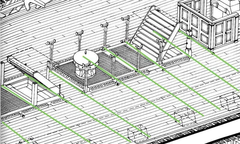
Very nicely done the curved planks! Marking the positions of the butts is the best way to do, but be aware, the frames of the kits are usually not in the right positions! You can see on the sketch, that the beams - and therefore the butts - go through the scuttles. Like this the cargo would go not downwards. The position of the beams are always in front and back of the scuttles, or better saying in real life the scuttles follow the beams underneath. [/img] XXXDAn
-
Not too much time to tinker lately due to my working scheme and other private commitments. In the meantime I was already looking for my cat for quite a while. And how do you know, that you found the new daytime hideout of this feline creature? Next modeller´s meeting there will be a lot of chilly con cat ;-) XXXDAn
-
Thank you all for the nice comments. @Richard. Looks like you did not manage to go through the whole report yet ;-) Still further down the page there is more about the copper ... #22 ... and down the road you will find more here ... #53 ... and the most important update here: #1113 ... and some more adventures there: #1203 Actually the Copper is laid over the original Heller structure which surprisingly gets the pattern quite well. Only flaw is the exaggerated height of the overlap. Seen the original thickness and compared to the scale, actually no step should be visible. Even pictures from coppered ship´s bottoms do not reveal the step, only real close ups do show. Next life I will sand the plastic imitations down and will tile the copper flat, the overlap just indicated by a hint of nails. Also there are much more shades of color on weathered copper, telling the story what the ship did last and where it has been, see here: #35 Cheers Daniel
-
The one with the plank on the bottom is the older version as far as I know. I do not know when the switch models was done, neither how long the older one was still in use. Perhaps contact Mr Delacroix. XXXDAn
-
Be cautious with the drawings of the planking at McKay´s and McGowan´s books! Both of them show just simplified "mock-"planking, not respecting the beams underneath. One can see butts on the level of then middle of coamings or companion ways. That is NOT correct, those ends would hang in mid air. I marked all possible positions for butts with green lines. All butts in between are incorrect. Only on the green lines there are beams underneath to nail onto. Also note the different distances of the beams, leading to different lengths of the planks. And with the correct spacing of the beams underneath the planks become much longer than shown in this picture. XXXDAn
-
*jumping of joy* Thank you MAurice, it was a great trip to revisit this wonderful build! XXXDAn
- 366 replies
-
- 3
-

-
- pegasus
- victory models
- (and 2 more)
-
What lines? XXXDAn
-
Much longer than the 6 meter Mondfeld states :-) As the butts need to respect the deck beams underneath - see their position in AOTS - and with a 3 butt-shift system one gets over 12 meter long planks in the middle of the deck! Also as the deck beams do NOT have the same distances, the length of the planks varies quit a bit! See here the lower deck of my Vic. #68 And if you wnt to be brave, do NOT use straight parallel planks as I did, use the curved ones as this is most possibly more contemporary. XXXDAn
-
Nive build. Love the test-scan for the etch, great for early test-fitting! For the vacuum staircases and other black holes - also gunports - I also use some cotton. Just get a very fluffy quantity into the opening and also dust stays out :-) XXXDAn
- 295 replies
-
- 1
-
-
- victory
- caldercraft
- (and 1 more)
-
Worked, thank you!!! XXXDAn
-
Thank you, but sorry, still no luck ... ERROR: There is no document with the provided identification number. XXXDAn
-
Thank you for the documents! Unfortunately it looks like the link is wrong: Source: McHenry, James. 1797. “Uniformity of Dress on Ships of War.” http://wardepartment...nt.php?id=22778 It redirects onto this page ... XXXDAn
-
New and need help to identify a mystery model? Read here first!
dafi replied to ccoyle's topic in New member Introductions
But sometimes one get´s a real gem. Here is incredible Willi Meischl on the restoration of a "dustpan"-finding, narrowly escaping it´s fate. It proved to be a historical model of a Austrian trading brig from the 1870ies. See the video of the restoration. Excuse the quality, it is from a VHS from 1988-1989 and we were lucky to still be able to transfer it :-) So better check twice :-) XXXDAn Allow some off topic: Also enjoy Willi´s build of the model of the arctic explorer vessel "Admiral Tegetthoff", displayed in the technical museum in Vienna. https://de.wikipedia.org/wiki/Admiral_Tegetthoff_(Schiff) There is also a nice film from the ORF (official Austrian TV) that shows him building a 1:1 Model for a film of the expedition. Unfortunately not on Youtube as for Copyrights :-( XXXDAn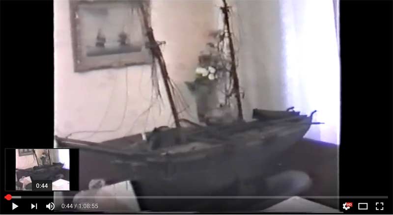
-
To put the rule to the test, or - in other words - here comes the big rag, part 1. To get the overlap right this time I constructed a small light table: 2 logs, some glas and a lamp. Above light from underneath, below light from the top. To get things straight I printed the pattern onto a paper and glued it face down onto the glas with a minimum spray glue. As I also sprayed the back of the paper, the silk is nicely fixed and does not move while working. Do not face the print towards the silk, or the heat will transfer the laser toner onto the tissue - unless it is wanted :-) The silk I used for the gaff was is pongée 8 as this sail was a more heavy cloth. Constructed a small cutting machine for the panels ... ... and started bravely ironing. First side went rather fast, then flipped over, adjusted to the grid and restarted and went immediately tilted ... ... but was no problem to scratch that off :-) Here the result in changing ambient light conditions, just what I wanted to see, every time it looks different :-) The overlap is still to broad, that was a mistake of mine. To make the overlap more visible, I still added a 1 mm stripe atop, see the spaghetti in the back of the picture. It was surprisingly easy to do and exact in the outcome. Then the slightly curved reef bands and the other doublings ... ... and step one was done. The size of the sail can be seen as soon as my little ship yard worker is added. And just for fun: The original out of the box :-) :-) :-) So next steps will be great fun: Adding the bolt ropes and the glue-paint mixture and waiting if everything stays as crisp as it is now! XXXDAn
-
Hello Andi :-) The last engraving with Victory showing the old fashioned entry port - as depicted in Slade´s drafts - is 1779 Victory, „Sailing by the White Cliffs of Dover“. In 1780 she had a refit also and was coppered for the first time - and since that day the port vanished from all sources until it reappeared in 1828 after another repair. But by then, the port was one more opening further in the back. Since then it was to be seen in all sources until it was moved to todays position in the 1920/30ies. The disappearing side entry port is nothing specific to the Vic, it started to disappear from all first and second rates around 1760, the time of the Seven Years' War and the War of Independence - high times on the seas and plenty of trouble with the french. A coincidence? The ports just started to reappear around 1803/1805. XXXDAn
-
First the most important question: What ship/era/nationality are we talking about :-) It is he most common during the later times - as druxey and others point out - that the sides are vertical and bottom and top follow the line of the deck. This allows the frames - which were build vertically - not to be weakened by cut outs and also gives the same height level towards the deck and also allows the spriketting to pass uncut underneath the ports. This applies for carvel build with frame first and vertical frames. Now the "it depends": Older ships build hull first - like Vasa or contemporary dutch builds - where the frames were afterwards applied into the hull and were not vertical, pointing towards the ship´s middle on the top, thus resulting in tilted squared ports like #D. XXXDAn
-
Perhaps Nelson and Hardy wanted to match the copper´s color on the ships side as it is suggested by the latest research *duckandcover* XXXDAn