


dafi
-
Posts
2,434 -
Joined
-
Last visited
Content Type
Profiles
Forums
Gallery
Events
Everything posted by dafi
-
Quarter galleries: "they also afforded those officers a view of the forward sails of the ship without having to go outside" That is another statement that I would like to have contemporary evidence for. Seen that the windows glass in the wrecks are rather not clear and also the angle of viewing is not the best, the main sail hiding most of the other rigging, I have my strong doubts about that fact. Reminds me on the red color to hide the blood. Also seen that french vessels usually had mostly fake windows in the Galleries, I sometime doubt that english ships had that much glass in the back as seen on the models that had to impress the nobles for budget reasons. But that goes beyond the original marines walk ... XXXDAn
-
 And do not forget, ships went through a lot of changes throughout their career :-) So sometimes there is more than one possibility. But the original draughts are always a good "inspiration". XXXDAn
 -
A companionway/ladderway always needs a bigger opening with larger distance in between the deck beams to pass ladders, sailors or even goods. A skylight can be only a part of the deck not being planked and showing the deckbeams underneath running through the opening. See for example HMS Victory for that detail. http://www.mediaharmonists.de/bilder/Sammler29/Victory-161113_2569.jpg XXXDAn
-
Rigging lines located inside of shrouds?
dafi replied to Mickgee's topic in Masting, rigging and sails
Finished yes, but only as a slice :-) But there are actually 7 or 8 lines behind the shrouds, and as mentioned above these are different halyards, sheets, bunt lines, clue lines and tricing lines placed according to McKay´s rigging plan of the foremast in AOTS of HMS Victory. Also all thicknesses are conform. The shroud trucks that are empty are the ones for ropes of the stun´sails, which are taken down if these sails are not set. XXXDAn -
Rigging lines located inside of shrouds?
dafi replied to Mickgee's topic in Masting, rigging and sails
Here is an excerpt from my Victory: And then came a nice summer bouquet of assorted halyards, sheets, bunt lines, clue lines and tricing lines in a rich assortment of thicknesses. Some clamps still free for the stun´sail´s rigging XXXDAn -
I do recall that in "Voices of Trafalgar" one vessel reports that some ladders were thrown overboard prior the battle, perhaps Royal Sovereign. XXXDAn
-
Just discovered: wonderful build! Not because you used etch, but because you are doing a great job! Cheers, Daniel
-
Another guess are the "fighting ladders" that I am still researching for and that should replace the larger wooden ones in case of readying for action. XXXDAn
-
Finally finished the step. Small tip in between: If all sides are stabilised with CA, one can cut 0,25 slices with the resin saw from a wooden 4 mm batten :-) What that for? For the sheaves in the mast :-) And that brings us back on the track. Foretop and fore topmast done. And here compared with the "original" Especially the wrong angle is corrected :-) And the new detailing. The cheat in the heel is corrected, sheaves and a decent lock are fitted and the cap is made smaller, as it was the same size as the main cap. XXXDAn
-
After doing the maintop, just wanted to smarten up the foretop to make some castings, as I still need several of them for some tests ;-) Then realised that my standards improved since the top was first done. So when trying to dissemble the top it proved not a useful base any more, so a fresh construction was a must - at least for me. Perhaps one remembers earlier posts. The top Heller supplies is quite ok, just an old version, that was only used until 1802 (and displayed on all models I know since the 1920ies). An admiral order from 1802 states to fit a top of two halves on big ships, as they are easier to replace. As the Vic was rigged in 1803 and could be considered as a big ship, so I dared fitting one, better saying two halves ;-) Based on Lees and other sources, there should be sleepers on the top of the top with half the thickness of the crosstrees, reinforcements on the rim and a different scheme for the battens. So got the Heller top naked, reinscribed the planking and fitted the missing bits and made new and slimmer holes for the irons. To cut the crosstrees and the sleepers, I used a vice and with a single cut it was done. And then a small orgy with Evergreen and the new top was done and a bit more crisp than the old version :-) Anyway, Heller keeps surprises me, as on the "original" top the complicated planking scheme, with up- and downside looking different, was faithfully done :-) XXXDAn
-
Hello Thomas most of the figures date from mid 2015, see here for an example Film Crew @Jason, for the rest, nothing is decided yet :-) And Dave, no need to be sorry, that is one of the companion ways, situated in the middle. XXXDAn
-
Something I always wanted to tell: A small portion of the upper deck laid, and one sees much better how claustrophobic the situation was ... Ashes to ashes, earth to earth and top to tops ... ... business as usual. XXXDAn
-
Anyway, they are not too bad as they still had different proportions than the guns in later years. The pictures of the original guns recovered show a much slimmer barrel than the ones on the Vic. https://www.ouest-france.fr/pays-de-la-loire/la-baule-44500/le-canon-du-soleil-royal-sinstalle-passage-de-la-ladure-1190342 https://www.google.de/imgres?imgurl=http%3A%2F%2Fi34.servimg.com%2Fu%2Ff34%2F15%2F24%2F95%2F84%2Fcanond11.jpg&imgrefurl=http%3A%2F%2Fmodelisme-naval-bois.lebonforum.com%2Ft138p50-soleil-royal-1669-au-1-72&docid=ObKeddvYMMpN1M&tbnid=qJdCqDfY3UwBqM%3A&vet=10ahUKEwjy_InlrdrWAhUiDJoKHTb-D0UQMwg3KBIwEg..i&w=800&h=531&bih=789&biw=1440&q=soleil royal cannon&ved=0ahUKEwjy_InlrdrWAhUiDJoKHTb-D0UQMwg3KBIwEg&iact=mrc&uact=8 XXXDAn
-
Hy Marc, the barrels from Victory are the original ones from the kit, just some etch added. The Heller kit often surprises me, as many parts are quite close to the original. Most actions necessary come from the limitations in making the moulds some 40 to 50 years ago. Here is a link to the instructions of the etch parts that deal with the guns: http://www.dafinismus.de/bilder/Platinen_ab_2015/Etch_Victory_en_5_V12.pdf http://www.dafinismus.de/bilder/Platinen_ab_2015/Etch_Victory_en_4_V12.pdf http://www.dafinismus.de/bilder/Platinen_ab_2015/Etch_Victory_en_7_V12.pdf But even the Soleil guns look much better if some simple modifications are done: replace the trunnions and the axels and bore the hole for the breech into the carriages´sides. In the back the original, in the front the pimped version. ]
-
You got it Jason :-) But not only while being hoisted, also once the topmast is in place, there is nothing else that helps counteracting the weight, as the topmast is not linked/fixed to the main cap. XXXDAn
-
Bolsters for the yard sling in the back and 2 for the lift blocks in the front :-) XXXDan
-
Thank you folks! Some more remarks/questions: - Lee writes on page 56, that the top mast pendants were unrove after the mast was topped. Does this mean that before that date the topmast pendants stayed in place? - Lee writes and contemporary drawings show that the port side pendant went through the lower sheave. - According to Lee large ships - like Vic - had tripple blocks lashed to the pendants instead of the usual double blocks. - In the pictures is shown a top made of two halves as by Admiralty order from 1802. (Just a splitline in the middle missing as I saw in my pictures). That is why there is not the usual axial pattern of the rips, but a version according to Lee, Nares and Brady. - the octogonal heel does not necessitate a groove for the pendant as there is enough space to move freely. - the bolsters of the lift blocks on the cap need to be pushed more forward, as they need to be wrapped around the cap and collide with the mast head in this setup. - still to be confirmed the octogonal heeling and the jeer clamps. XXXDan
-
And some end-of bank-holiday-tinkering: blocks mounted, topmast pendants set and the main cap´s round hole padded with leather - what does a modeler´s heart need more?!? XXXDAn
-
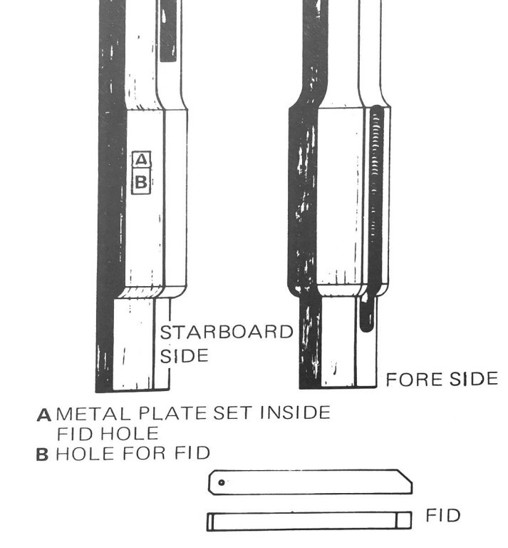
Some questions about the masts of British first rates about 1800. - Usually the heel of the topmasts is shown squared, the heeling on the Vic in P. is octagonal, as it is shown in Lee, who states that "Octagonal heeling only on 1St rate ships and by 1773 on all rates" http://files.homepagemodules.de/b564537/f700t5845p131075n2_FzsqAJVt.jpg[/img] Are there any contemporary sources confirming that? And another question arose: The cleat for the jeer block lashing are shown in Portsmouth as a clamp, but most of the literature shows a shoulder piece. What is the correct setup? Was the cleat an earlier or later version? Here both of them together for comparison ... ... and here the shoulder its the right place.
-
- 1
-

-
Univers played crazy - it concentrated lust, leisure and time in one single small space and as this happened to be my tinkering corner there was no more way to say no ... I was busy for quite a while understanding the real construction of the fighting tops and researching the relating measures in between mast and topmast and so on. Found the Heller parts in acceptable tolerances so made up a plastic dummy to set things straight for a wooden replacement later on. A long missing piece for the puzzle was the small wooden chock, that sets the distance on the lower end of the topmast and defines the distance from the mast head to the topmast. Difficult to spot in the plans, not easy to spot it in the descriptions as it was too easy as a solution ... So I shortened the rubbing paunch to fit in the chock, shortened the bolsters in the front side, detailed the main cap ... ... build in the sheaves, the fid and the iron loop ... ... and also worked the top. Nice to see the chock that sets the distance and the rake of the topmast. The main cap got its splitlines. Another question arose: The cleat for the jeer block lashing are shown in Portsmouth as a clamp, but most of the literature shows a shoulder piece. What is the correct setup? Here both of them together for comparison ... ... and here the shoulder its the right place. Then made he functional tryouts ... ... pushing the topmast through the trestletrees ... ... placed the fid ... ... and fits :-) XXXDAn
-
Best material for small scales :-) Posted February 20, 2013 XXXDAn
-
Statenjacht Utrecht by Angarfather - 1:36
dafi replied to Angarfather's topic in - Build logs for subjects built 1501 - 1750
Wonderfully done! And this is how one works the leeboards - from our forum´s trip to the Netherlands :-) XXXDAn -
I HAVE A COPY OF THE IMAI INSTRUCTIONS FOR 1/100 VICTORY
dafi replied to Bishophobbies's topic in Plastic model kits
Big thank you Paul! Many modelers already asked for them having illegible Heller copies and/or not being able to interpret them. XXXDAn -
As I am "building a piece of plastic" too, I never had that impression. Even more so, my "piece of plastic***" is the fourth most viewed build log on the board, only being surpassed by Dan´s Vulture, Ed´s Young American and B.E.´s Pegasus, what an honor! But one has to have a bit of patience and keep on waving the flag, I unfortunately never realised this build being shown here. Same happens to me, sometimes little or no response, but this happens too if one builds scratch and in wood I believe :-) I even would wish for more pictures! All the best, Daniel *** that is how my wife calls it ...
