


dafi
-
Posts
2,284 -
Joined
-
Last visited
Content Type
Profiles
Forums
Gallery
Events
Posts posted by dafi
-
-
Good one and wonderful! In our german site the question about the "vent trunks" came up too. Those are shown in the Vic today and are also displayed in the AOTS by McKay and this where the name was taken from. That´s why me too I incorporated them in my build, long before going to deeper resaerch and questioning sources like the modern authorities 🙂
My believe is that the principal source of the video is AOTS as other small bits fit in there too.
All the best and enjoy the show, DAniel
-
-
And now on to new adventures. After I was once again amazed by the print results of the iron swivel gun, I wanted to try out something I had been thinking about for a while.
One of the most time-consuming parts of the gun deck is the gun rigging, especially the side tackles. And you don't see much of it. Why not try something new there? A quick test shot ...
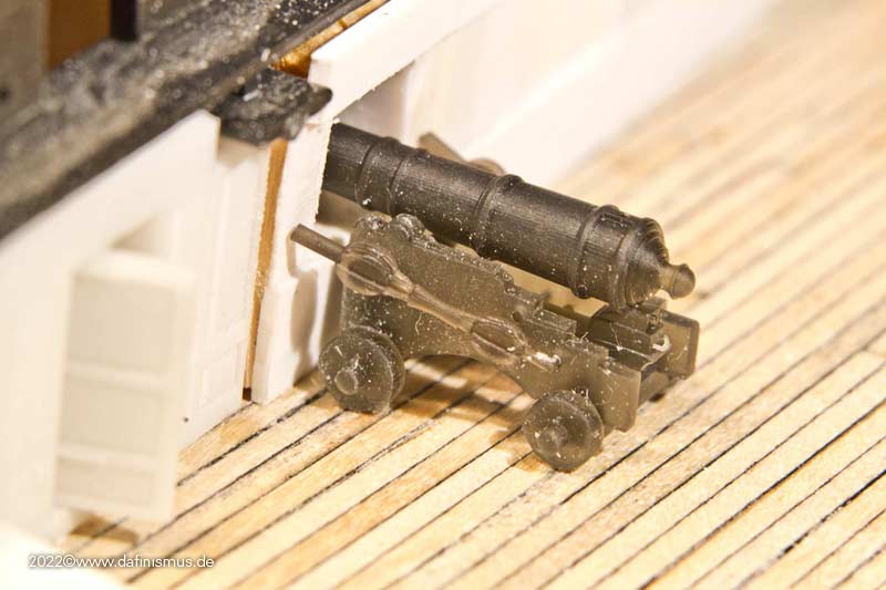
... which showed that in principle it fits http://www.shipmodels.info/mws_forum/images/smilies/icon_smile.gif
So I made it a bit more precise and quickly installed it.
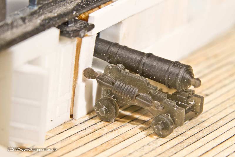
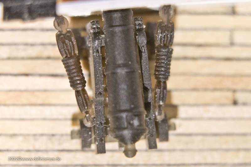
Still a bit much spiral spring, but I think something is possible.
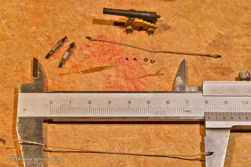
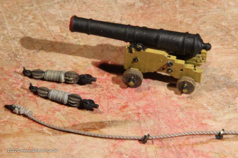
As a next step I made the ropes of the rigging a bit thinner, 0.3 mm instead of 0.4 mm diameter. I also broke up the uniformity a bit and added minimal variances. Old on the right, new on the left.
Then I swung the brush, added shading to each colour as usual, and added some ink to the whole thing.
This was the time for a little setting test. The inner planks were marked with a pencil, the knees were glued on and I noticed that the holes for the bolts were still missing...
... so I got out the shish kebab skewers with the incorporated drills and ...
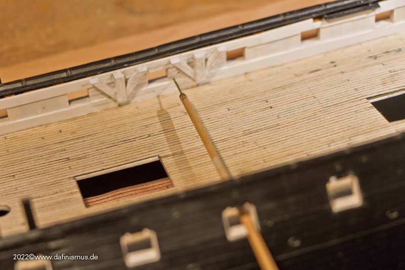
... drilled all the way through the ship http://www.shipmodels.info/mws_forum/images/smilies/icon_smile.gif
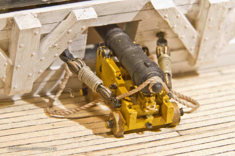
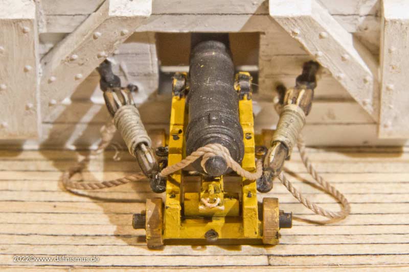
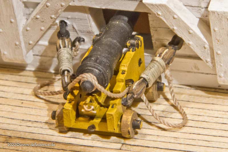
Attached the side rigging to the gun and tested the position.
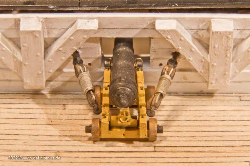
Fits, only the breech rope is missing.
The length is determined, all fittings are attached and ...
... wrapped the rope around the grape as in the Constitution.
Since the breech rope is longer than the rest, this could be glued in place without any finger knotting ...
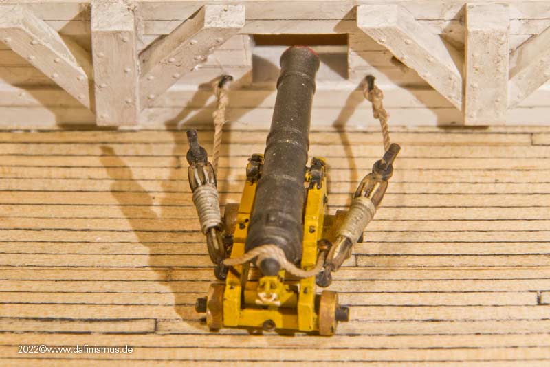
... and then the gun is pushed towards the ship's side, the guide rails are guided into the glued holes and the gun is placed, a little glue with the toothpick under the wheels and done http://www.shipmodels.info/mws_forum/images/smilies/icon_smile.gif
XXXDAn -
-
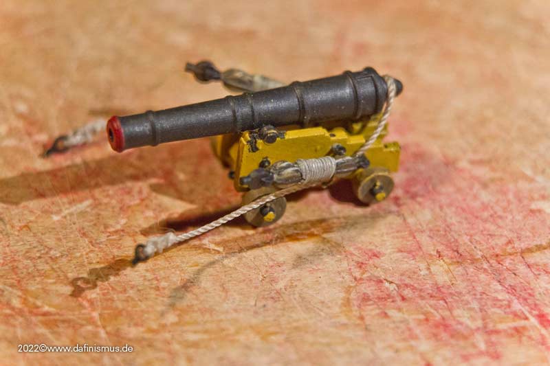
A short excursus.
The printer has once again spit out something, a small collaborative work from www.segelschiffsmodellbau.com
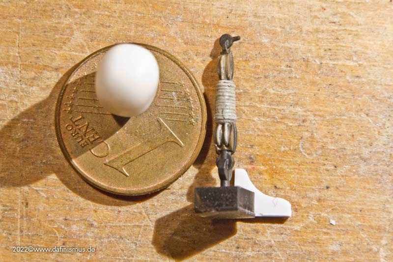
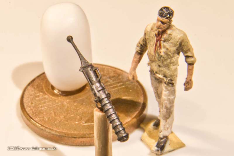
A small iron swivel for older ships.
Faramir had built the original file of the barrel, with me making a few more adations.
Interesting are the dimensions of the trunnions with 0.3 mm and the matching eyebolt of the holder. This actually results in a fully movable gun even in this scale :-)
All modern drawings known to me show the powder chamber handle always pointing upwards. After the first test prints I saw a Life-Fire video and realised that the handle was turned to the side and so the fuse hole was on top, otherwise the fuse would not have been able to reach it. So I turned the handle and inserted the fuse hole.
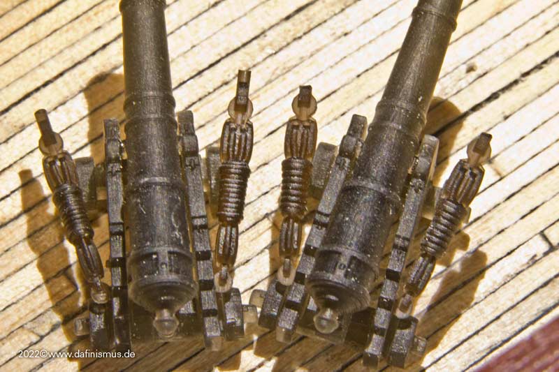
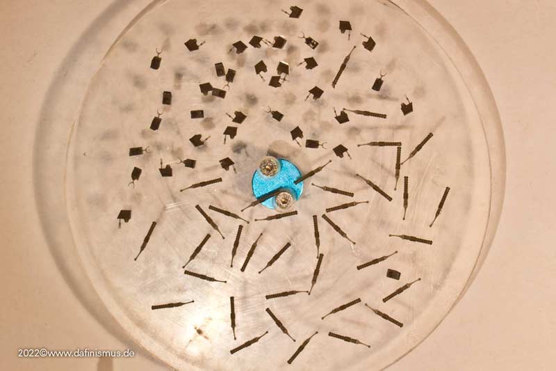
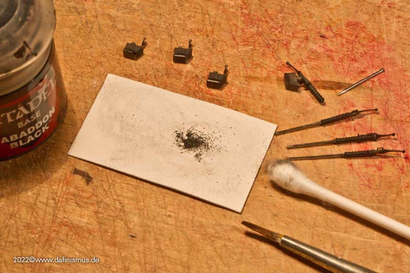
And there they were, the new prints. For painting, I put the barrels on a needle and noticed that the difference in diameter is not very big. With a very dry brush I brushed them with black paint, which doesn't put to much volume on and rubbed them carefully with graphite on a Q-tip.
I was most surprised that the firing hole is actually visible :-)
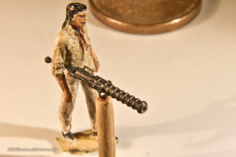
And because it is so beautiful, different views.
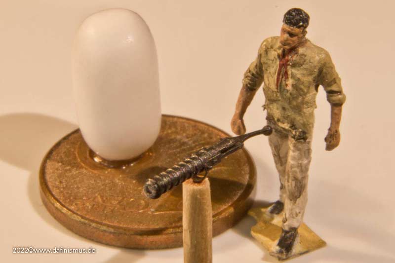
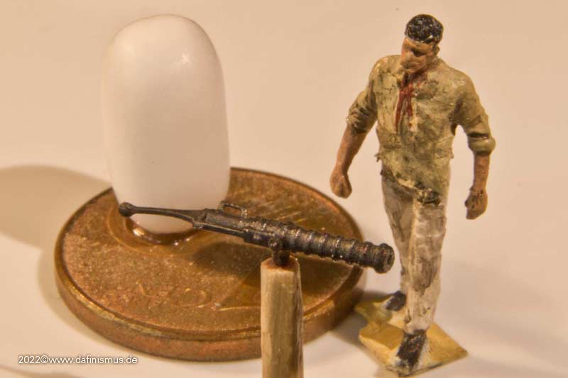
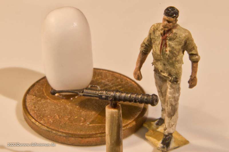
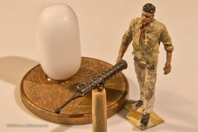
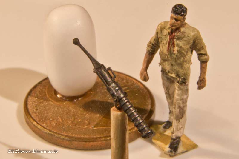
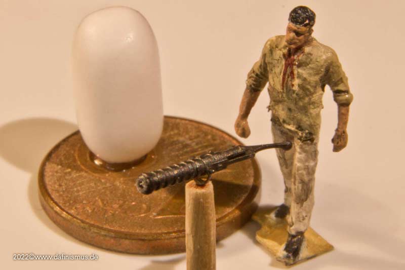
There you go, the bad boys may finally come 🙂
XXXDAn
-
Short interlude, "What if."
I wonder what the Constitution would look like with a 12 cylinder sports engine?
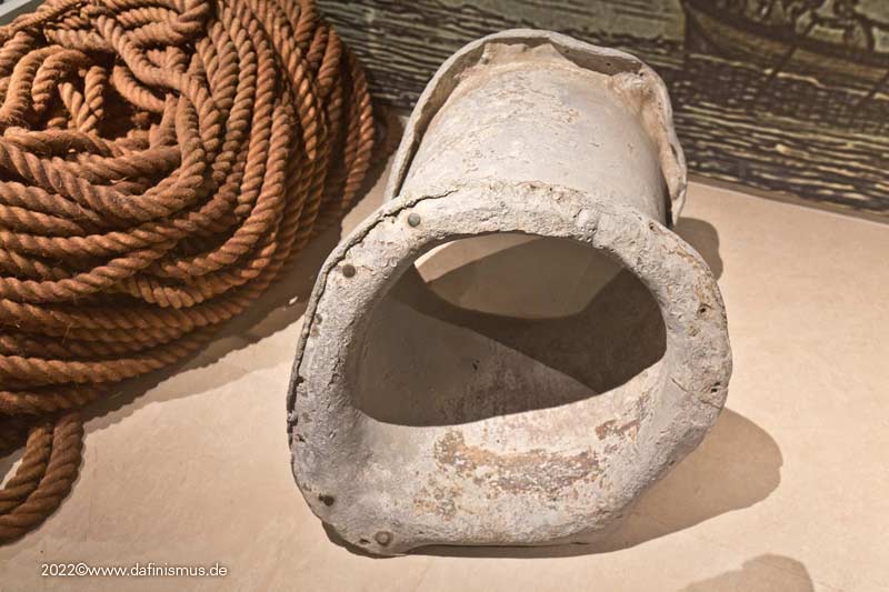
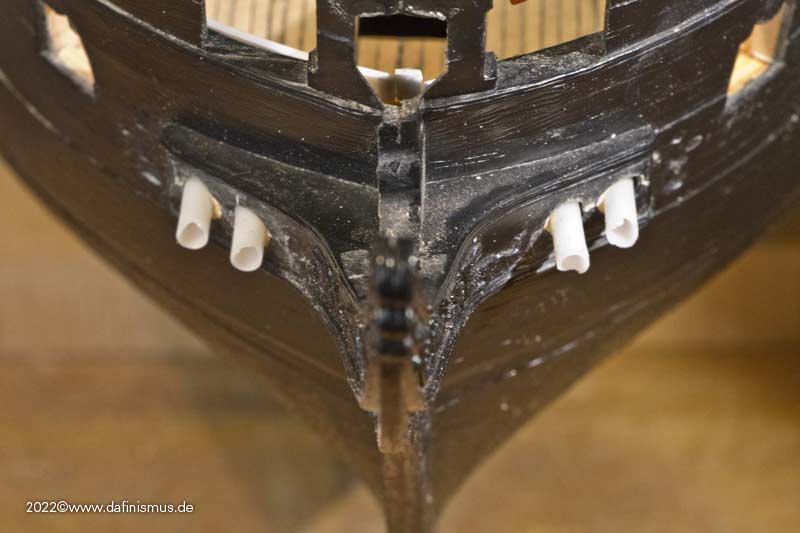
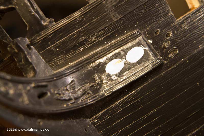
A contemporaneous anchor nozzle from HMS Royal George at Thorsminde actually still survives. A lead pipe with the ends flanged around.
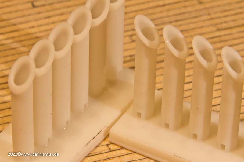
So new hawse inlays printed, with 3 mm inside, 4 outside and the curves at the flang.
Hawse holes drilled out to the nea diameter, inlets pushed in ...
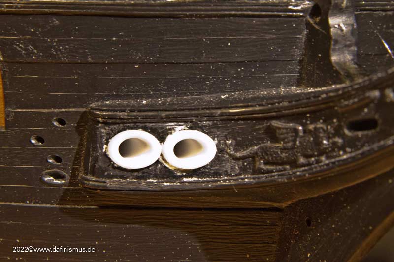
... and inside still another fake flange put on.
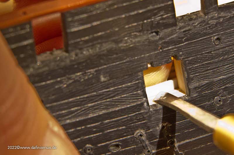
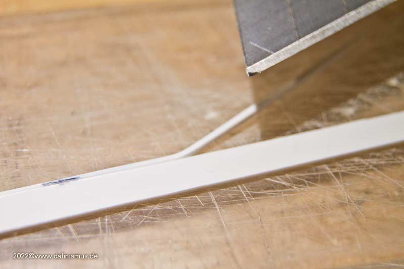
Now the whole area is also neatly wallpapered in one piece, the closed port is no longer visible, and the intersection of the plastic strips is in the middle of the port and will be covered by the gun.
XXXDAn- druxey, Prowler901, mort stoll and 3 others
-
 6
6
-
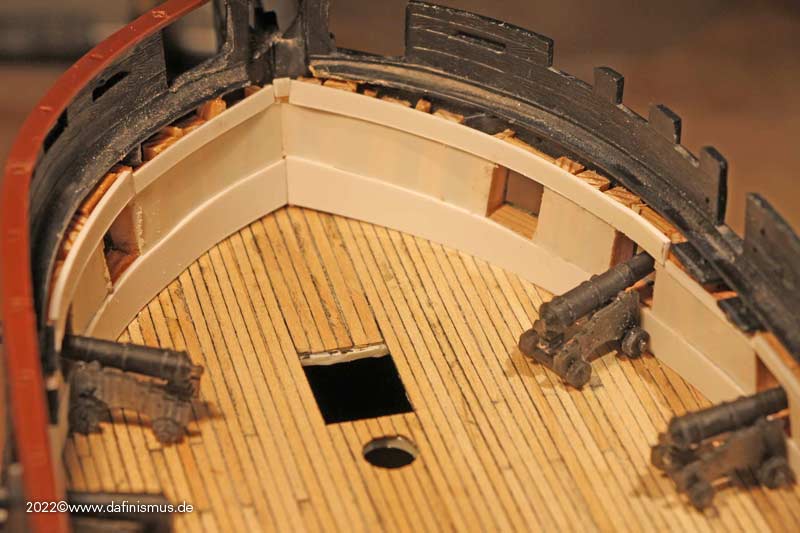
After that, I took care of the anchor hawses. In the kit, these go 90° perpendicular to the ship's axis and out downward.
Considering that the ship is driven away from the anchor by the wind on the tensioned anchor cable, there would have been a nice bend in the tensioned cable.
That's why the anchor nozzle has to sit parallel to the ship's axis with minimal downward slope. A toilet paper roll happened to be the right height and served as a rest for the Dremel.
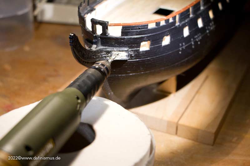
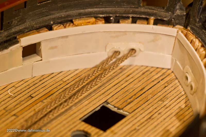
The anchor cable has about 2 mm in my scale, so printed short semi-finished tubes with 2.2 mm inside and 3 mm outside and glued them in and then still trimmed all after that.
Then the cable was threaded ...
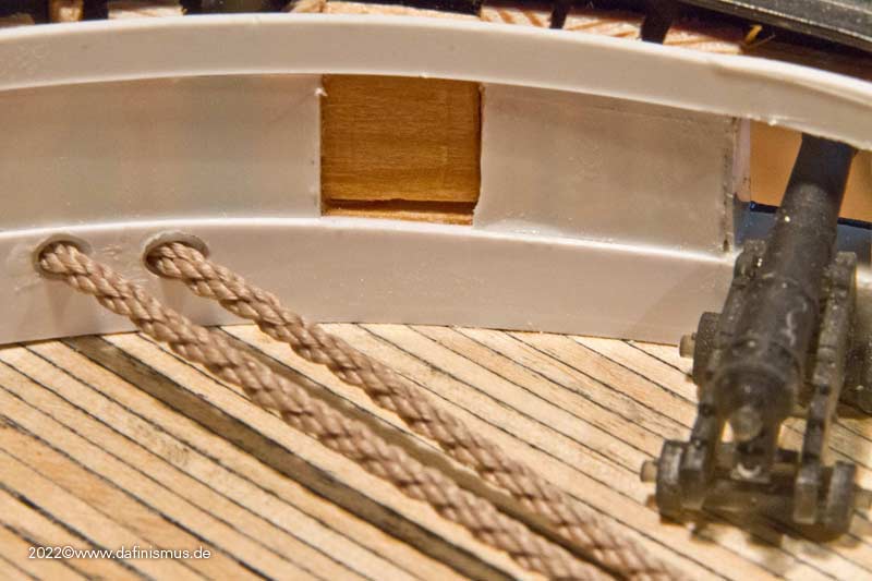
... and noticed, omg, there is missing the clearance. Often the anchor cables were still secured with various wrappings against chafing.
In addition, I decided that the ship is represented before 1812, and there the bridle port, the foremost port was not cut in yet. This one was not equipped anyway and served to facilitate the anchor handling. So this port was closed and I noticed that this would probably result in a nasty patchwork on the internal planking.
So came what had to come, a dafi did what a dafi has to do: Demolition!
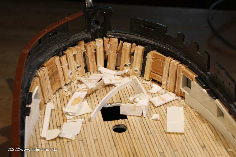
With these cruel pictures I just want to leave you ...
XXXDAn -
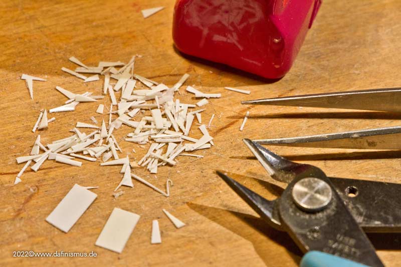
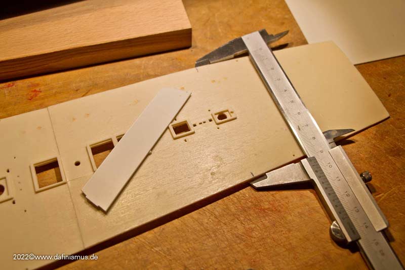
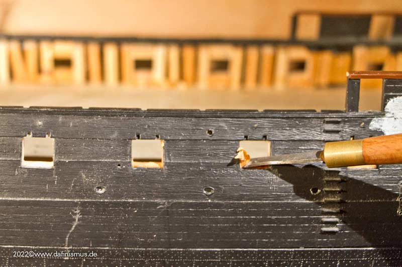
So far I had ever avoided, and the gun ports not yet clad inside. Was made up, so that one does not see the wooden slats and also file irregularities are concealed.
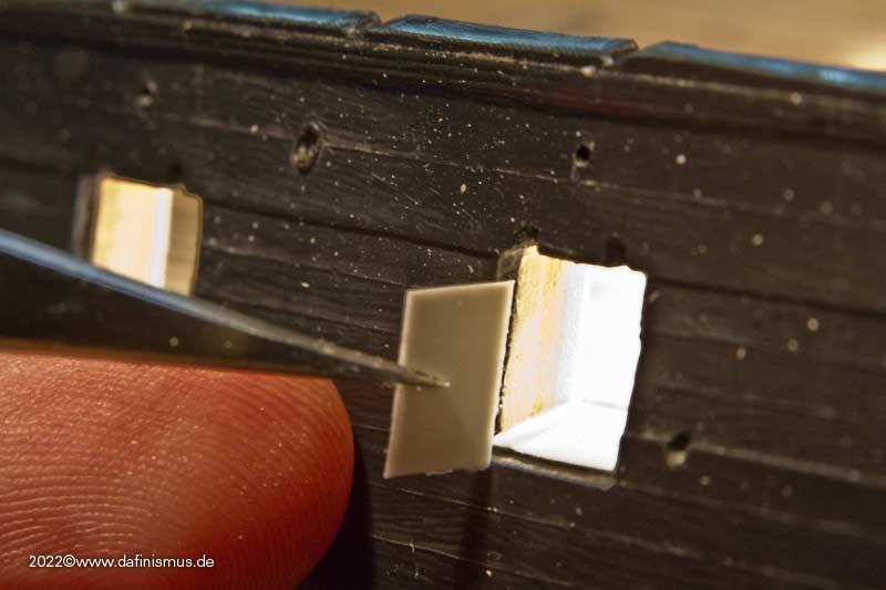
First all 4 sides laminated with 0.25 polysterol ...
... then trimmed the inside with a scalpel ...
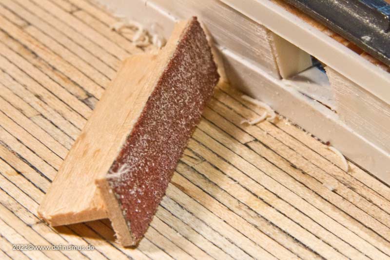
... built a small sanding block with a handle ...
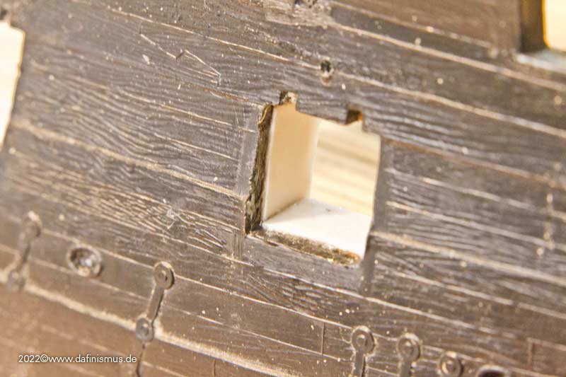
... and neatened everything.
Fortunately only 30 times and not 100 like the Vic.
Saved the scraps, you can still fill up any gaps with them.
XXXDAn- Prowler901, druxey, mtaylor and 2 others
-
5
-
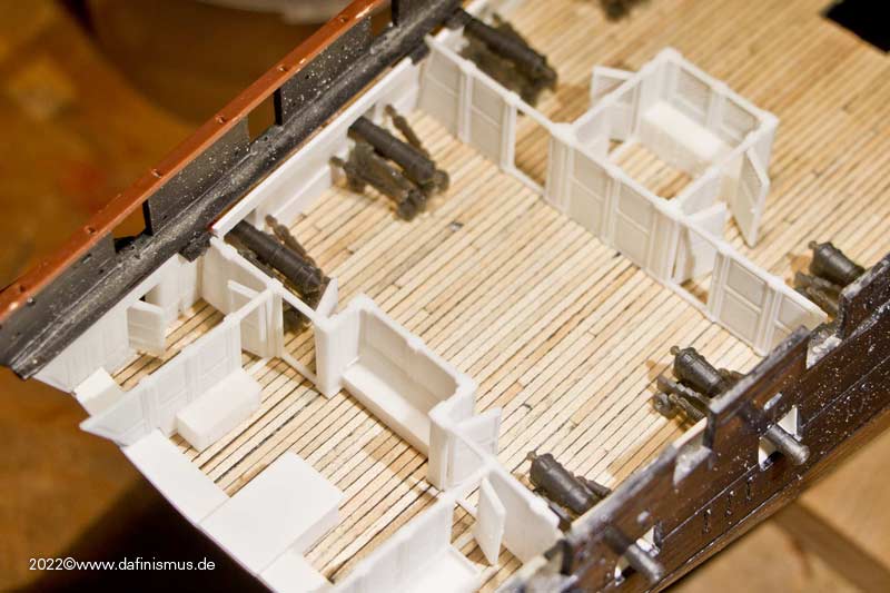
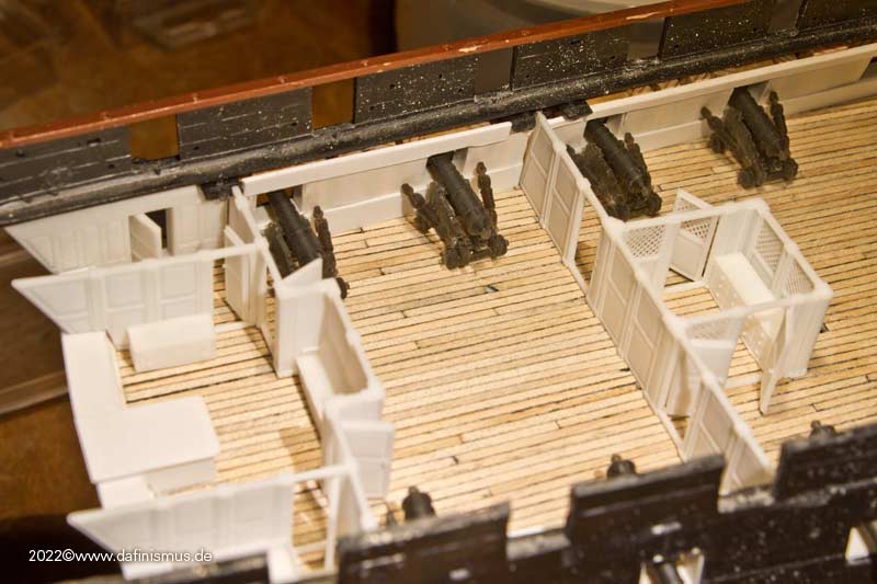
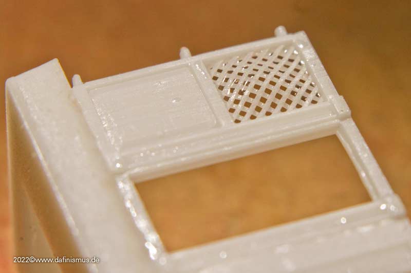
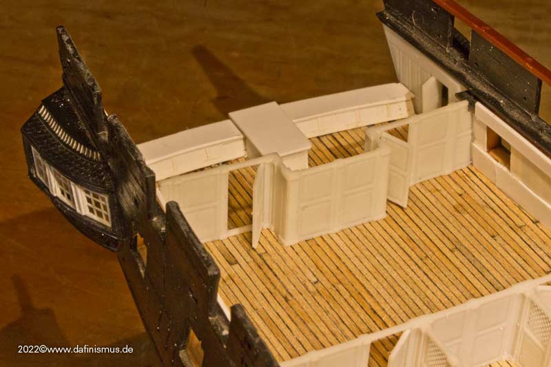
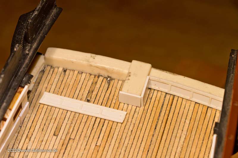
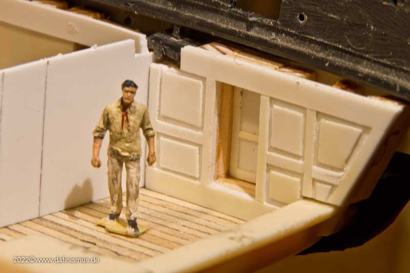
But not to forget the basics besides all the fascination of printing. The next step was the stern cabins layout.
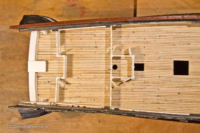
Since the sources about the position of the cabins are quite "soft", I took another look at the situation. In the galley runs the mast and in front of it the rudder ropes. And food preparation should also be there. According to most sources, there is a cabinet with a worktop there, consequently the front edge has been pushed forward and the space for a small cabinet has been created.
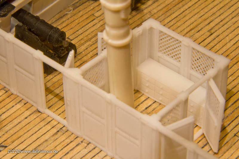
Fits just so with the grating, although I do not know to what extent this opening is historically documented.
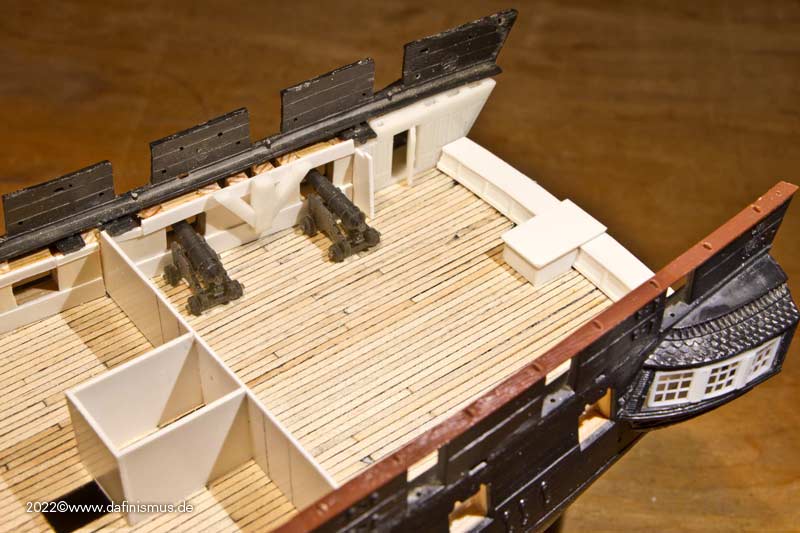
Inside was now the necessary place for food preparation. And doors and guns don't get in each other's way either.
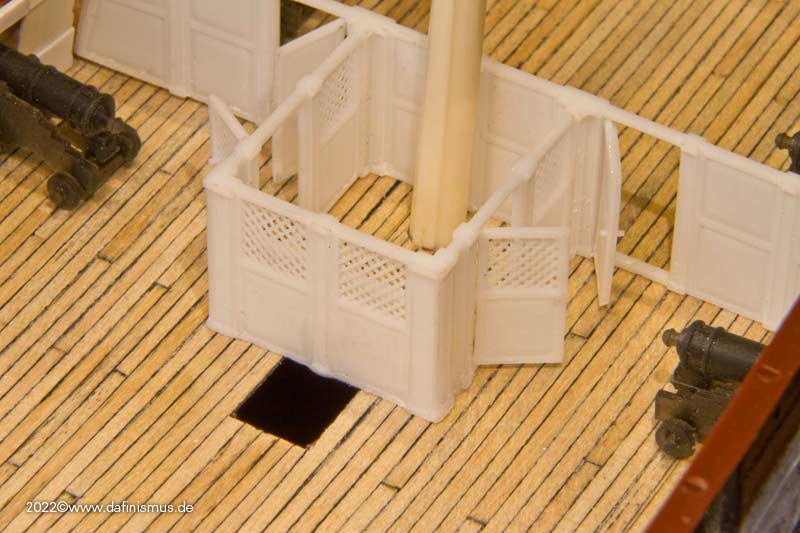
The back of the captain's cabin is also nice and cramped.

For the bed, I did away with the lattice structure and provided a curved entrance in the French style.
The sofa is also now in place.
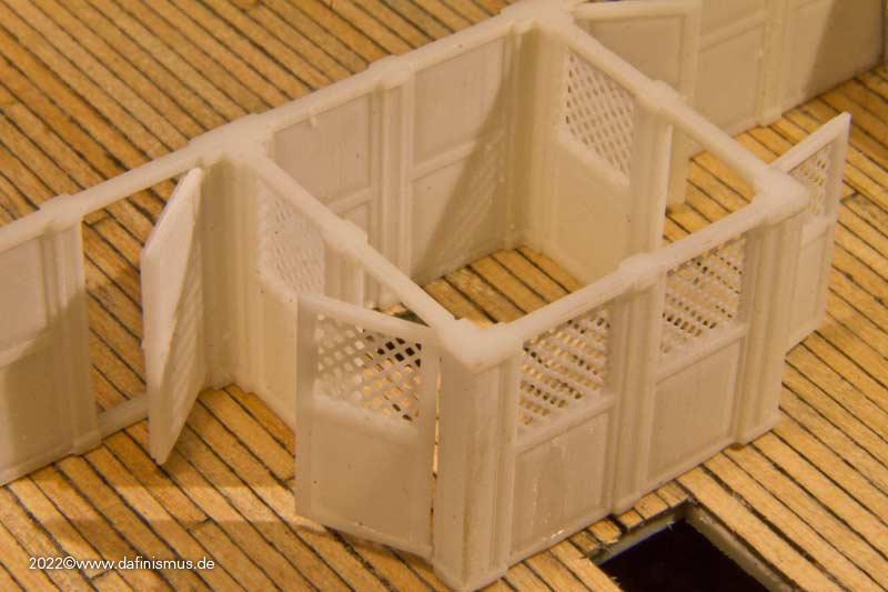
A little side note: I had already mentioned that the lattice structure gets a nice belly when printed, which almost disappears again when cured under UV light.
XXXDAn -
Thank you Jim!
At the weekend was "Dafi home alone". As children are, there was again goofing around to be done.
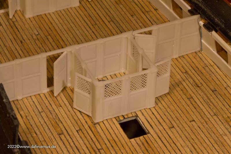
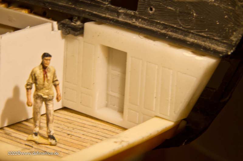
On the agenda was the doll's house in the back. In the kit there is only the bulkheads to the captain's cabin. But contemporary sources still show the bulkheads of the wardroom and the pantry for these two areas. Since the Constitution seems to me like a mixture of French and English influences, I looked at the various templates in the Boudriot as with all the England girls.
Also interesting is this Englishbeauty from the NMM, one of the few contemporary models where you can see the internal bulkheads.
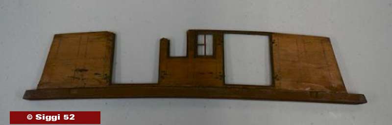
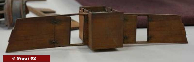
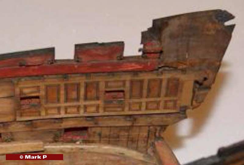
The adaptation of the vertical structures to the inclined ship's side is very nice, but I ended up going with the classic vertical version. Interesting also the change of the height of the subdivision: at the ship's side at the level of the lower edge of the gunports, otherwise almost in the middle.
The first print came out quite usable.
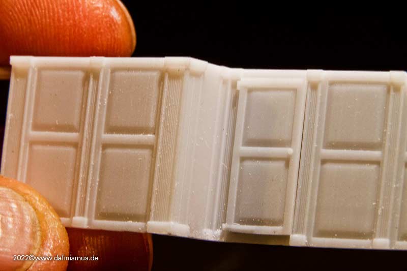
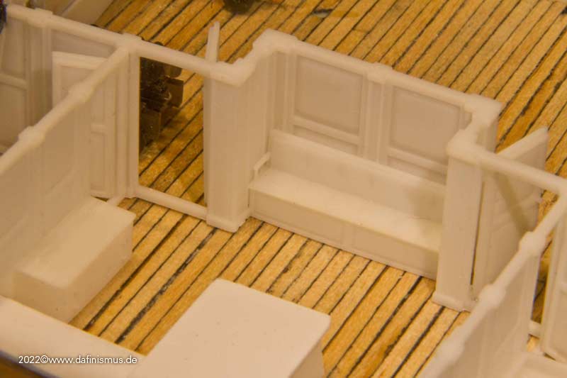
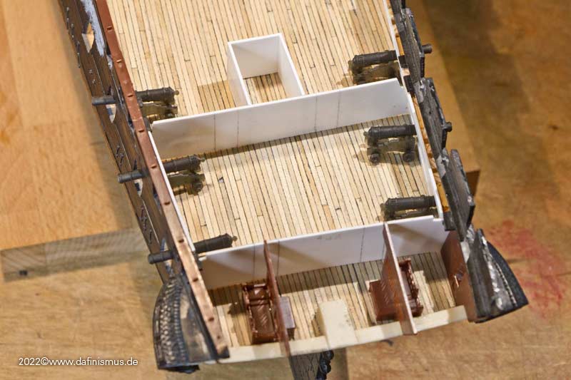
The basic layout looks like this, the bulkheads in the captain's cabin are still missing.
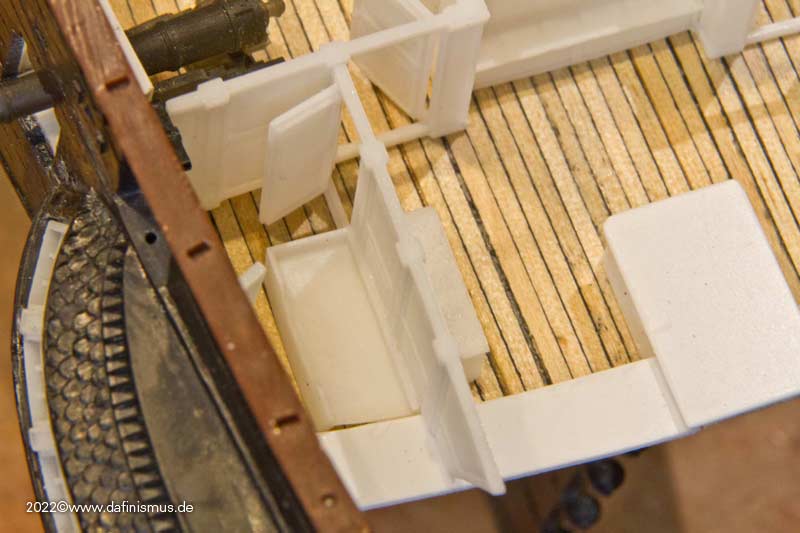
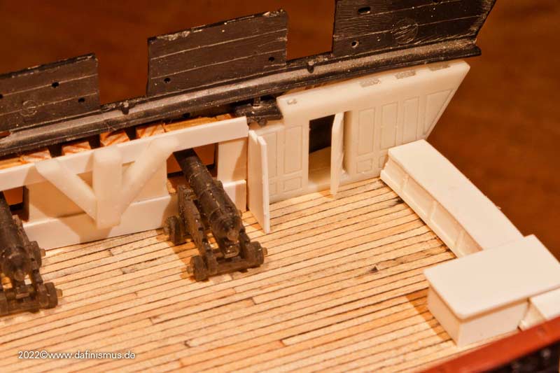
And here are just a few impressions of what can be done. Focus on the bulkhead to the captain's cabin.
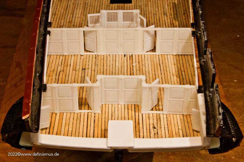
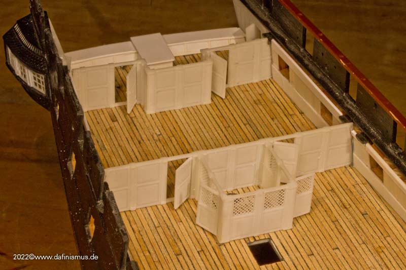
And here are a few pictures of the forward bulkhead and pantry.
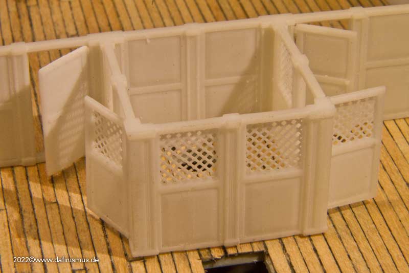
Now it's on to the right fitting 🙂
XXXDAn -
As always thanks for the clicks and comments to the gentlemen and of course the ladies 🙂
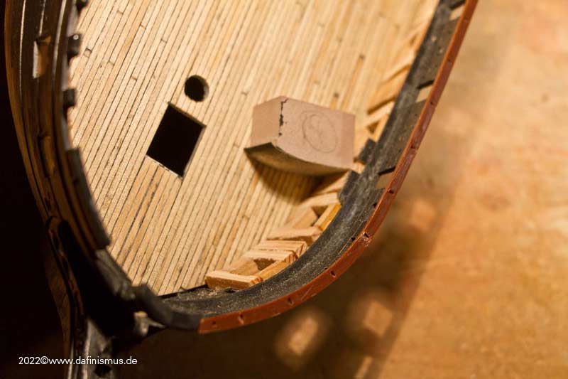
At some point I noticed again the dark hole to the orlop and also how painful I still have to suffer on my Vic because of a similar omission 😉
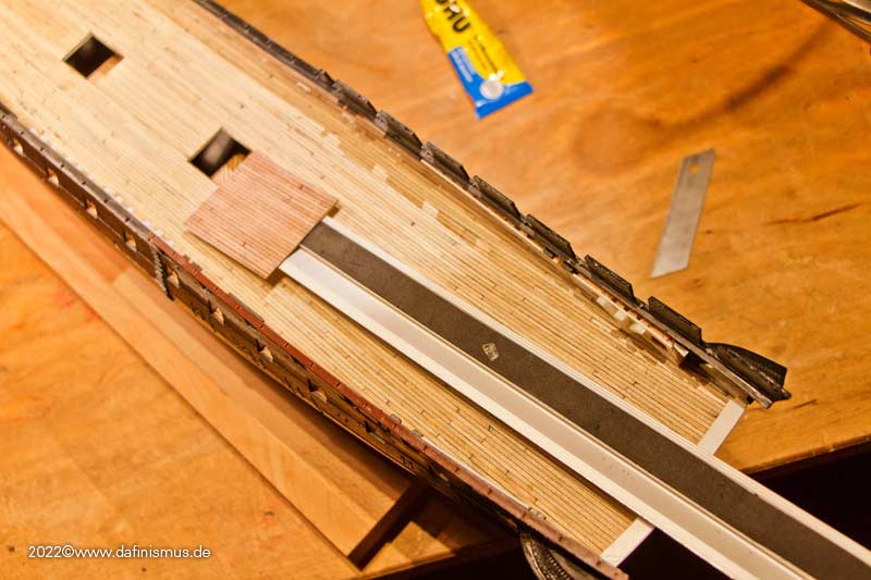
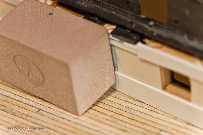
So I prepared two matching blocks, took out the big tweezers ...
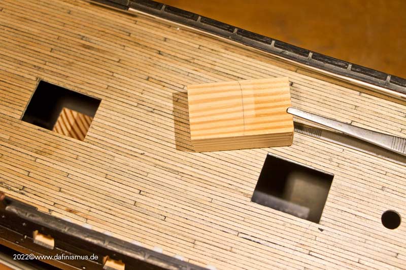
... and sank the blocks from above through the hole into the depth, with huge amounts of glue positioned underneath. In addition, also fixed supports to sides, so that they do not end up later as shaken goods.
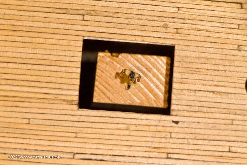
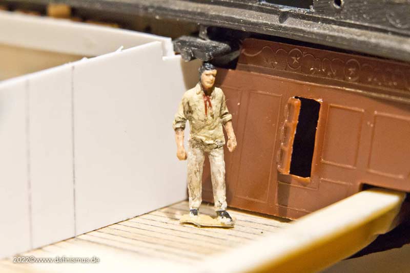
Of course, there was a stowaway right away ...
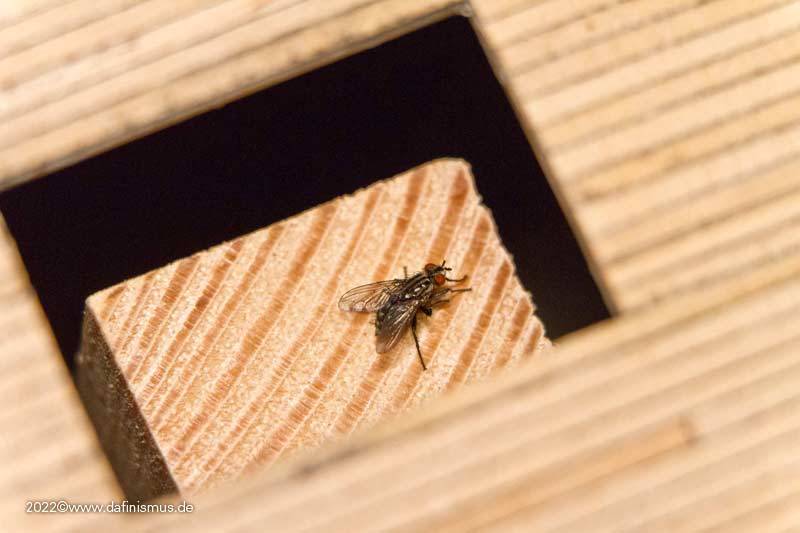
.... which my little brave sailor had to drive away with death-defying courage.
Then prepared the deck ...
... for this purpose photographed a piece of deck and printed it out tiled.
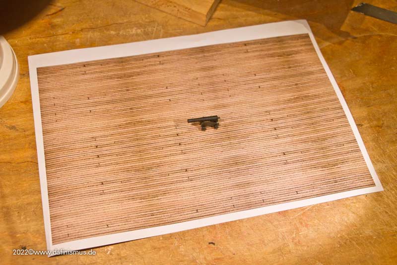
Colorwise I could have done some corrections, of course, but for this purpose it does quite well. I'll put a grating or something similar over it later anyway.
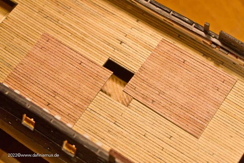
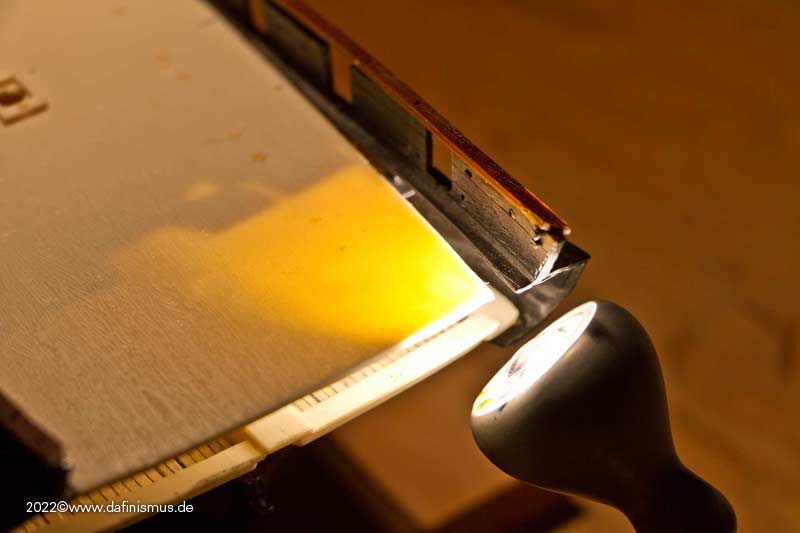
But how to get the parts in there? The prepared piece of deck was fixed with a little double-sided tape to a long ruler ...
... luckily I had spotted the small gap in the stern and with a loud *yikes* rammed it inside ...
... and pressed it into the right place into the glue waiting there, aligned properly ...
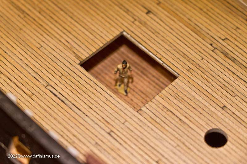
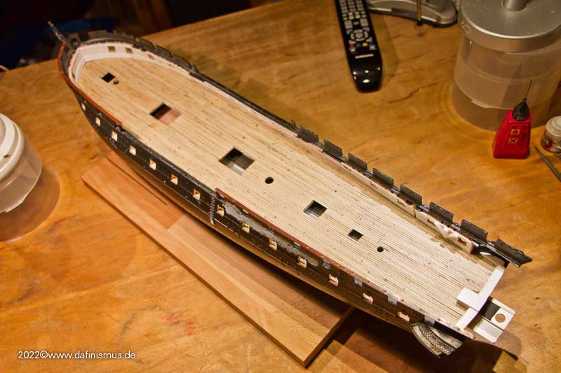
... and let the gentleman of the quality control look over it 🙂
Was accepted so, luck!
XXXDAn -
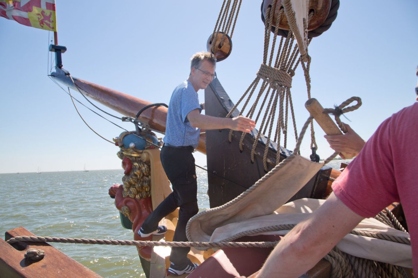
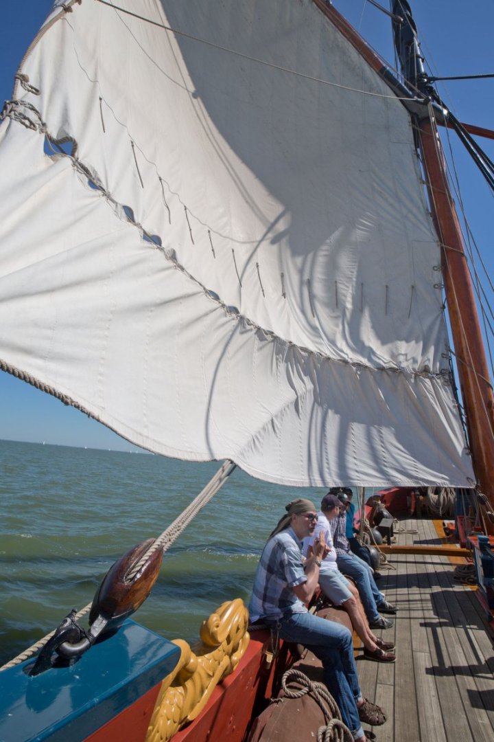
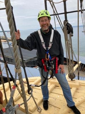
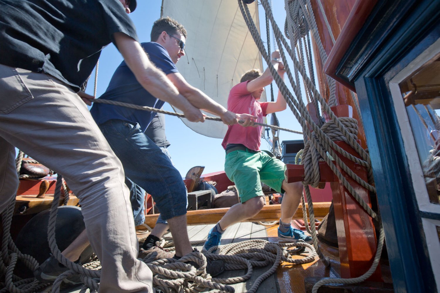
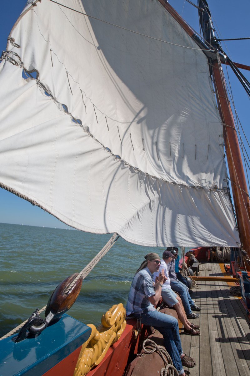
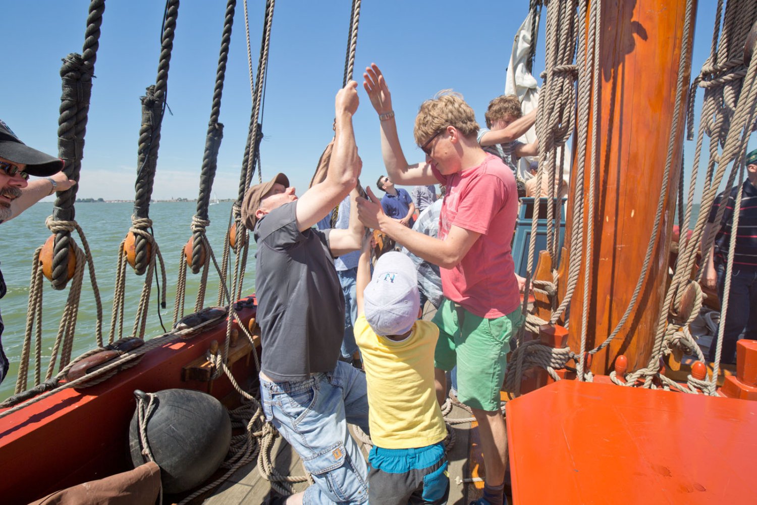
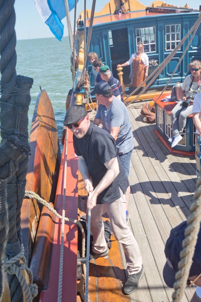
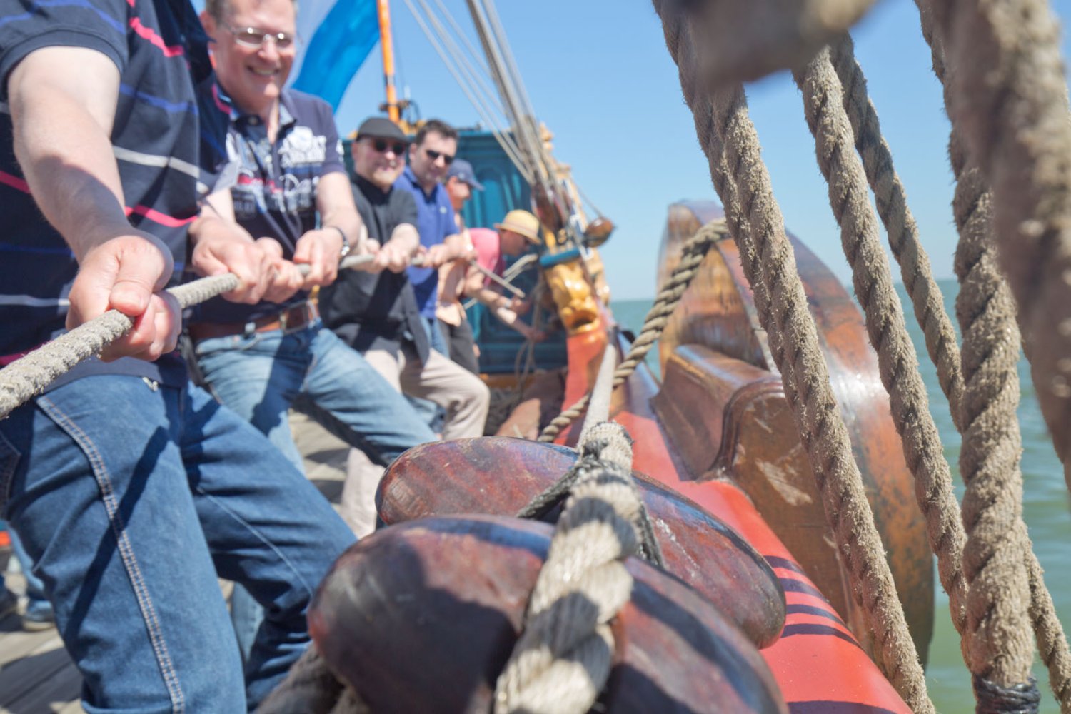
Looks like you are in the States? Otherwise I would have suggested to do a day turn on her, it really is a great event!
We hired the ship in 2017 with friends from our german forum and it was a greaz day out! They also do tours where one just stand in with others, always great fun. For some reasons i did not feel the need to go downstairs as it was too exciting upstairs, so I have unfortunately no pictures from the dining room.


-
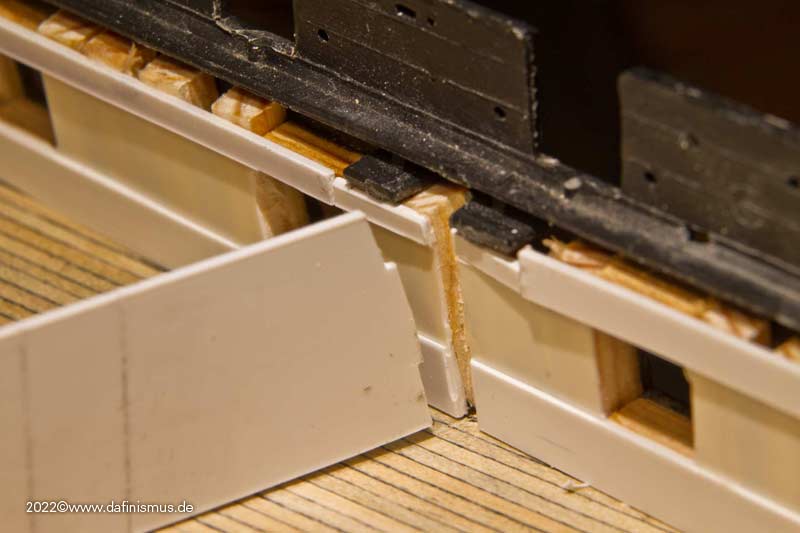
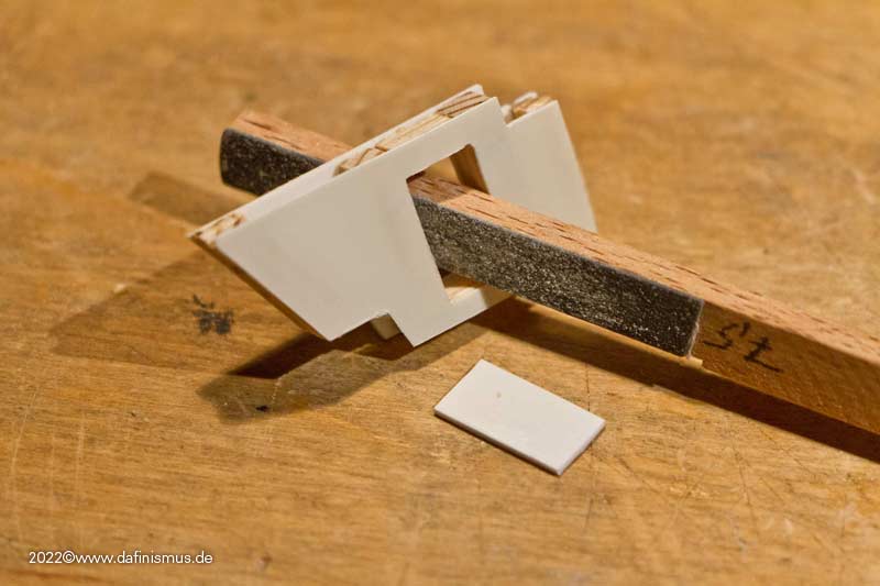
I already mentioned the problem of the bulkheads to the officers' mess and the captain's cabin. Because I still have to press the hull shells together at the top, I don't have a clean connection to the ship's side.
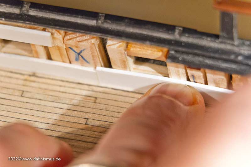
So I marked the beginning of the bulkhead ...
... and made a small slot in the hull. Then the bulkhead can slip in when pressed together and everything is clean http://www.shipmodels.info/mws_forum/images/smilies/icon_smile.gif
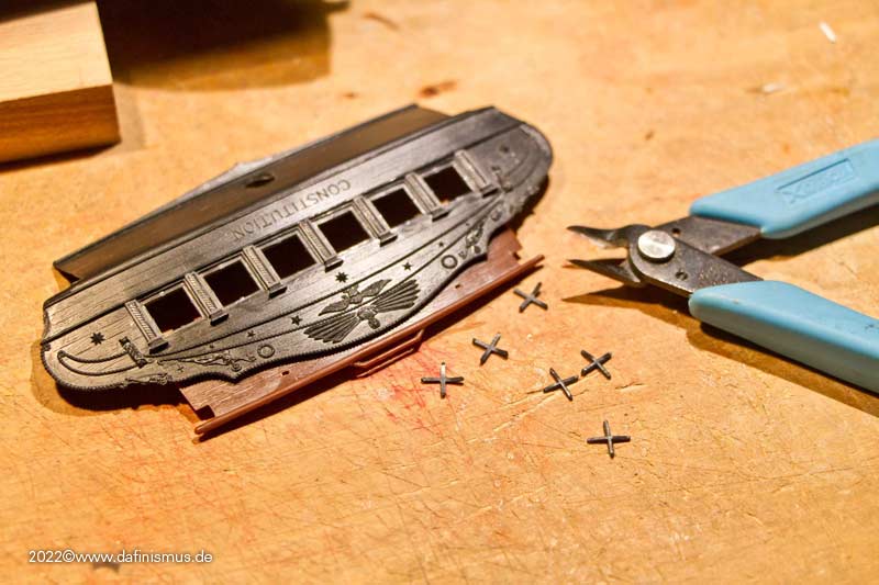
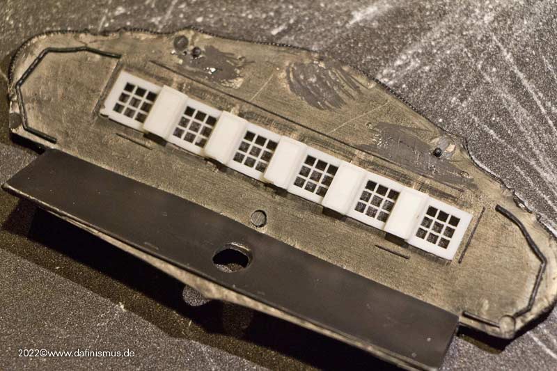
Then up to the next adventure. Window bars were cut out of the rear windows.
And the first two print tests went right off the bat. I'm slowly getting the hang of it.
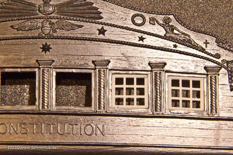
And then the full width, even with the minimum curve upwards in the center.
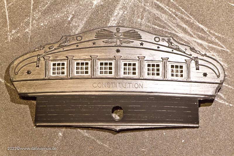
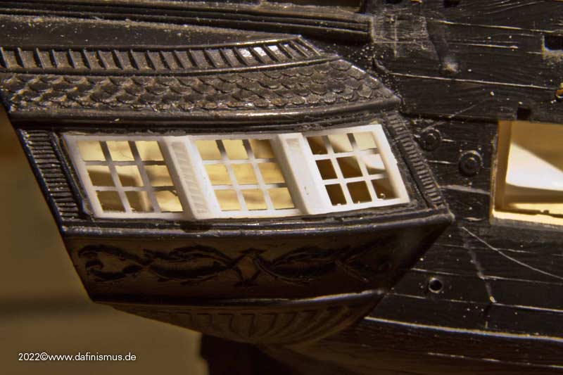
On the inside the frames between the windows also were applied, but I still need to adjust the length properly.
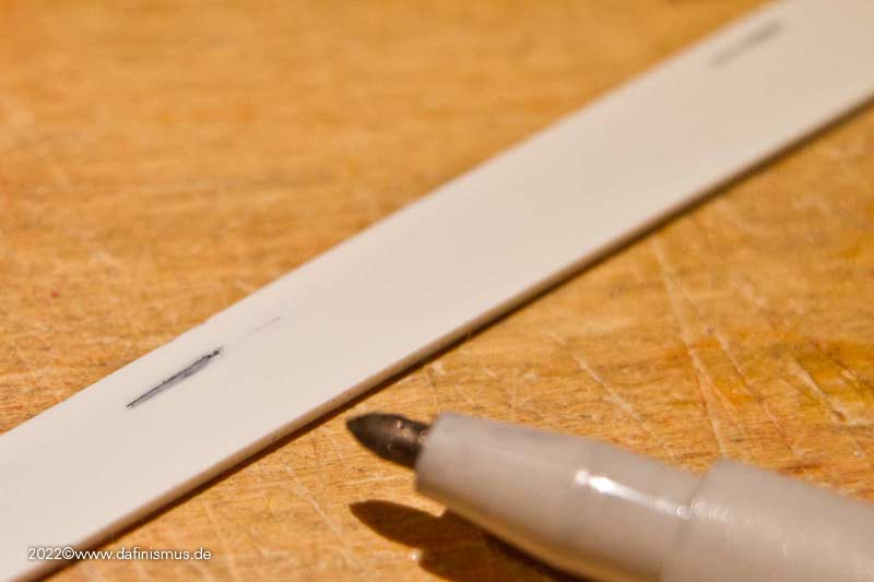
Next were the side galleries. The starboard side even fitted on the second try.
Port side took me two more tries, I had measured stupidly once when trying it on the first time. Probably I held the part upside down. Meanwhile I have a mark on it, so that something like that can't happen.
The paneling of the aft cabin is also a bit more accentuated, below the first try, above new.
The bench seat under the stern windows has been panelled, once it looks better and also hides the base of the planks.
Here then the ensemble, the bulkhead between officers mess and captains cabin is missing. It is only indicated by the small tail. This time I left a slot in time, one can learn. Sometimes at least http://www.shipmodels.info/mws_forum/images/smilies/icon_wink.gif
Cheers, XXXDAn -
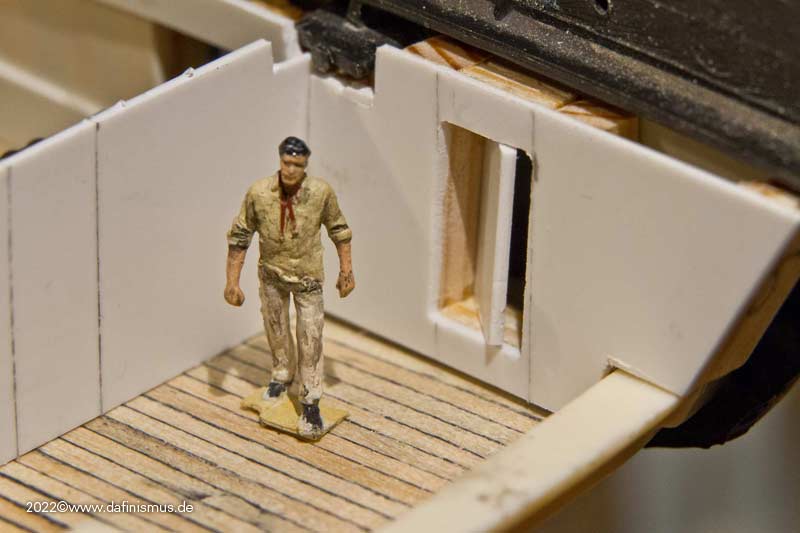
And then it was time for the doll's house in the rear. First of all, the width was determined.
Then the reminder that there is still a lot to squeeze together in the back. So the width must somehow remain flexible, more about that later.
The cabins in the back are represented in the kit, but not the front bulkhead to the wardroom.
The passages into the side pocket is also a bit sporty in size.
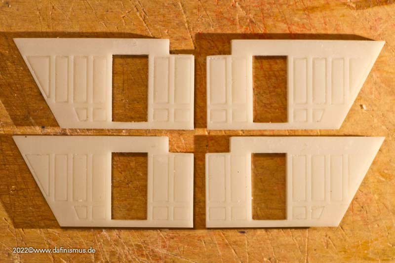
So a quick replica in the right thickness.
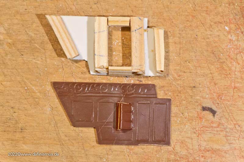
And in place. The door was hinged on the outside of the hull and aft like Boudriot.
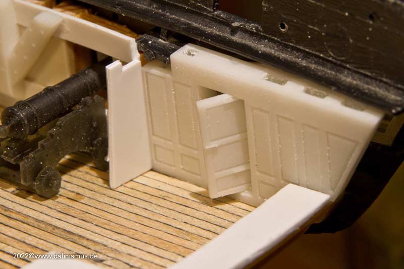
After that came some paneling.
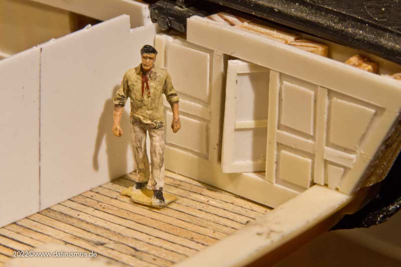
And since that was still a bit too rough for me, a printing test.
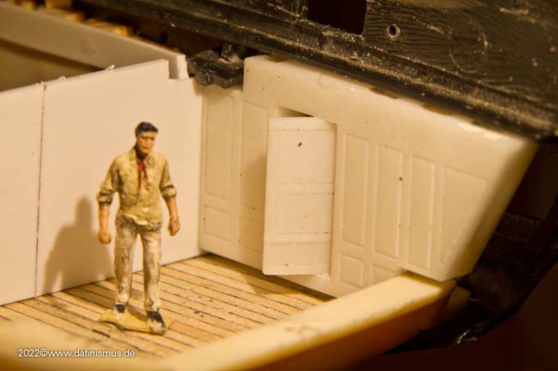
Even if the bottom fit is not yet matched it is already a bit finer in texture http://www.shipmodels.info/mws_forum/images/smilies/icon_smile.gif
XXXDAn -
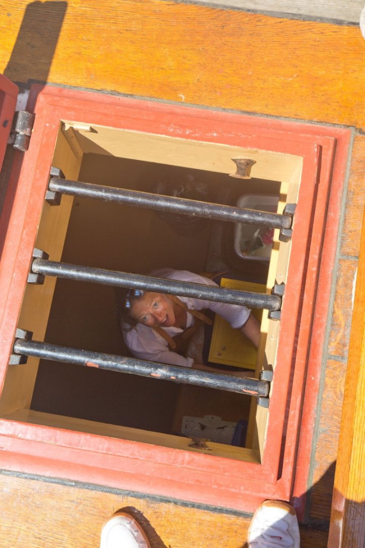
I was very happy using the lubbers hole while going up the Jyland 🙂
Have to admid it was very tight and you should NOT have a tummy to be able to pass there. Also the shrouds are that thight together that ratlines are useless.
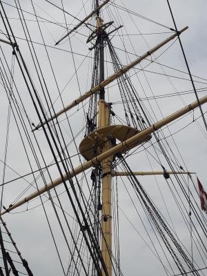
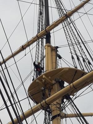
Still I would have liked the experience using the futtock shrouds to get the right feeling. One thing I can confirme, the lubbers hole is a bottle neck and if a whole crew has to climb up with speed, the only way to get them up in a reasonable time is the way over the edge.
Most models miss the upper two rows of ratlines, those should go even over the irons, not like the first picture in this thread, having this enourmous gap on the top.
XXXDAn
-
In the meantime, the bow is paneled. After the "take photo without card lock" of the camera was turned off, I am missing the pictures of the open subconstruction ...
First as usual the frame imitations inserted, then the whole thing was paneled.
Since the anchor cable hatches are also misaligned, those were closed up right away as well.
XXXDAn -
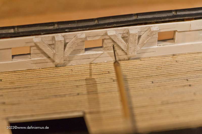
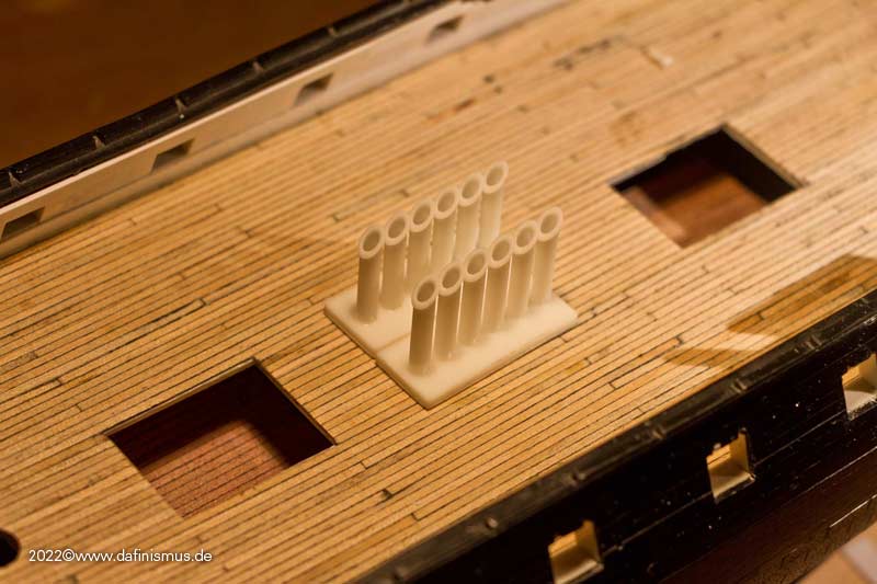
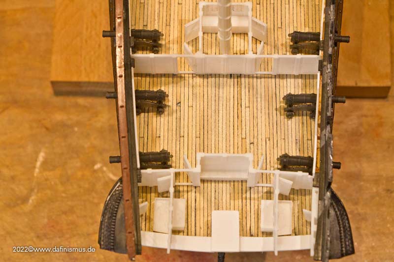
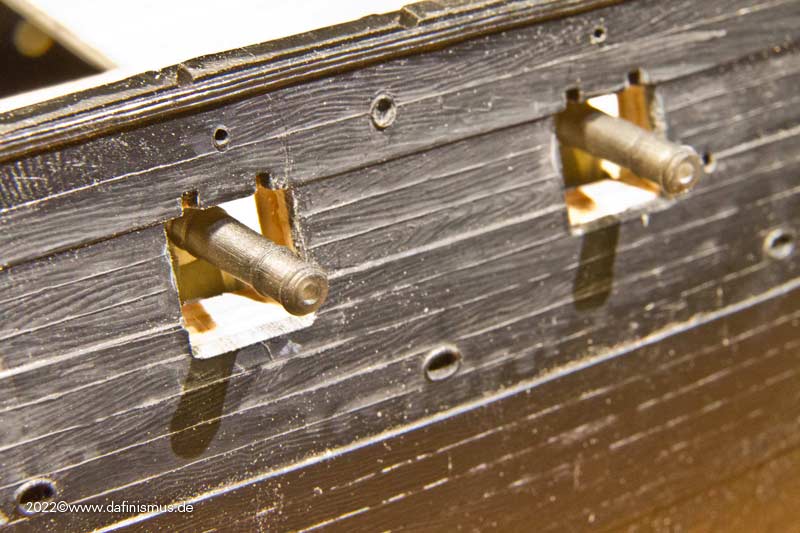
In order to get a little more structure into the few possible views into the lower deck, I have printed the characteristic triple knees of today's Constitution. Whether these were already in place in earlier eras of the ship or if they were only installed during later conversions is beyond my knowledge. I would have instinctively guessed the classic use of 3 separate knees for the early phase of the ship. I would be happy to take any hints on this.
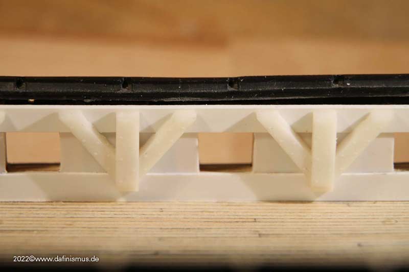
Due to the kit, I can't work with deck beams because the ship has to be pressed into shape by the upper deck. Therefore, I have to skip the upper part of the knees too.
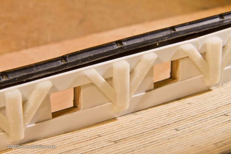
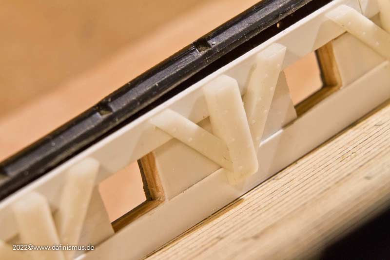
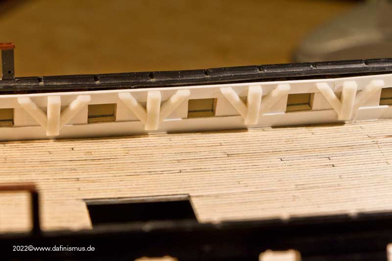
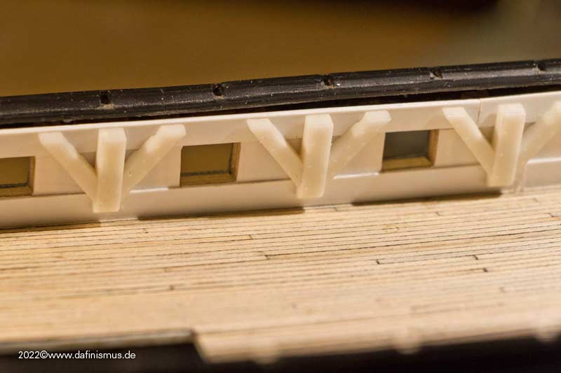
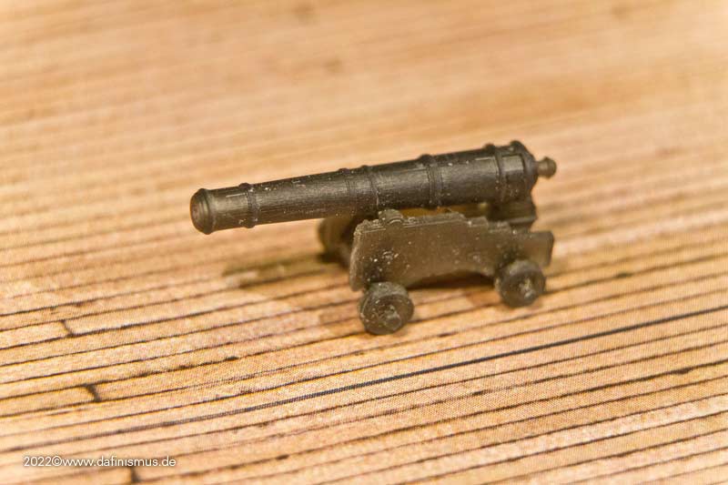
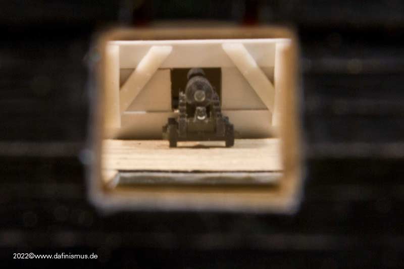
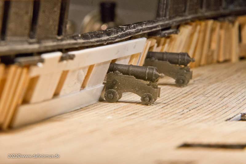
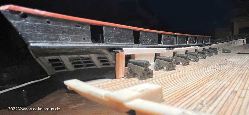
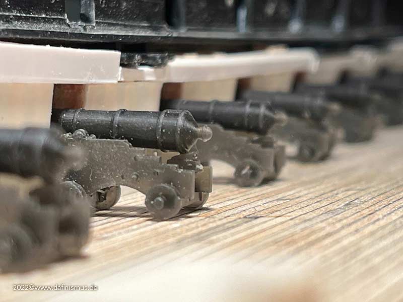
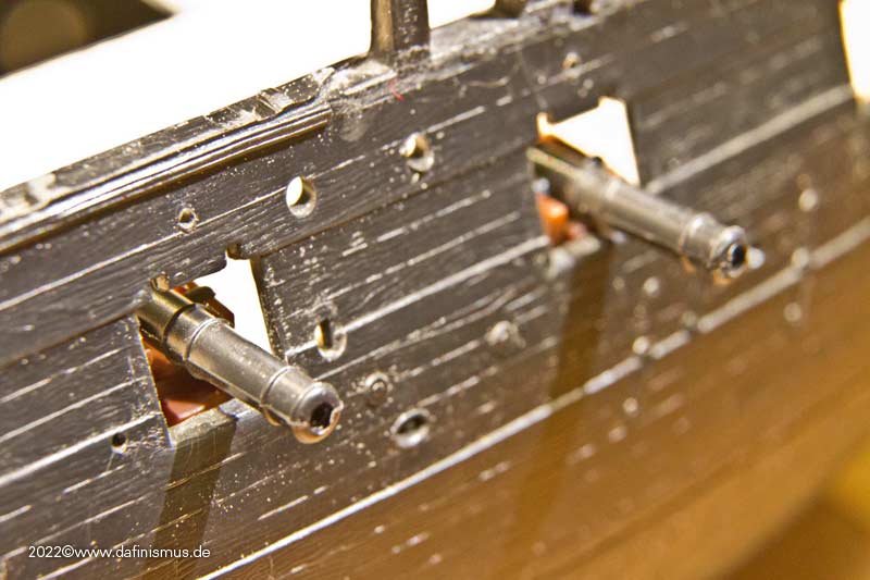
Placement check with guns.
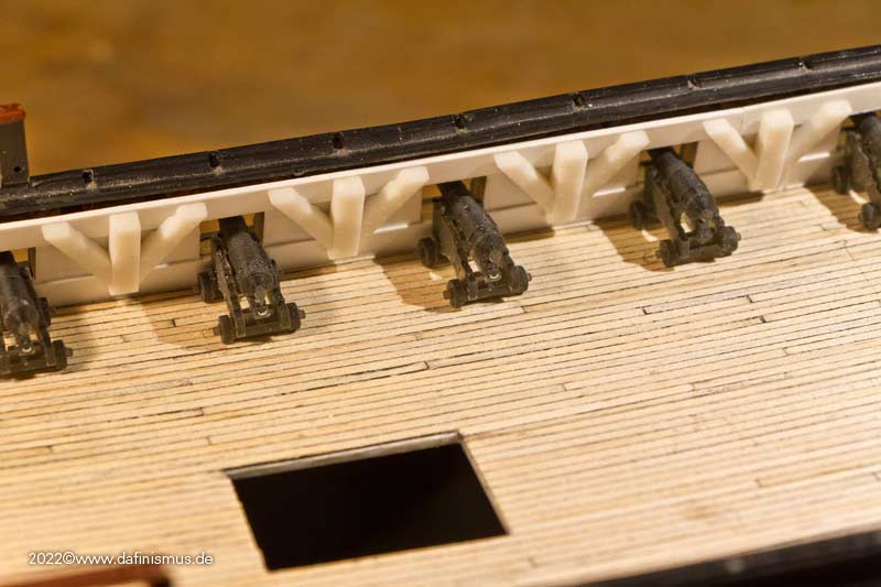
And in the end it's all about such a view anyway http://www.shipmodels.info/mws_forum/images/smilies/icon_smile.gif
XXXDAn- Jeff T, CODY, mort stoll and 7 others
-
10
-
I do not see more problems coming. It even can happen, that the "inner planking" can deform the hull even more. But that has to be corrected with the upper deck used as stabilisation factor.
XXXDAn
-
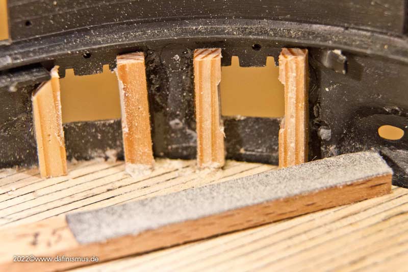
After all the battens were mounted, the cleaning up really started. Rough overhang was minimized with the scalpel, then the top and bottom were filed with the sandpaper battens as already described.
I also made a small tool for the inner surfaces.
For the bow area there was something more shorter and rounded.
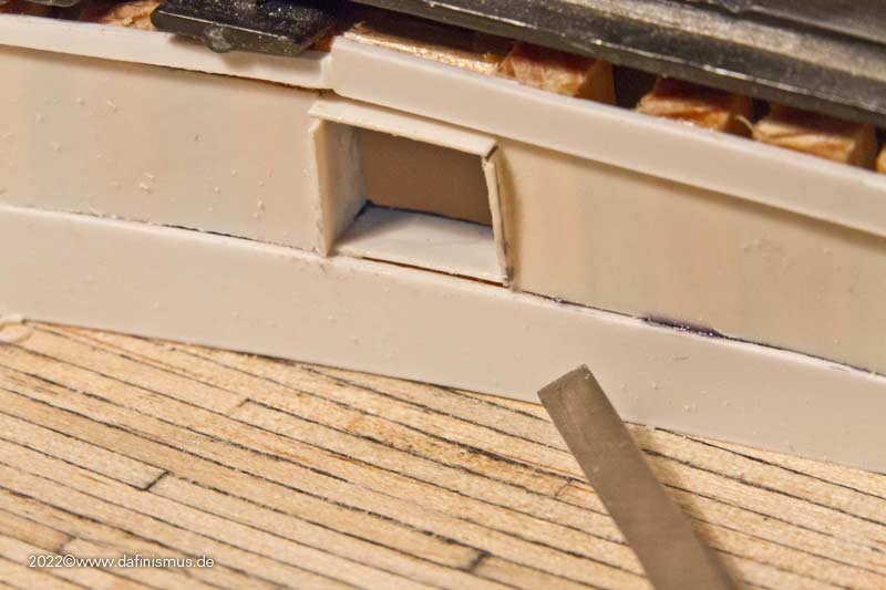
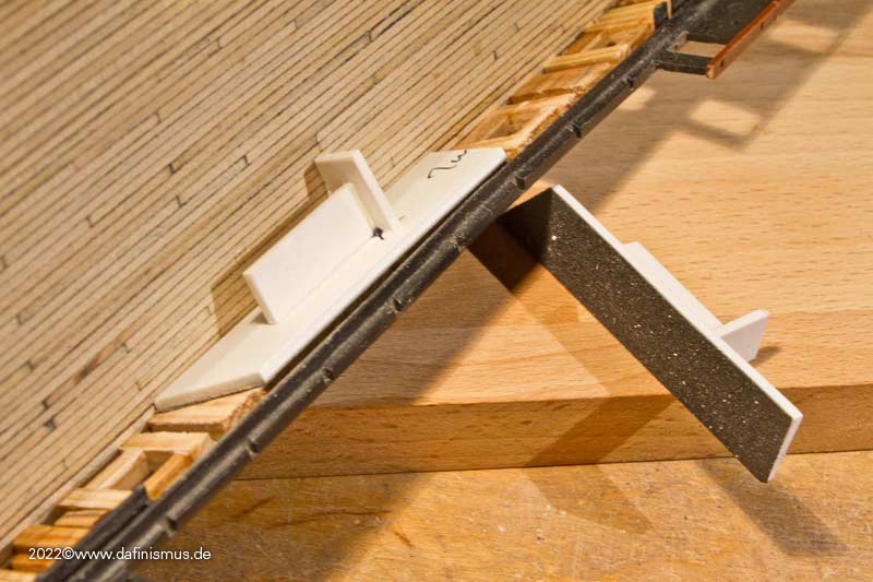
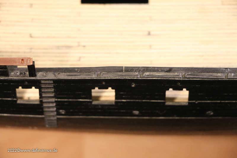
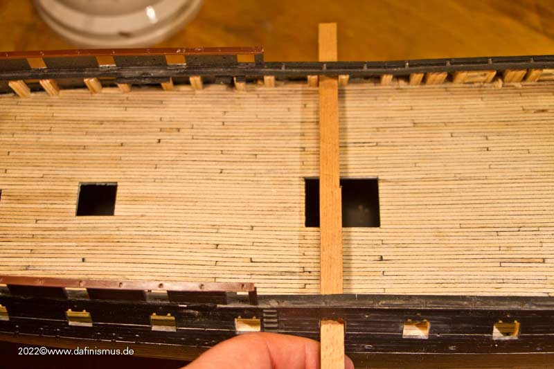
After everything was smooth enough we went to the spirketing. A 1 mm thick polysterol strip at the bottom, 0.5 mm Polsterol between the ports, and another 1 mm above that.
And the fit sample.
Fits http://www.shipmodels.info/mws_forum/images/smilies/icon_smile.gif
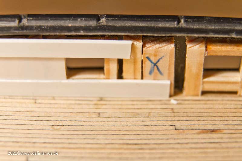
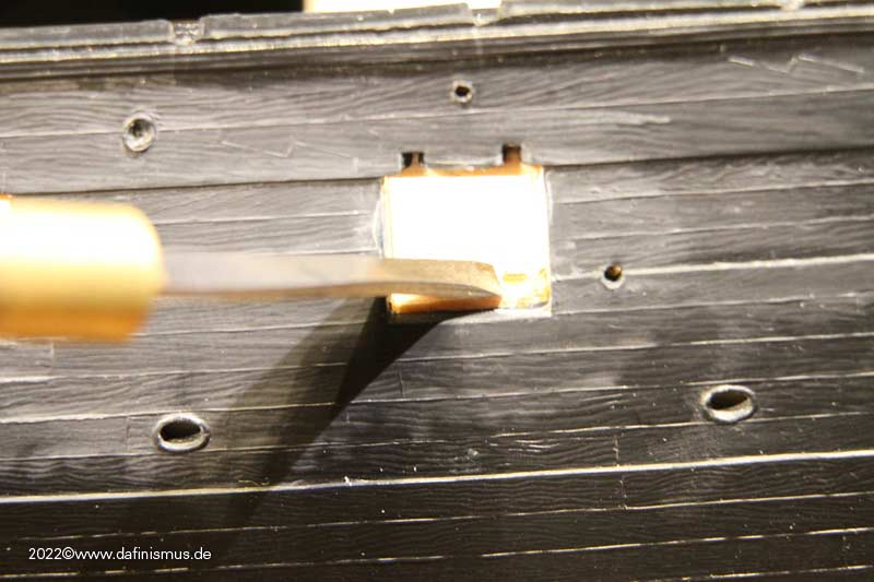
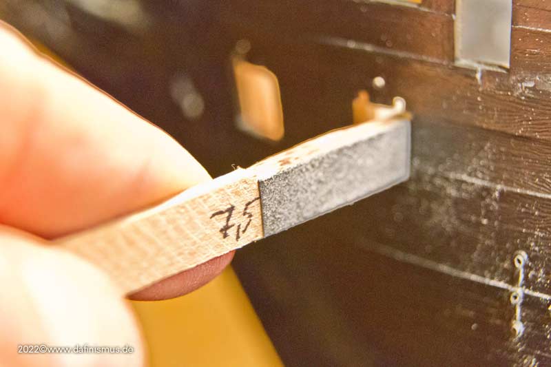
To fit the lower strip, press it well inside ...
... on the outside, score the lower edge of the port with a scalpel ...
... make the scribe visible with paint, i.e. color it and wipe away the paint on the outside so that only the depth of the scribe remains colored ...
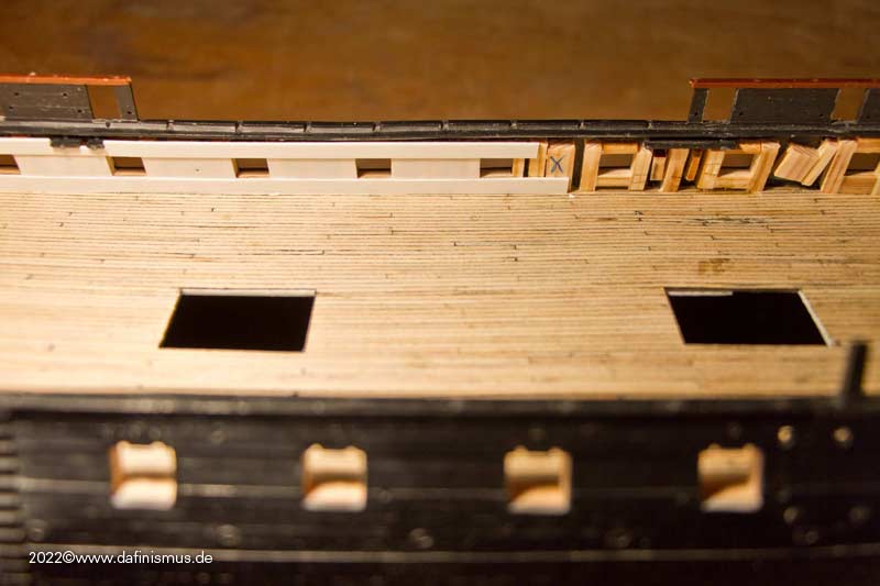
... and cut off the overhang based on these marks and glue this adap´ted stripe in. Between the ports, orient the 0.5mm strip to the height of the ports. If you have worked evenly when filing the ports should be always the same height.
And the one side is ready.
Now the other side and then the head area and the side galleries areas.
XXXDAn- Ian_Grant, Prowler901, druxey and 6 others
-
9
-
I'll come back to the Battle Station later to still add some life. But it was time to do some stretching.
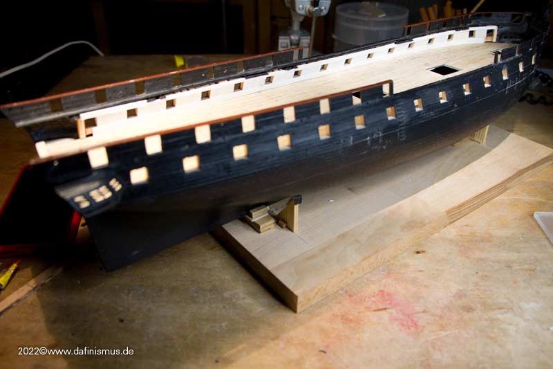
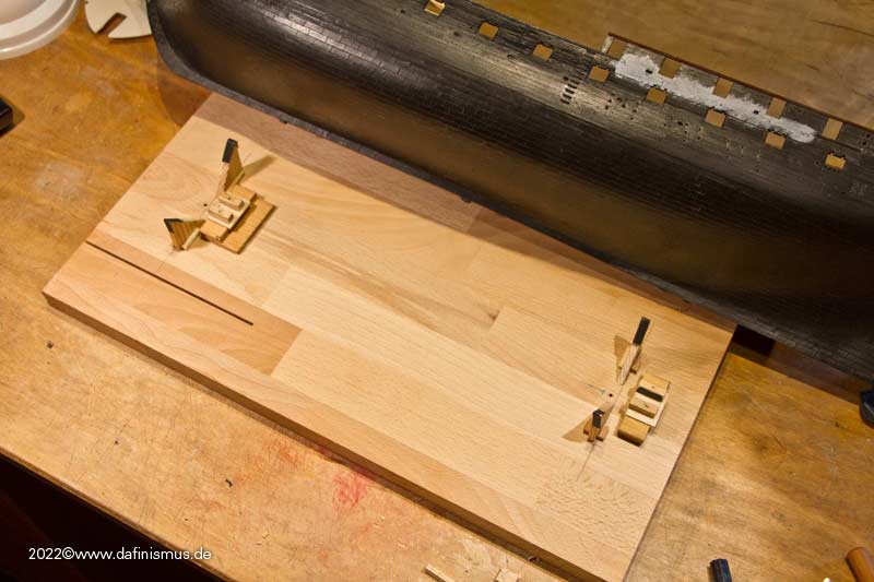
First off, built a sturdy stand.
Then came bondage. The hull is unfortunately so warped, that here rougher force in the form of tight lacing had been necessary.
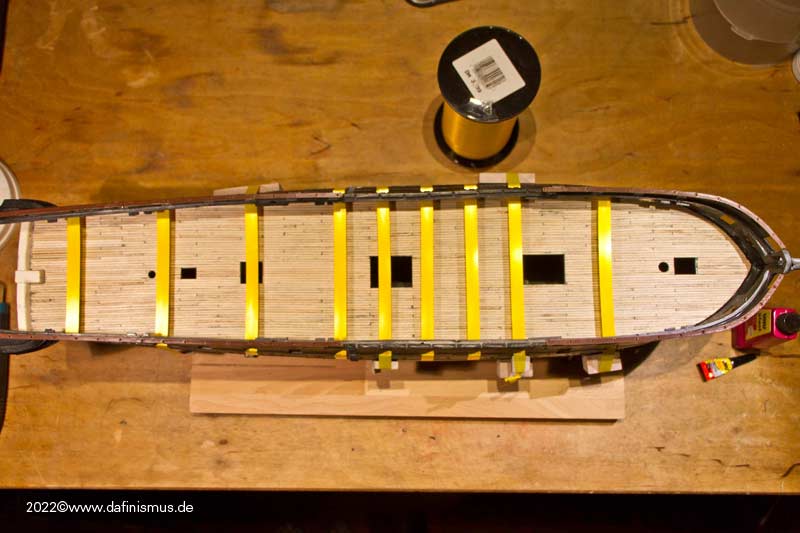
The lacing allowed me to spread the load better. Still, later the hull partially burst open again, so the rougher tools came into play. Result was that it finally lasted ...
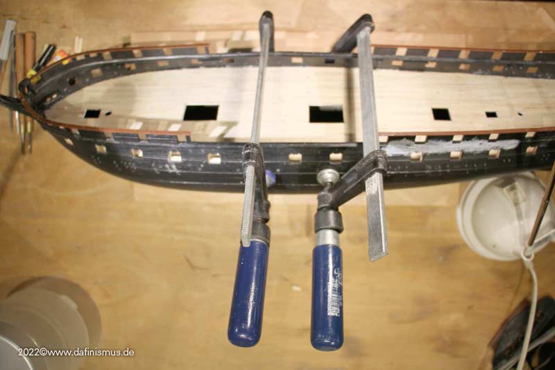
... but as collateral damage the hull had become quite wavy. Later on, the insertion of the upper deck will be a even-ing challenge http://www.shipmodels.info/mws_forum/images/smilies/icon_wink.gif (Mark the bun!)
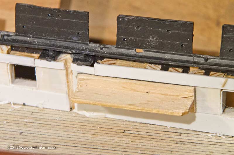
The next step was to double up the ship's side. This makes the difference between the appearance as a classic plastic kit and upscale modeling appearance. Built up a small stop to do the doubling.
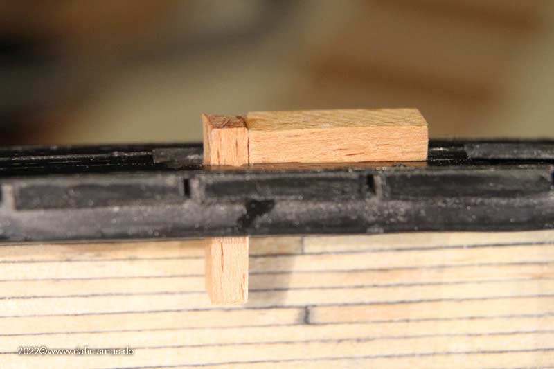
Then glued inside 4 mm battens against the stop.
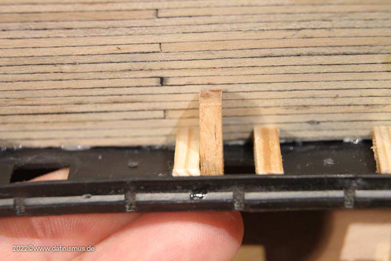
Then inserted the sills at the top and bottom, making sure that there is enough overhang in each case. The space between these port frames was also filled with battens.
If there is too much protrusion of the sills, this is first minimized them with a sharp tool.
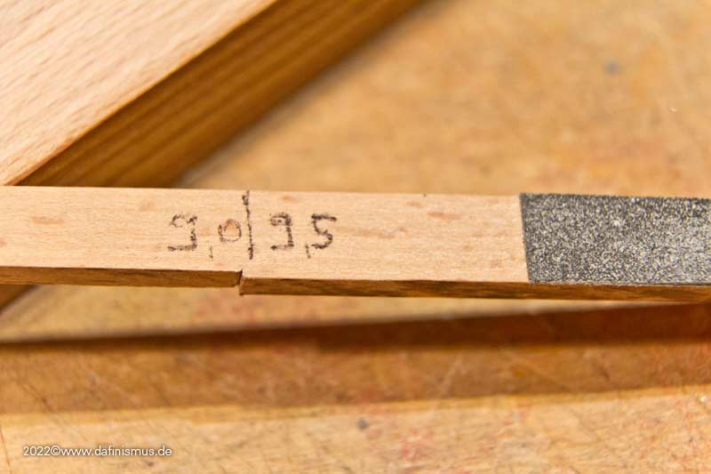
Then cut a flat batten to sand down the remaining overhang at the top/bottom, with minimal undersize in the sanding area and slightly more on the opposite side port. Taped 240 grit sandpaper to it with double sided tape, that fits well with my rather soft battens.
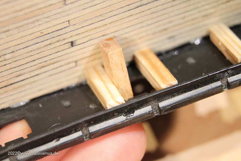
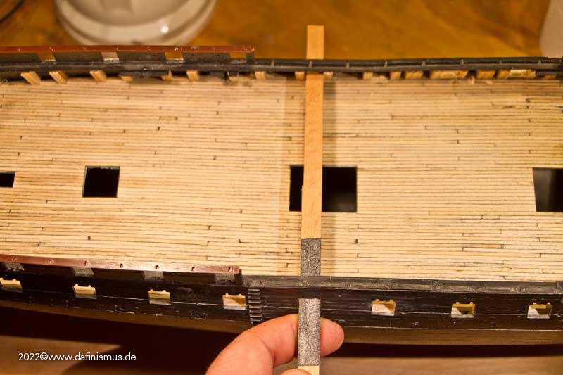
The strip is passed through the port on the opposite side, this gives an even horizontal angle.
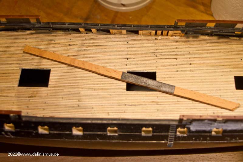
Then sanded the sill on top ...
... turned the batten over and sanded the bottom sill.
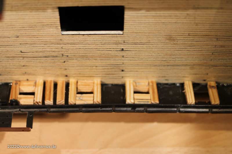
Prepared another sanding strip for the sides ...
... especially in the bow area at the idle ports, some rework is needed because of the strong bend.
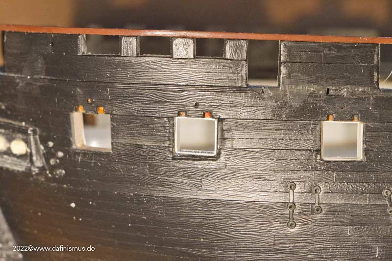
And this you get as comparison: original version Revell ...
... and the revised version http://www.shipmodels.info/mws_forum/images/smilies/icon_smile.gif
XXXDAn- rybakov, mort stoll, Ian_Grant and 7 others
-
10
-
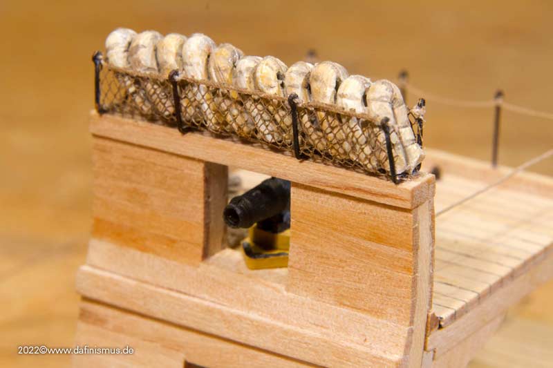
The dimensions of the hammocks are well known. The diameter of the rolled sausage also can be seen in contemporary drawings. Even if they were sometimes thicker, because blankets were still rolled in, I choose the thinner version without additional content. Contemporary sources show 7 to 9 laces. Some say like the 7 oceans, on Bray's sketches you can see the variant with 9.
The mats were rolled of Fimo, the laces rolled in by means of a special comb. Since the holders are very low, I first tried the straight variant.
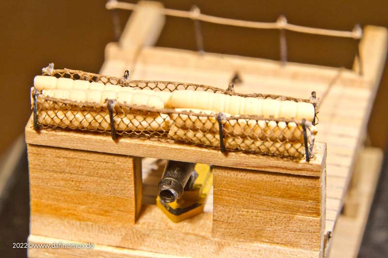
I found the bent variant better, as it is also historically documented in many cases.
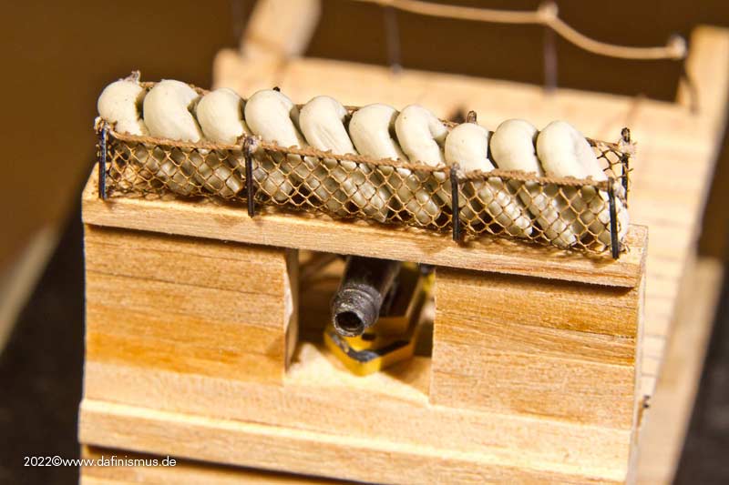
After that, a bit of 50 shades of beige , plus some ink for shadows and depth and the lacing in the visible area represented with thin yarn and it all fits so far for me.
XXXDAn- Prowler901, mort stoll, T. Alex and 4 others
-
6
-
 1
1
-
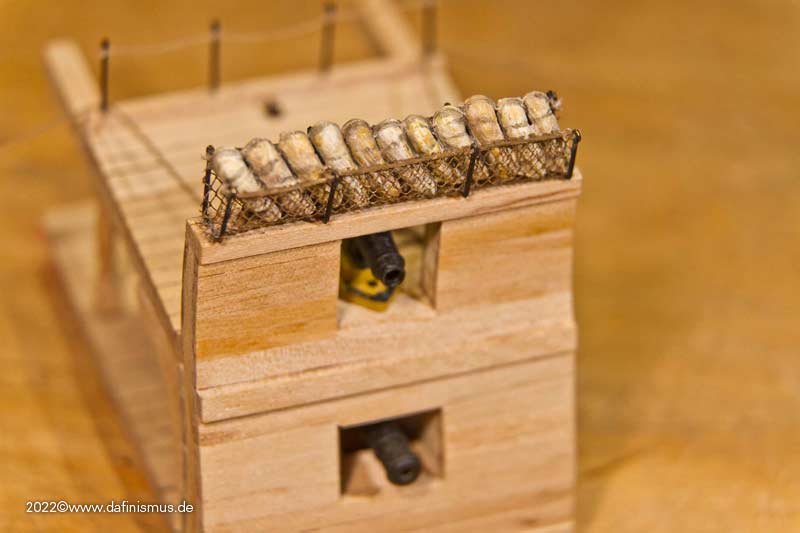
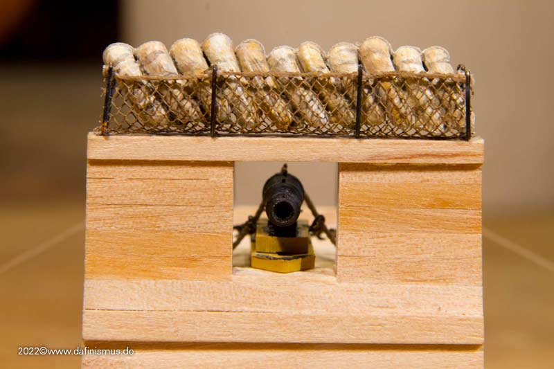
Then attached the hammock cranes with the netting.
Mounted the white net in the cardboard frame and first primed it with white and then colored it slightly brown.
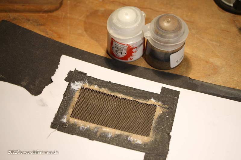
Then inserted two strips of paper as a convenient insertion aid and inserted the net with a wooden core.
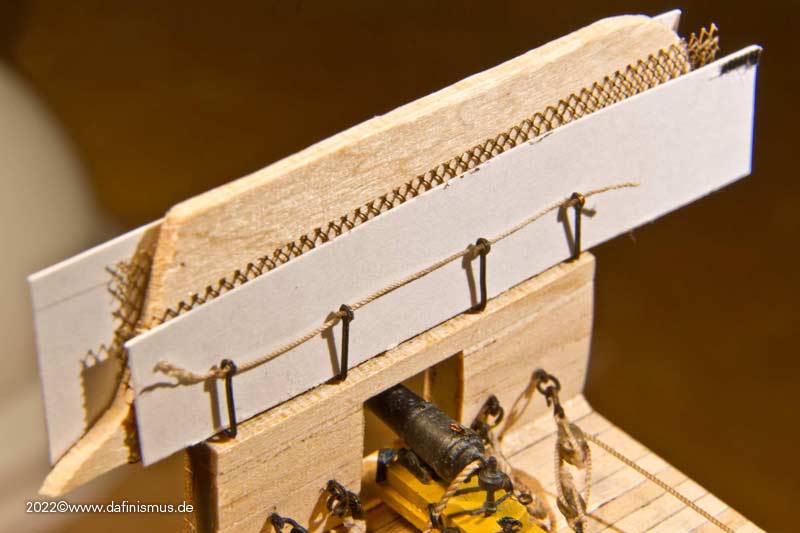
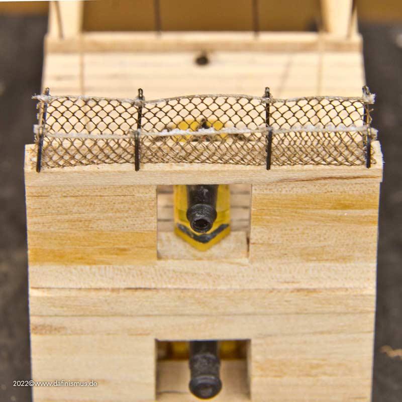
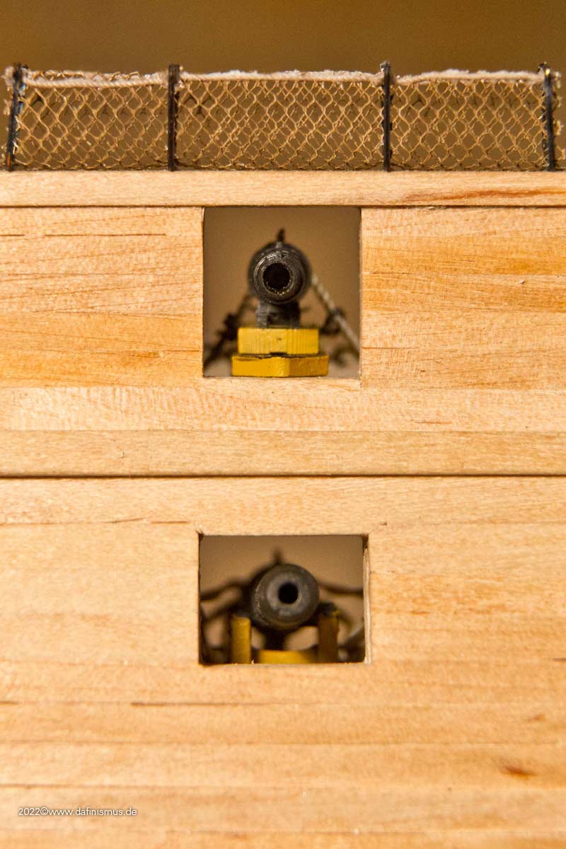
Then on the outside, fixed the net with super glue at points, widened the core so that the net fits well on the inside of the holders, and also fixed the back side of the net at points. Then removed the core, glued the net well to the top rope and trimmed everything well with the pointed scissors.
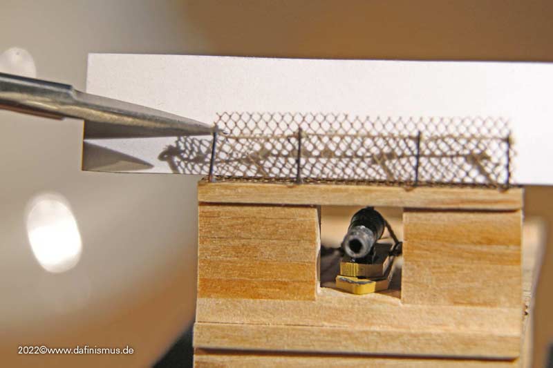
After that, some more trimming was done and next comes the hammocks.
XXXDAn- Prowler901, mort stoll, mtaylor and 5 others
-
6
-
2
-
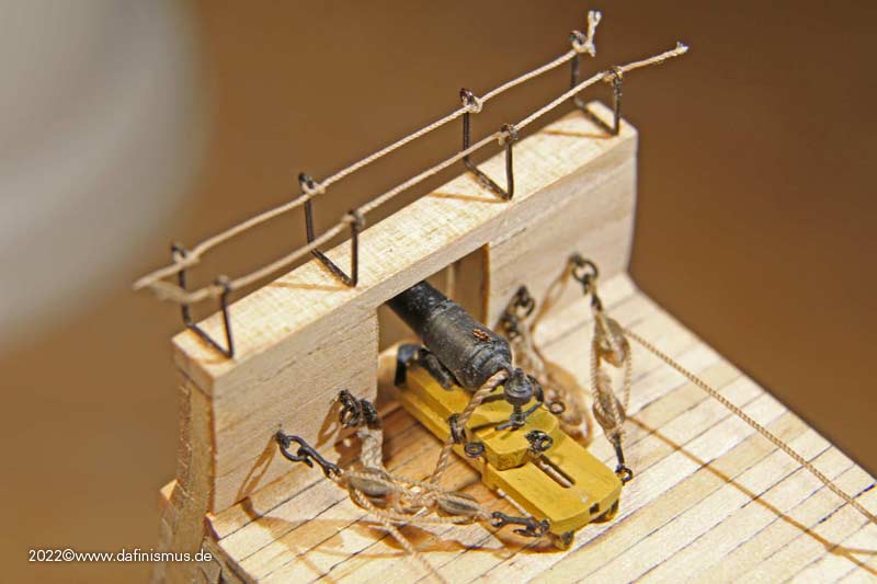
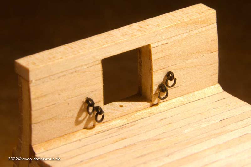
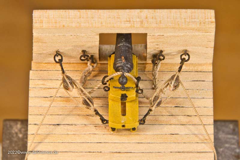
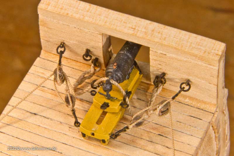
In addition to the figurehead of the Victory, I also made some progress with the battle station of the Constitution. First attached the eyebolts for the carronade's gun rig.
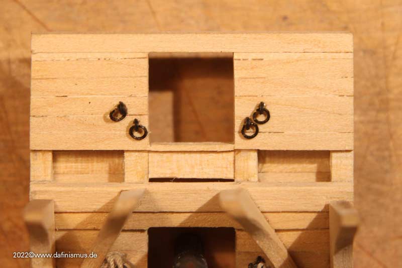
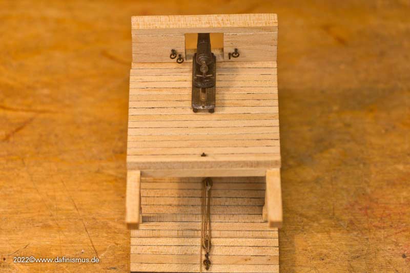
To determine the length of the tackles I again documented the different positions.
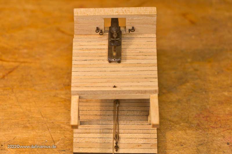
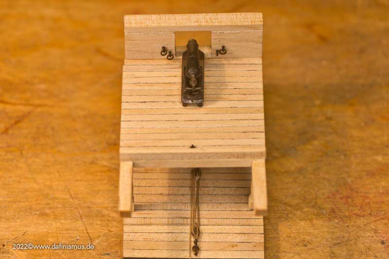
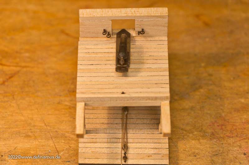
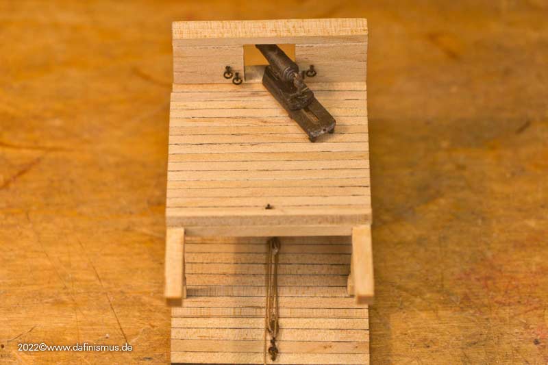
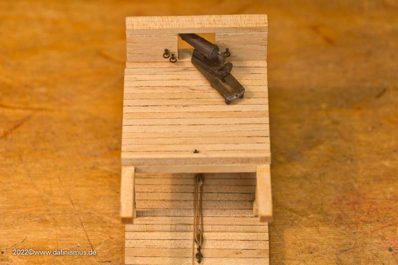
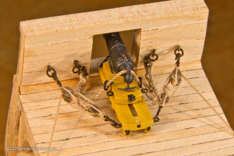
In the last two pictures, it can be seen that the hooks for the tackles are too close to each other to work effectively because the angle is too tight. That's why two more eyebolts are needed further out.
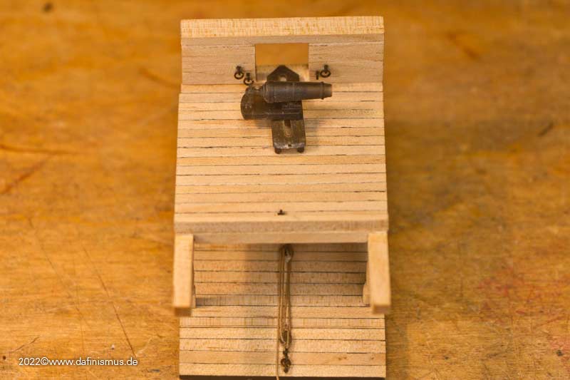
While this position is technically possible, I think it is a special case that can be well achieved with handspikes if needed.
To tie the breechline, I built a small rigging aid. Hammered in two nails spaced at width of the eyebolts and fixed the carronade in maximum aft position. Then tied the two rope eyes, nice and tight around the nails.
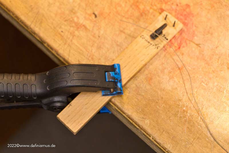
After tying the eye, just pulled them out over the top of the nail, bent the rings up from the eyebolts on the bulwark, removed them, slid them through the eye of the rope, bent them closed again a bit, and reattached them to the bulwark in the eyebolt.
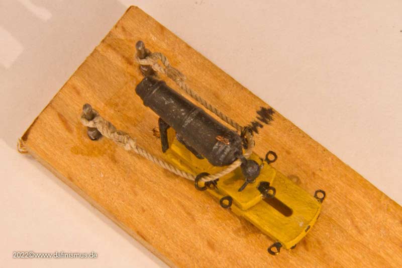
Looks like this then http://www.shipmodels.info/mws_forum/images/smilies/icon_smile.gif
XXXDAn -
Thank you all for the nice words!
After the stressful pre-Christmas period, I actually managed to leave the computer on the side for almost 3 weeks. At least I just managed to finish the programming of the 1803 figurehead of the Victory
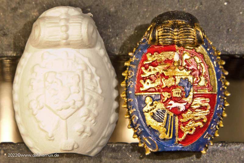
Now here is the addendum from Käpt dafi, who was really looking forward to the painting. Attached are the parts as they came out of the printer.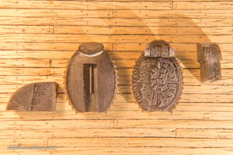
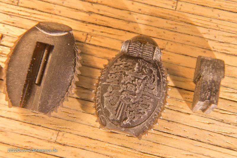
The motto "Honi soit ..." is already imprinted, but with the etched parts it comes a bit more concise, so scratch out one letter at a time, with a thin wooden stick ...
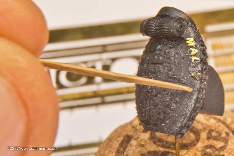
... set some not immediately setting superglue to the respective place ...
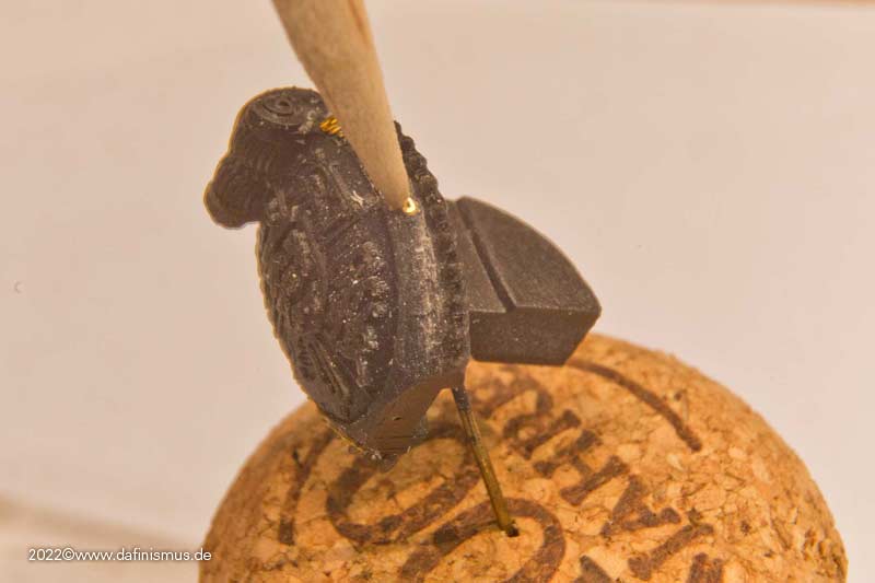
... using another stick to move the letter to the right place ...
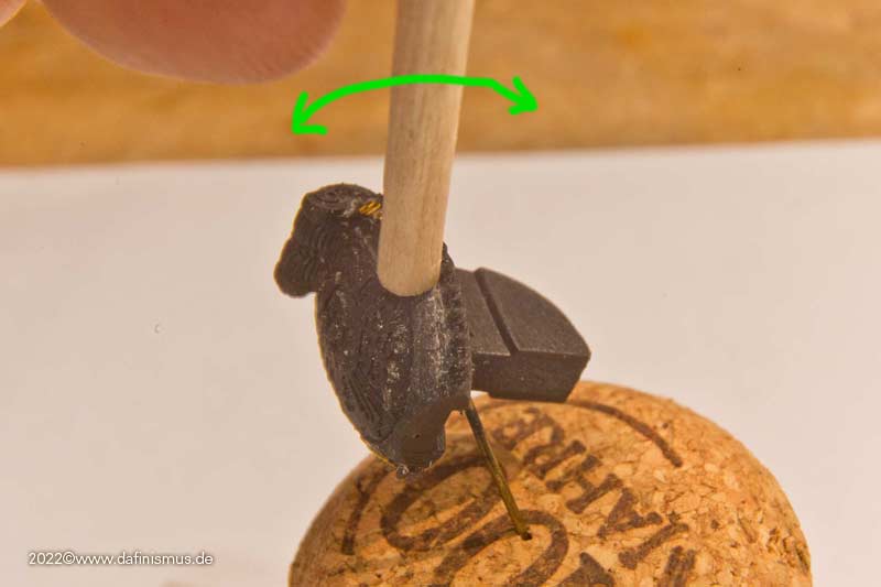
... ... and with a thicker chopstick pressed the letter to the curve by tilting it in and out.
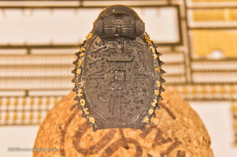
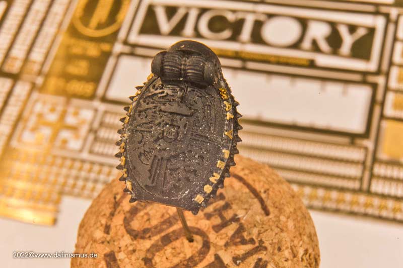
Here's one with the letters imprinted ...
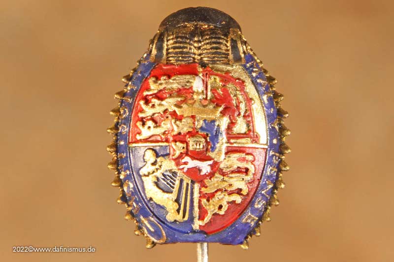
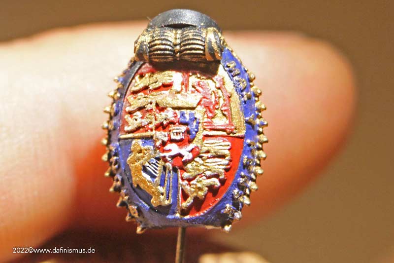
... and once with etched parts glued on.
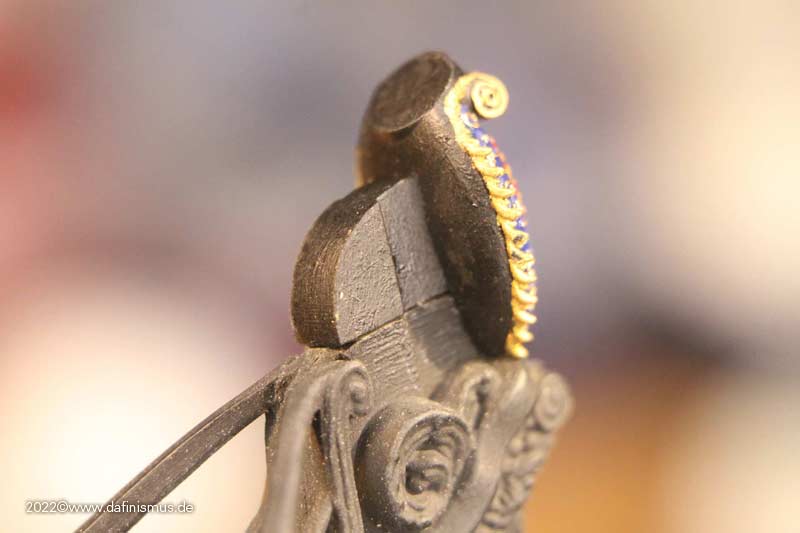
The back also finally has volume and sits neatly on the head.
And for the sake of completeness here the comparison to Heller's original part, the painted one finally slightly inked to get the necessary depth.
Dear greetings and a happy new year to you all, Daniel


HMS Victory by Twahl - Heller - 1/100 - PLASTIC
in - Kit build logs for subjects built from 1751 - 1800
Posted
Wonderfully done! Thanx for showing.
All the ebst, DAniel