


dafi
-
Posts
2,284 -
Joined
-
Last visited
Content Type
Profiles
Forums
Gallery
Events
Posts posted by dafi
-
-
In between all the X-Mess preparations, I actually managed to get down to business again http://www.shipmodels.info/mws_forum/images/smilies/icon_smile.gif
Status:
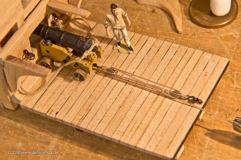
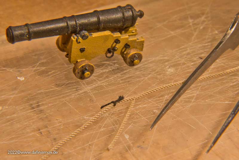
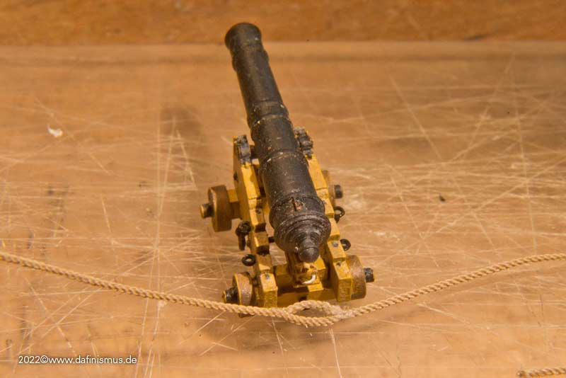
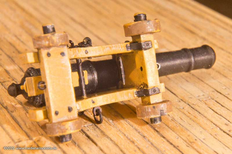
First it was about taking the measurements.
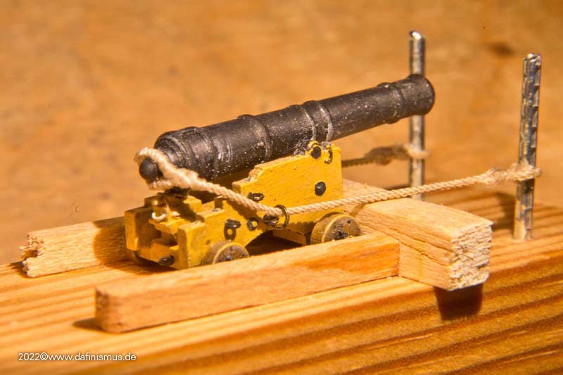
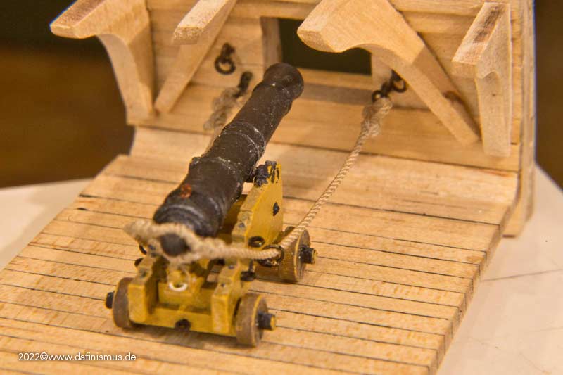
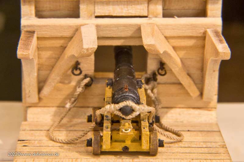
That means at the back the blocks must not overlap ...
... and the front position determines the length of the lanyard
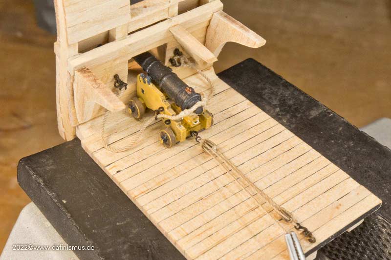
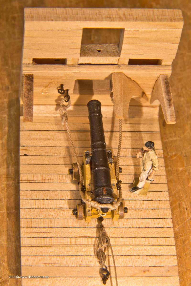
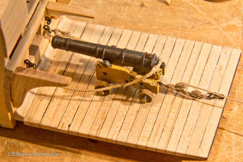
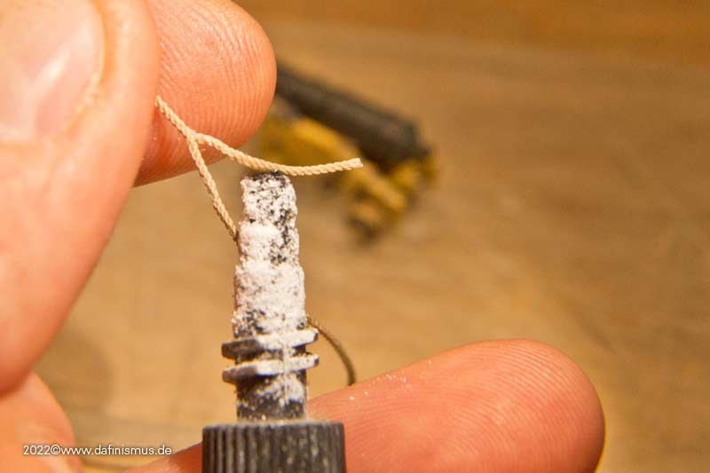
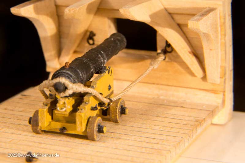
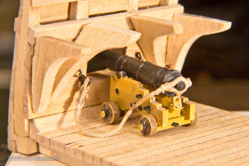
And always the anxious question about the side rigging. After the shot in the retracted position and enough rope for 3 to 5 men to pull, yes there is quite a bit of rope left when the piece is run out again.
But if no one pulls the ropes, it isd mostely displayed directly as running into coils lying on the deck. That has two flaws: First, so the gun can move by itself and slide inward. In addition, the rope is shown mostly in a stretched position that would never be able to run smoothly into the coils, as it obeys gravity that pulls it.
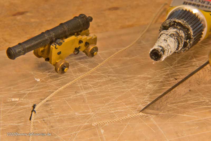
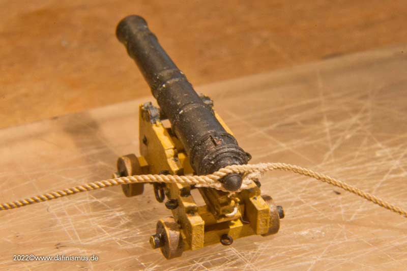
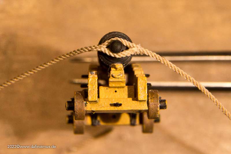
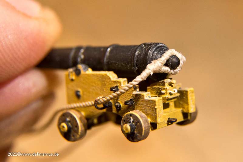
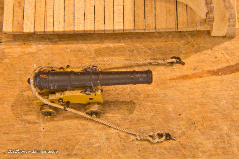
So if no sailor is at hand and secures the free ends, the rope should be secured to the gun, the tackle or the ship's side. On my Vic I had made a half hitch around the aft end of the side tackles, Boudriot shows the "amarage simple" around the cascable. The first attempt went wrong, as at Boudriot there was no splice over the cascable as the breechline goes through the gun carriage, and there it worked well. After some research I found a reference, where the lanyard was led under the eye splice of the breech.
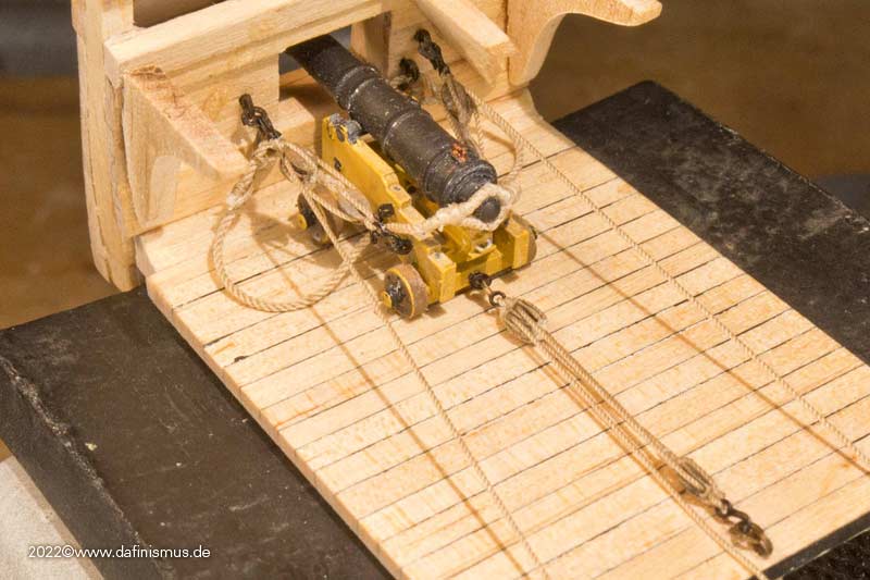
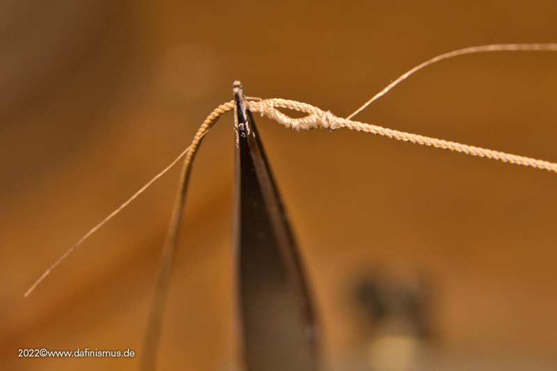
So the free end around the cascable, some turns as required ...
 as
as
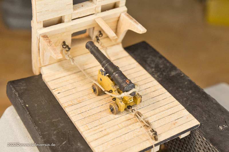
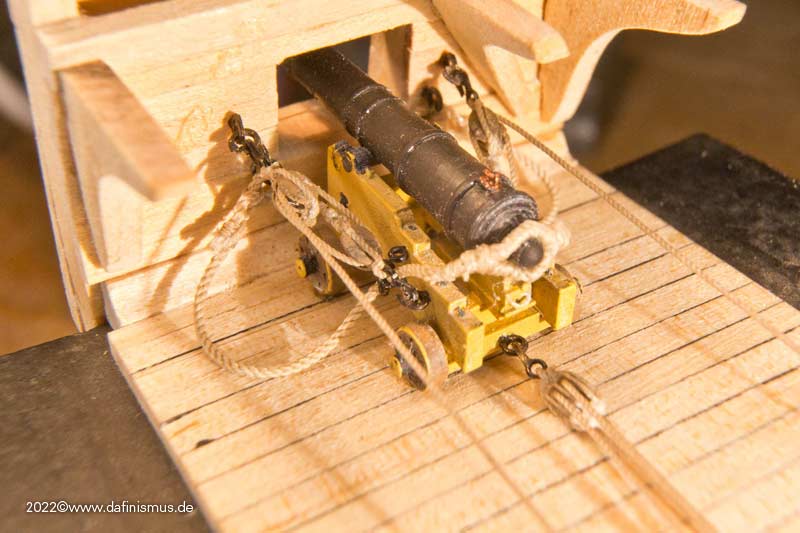
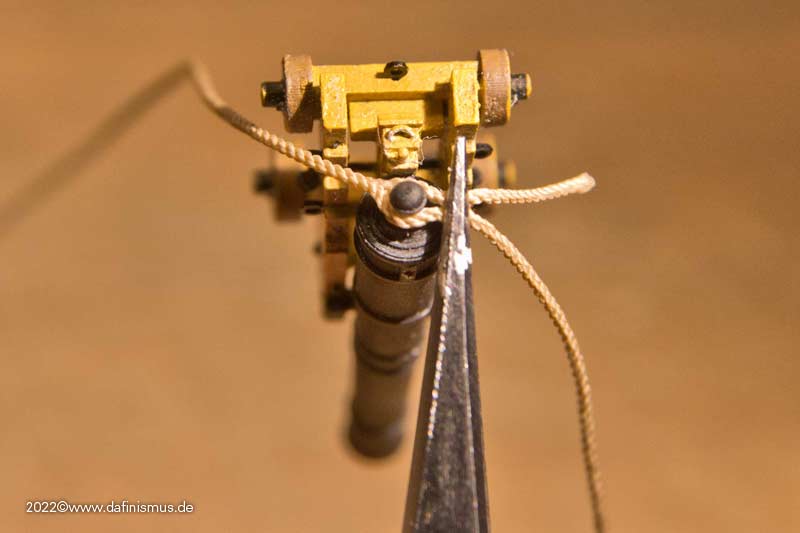
... and the rest as a bunch neatly arranged on one of the hooks.
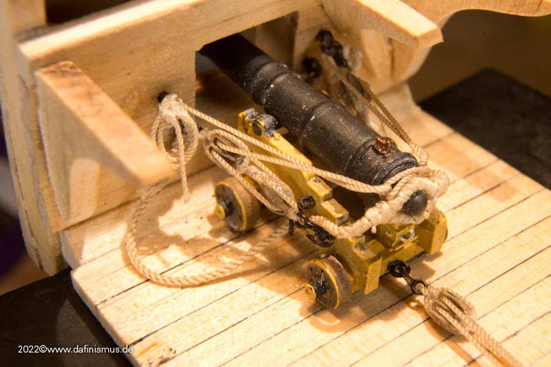
So everything should be neatly tidied up and secured.
XXXDAn- Morgan, T. Alex, mort stoll and 3 others
-
 6
6
-
Until now, the bottleneck in rigging the guns were the blocks: There were almost no small ones, and if there were, they were often difficult in appearance or quality.
Recently, I have test rigged my smallest self-printed blocks times and noticed that fine thin and steady surgeon hands are needed, including good visual reinforcements.And I realized that suddenly it is now me beeing the bottleneck ...
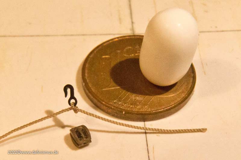
Here the measure of things was the thinnest rope I needed in 1:100, 0.2 mm diameter. Something for the filigran ones among us http://www.shipmodels.info/mws_forum/images/smilies/icon_smile.gif
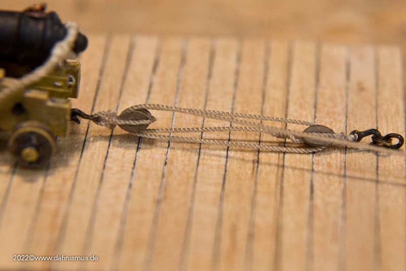
Now the pragmatist in me came out again. According to the old literature I need for the guns in 1:100 / 1:98 the diameter off 0,3- 0,4 mm for the ropes for the lanjards of the side- and back tackles. The 0.4 mm rope is also a common thickness for Gondesen and other suppliers in the aftermarket. So a block combination on this rope thickness is required, and also a good method in which this is done quickly and with good visual results.
It has cost me a few attempts, meanwhile I have found the right variant for myself.
First a normal classical knot to tie the hook in ...
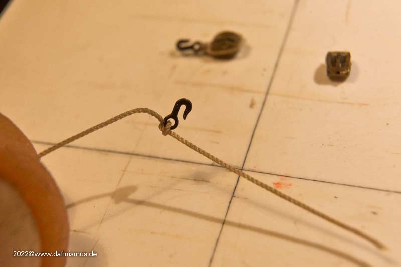
... then the whole thing tightened to the back, in order to make the hook sit well in the middle ...
... spreading the ends again and ...
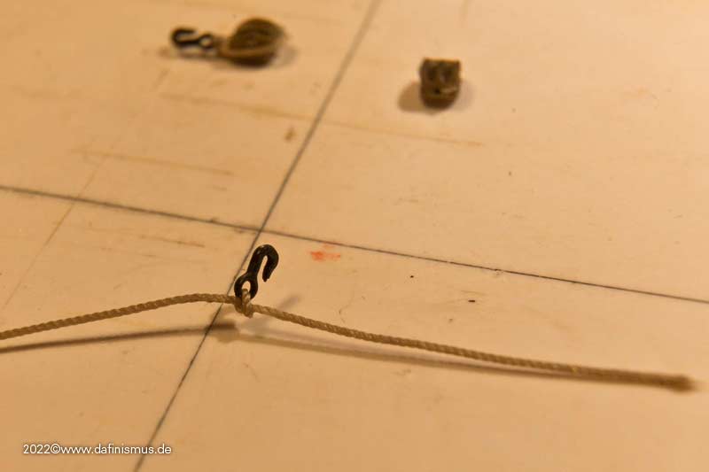
... put the block of choice ready.
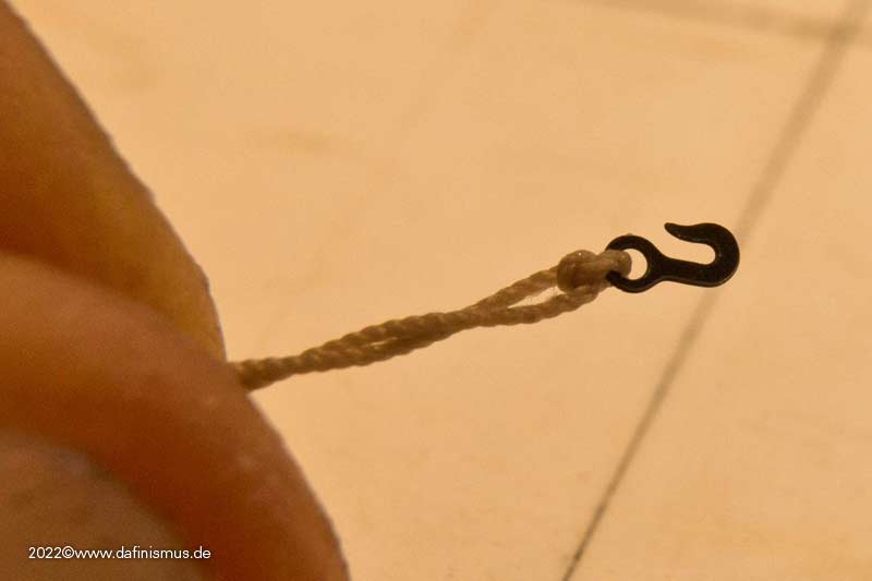
Then clamped the hook between my fingers, used a toothpick to make a drop of super glue in the middle on the knot of the hook and centered the block on it.
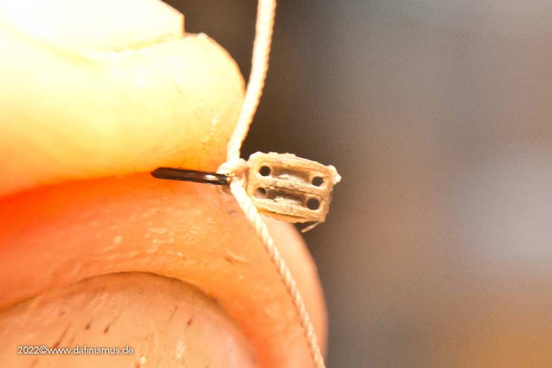
Don't let go of the hook now, but detached it would look like this.
This is just the positioning guide to superglue the groove on the side with the toothpick on one side and pull the rope well over it.
Do not grab the glued area, but pull on the free end. This works quite well without the whole thing forming an inseparable bond with the builder.
Then glue the groove on the other side, pull the rope over it accordingly and make sure that the pull is even and the hook hangs centrally over the block.

Then glue the bottom of the block with the toothpick and pull the ends against each other, cut off the excess diagonally, and press the two slanted ends against each other with tweezers or pliers, securing again with glue if necessary.
And then you already have it in your hand, the rigged double block http://www.shipmodels.info/mws_forum/images/smilies/icon_smile.gif
If you want you can strop the bridge between hook block a little bit, but I noticed that it doesn't help that much, so I made it easy for myself here.
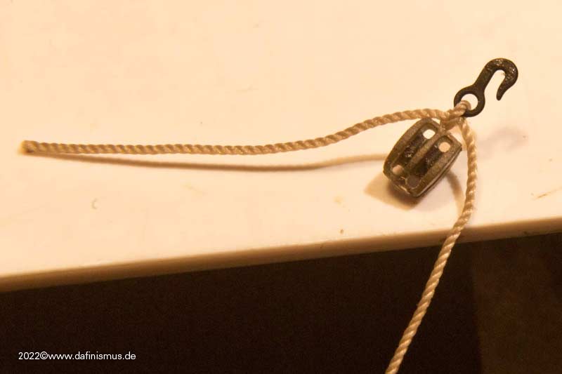
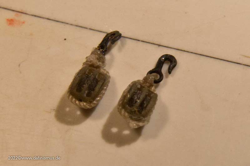
By the way, here is my first attempt, you can still see it somehow crooked, and the one after that, you can see, practice makes perfect http://www.shipmodels.info/mws_forum/images/smilies/icon_wink.gif
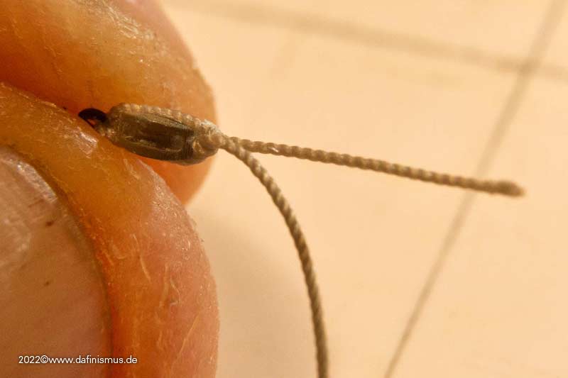
With the single block it is the same, thread hook on the rope, knot, pull back, spread, hook between the fingers, glue in the middle, block on it to secure, glue the side and pull rope over it, glue the other side and pull over it, and now the difference, on the bottom a knot and secured with glue.
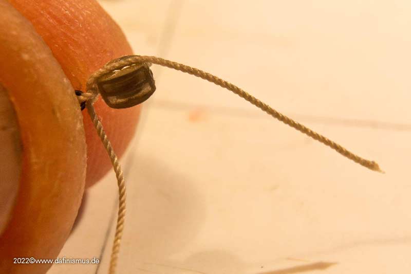
Then the free end stropped up, glued and cut tight ...
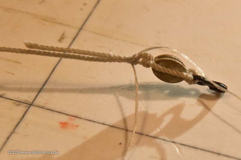
... and the pair of block is ready http://www.shipmodels.info/mws_forum/images/smilies/icon_smile.gif
And the other two pairs came together quite quickly, so I soon had a set of three ready for my gun setup.
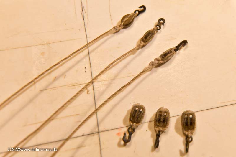
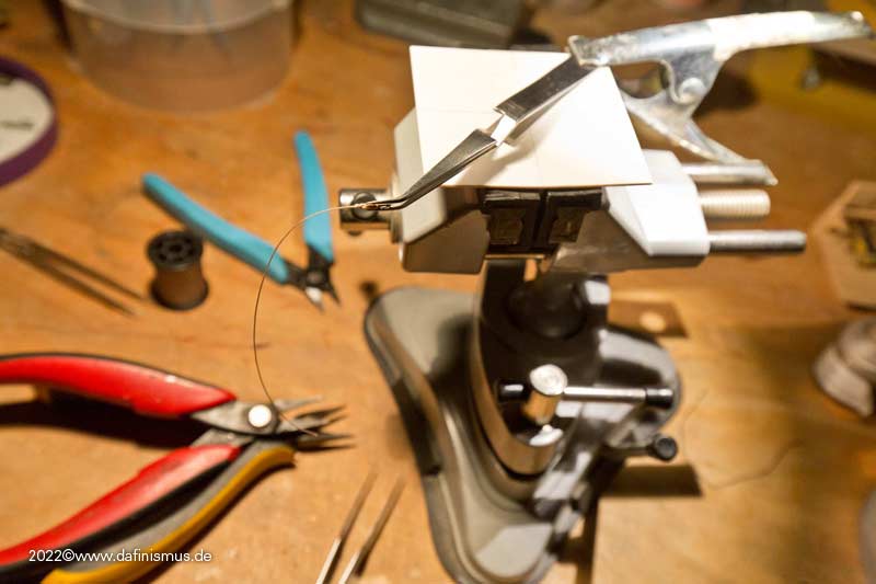
And as I said, no other tools or jigs were needed than a toothpick as a super glue applicator, I only used a pair of self-clamping tweezers on my bench vice to srop on the free end of the single block.
All the best, DAniel -
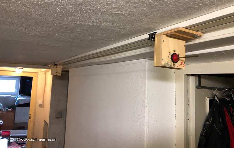
Finally after a long time remounted my rope walk again. For space reasons simply hung in the basement hallway under the ceiling :-)
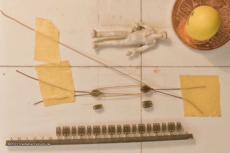
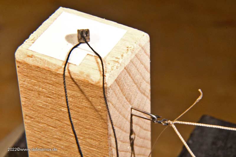
Then I started rigging to try out the blocks. In the contemporary plans, the blocks are about half the width of the forward wheel. These blocks are minimally larger, which makes handling much easier. To do this, nailed a mounting hook into a piece of wood for holding the hooks. And for that the small blocks do not go off, I always put them immediately on the leash 🙂
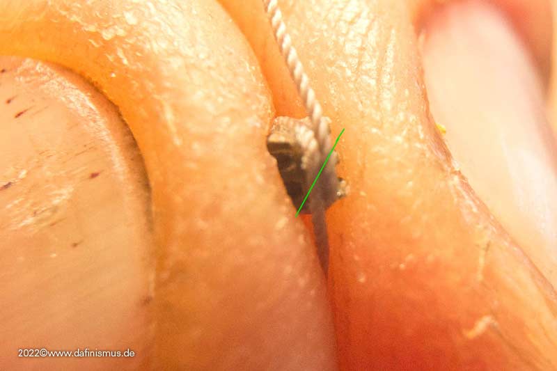
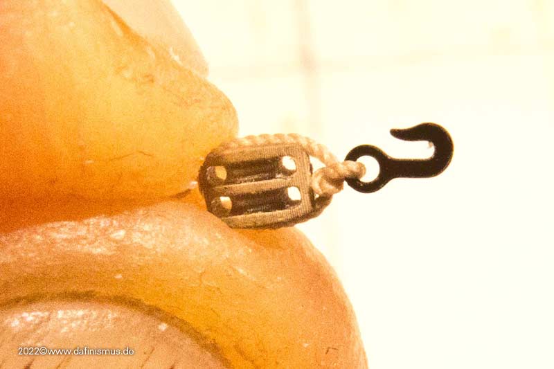
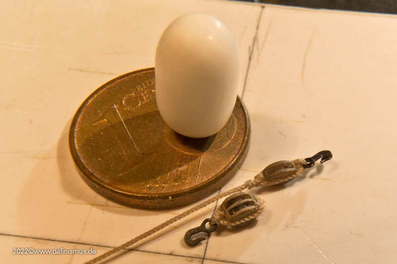
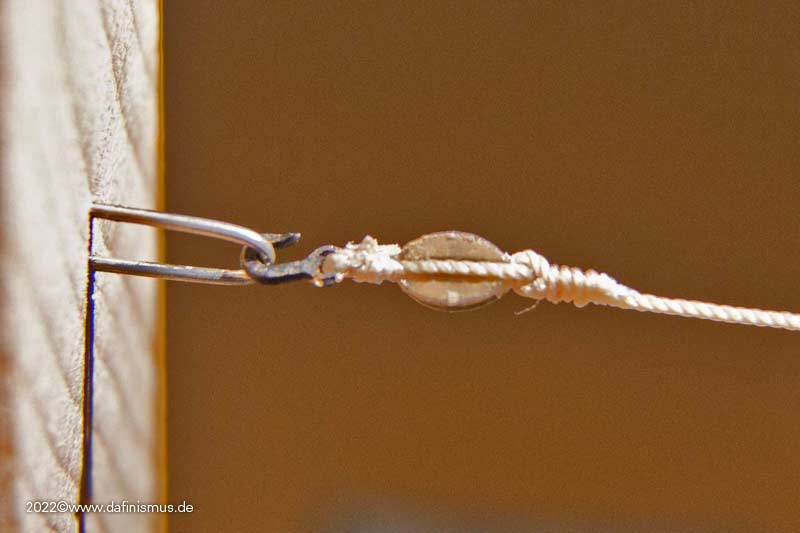
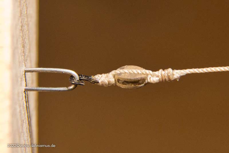
And here the rigged hook and block from close up.
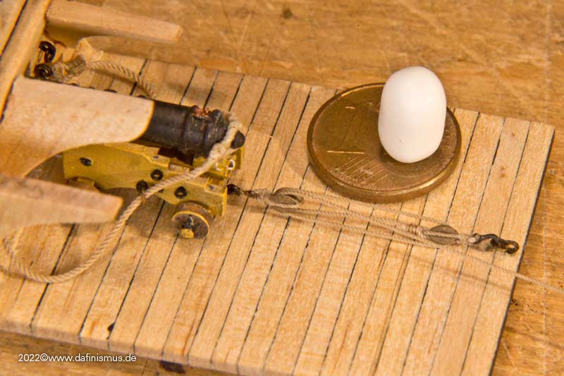
For comparison in size ...
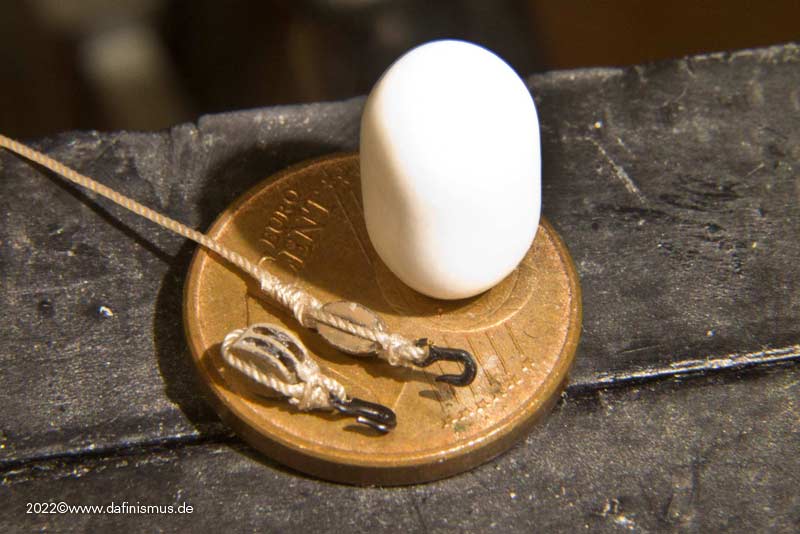
... and in place.
Since I had pulled down one of the knees with my thick sausage fingers, I immediately took the chance to be able to photograph undisturbed 🙂
Greetings, Daniel- popeye2sea, Prowler901, rybakov and 2 others
-
4
-
 1
1
-
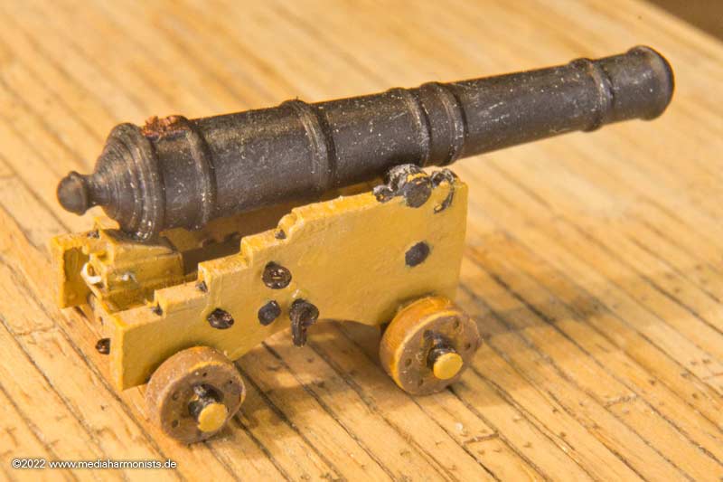
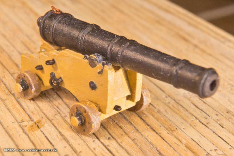
I continued a bit over the weekend.
First fixed the bolts and rings in the hull ...
Then prepared the breech: 0.6 mm, the middle marked by means of black thread. The barrels had no brech ring on the pommelion, so the breech needs an eye splice to prevent it from slipping off. The small parallel piece is glued on first. So that the attachment is not too obvious, it is cut off at an pointed angle ...
... and glued on.
Then came a test fit to determine the length.
Stabilized the cut with super glue ...
... glued on ...
... and fits http://www.shipmodels.info/mws_forum/images/smilies/icon_smile.gif
A good model building solution in itself, ...
... but in the original, this splice was additionally dressed to protect against the large stress when guns were fired.
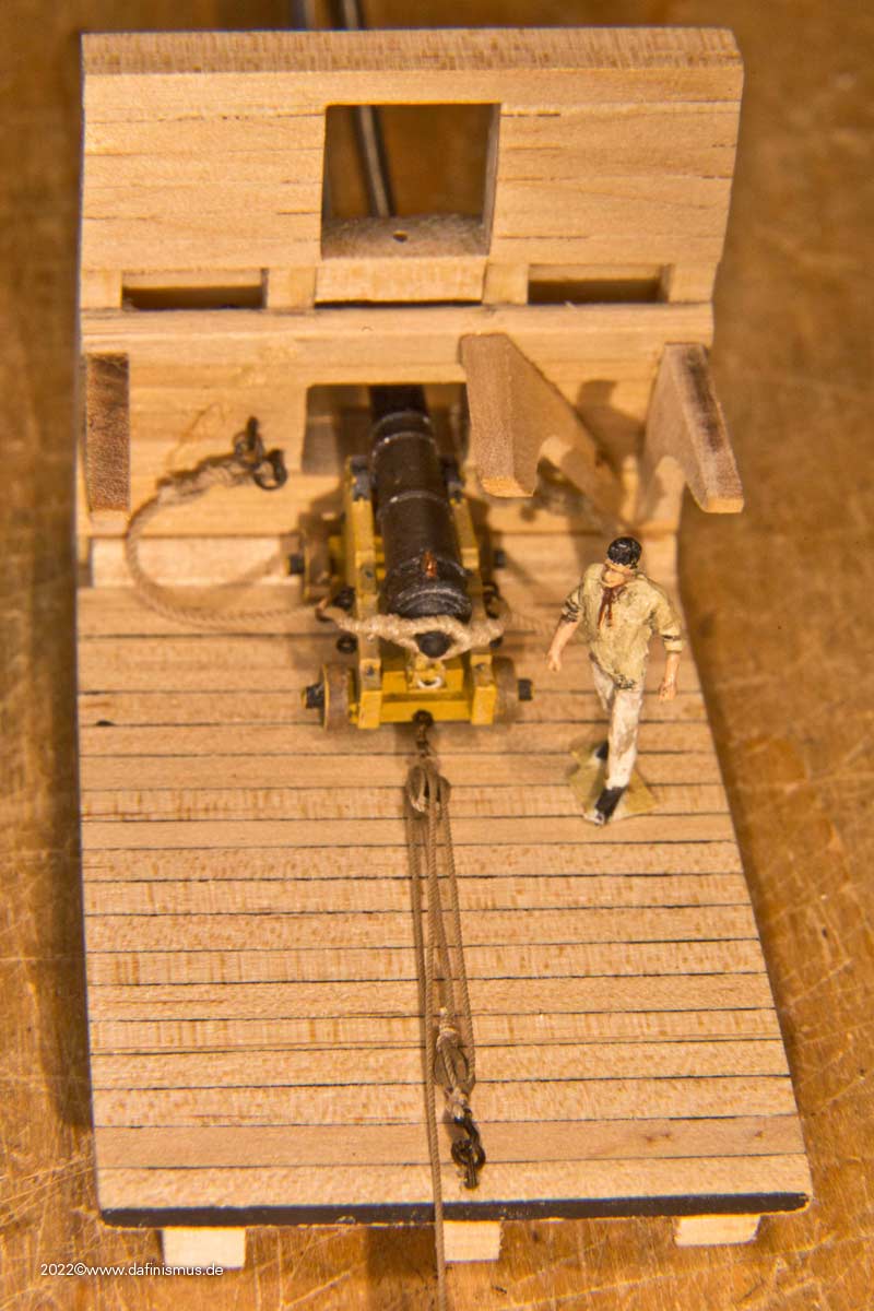
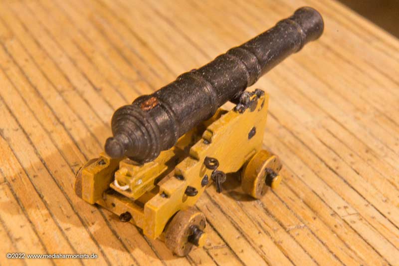
Then made a template for the length of the breechline. The eyes are bound in the manner of the dead eyes.
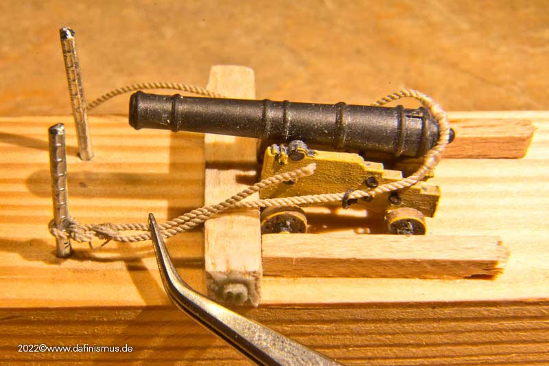
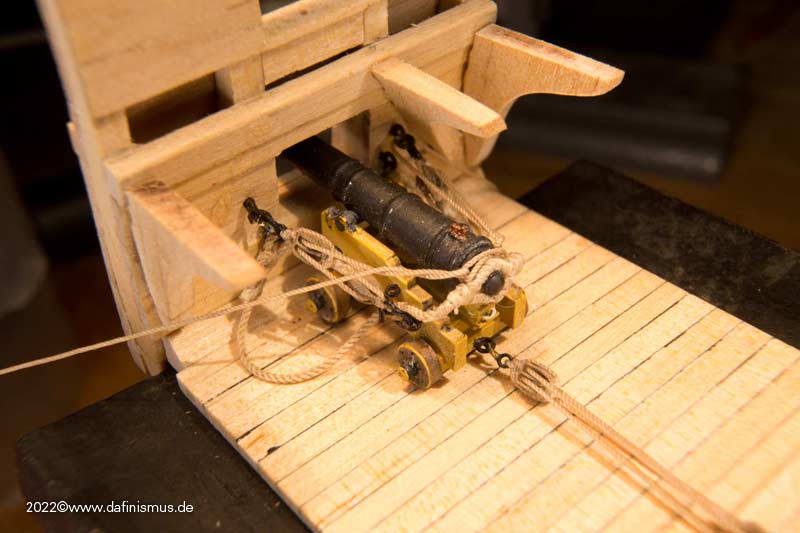
And everything is ready for installation ...
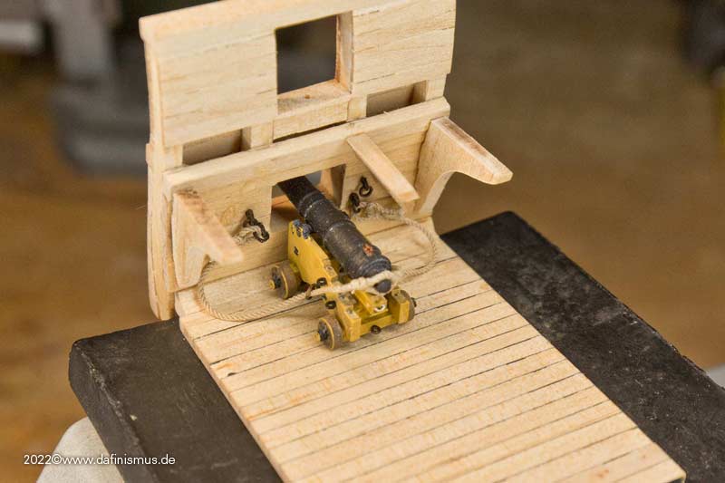
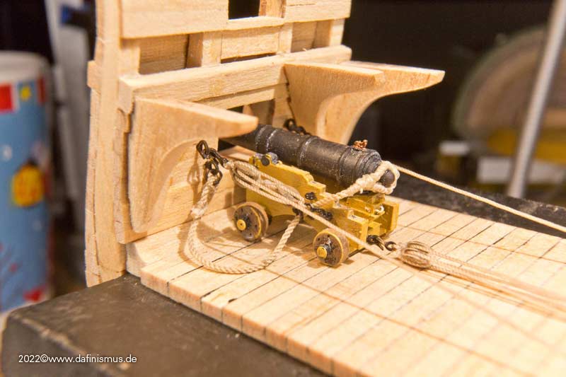
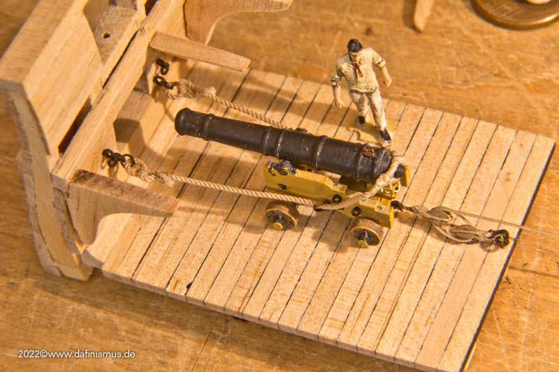
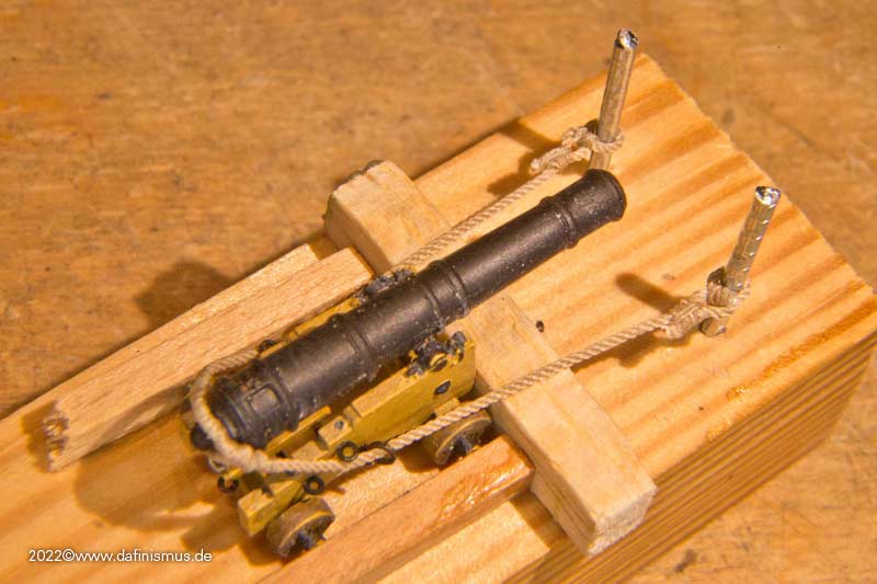
... and in place. Here in the loading position at the very back, the brooktau tensioned.
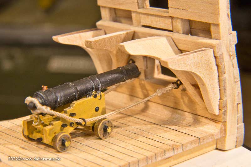
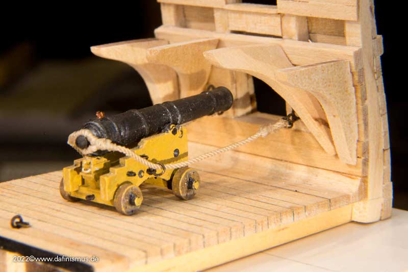
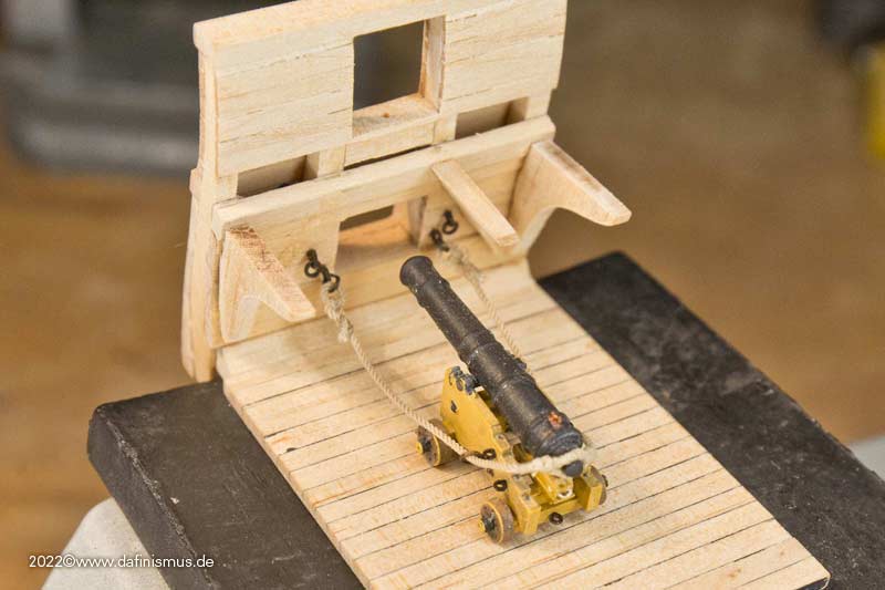
And run out here.
So slowly it's moving in the right direction.
XXXDAn- mort stoll, rybakov, Prowler901 and 2 others
-
5
-
Oh my favourite topic 🙂
I am having a good collection of the topic at https://www.segelschiffsmodellbau.com/t866f104-The-Heads.html
One can activate the automatic translater if you scroll down the page and on the bottom you will find a button with "Sprache auswählen". Change this to english or the language that you prefer 🙂
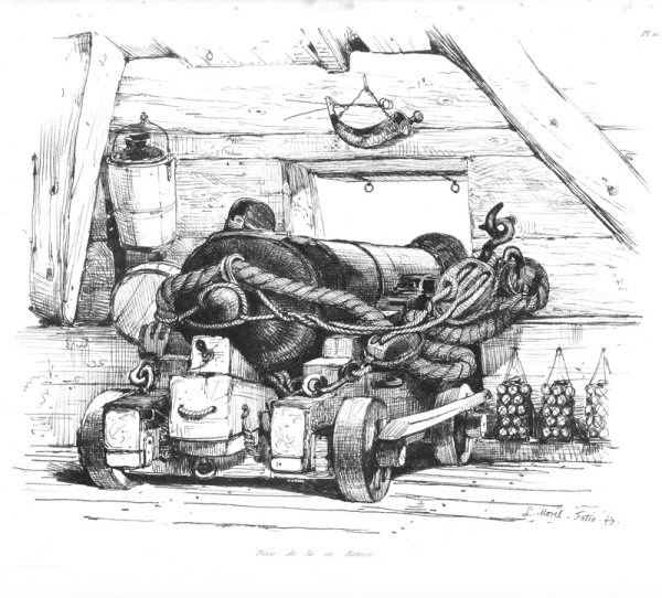
Especially I like the contempoary grafics and paintings, even two lads doing business in the middle of a raging battle ...
:-0
XXXDAn
- Canute, thibaultron and bruce d
-
1
-
 2
2
-
-
On 10/27/2022 at 12:56 PM, dafi said:
... More intriguing in your picture is the use of a cablet as breeching line.
Just realised, that todays Constitution has cablets as breeching lines. Surprising, as they are meant to be more stiff than normal right handed lay, therfor more danger of breaking under the violent bent at the breech. Par opposite the Victory has (or at least had for a long time) lefthanded breeching lines, probabely as they are more flexible, means less breakable and also better absorbing the shocks. Any Idea of that?
XXXDAn
-
On 9/21/2021 at 5:24 PM, allanyed said:
I just noticed something on the painting I posted above which gives me pause. There is a double block hooked to the carriage which means there is a double block at the bulkhead as well, but even then it appears that the line starts at the double on the carriage. This would have the loose end coming from this block which would be in the wrong direction. From everything I have found to date, there were never two double blocks, even on 32's which were the largest guns on Victory. So much for accuracy on this painting (which was done quite a few years after Trafalgar)
Just realised on a picture I posted in the Gibraltar thread, that there too were double blocks hooked in the back of the carriage. Here clearly the standing part comes from the other hook. More intriguing in your picture is the use of a cablet as breeching line.

- mtaylor and Charles Green
-
2
-
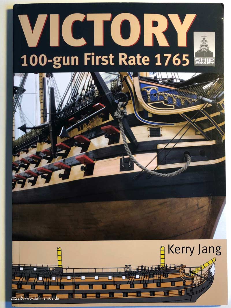
I got mail today, fresh off the press, from Kerry Jang in Canada:
Victory, 100-gun First Rtae 1765, Seaforth Publishing.
The book is part of a series ShipCraft and is number 29.
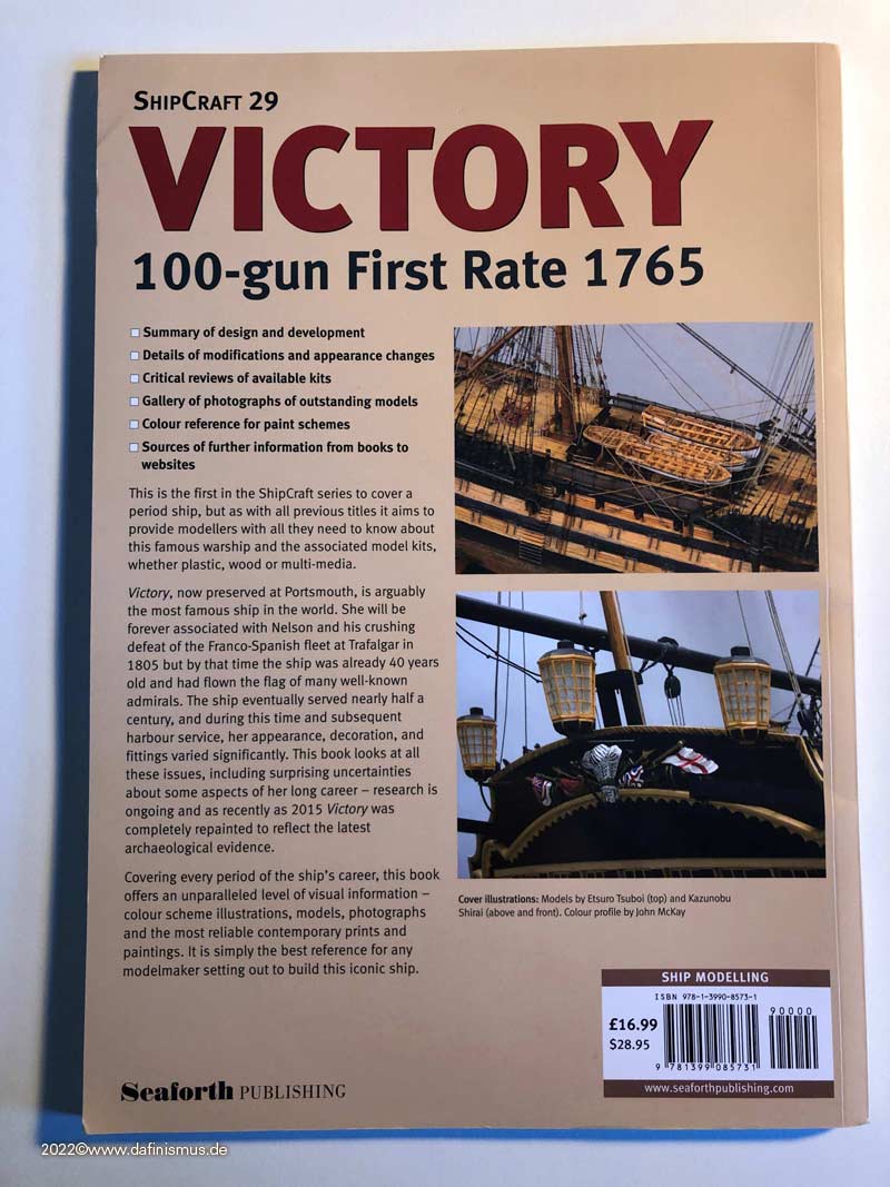
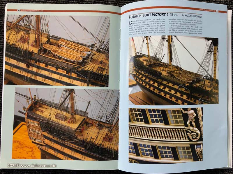
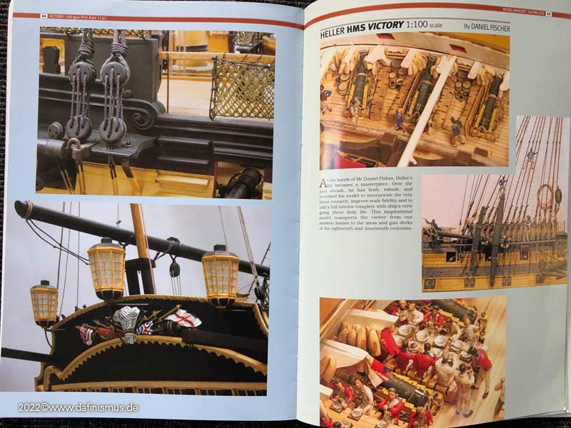
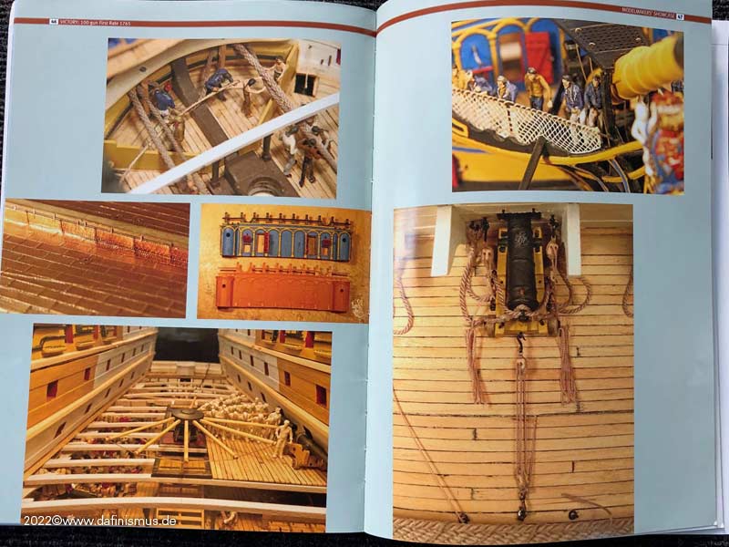
The book deals with Victory model kits and is aimed specifically at modelers. Besides history, it presents the available kits from 1:1200 to 1:64 in the full range of materials, gives an overview of the current aftermarket and presents 3 built models. A larger article goes over the various appearances of the ship and ends in new overview drawings, done especially for this book by McKay.
I have yet to analyze the historical and appearance part at times, but know that Kerry Jang has talked to a great many protagonists of the Victory scene.
Personal notes:
- McKay´s AOTS was my first stop on the way to Victory. The color on the book´s pages were watched pale ever since.
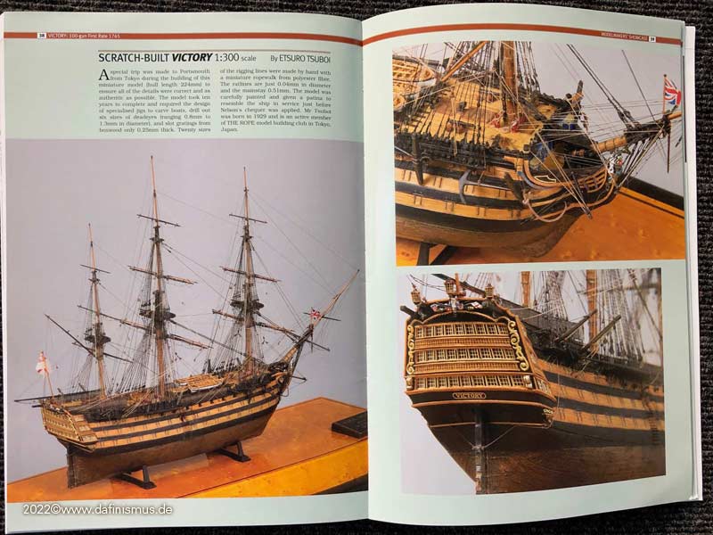
- I stood in front of the first of the 3 models presented in the book at the convention in Rochefort with my mouth open, jaw to the floor: the 1:300 version by Etsuro Tsuboi. Breathtaking!
- The second model of the Victory is 1:48 by Kazunobu Shirai and it was the first model of this ship that I fell in love with over 15 years ago when I started doing internet research on this ship.
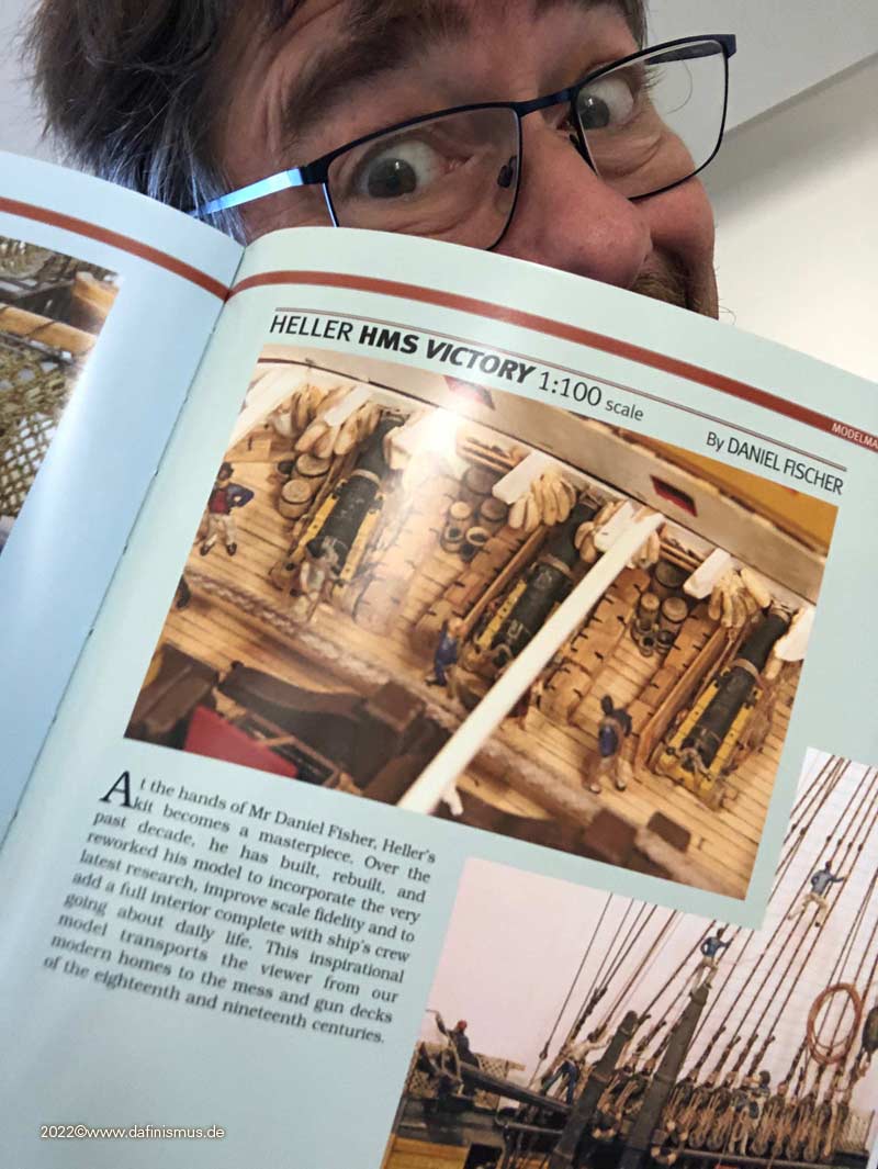
- And the third model shown is actually the little fatty one with bumble bee stripes by a certain dafi :-0
Never, really never would I have dared to dream of ending up with 3 of my heroes in the same book!
Thank you Kerry for that opportunity!
Dear greetings, DAniel
-
18 hours ago, Bill97 said:
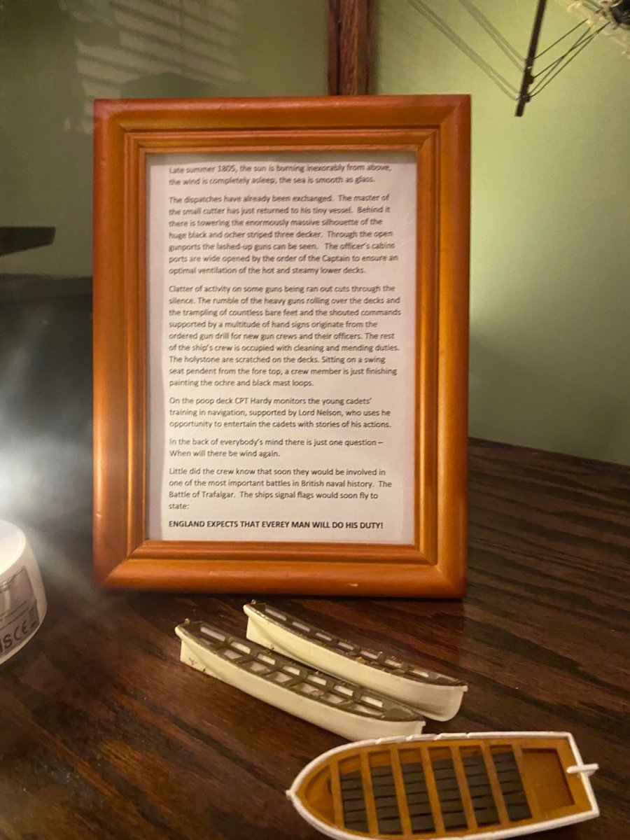
... Daniel I hope you don’t mind but I used part of your text on the first page of your build. Late summer 1805….. for the the little sign I included. ...
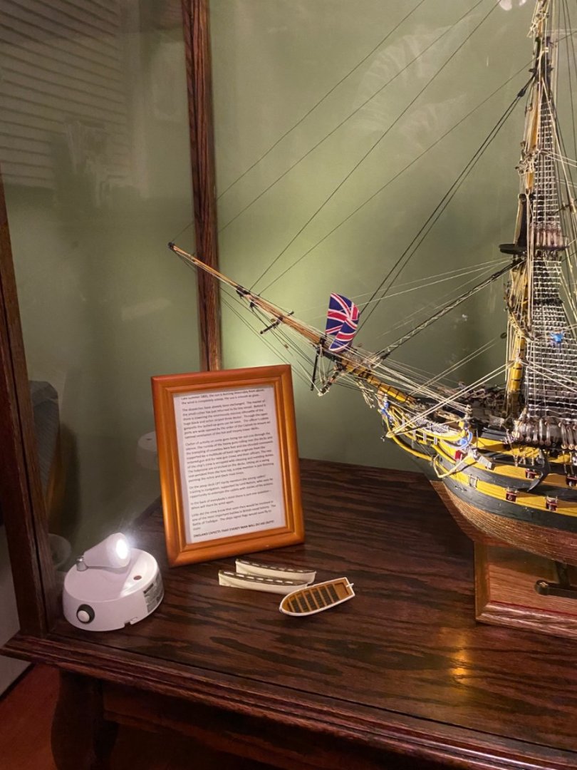

Dear Bill,
it is a great honor and splendid pleasure to be quoted by you in such a wonderful display with this wonderful rendition of this iconic ship! It had become an icon in its own sense. Wonderful model making, and congratulations, far too many good model makers never brought it that far in that perfection!
All the best, DAniel
-
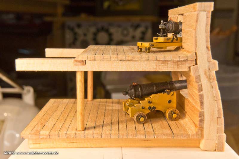
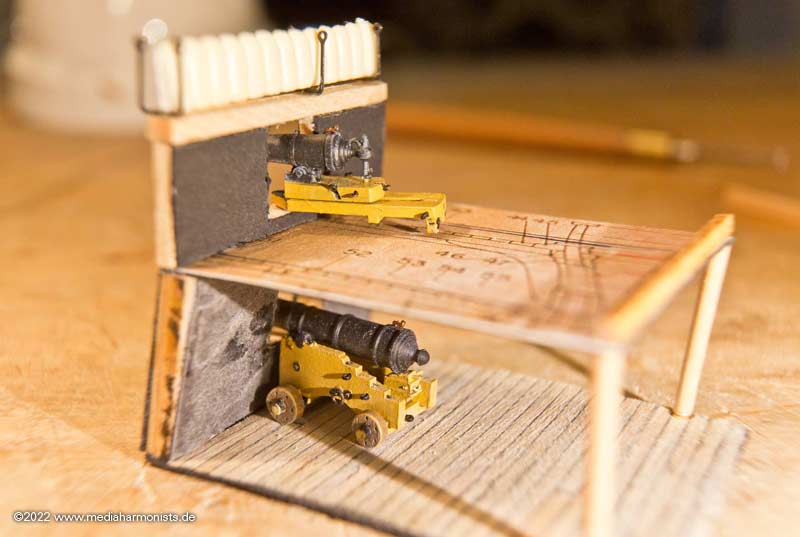
And I was finally able to do some more woodwork. Got the lathe out and turned some supports.
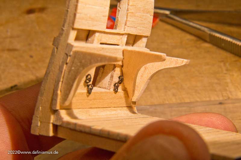
Then built the 4 knees. And suddenly the part flew towards the aspiration tube. THAT'S WHY I have the perforated metal grating there on the smoke http://www.shipmodels.info/mws_forum/images/smilies/icon_smile.gif
Fitting ...
... and ready.
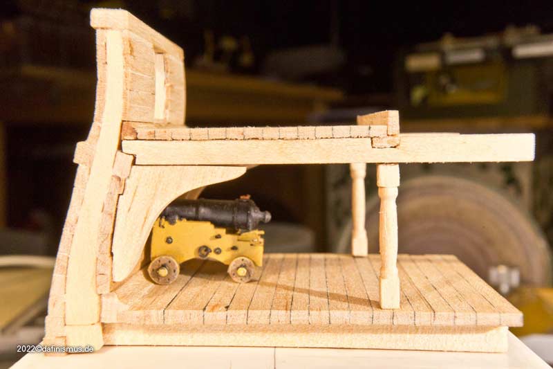
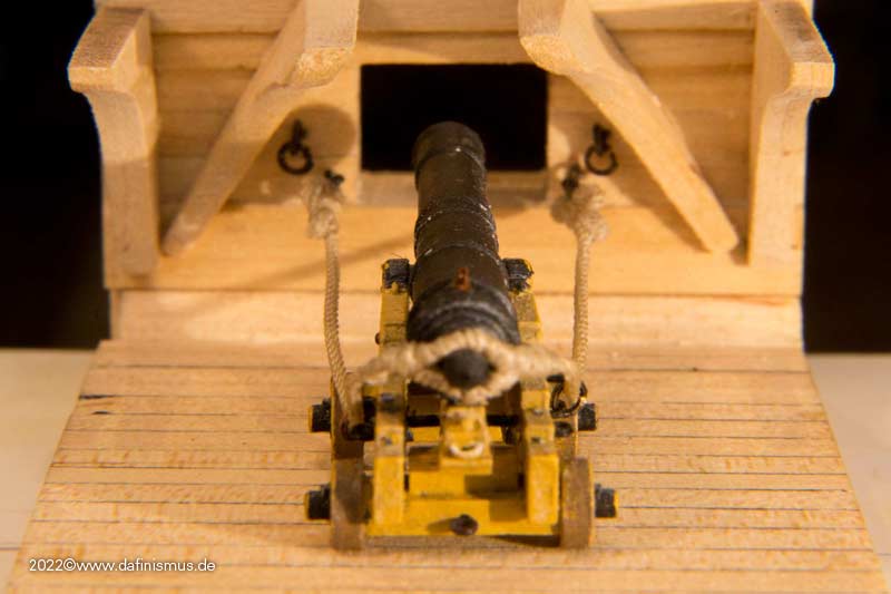
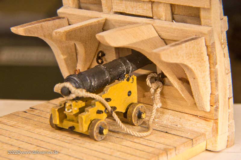
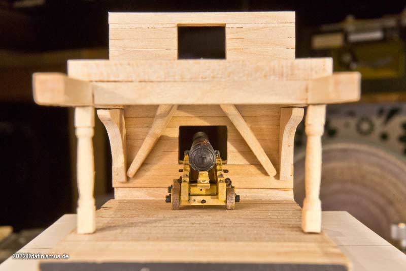
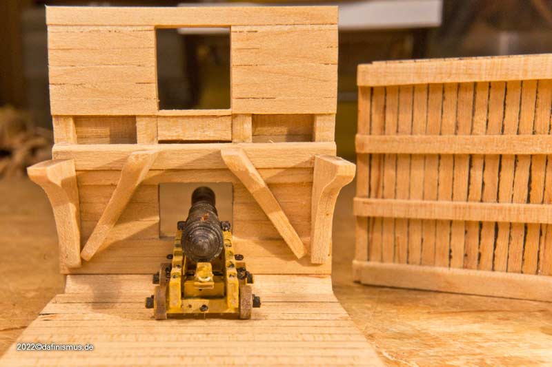
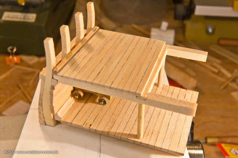
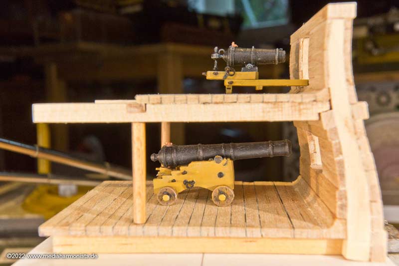
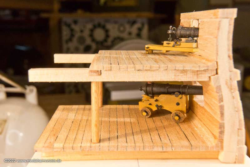
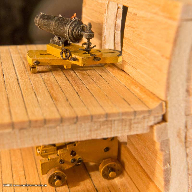
Here you can see the two diagonal knees above the gun.
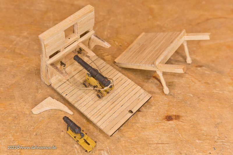
And so that I don't mess up when rigging the gun tackles, I made the upper deck removable.
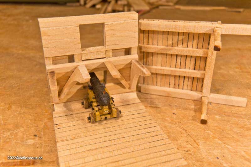
Now it's going to be small itsbits, looking forward to it,
XXXDAn -
-
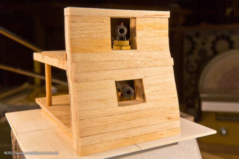
Possibly something alike like this russian position at the Crimian War. Shelter against sharp shooters and shrapnels.
XXXDAn
- Belco, tkay11, Keith Black and 1 other
-
4
-
There are several contemporary models showing this feature in the NMM archives. Many of them still have a large compass rose in the middle. If I remember well, there is already a thread here in MSW showing those.
https://collections.rmg.co.uk/collections/objects/549999.html
SLR0506.3; 'Superb' (1760) Date made circa 1760

Also a nice detail about Nelson, reported by his secretairy: As he did not want help to dress and undress as for his missing arm, he always wore loafers even at heavy weather. So he was able to dress and undress them by himself and if his feet got wet he used to walk in socks over the carpets in his cabin, until the feet got dry 🙂
This means, it was not unusual to put something over the chequers still.
XXXDAn
-
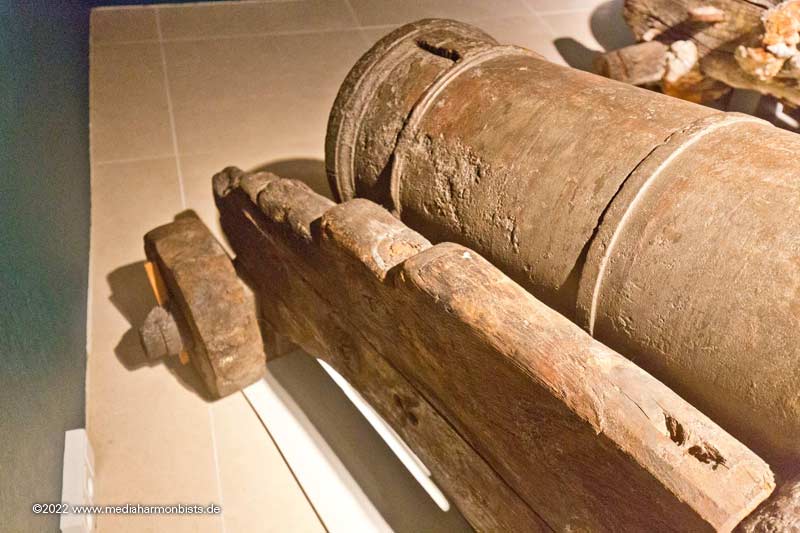
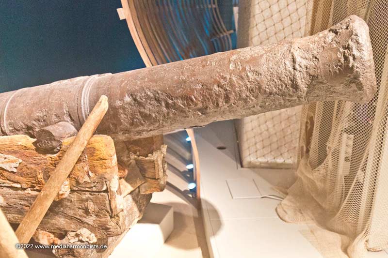
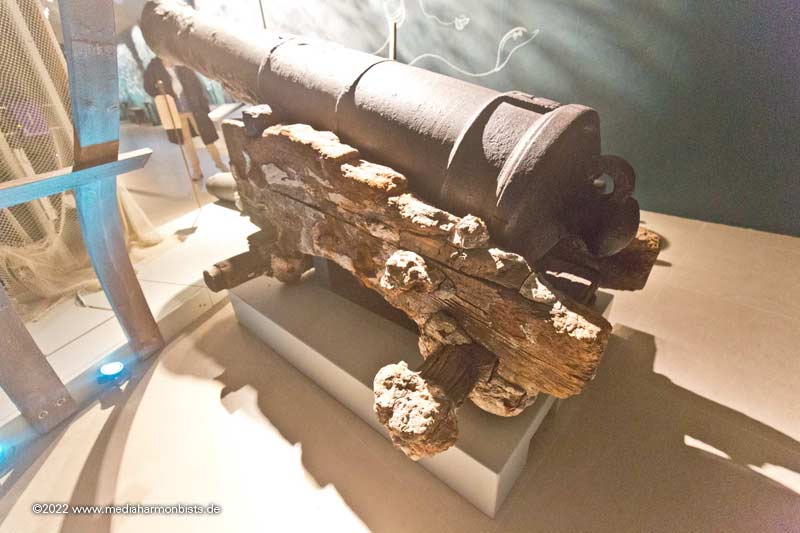
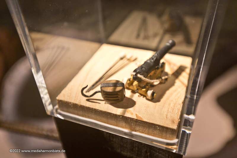
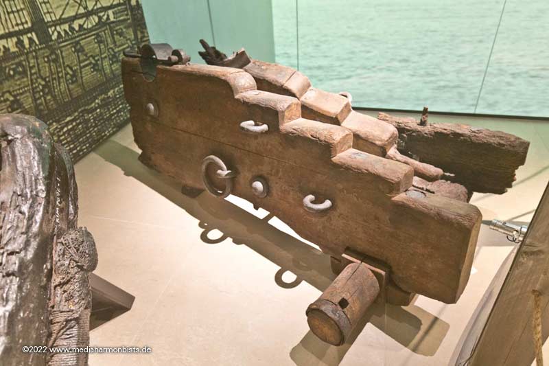
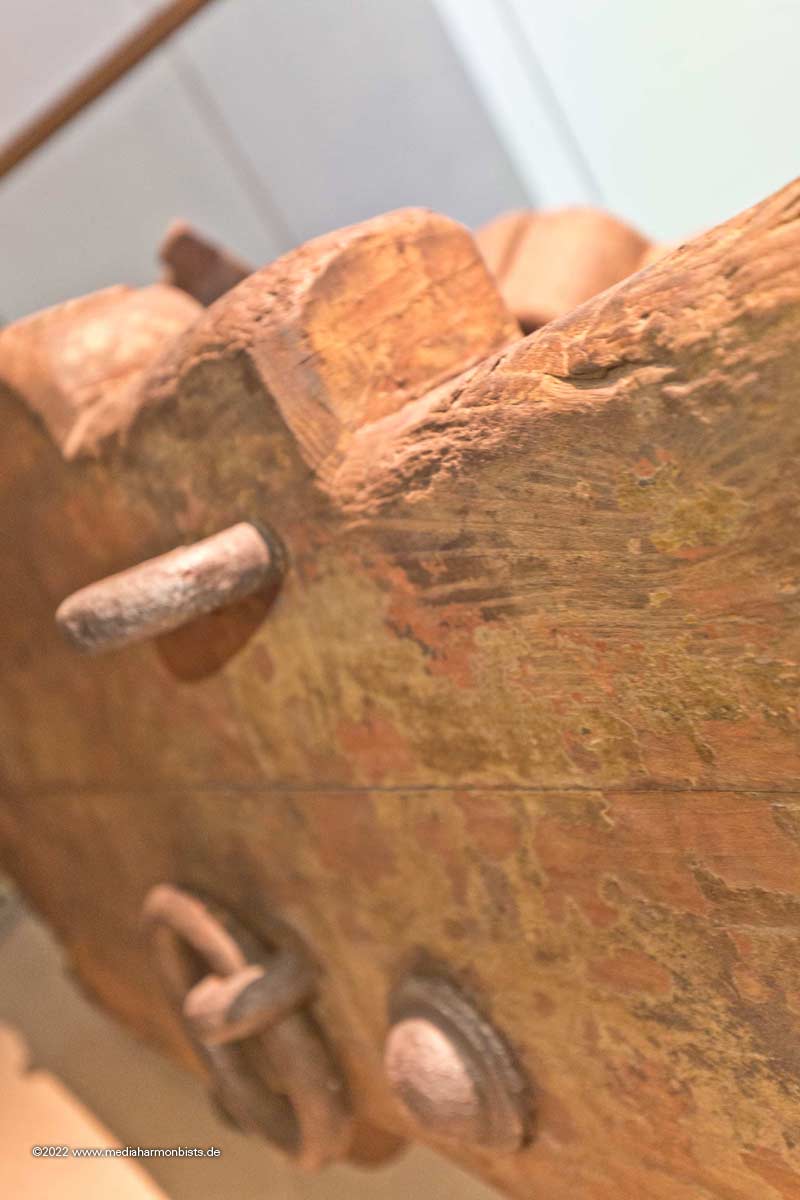
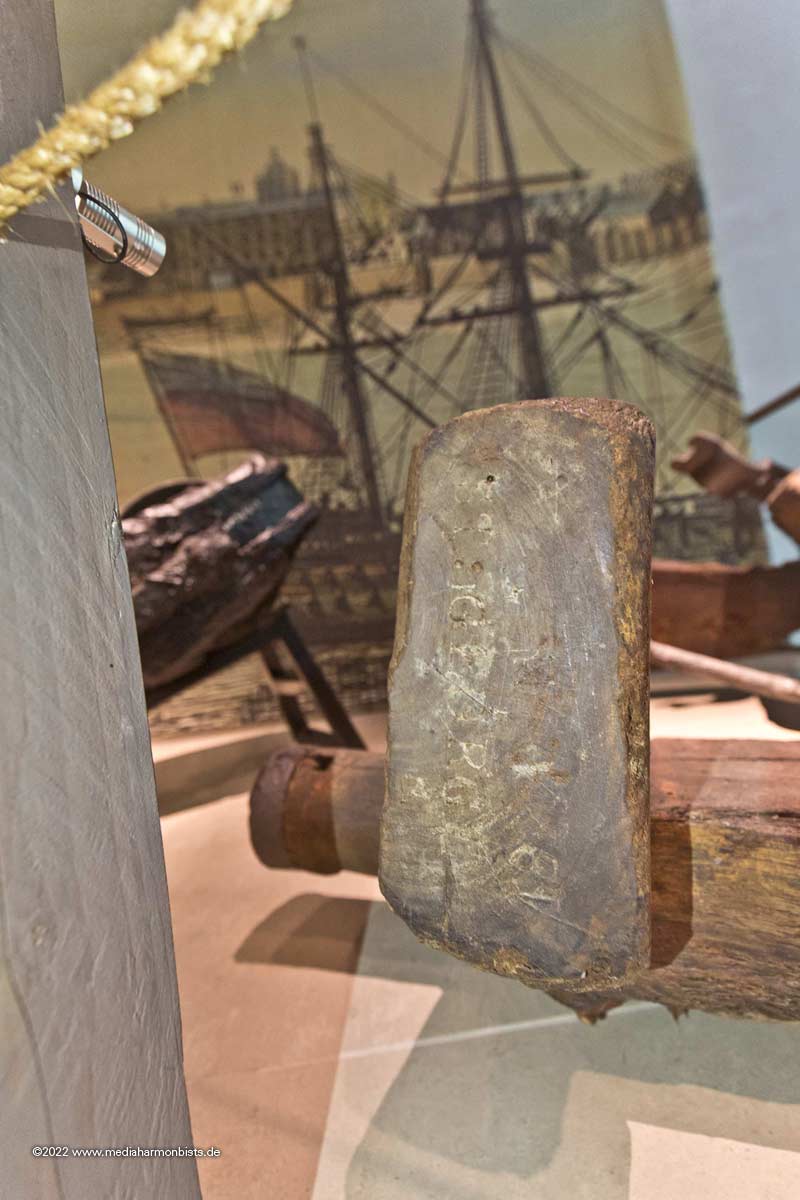
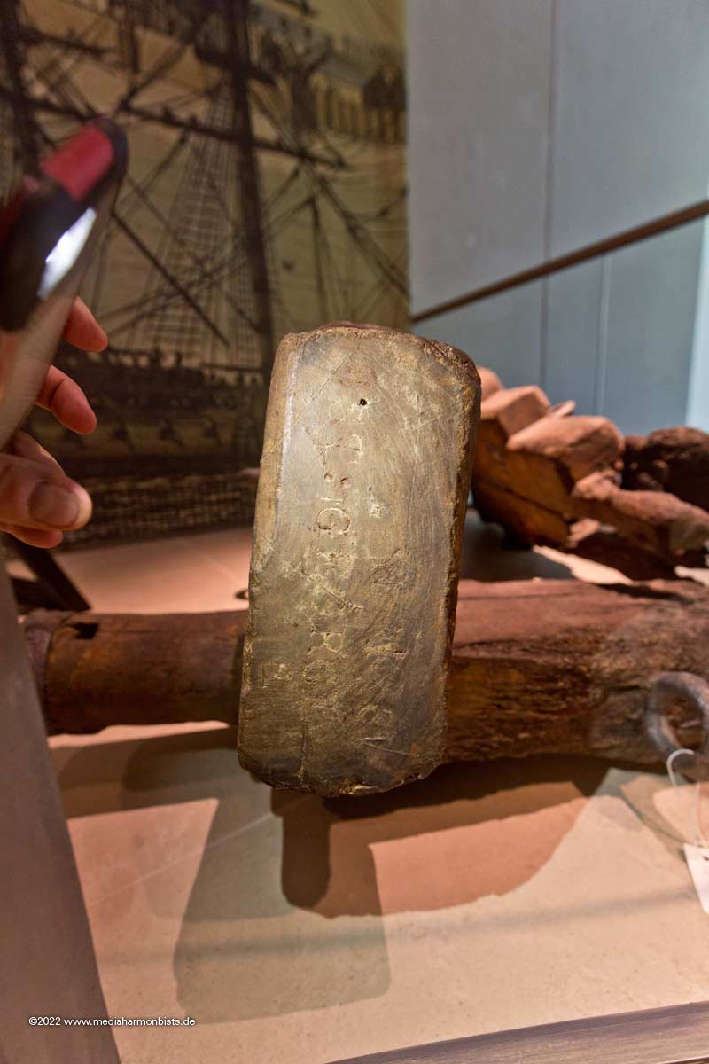
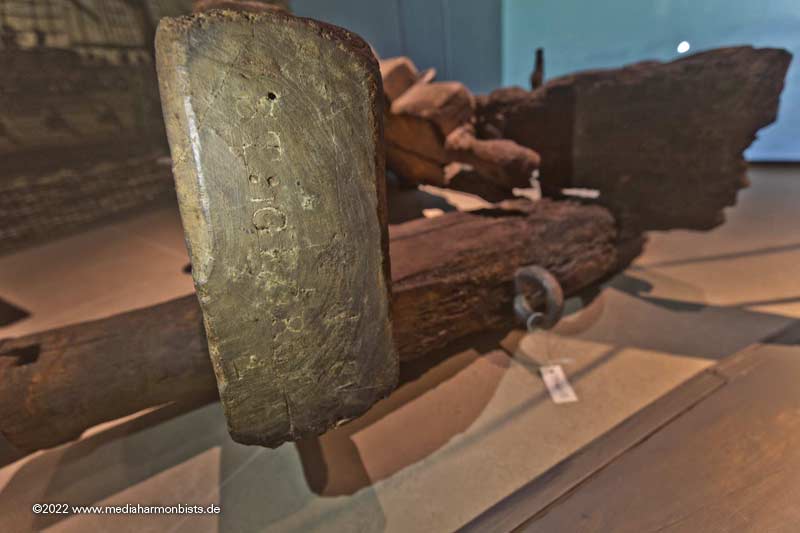
As this topic came up newly, I can add some better pictures of Thorsminde, taken this summer :-)
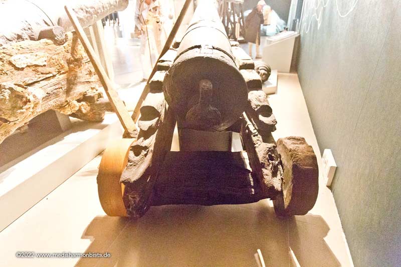
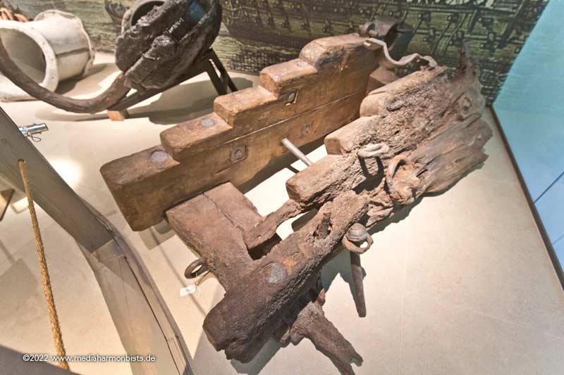
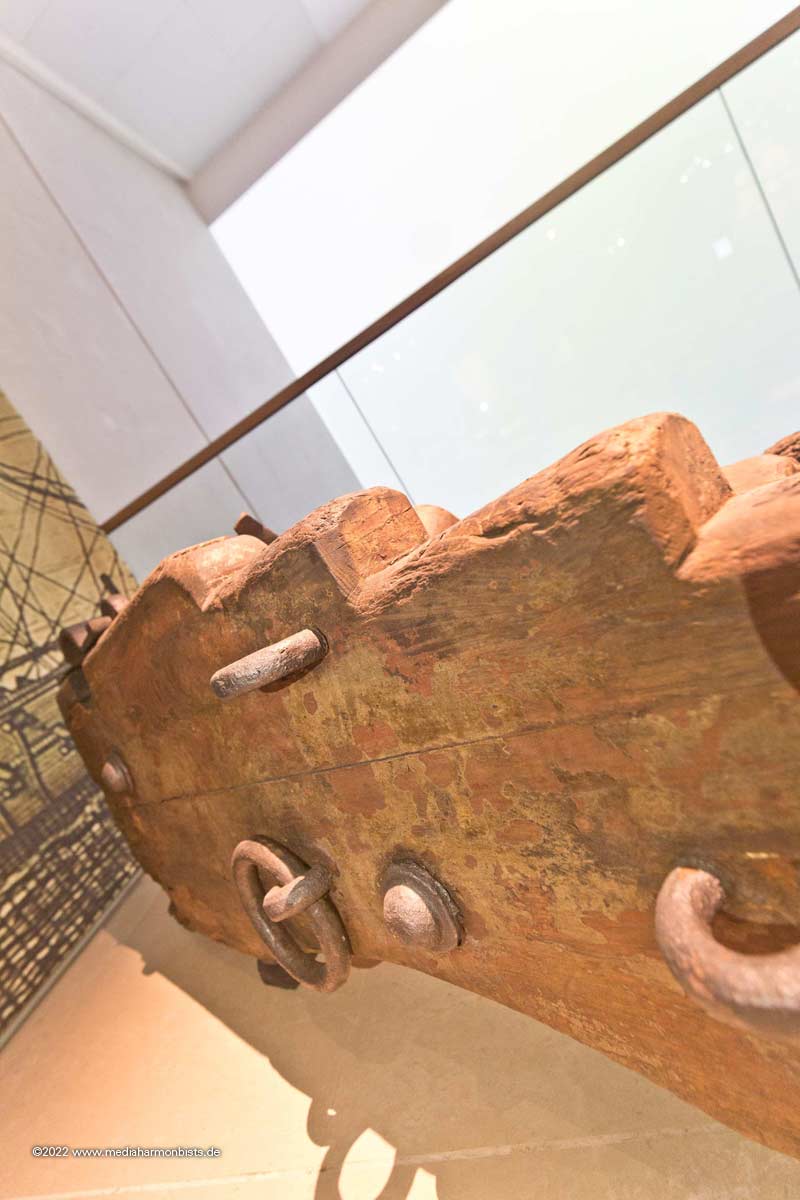
Fascinating to see the 1812 mounts. A total of 3 are on display in 2 rooms. I had to climb a little behind the display, but fortunately no one complained 🙂
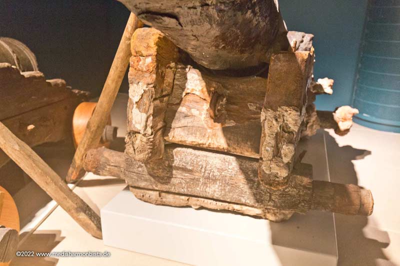
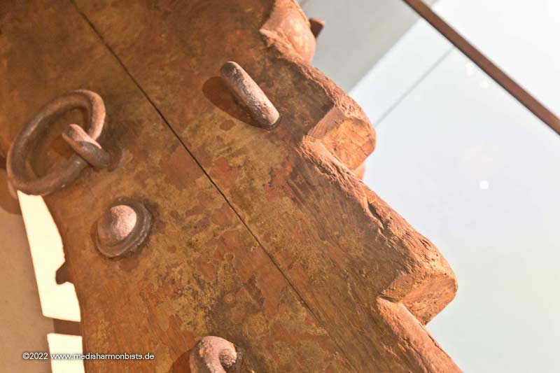
You can see the mounting holes of the cheeks in the front and on the side.
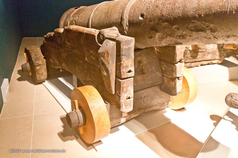
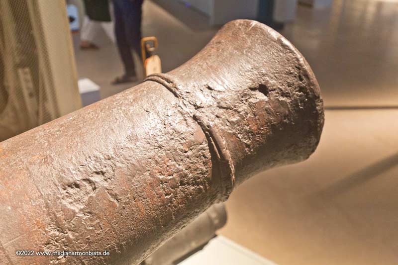
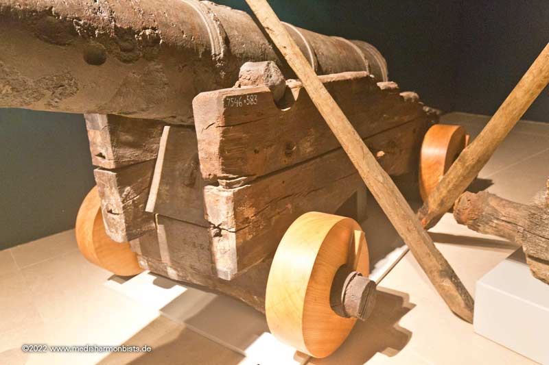
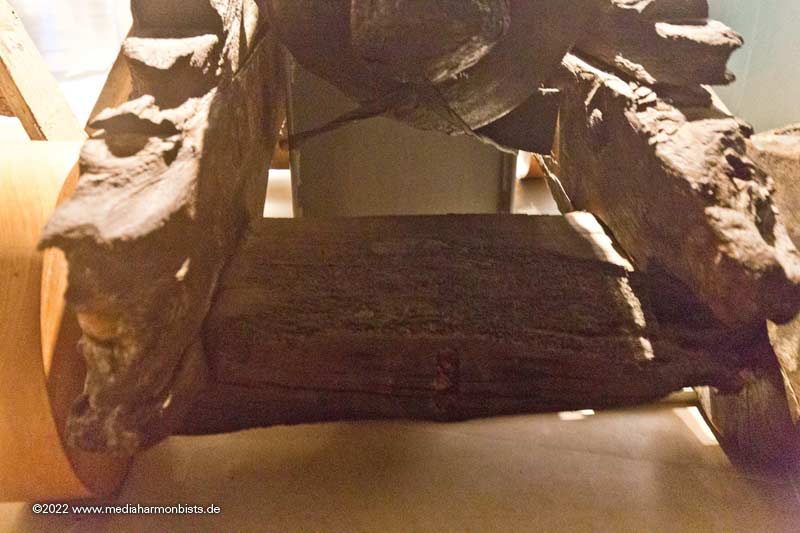
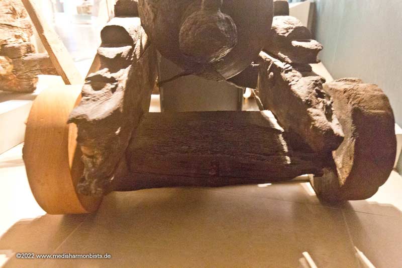
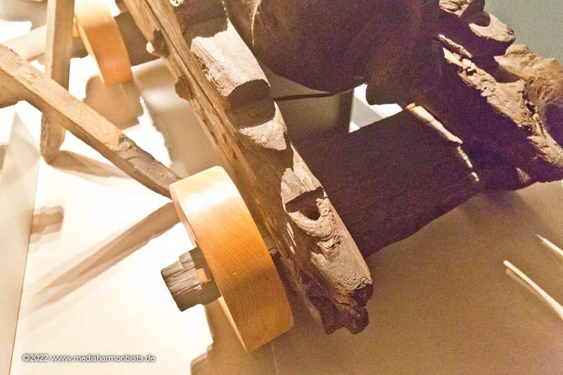
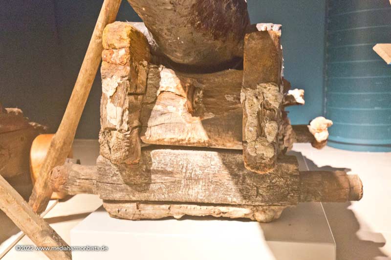
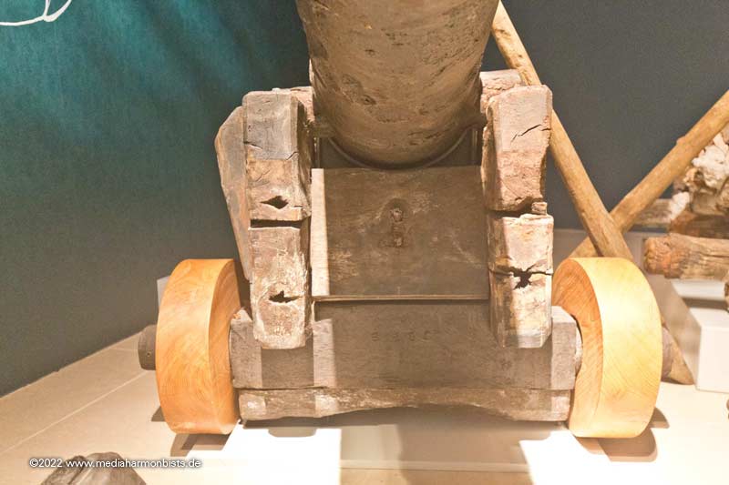
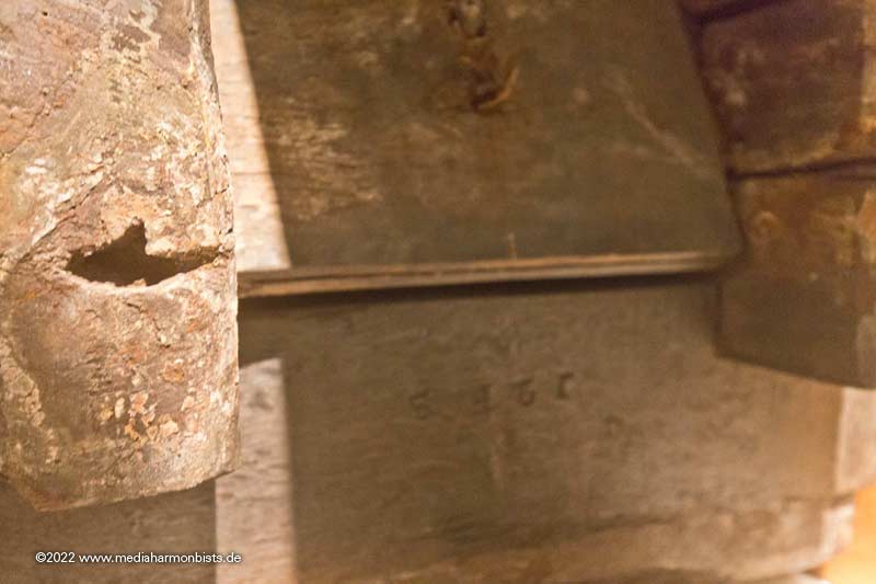
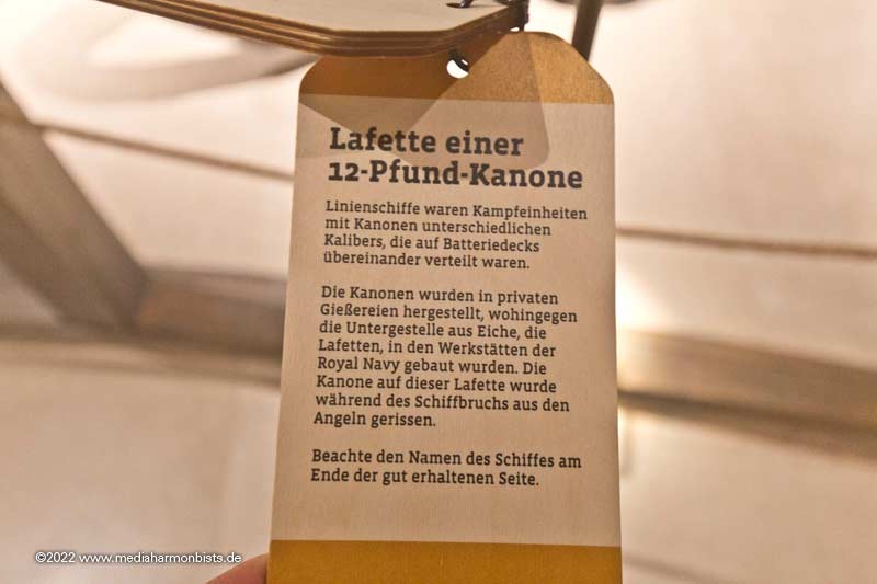
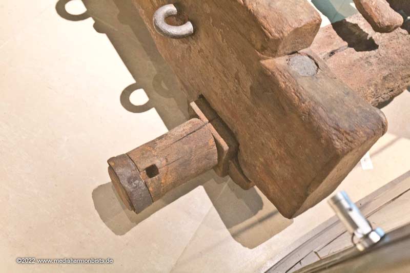
In the last picture you can see a label on the axle. I also never noticed the doubling up under the axle, possibly to serve as a slide if a wheel is damaged in action.
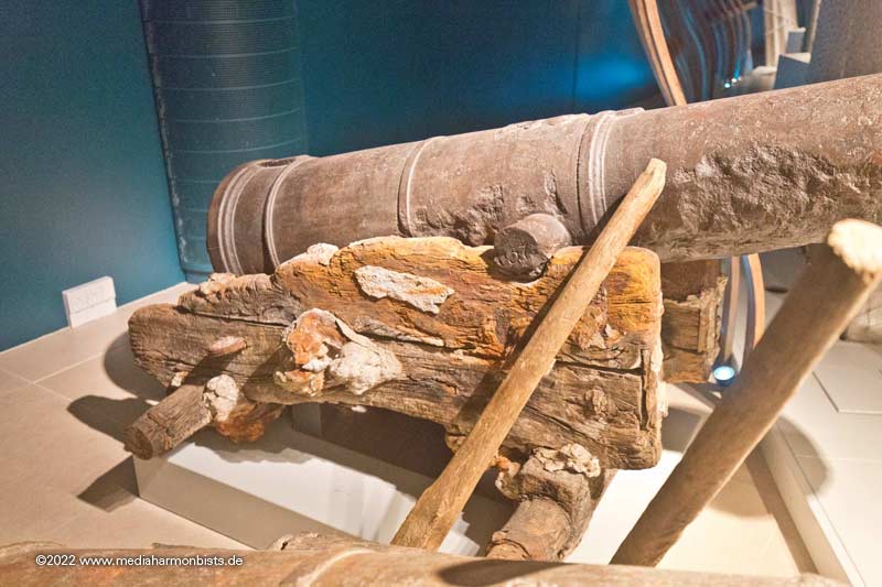
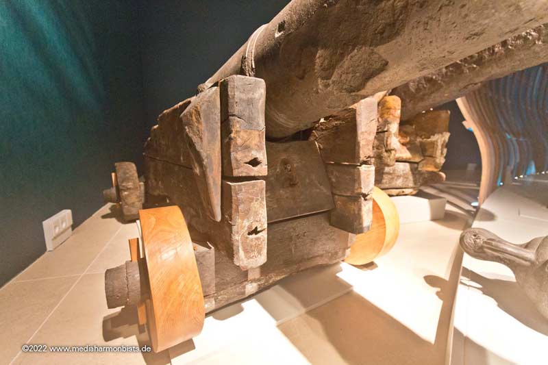
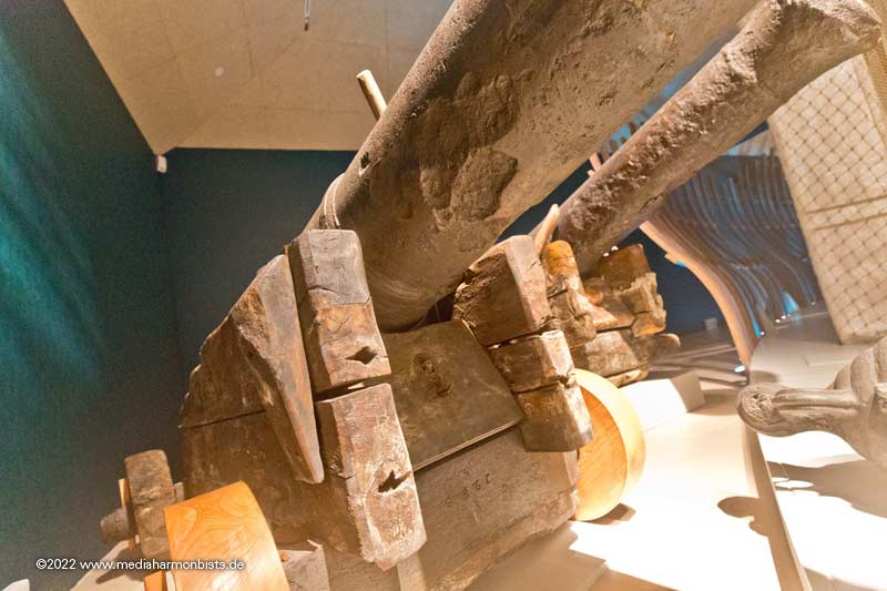
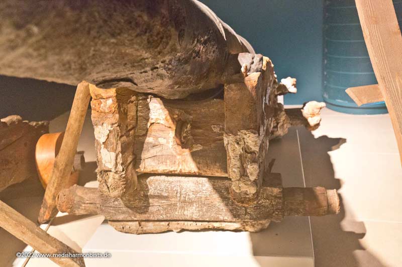
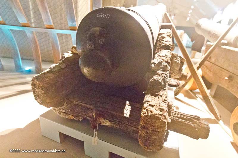
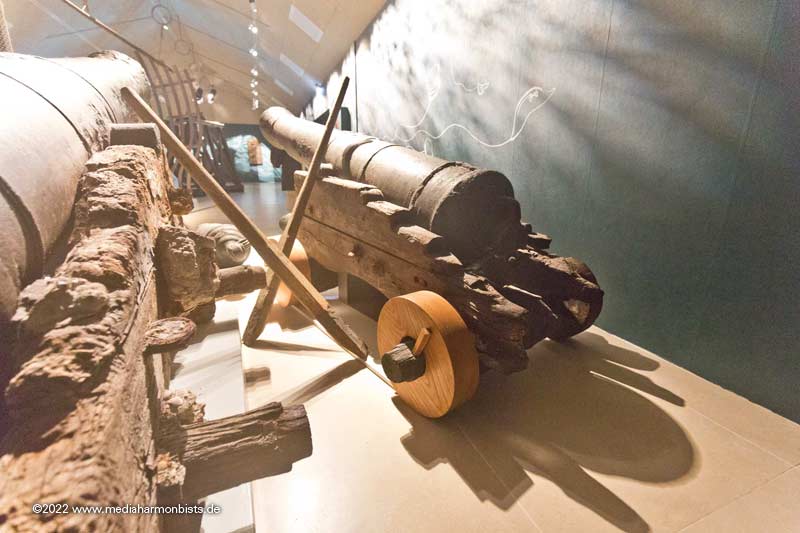
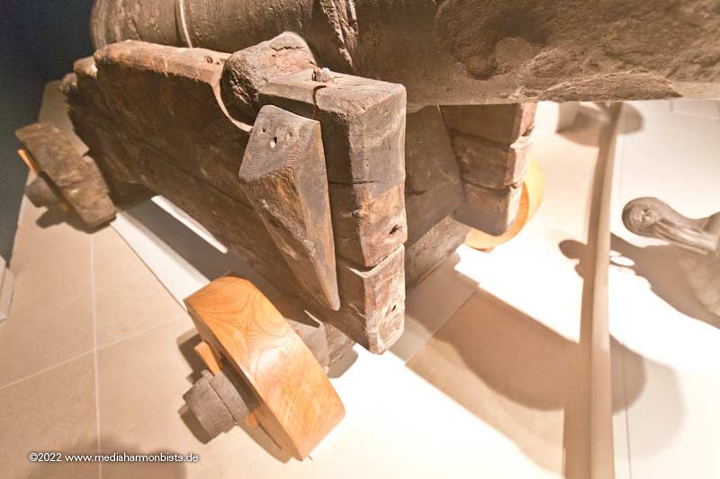
In another room is another carriage. What is fascinating here is that two layers of paint seem to have survived: Ochre over red.
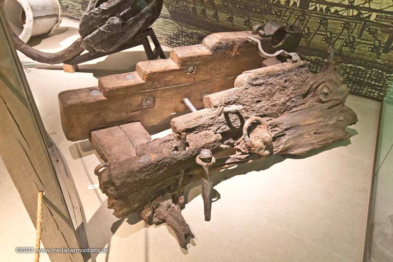
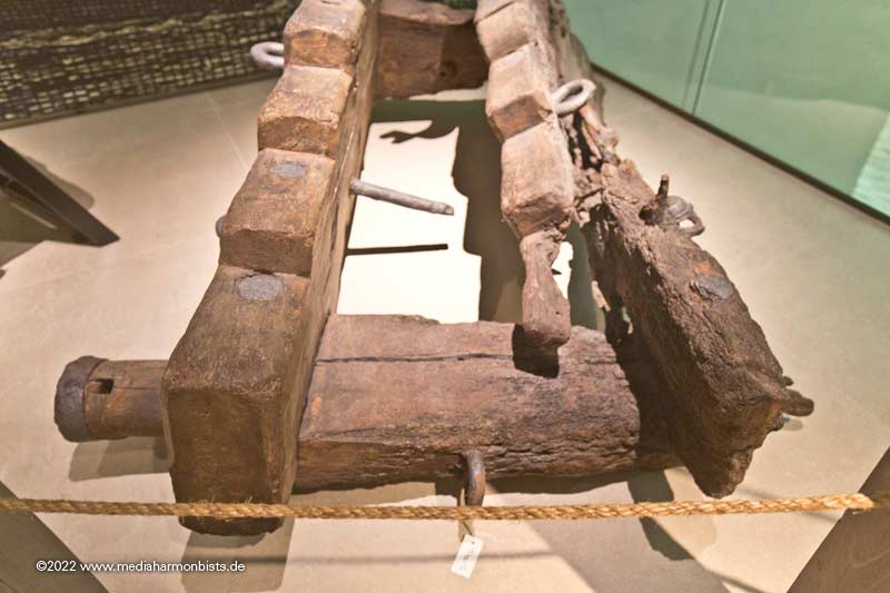
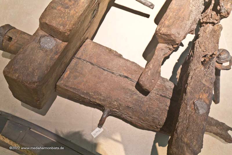
You can see the play of colours here. Red and ochre paint?
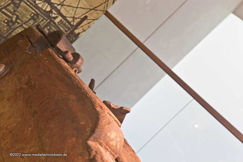
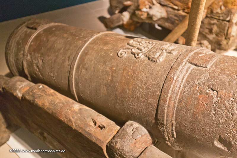
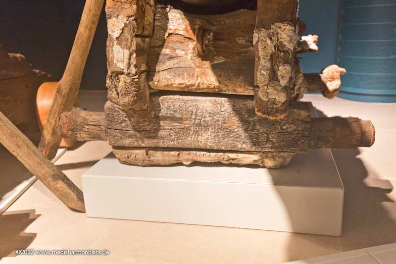
More difficult to see, the inscription of the rear end, to be read from the left: St. George
- tkay11, BLACK VIKING and mtaylor
-
3
-
-
And on it went in the text, or rather with the man glitter.
First attempt at the substructure of the upper deck. I still changed it afterwards.
Then the planks were caulked: Glued vertically on a duct tape and brushed with thicker paint, gives exactly the right width for the scale.
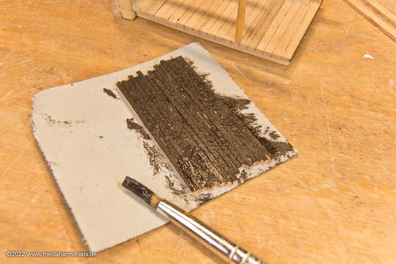
Freshly glued, it looks like newly tarred ...
... and after holystoning already a bit more "shipshape" http://www.shipmodels.info/mws_forum/images/smilies/icon_smile.gif
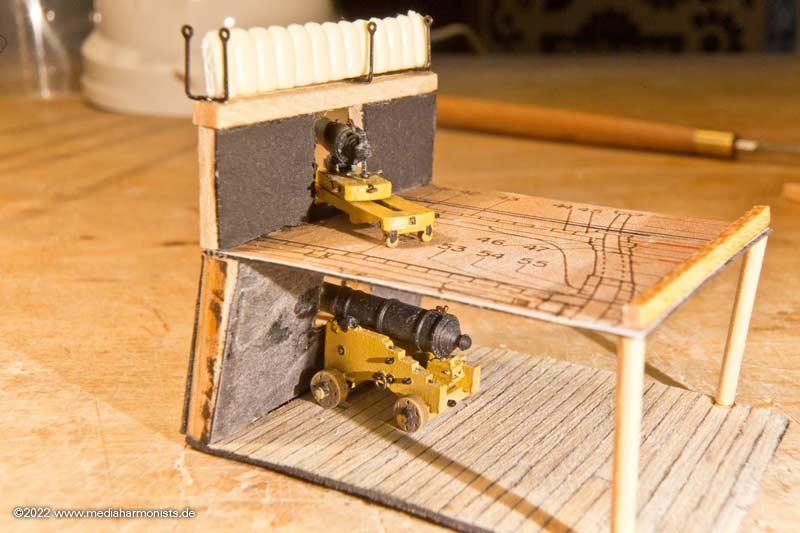
Adjusting the height of the Carronade ...
... and fitting test.
Fits, so close and put the gunwale on http://www.shipmodels.info/mws_forum/images/smilies/icon_smile.gif
Enjoy http://www.shipmodels.info/mws_forum/images/smilies/icon_smile.gif
And to show the size ...
... in this sense, all the best, DAniel- Prowler901, rybakov, mort stoll and 4 others
-
7
-
-
-
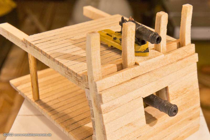
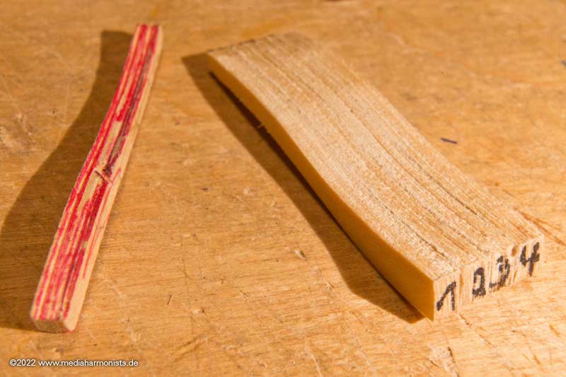
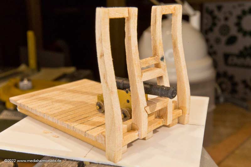
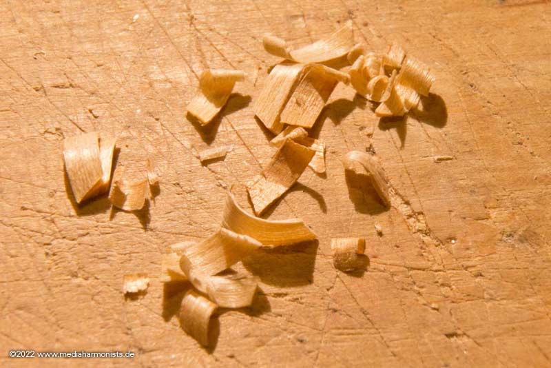
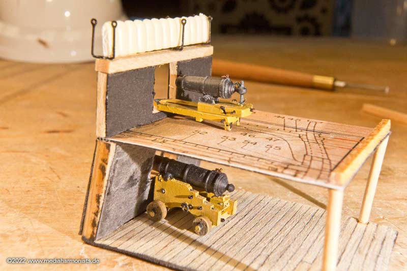
When the little wood hunger strikes ...
... then there it comes, the man´s glitter ...
... or dafi goes stray 😉
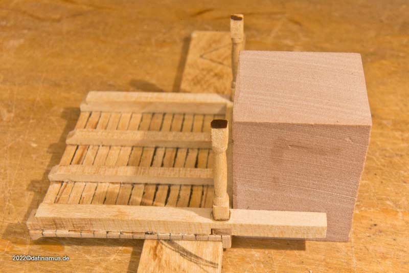
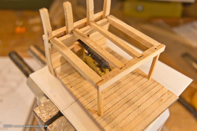
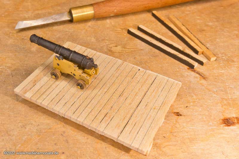
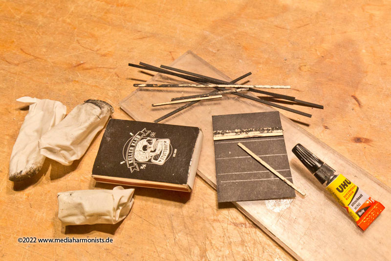
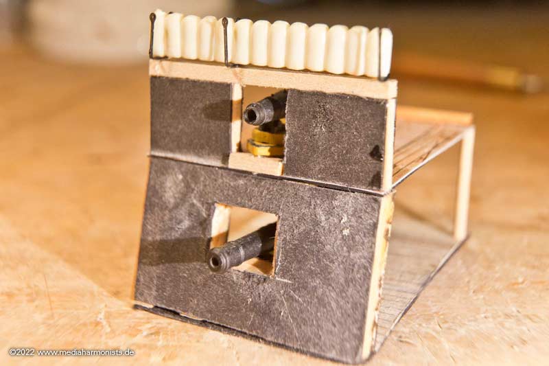
First of all I made a small deck, the size of a matchbox ...
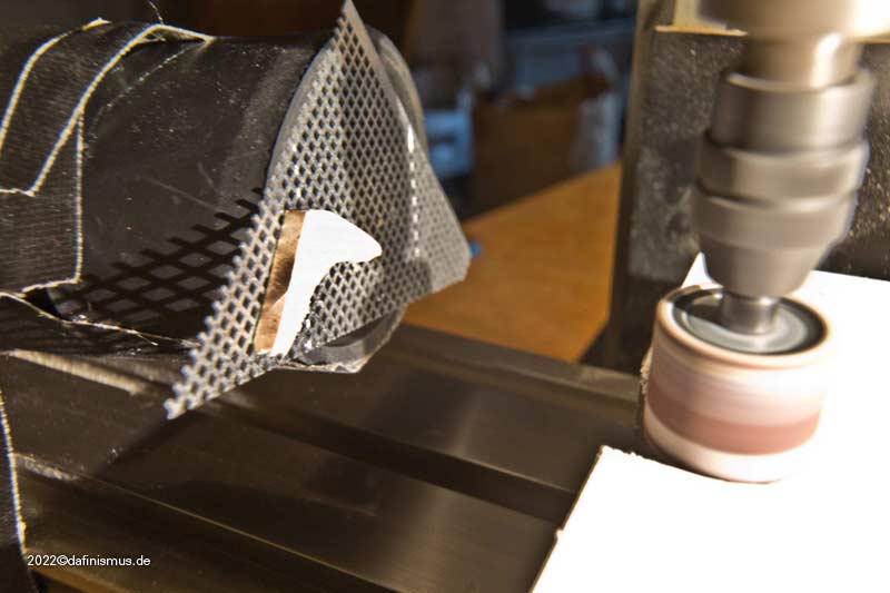
Then I put a round sander into the stand drill and worked out the frame shape.
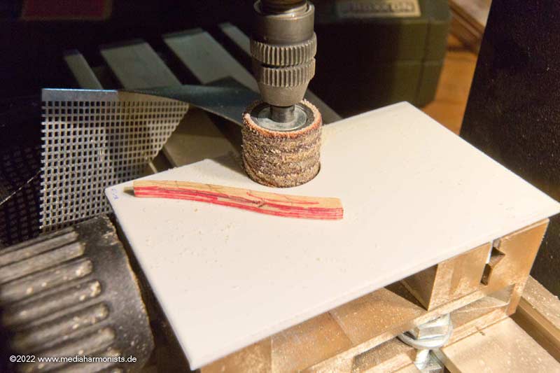
After I had to look for my workpiece 3 (!) times in the hoover bag, a perforated plate was placed in front of the hoover´s tube!
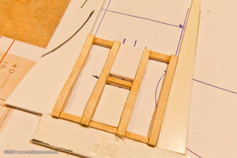
Then I glued 4 blanks with double sided tape on top of each other and sanded them as one piece into the frame´s shape.
A quick check - yup, it fits.
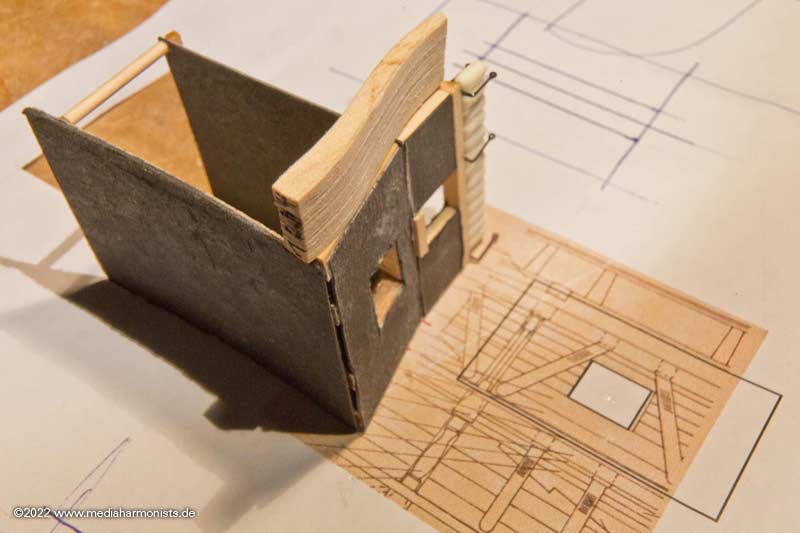
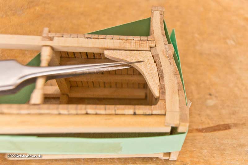
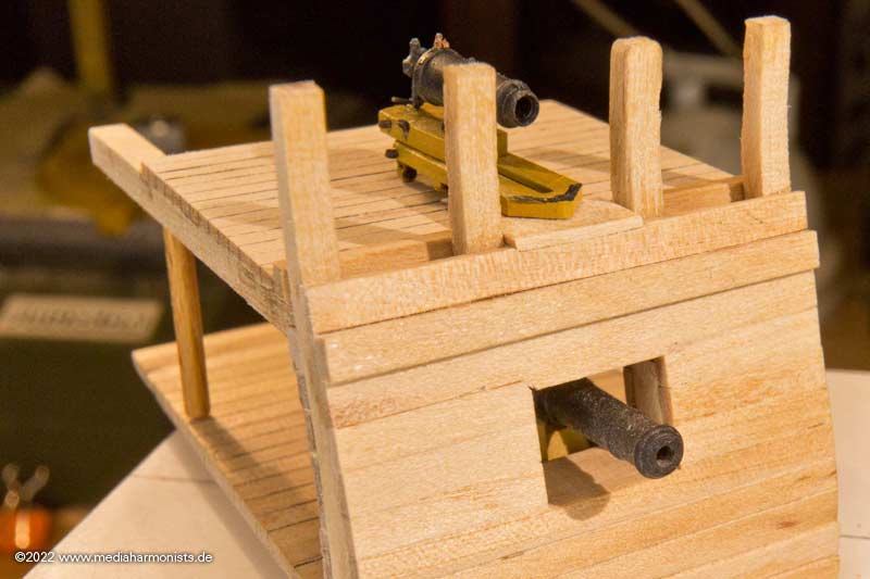
Made a jig out of polysterol strips so that everything can be glued at right angles ...
... and after curing the next fitting test.
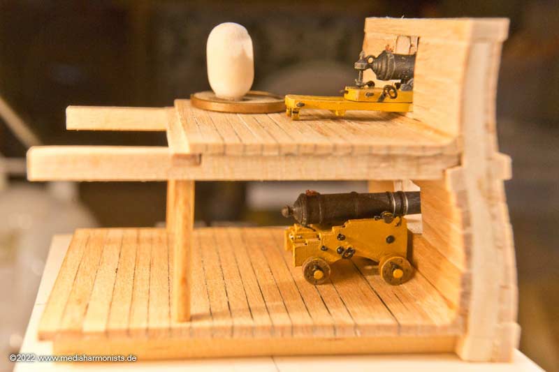
Meanwhile, the gun visits its new home.
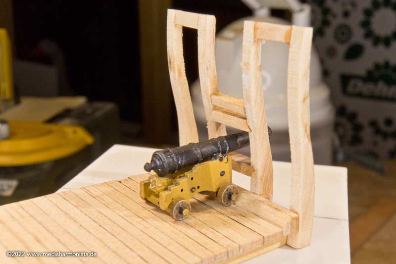
The barrel is in the center - yup it fits too
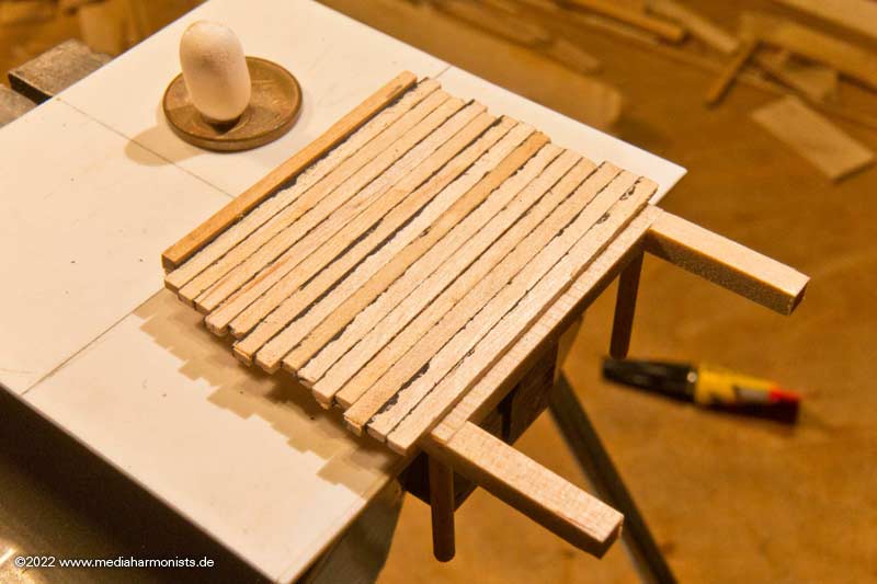
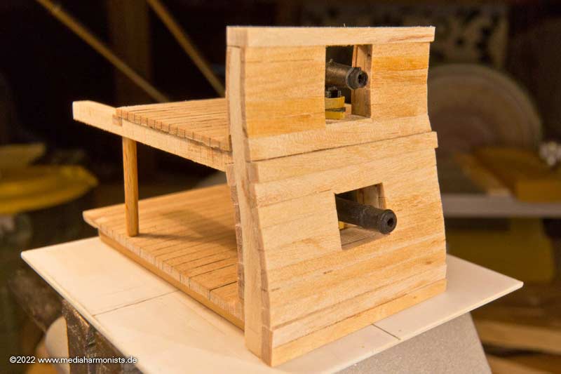
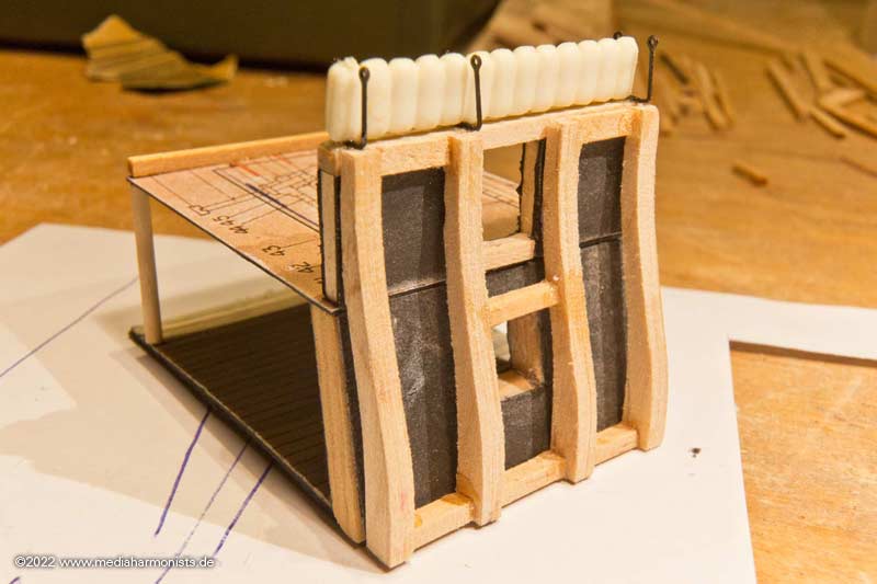
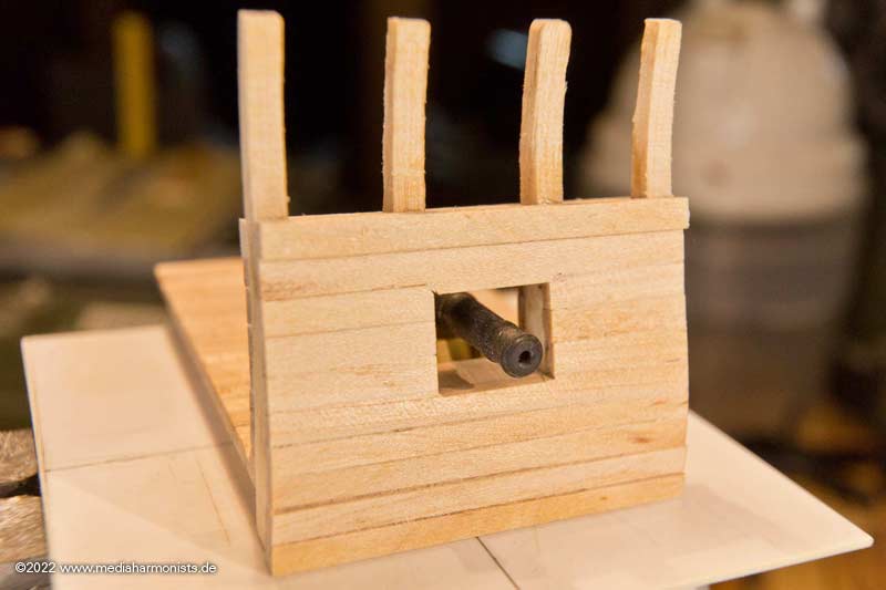
So I glued on the planks on the inside, from bottom to top according to Marquardt: Waterway, then Spirketting, Ceiling, Thick Stuff below Clamp and Clamp.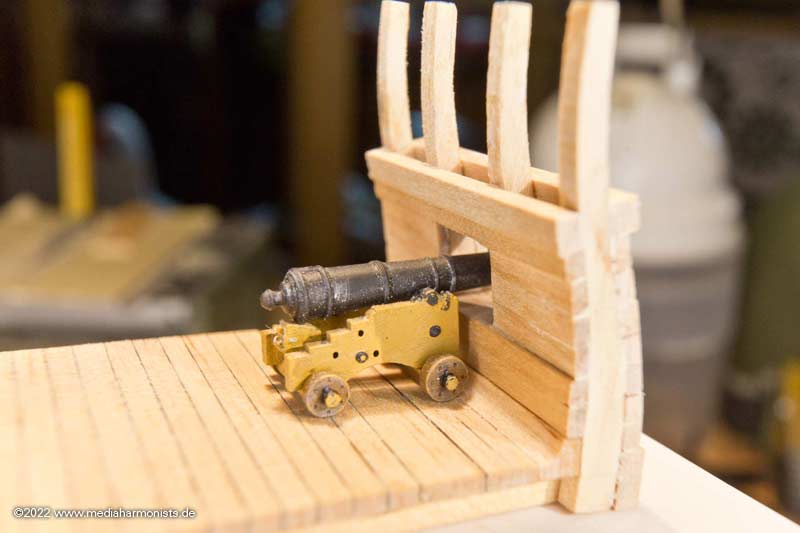
And then also closed the planking on the outside
And yes, here they come, the inevitable: the 1 cent piece and the TicTac 😉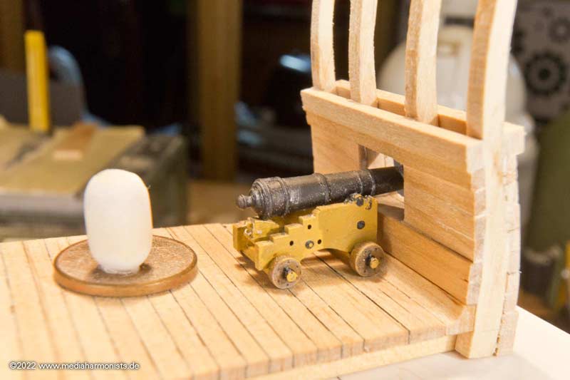
Best regards, Daniel- ScottRC, clearway, mort stoll and 5 others
-
8
-
-
Man´s glitter!
Well, after more than half a year I finally came back to my man cave and was able to do something. Man did I miss that!
In the meantime I was able to hatch some great ideas, so I dug out a matchbox ...
... and used it as the basis for a small pre-model.
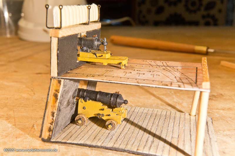
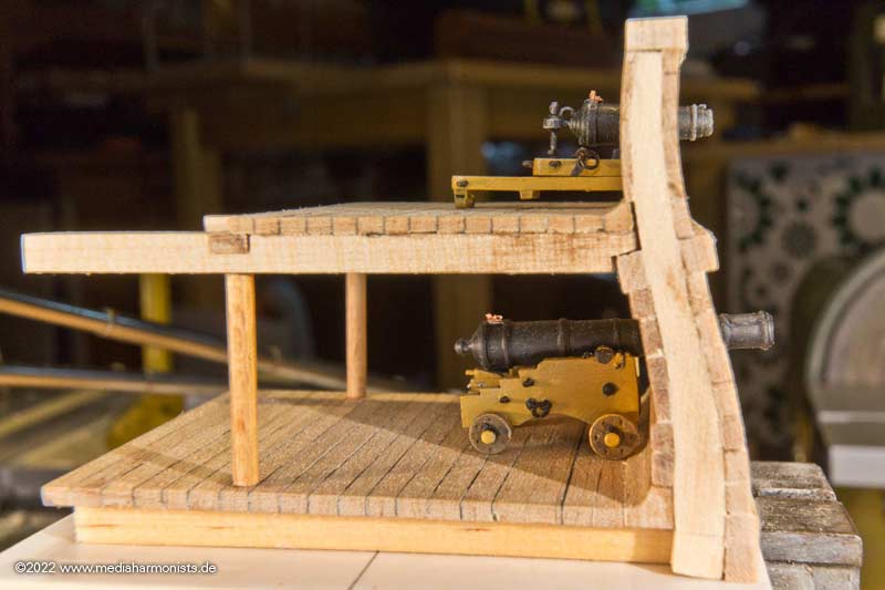
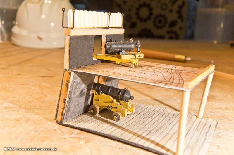
As usual, it's about being able to try out a few small things. Esepcially again and again about the use positions of the carronades.
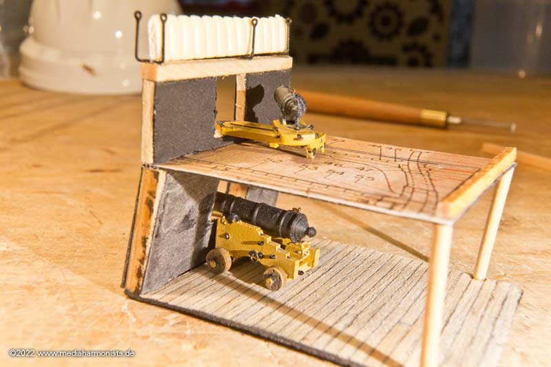
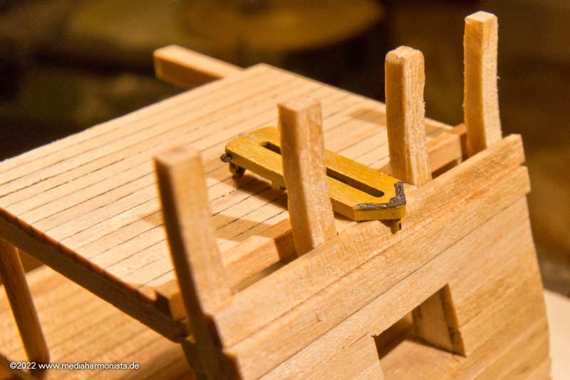
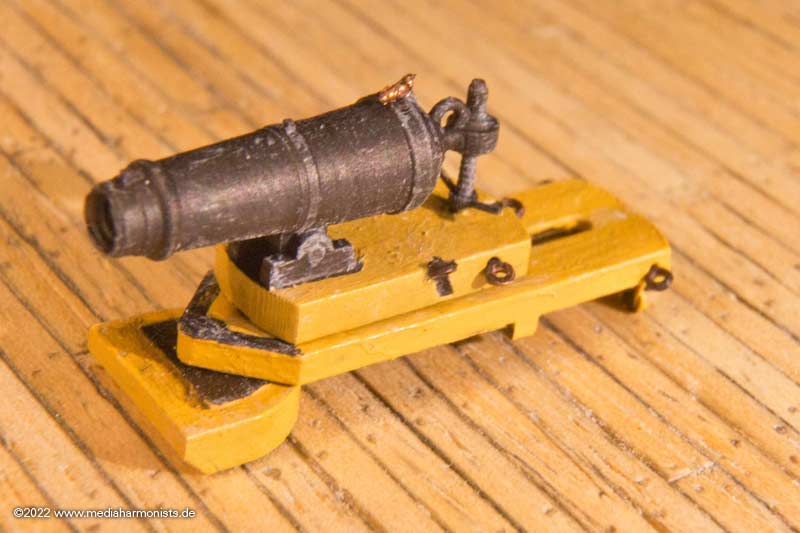
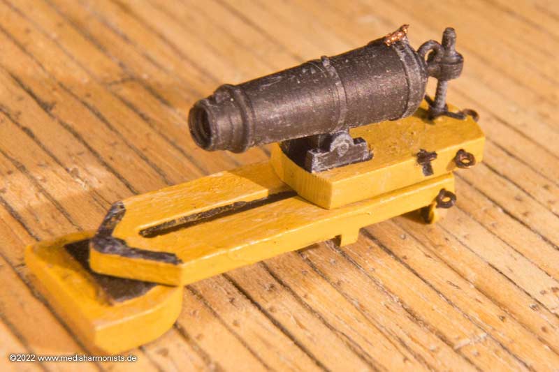
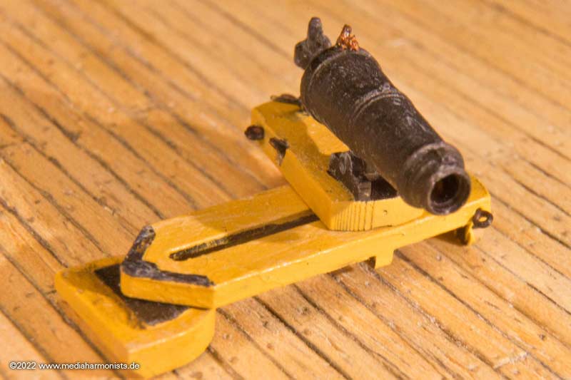
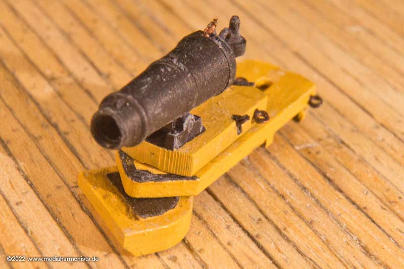
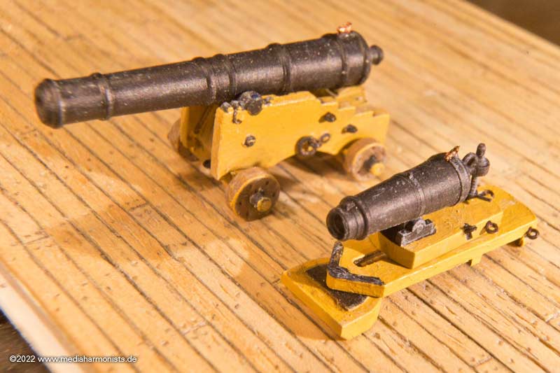
The guns are also slowly coming into the home stretch. It's always good to be able to keep an eye as a model builder on the programmer. The printing supports have been optimised so that the parts can be removed with as little reworking as possible, and the model construction itself also leads to details being improved in order to make them easier to paint. Here is the 24-pounder.
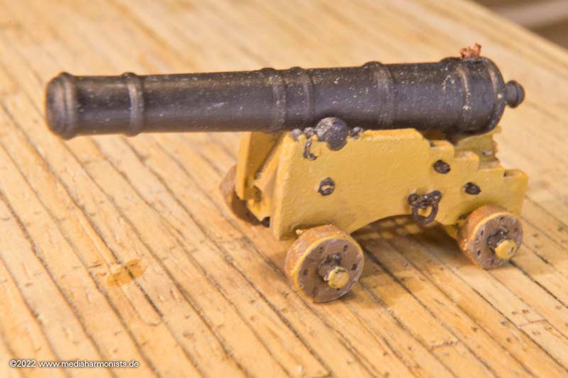
Beautiful details like the coin´s handle and the retaining cord of the stool bed are just great to look at, as are the fittings on the underside - just too bad they are mostly hidden.
Meanwhile, for the carronade, I decided to leave the barrel in one piece with the upper carriage. Because of the height adjustment screw, changing the elevation was difficult to adjust anyway or would have been too fragile. The swivel radius of the skeat around the pivot pin, the sliding way and rotation of the upper carriage were kept.
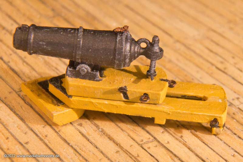
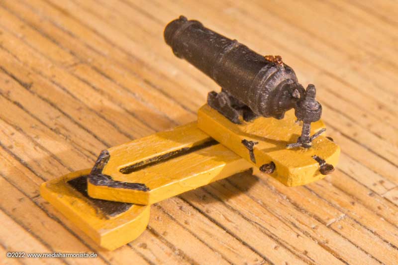
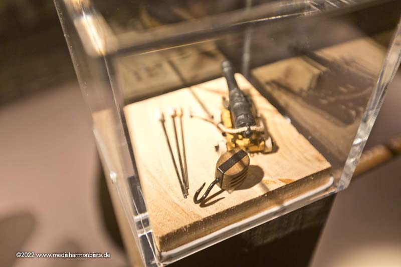
And here's a little family picture.
And then came the man´s glitter.
XXXDAn- Ian_Grant, mort stoll, rybakov and 3 others
-
6
-
-
Wonderful build and great discussions, I love it, congratulations!
The main sheet tackle spreader was not introduced until quite a while after Trafalgar. That is why I omitted it in the etch set.
I am not sure but I think it was also taken of the ship a while ago. Just have the eyebbolt on the hull, a length of tackle and that is it 🙂
All the best, DAniel


USS Constitution by dafi - Revell - PLASTIC - To Constitution and beyond ...
in - Kit build logs for subjects built from 1751 - 1800
Posted
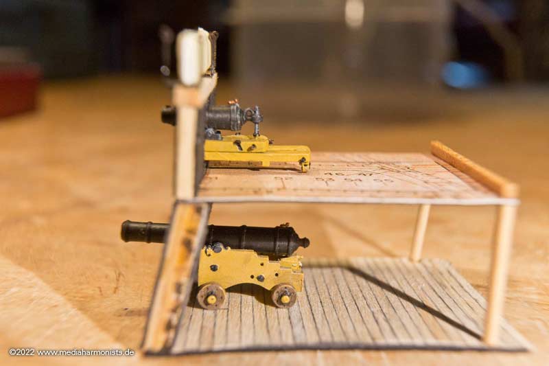
And seen from deck´s height it would look like this ...
... scnr 😉
XXXDAn