


dafi
-
Posts
2,284 -
Joined
-
Last visited
Content Type
Profiles
Forums
Gallery
Events
Posts posted by dafi
-
-
Thank you Alan, my pleasure!
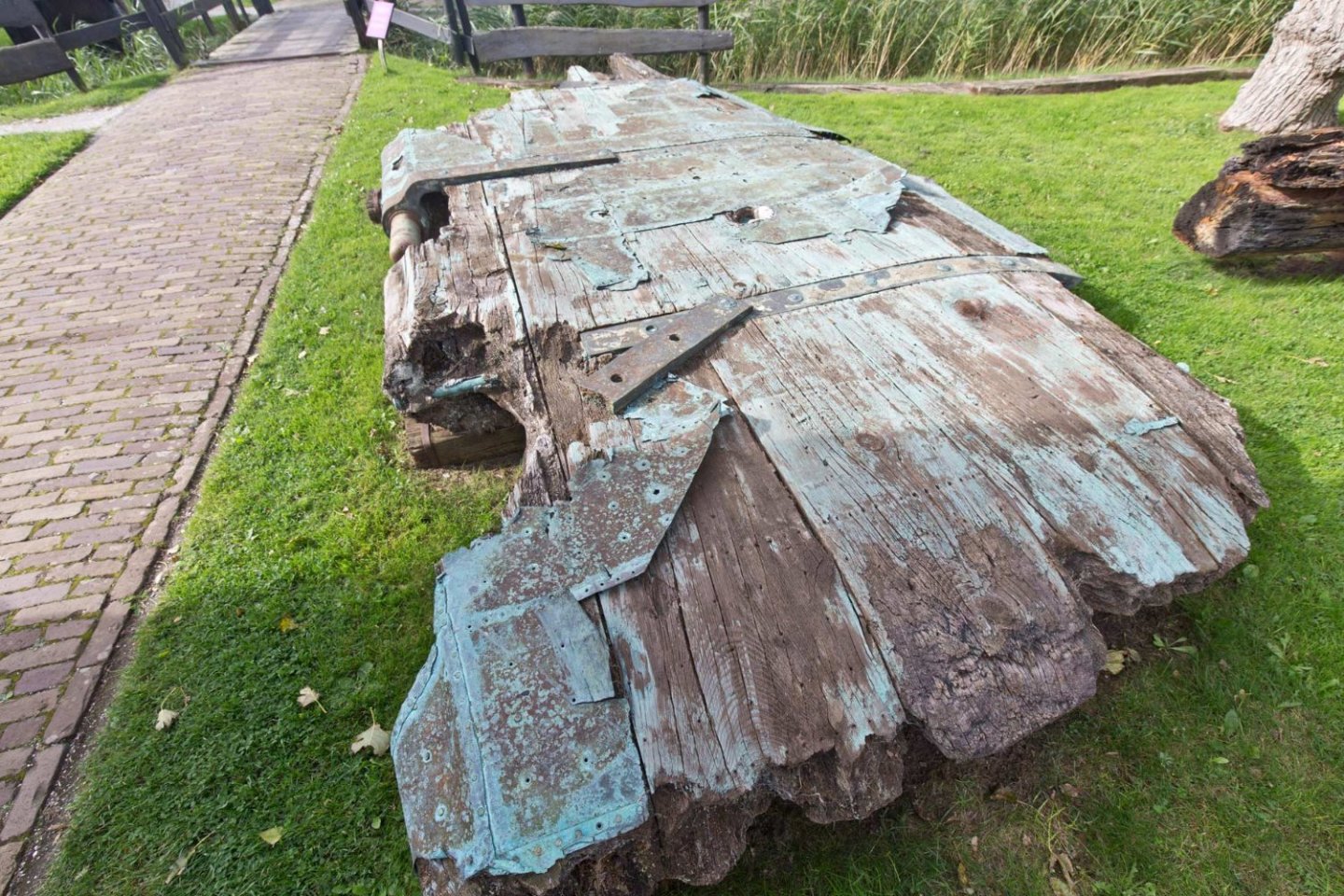
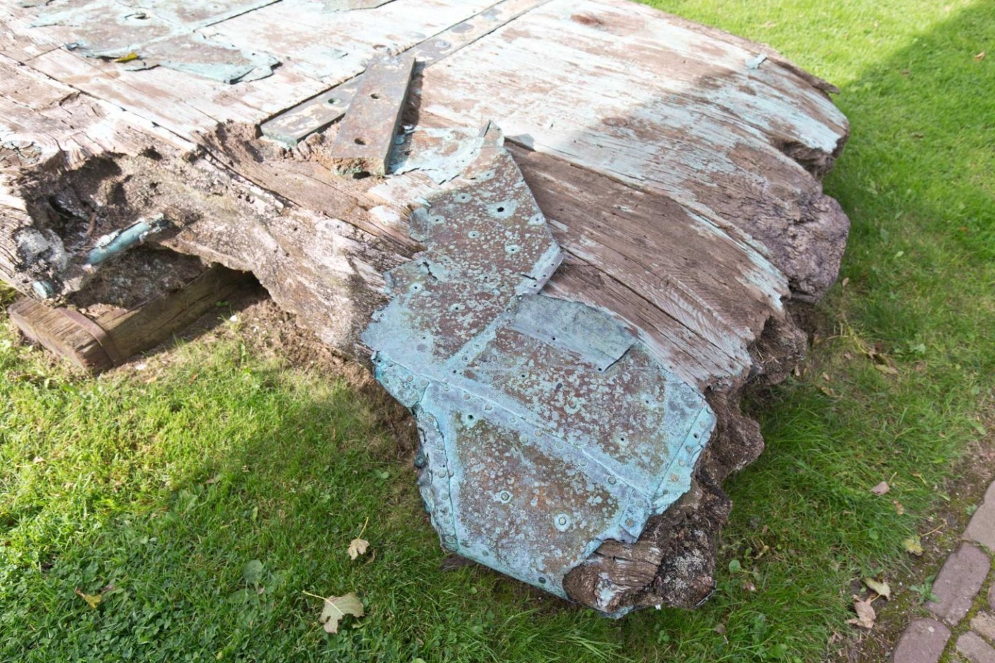
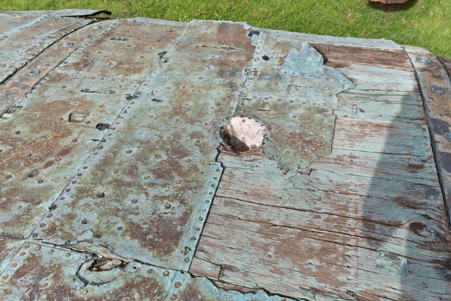
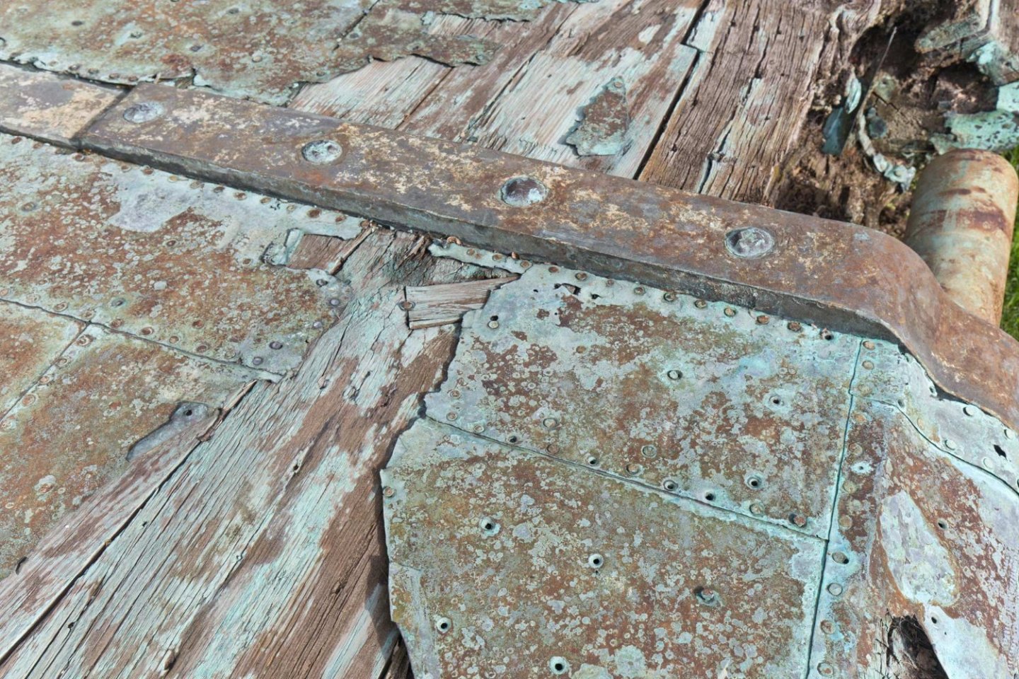
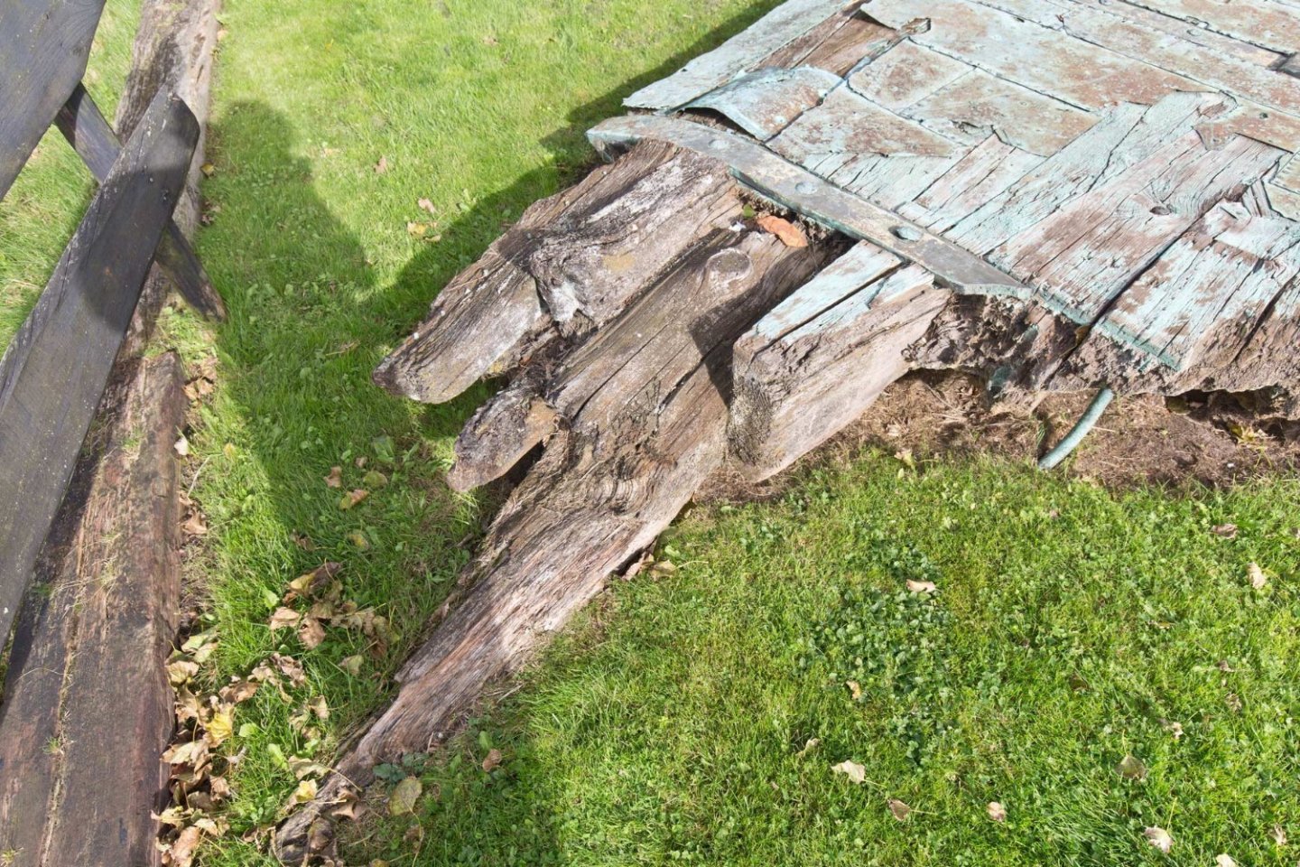
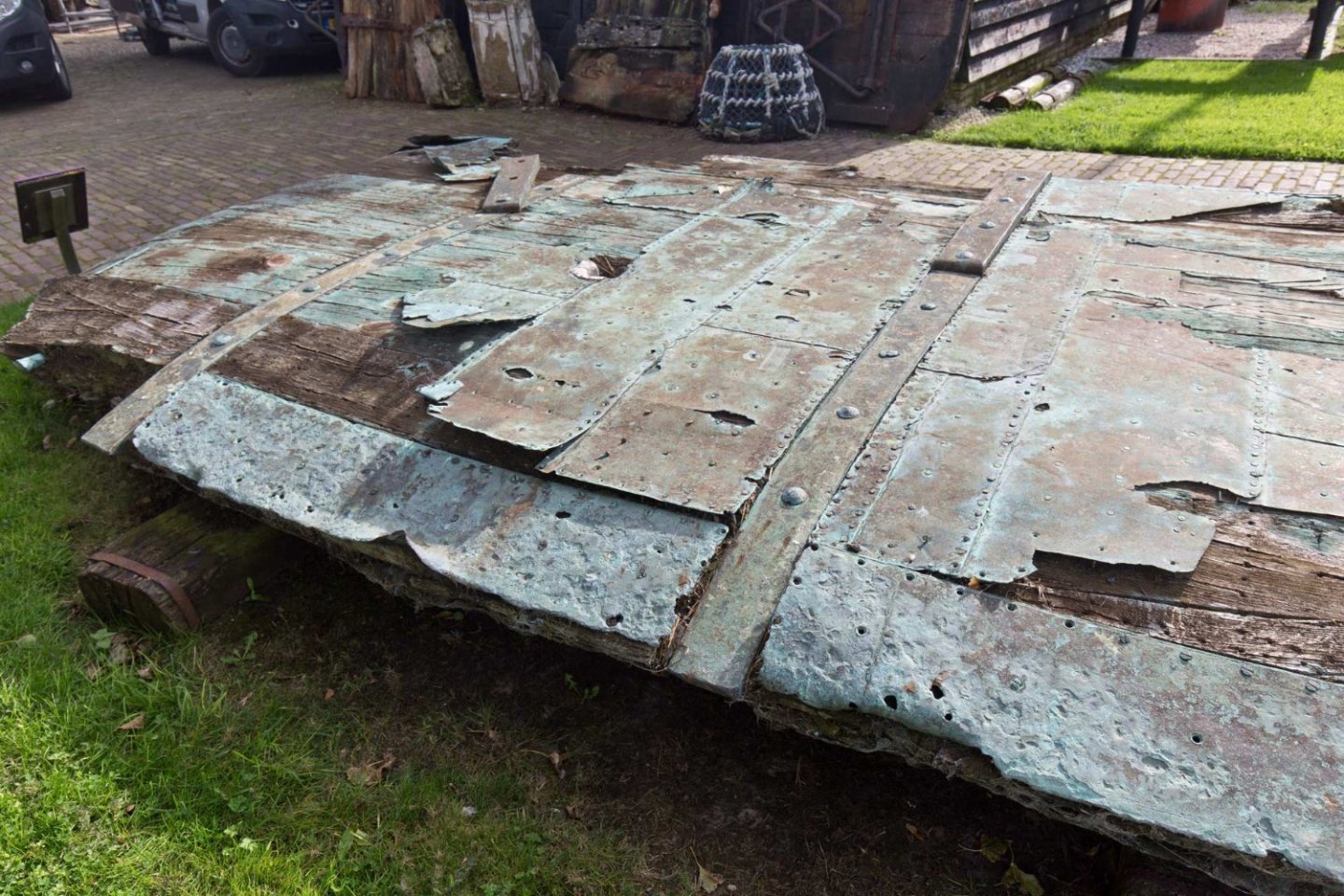
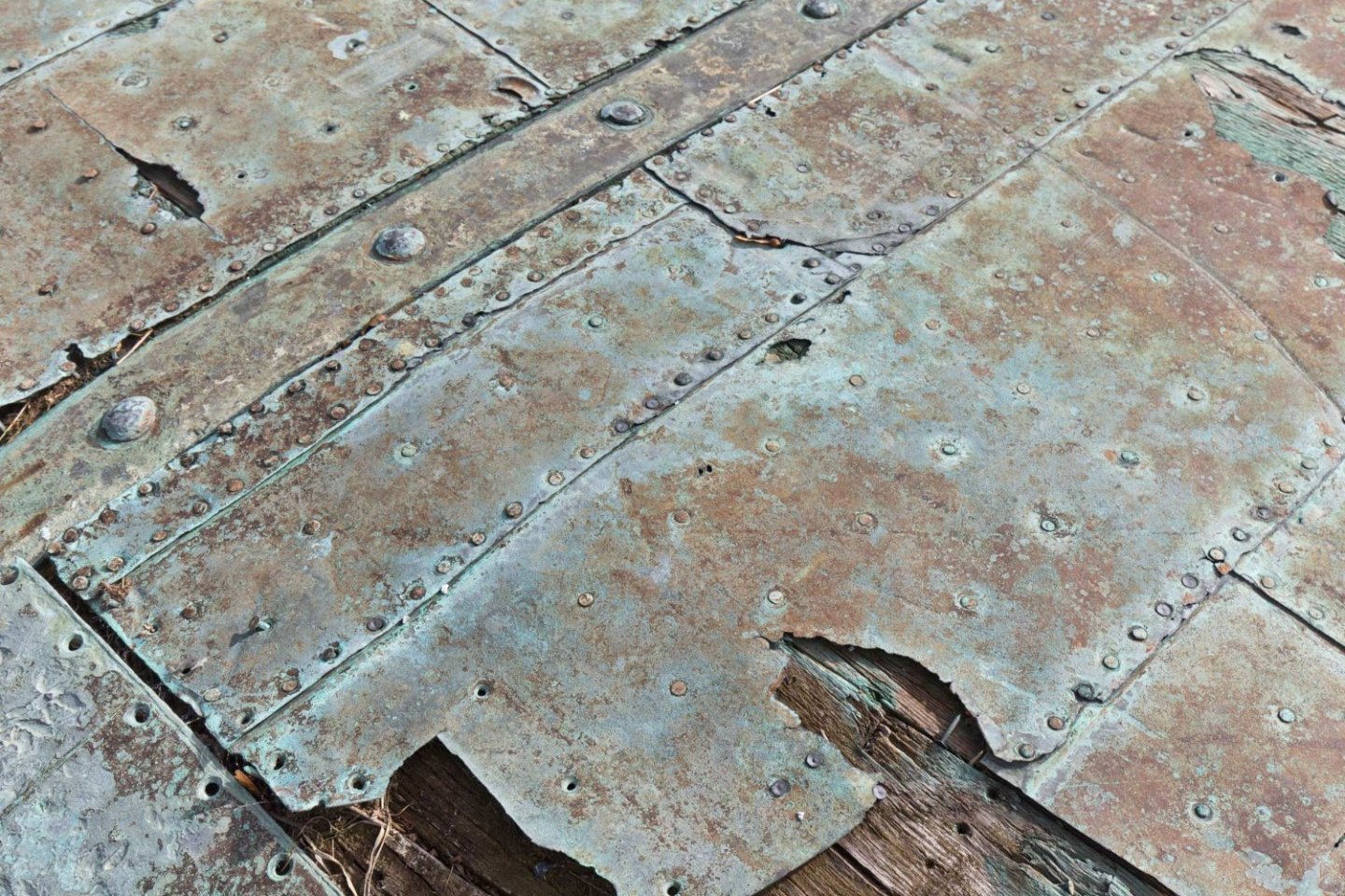
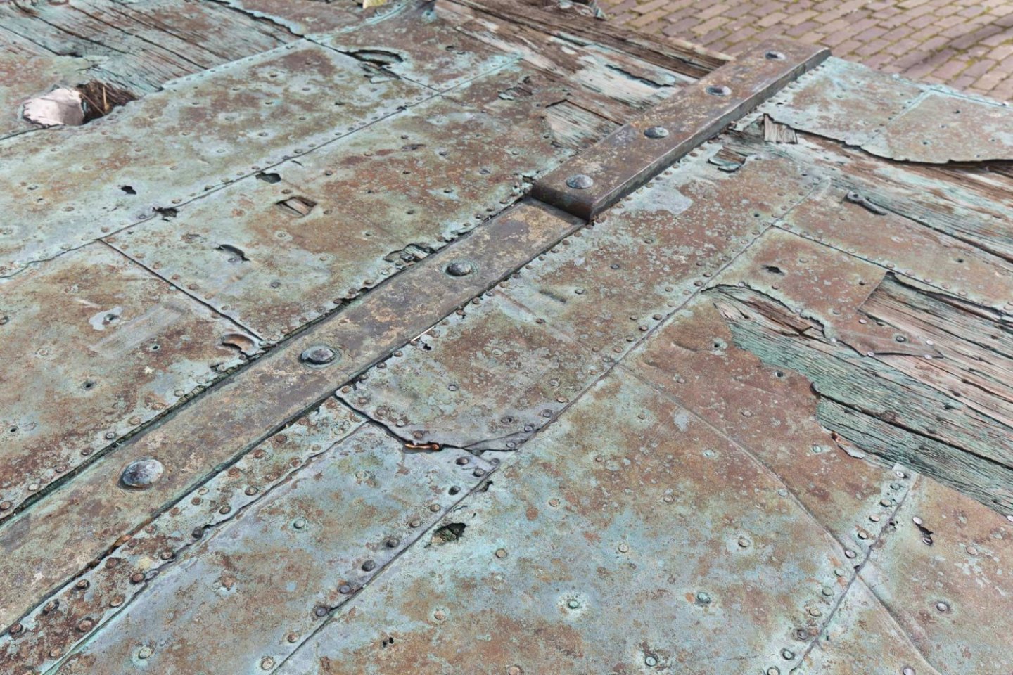
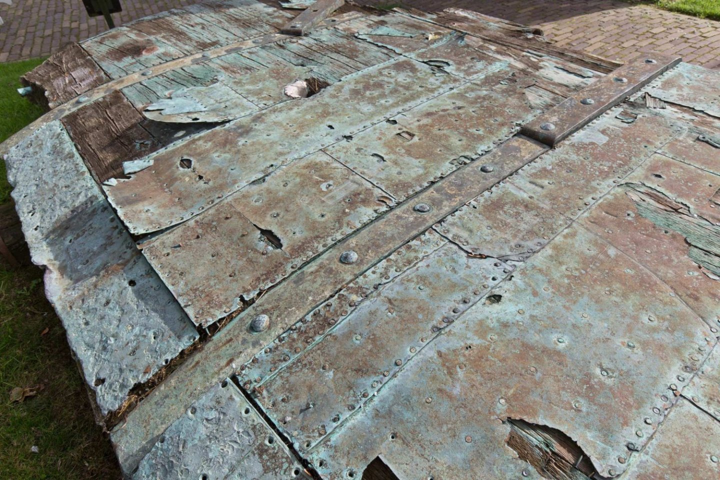
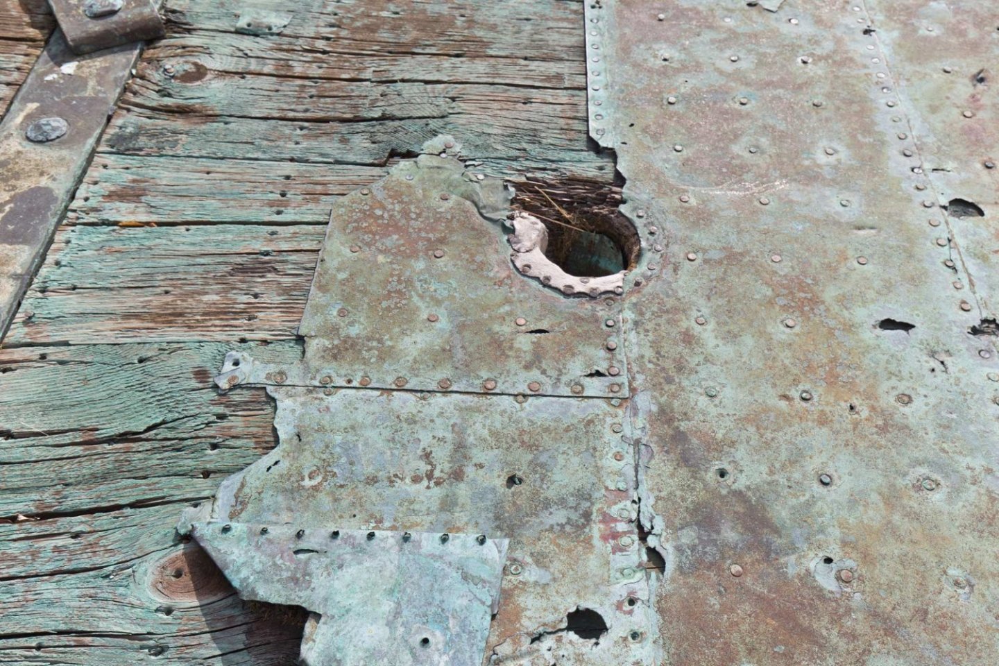
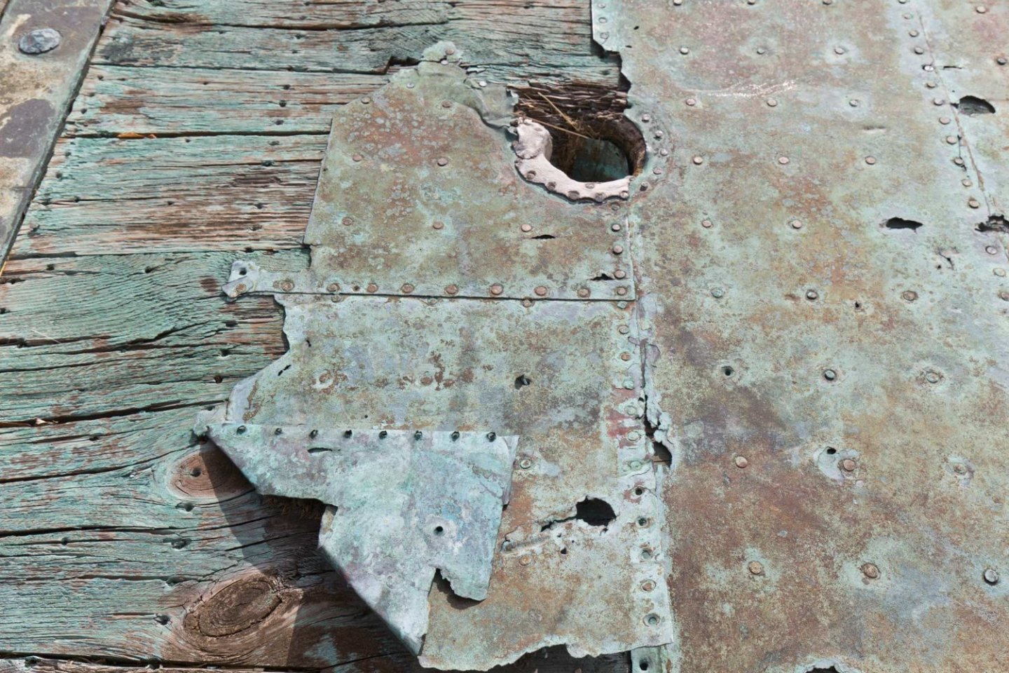
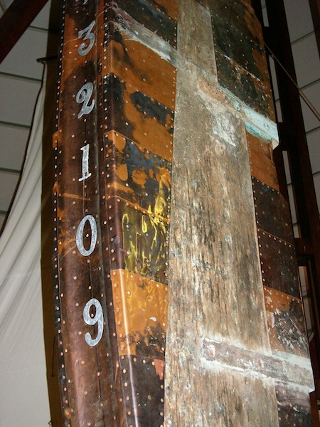
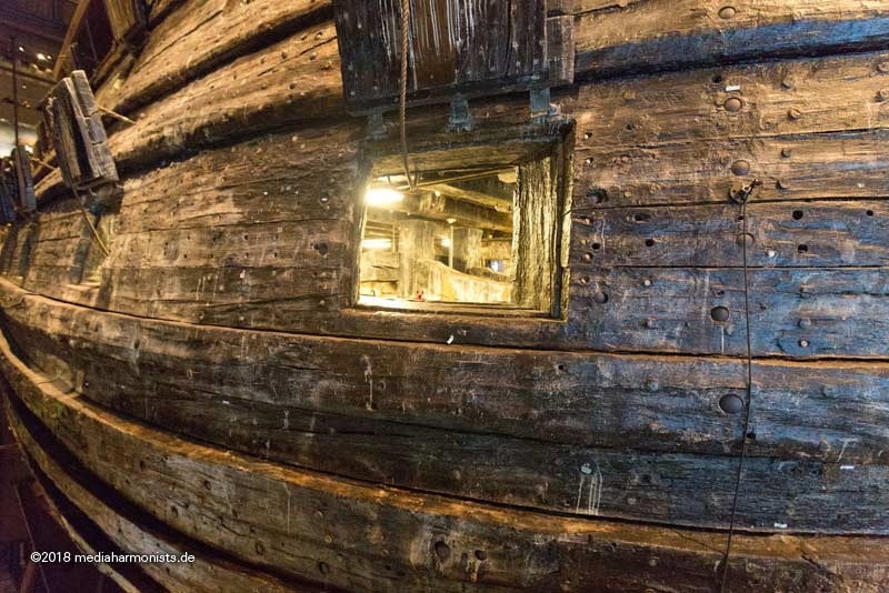
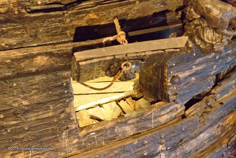
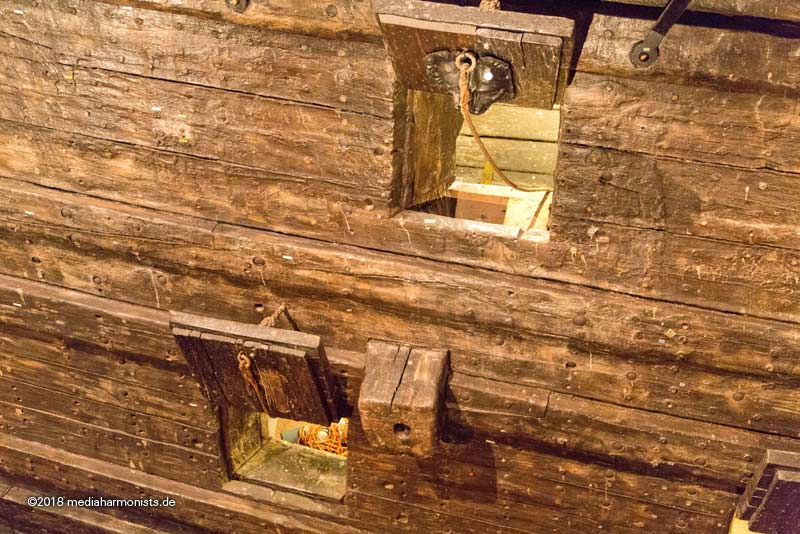
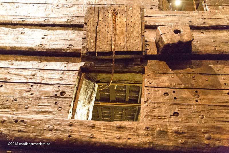
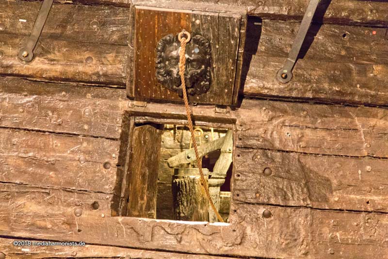
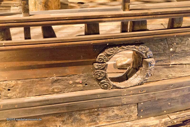
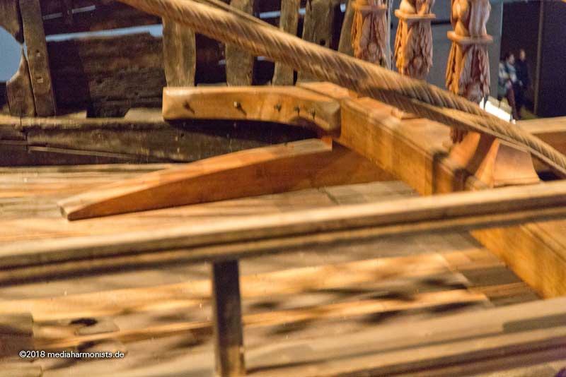
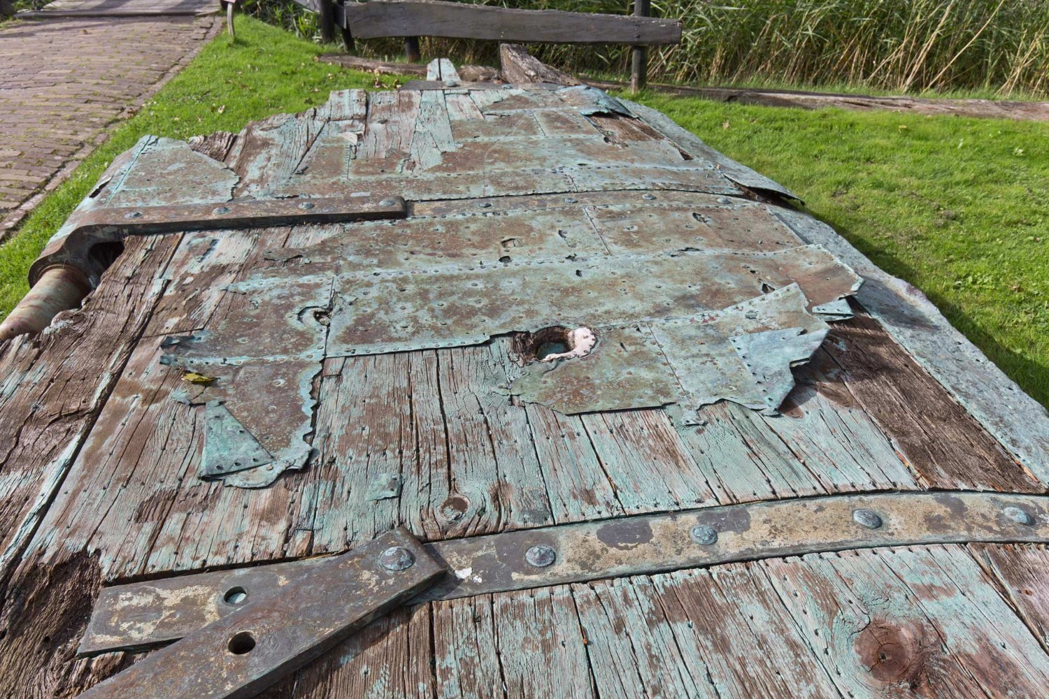
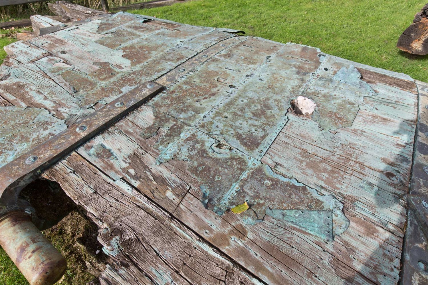
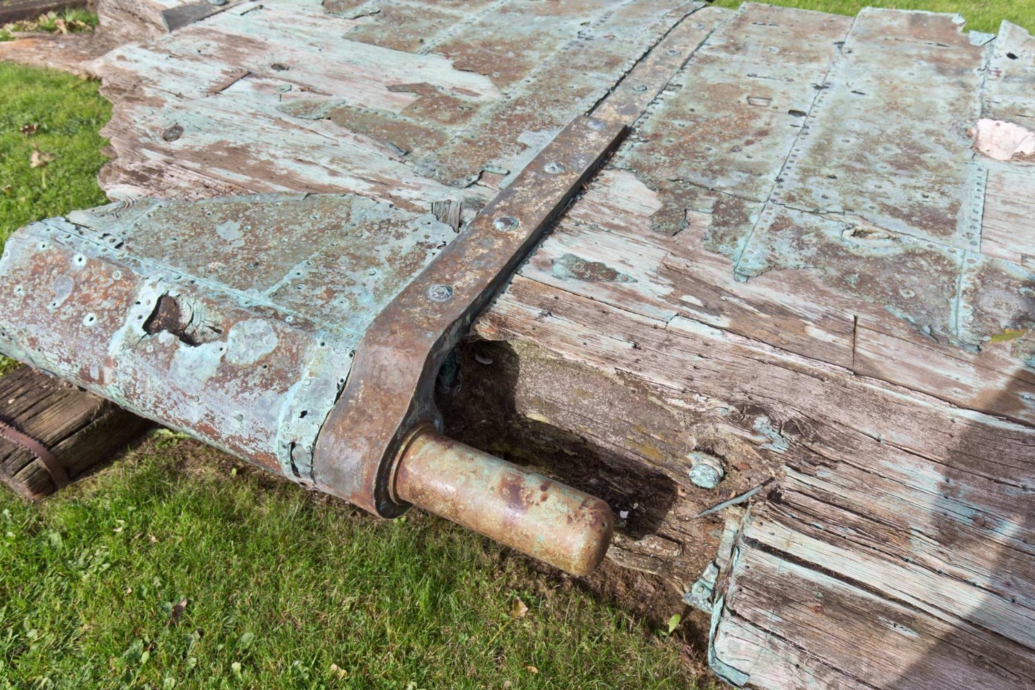
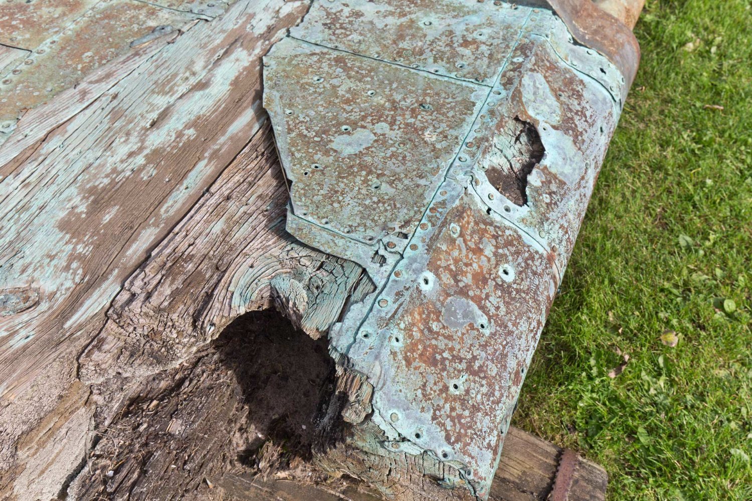
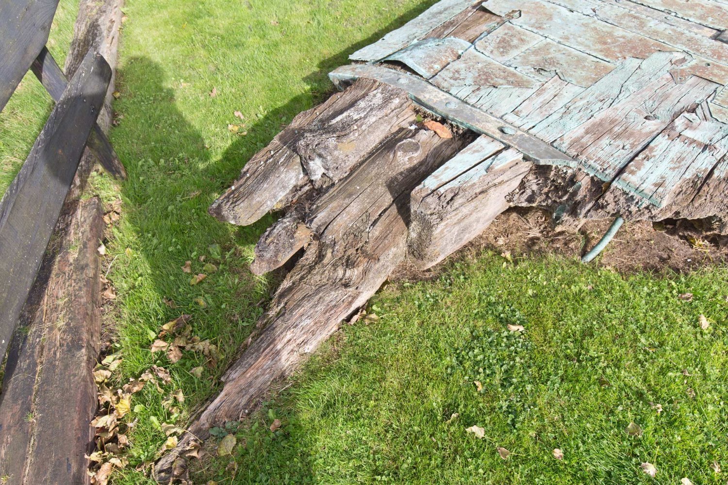
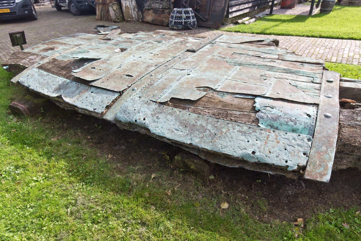
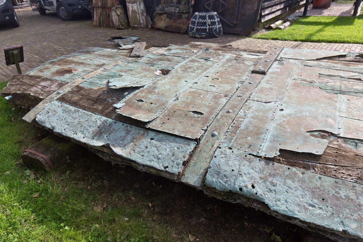
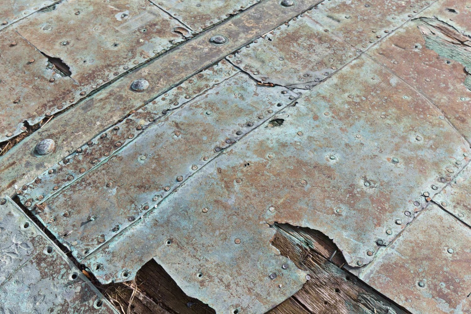
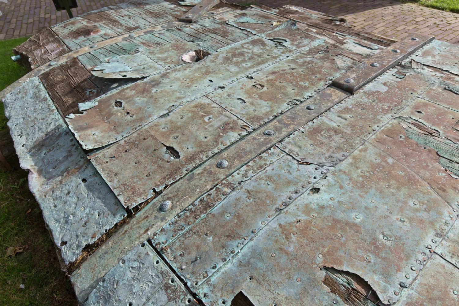
Her some more real old copper, seen in museum in Oudeschild Texel, where the famous dioprama of the roadstead with the dutch fleet is shown.
Just enjoy the laying pattern, the adjustments in the edges and around the fittings, the patches and my favorite piece: the hole of the rudder jeer 🙂


-
-
And if you put a white drap under the whole area and strech it even towards you covering your lap, then also much less parts will not pay a visite in one of our paralell universes 🙂
-
Good start nevertheless 🙂
I would use white glue for wood from the DIY-department. Also use it as well as the black paint before binding in the heart.
Good success, Daniel
-
Nationaal archief Den Haag, Number 1.01.47.21 - Inv. Nr.: 112.
I also added it to the entry
XXXDAn
- mtaylor, Sizzolo and Thukydides
-
 3
3
-
Here some additional remarks from my collection of historical copper:
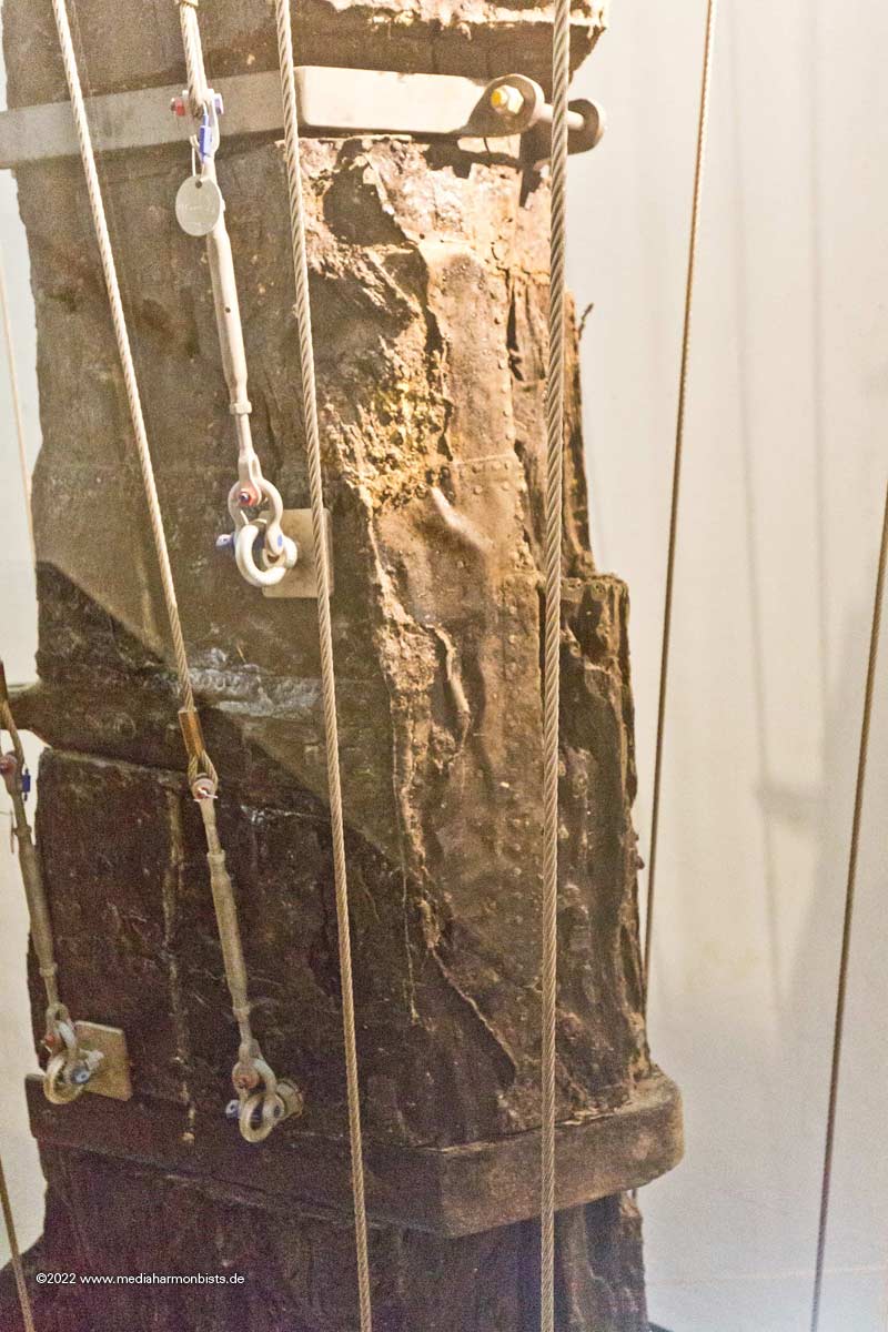
St. Georges rudder in Thorsminde, much patched but apparently mostely the lower plate overlaping the upper one.
A spanish vessel lower one overlapping the upper one (drawn from a perished french forum)


A picture of Bruno Orsel, unknown merchant vessel showing the same
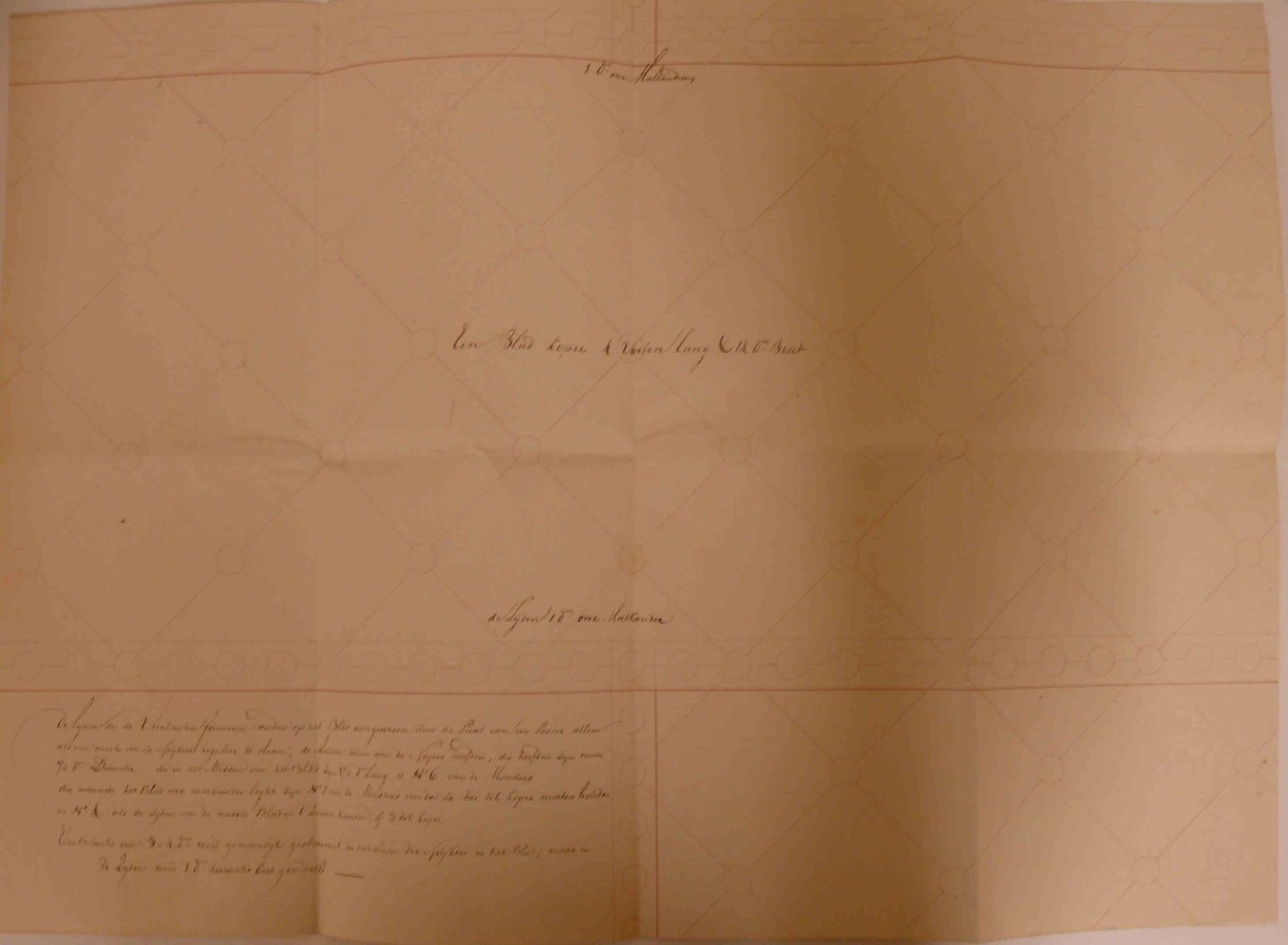
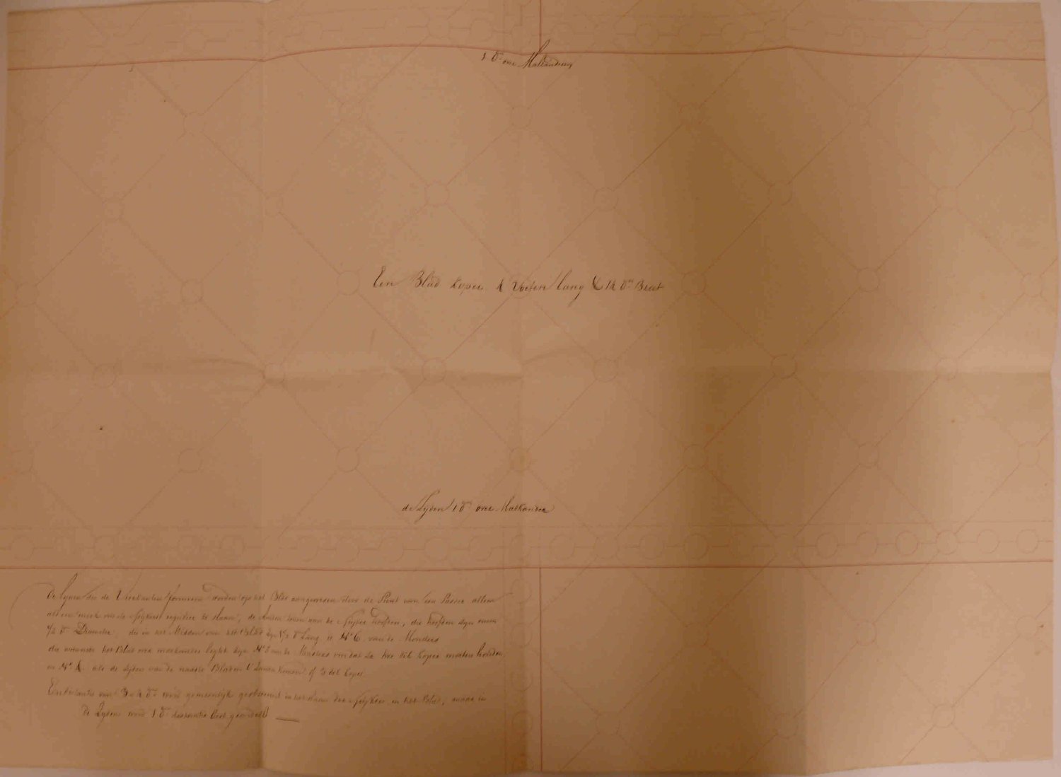
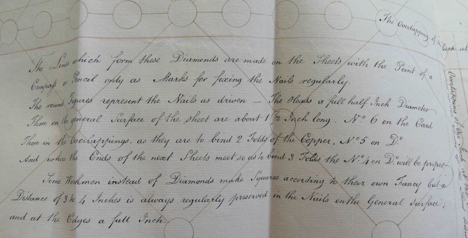
Nationaal archief Den Haag - Zugangsnummer: 1.01.47.29, Inv. Nr. 15 von ca. 1780. Die Platten waren 4 Fuß lang und 14 Daumen breit. Die Überlappung betrug 1 Daumen. Amsterdamer Maß. 1 Fuß 283 mm, ein Daumen 25,727.. mm. (Thanks to Werner) My interpretation of the thicker red line is that the upper overlaps the lower plate
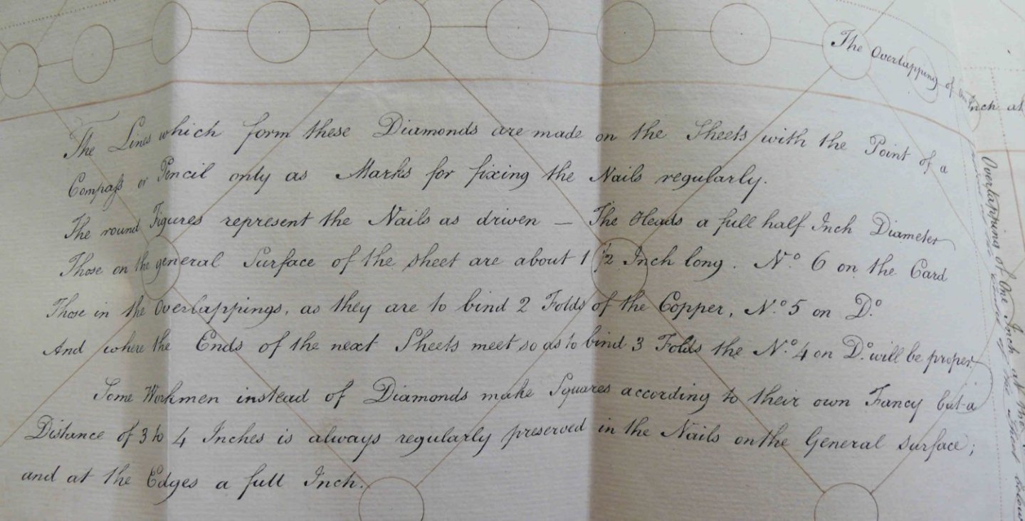
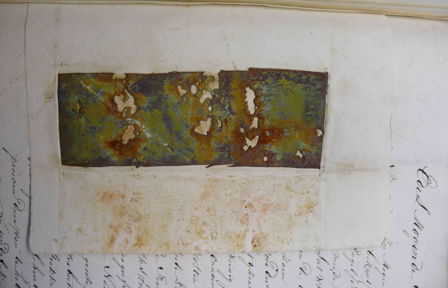
This could be an english original for the drawing above. Even with a copper sample 🙂
Nationaal archief Den Haag, Zugangsnummer 1.01.47.21 - Inv. Nr.: 112.

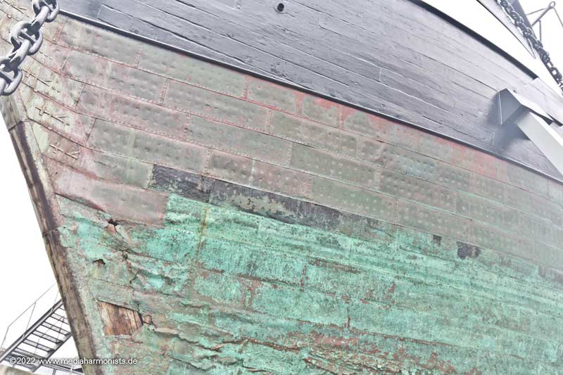
San Francisco Maritime, National Historical Park, California, On permanent exhibit in the Maritime Museum is a portion of the hull and the rudder of the ship NIANTIC, which was beached at Montgomery Street during the Gold Rush and become a store and hotel. The vessel housed the boot shop of abolitionists.
Intersting that the fittings on the hull were overplated, the fittings of the rudder were not ...

Cutty Sark in 1872 after she lost her rudder, lower one over the upper one


Historical picture of the Victory, lower over upper

Just see how evenly it was layied 😉 Just like St. George´s copper.

Not contemporary but nicely to be seen on Constitution 😉

Jyland, were old meets new.
And for those who like films 🙂
Boston Tea Party Tours - Copper Cladding Begins | #11
https://www.youtube.com/watch?v=6TP5qGce...E78C06557ABDA9B
Boston Tea Party Tours - More Copper Ship Cladding | #13
https://www.youtube.com/watch?v=YpVQ-EIGZW4
Boston Tea Party Museums - Copper Cladding | #17
https://www.youtube.com/watch?v=vZdH-r5a_HQ
Boston Tea Party Museums - Fitting The Rudder | #18
https://www.youtube.com/watch?v=AO4uwCVIhwA
Boston Tea Party Museums - Damaged Beaver | #19
https://www.youtube.com/watch?v=dcL2yVlri-w- Sizzolo, Knocklouder, Blue Ensign and 3 others
-
5
-
 1
1
-
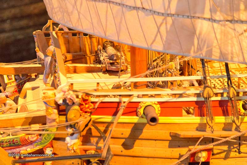
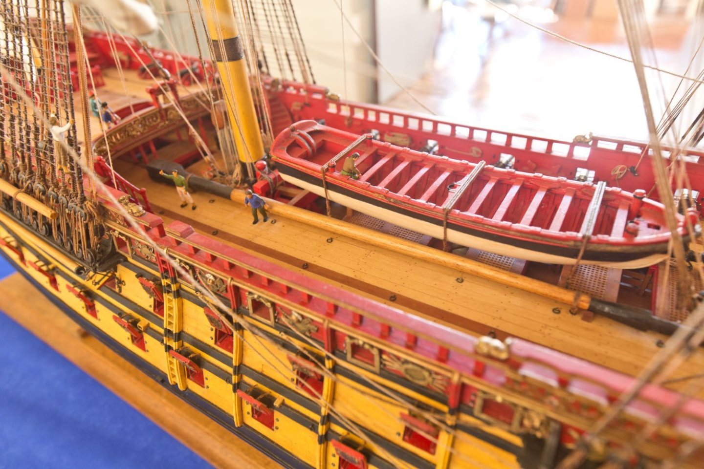
The question I am having is: Did in Soleil´s days those ports were pointing foreward or aft as seen in Vasa?
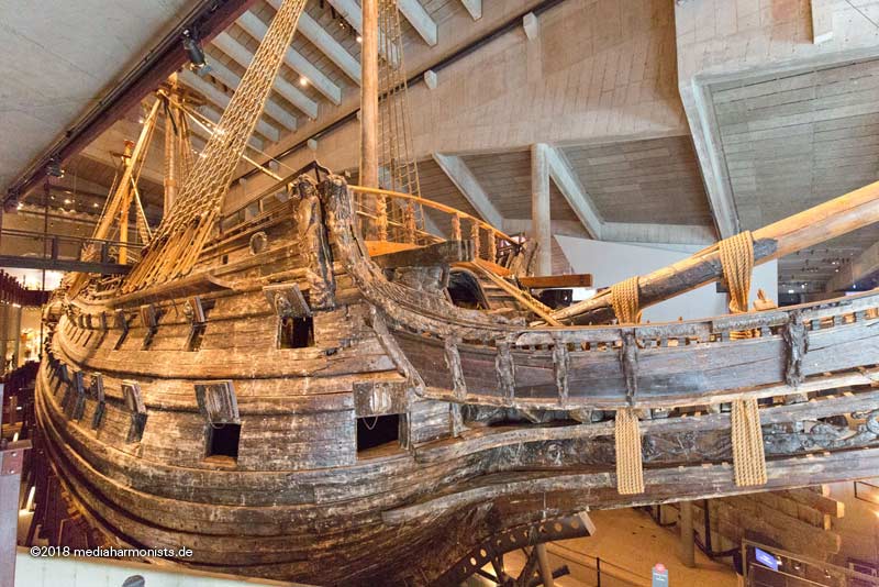
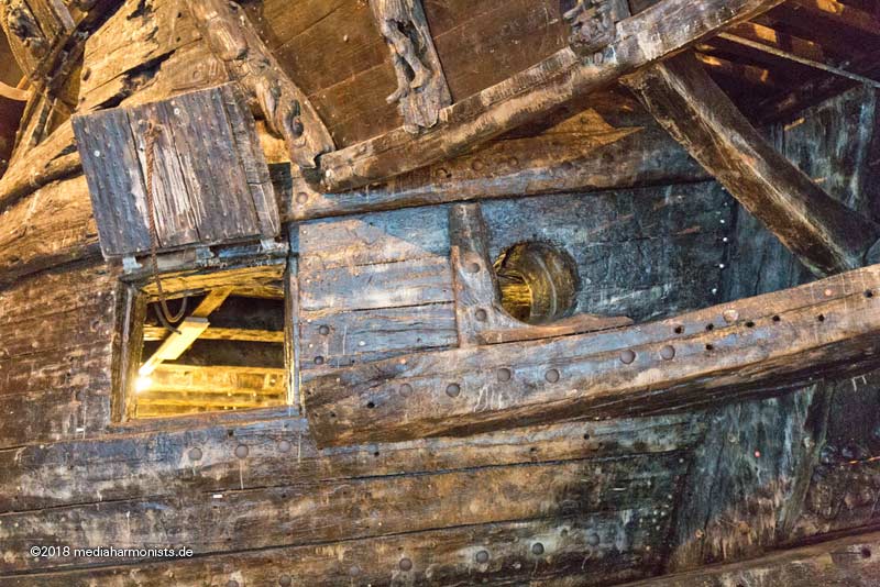
... and the 2 last ports each deck are pointing aft.
Nicely to be seen in the small reconstruction of the upper gundeck. Those guns can hardly be pointed the conventional way with 90° to the ship´s center line
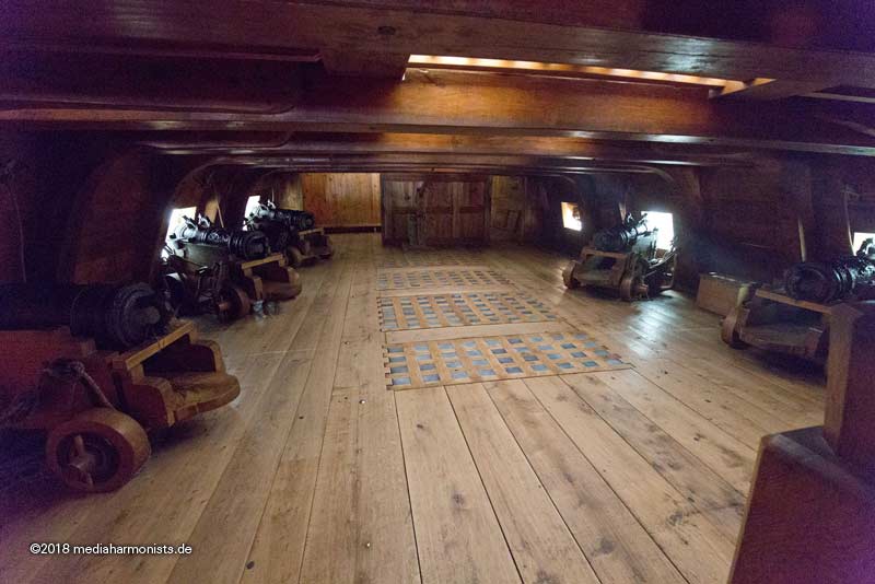
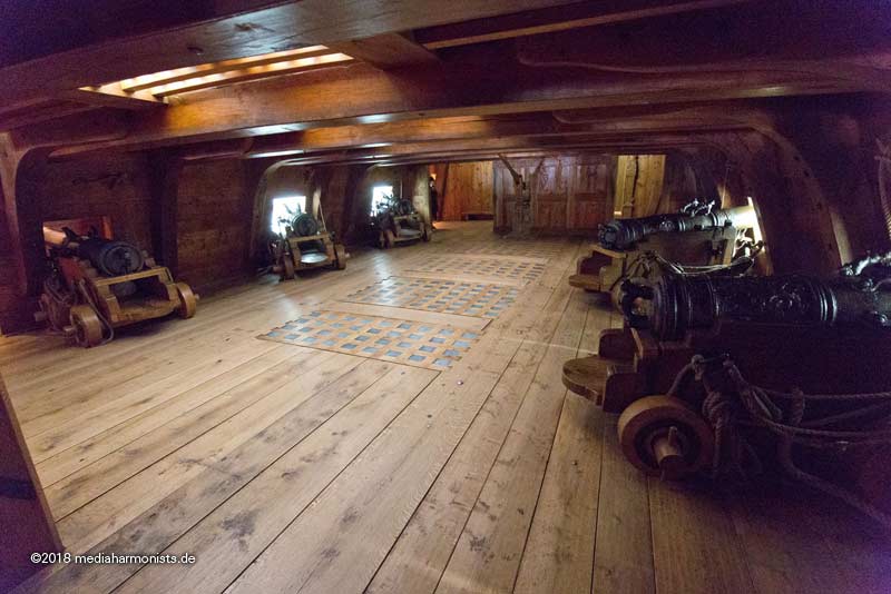
Also on "head chasers" on the upper deck are pointing forewards.
... thus avoiding the cathead-knee 🙂
Something that went wrong on the 1:10 model, where these guns have to be placed over the cathead-knees 😉
By the way, the lower deck guns have the same errata.
XXXDAn -
Hello William,
you always will have sources that seem to contradict each other. Usually it is just a question of timing 🙂
Even I do always struggle ...
The solution there is quite similar to both Longridge and McKay, Peterssen is missing one boobstay as he treats a smaller vessel.
Does this help?
XXXDAn
PS: Always do it with your heart(s) 😉
-
On 12/12/2021 at 12:07 AM, Kevin-the-lubber said:
Meanwhile, a couple of pics of todays 'R&D' between weekend jobs. Staggered lap joints to simulate joining hull sections; glued together with CA and a little light sanding to blend the joints. Once painted the lines would be quite faint and of course wood graining is optional (probably skip that, not least because it would be unbelievably tedious to do in the software). If the section joints were strategically placed to make use of gunport edges and more randomly staggered, I think you would need to know they were there to spot them.
.JPG.6bde5c9bfa0941cb9684d33d3d1f25b0.JPG)
.JPG.974c8173d1ba5751a0e62b0a08f06d36.JPG)
Very nice trials, thank you for showing.
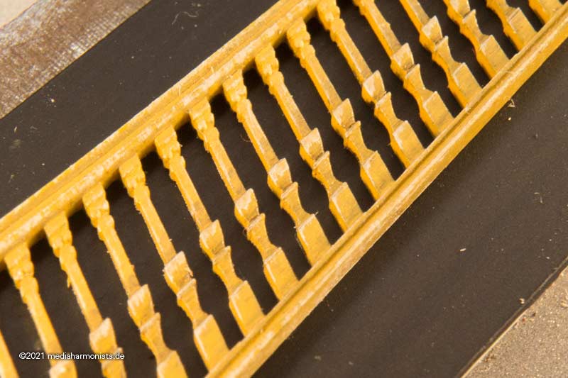
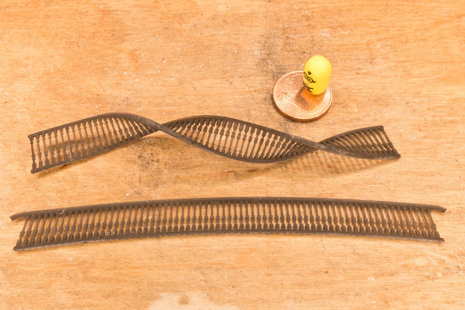
In the pictures can be seen a strong warping. I encountered this also occasionally. Still trying to get the reasons.One can be as for the minimal shrinking while curing either as for different amount of material on each side or more curing on one side than the other.
Do you remember if these parts were cured equally on both sides? Were they printed vertically or lying flat?
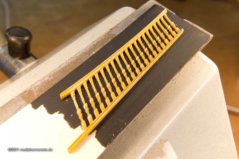
From experience I know that this can be mended with some warm water, it softens up the material and one can cool it down in the wanted form. How extreme this even workes is here with some ballusters from my samples that can really be twisted into a screw like form 🙂
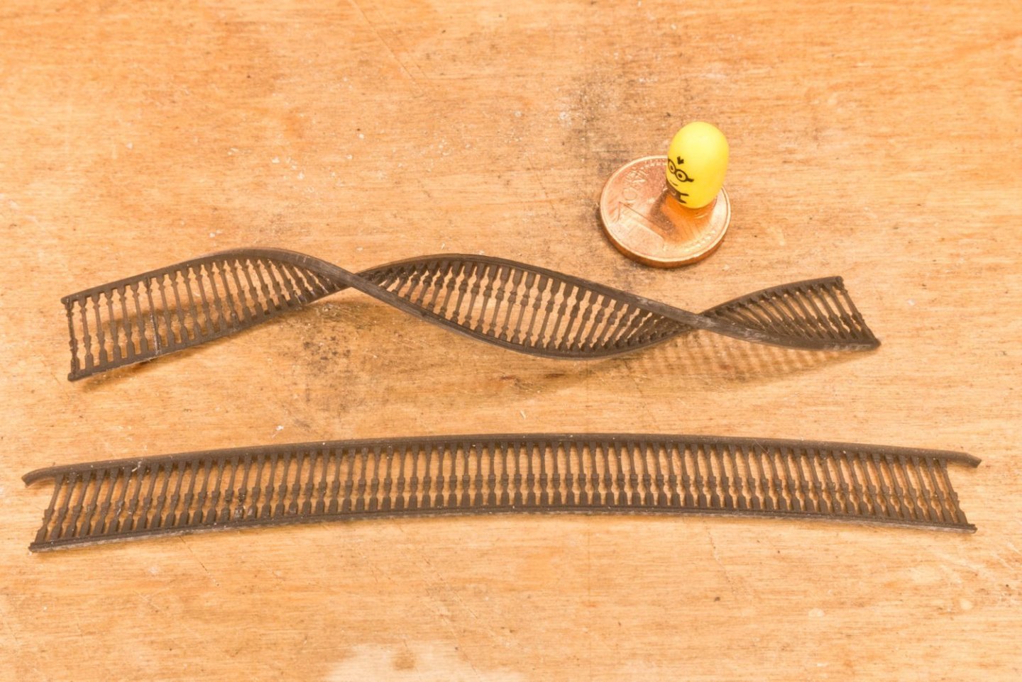
This means never bent a cold resin part (either print or "classic" cast) but always have a cup of hot tea first and warm it up in there 🙂

- normal hot water also works 😉
XXXDAn
- Mexspur, Archi and William-Victory
-
3
-
16 hours ago, Kevin-the-lubber said:
To tell the truth, I was happy enough just to get away with airbrushing the yellow ochre and parked the project as soon as that was done. ... Anyway, sooner or later I’ll pick up on the stern again and will probably experiment with some shading.
Just go for it it really is worth a try, adds enormous for the appearence and is not too difficult!
Here are the test shots from my build, first the ink to create deapth, then a bit of white brush and the things are alive 🙂
XXXDAn
-
13 hours ago, William-Victory said:
Disregarding my studies in ‘Dafinology’ ...
🤣🤣🤣
You could carefully try to press the grating upwards. If not too much glue is involved it should be possible.
XXXDAn
-
-
Hello Eric,
to avoid friction, the tube should be pointing downwards 🙂
Anyway I do not know, if at that time this protection was already invented. I believe you can easily skip it.
And just to confuse you even more, the monograhy from Gerad Delacroix "The SAINT-Philippe 1693-1715" shows two lanyards, but that was a tad later build. Here a picture that I took on the exhibition in Rochefort in 2018.
Also have a look here at the gods of french arsenal building:
https://5500.forumactif.org/f92-le-saint-philippe-1693-1715-plans-jean-claude-lemineur
https://5500.forumactif.org/f11-le-vaisseau-de-colbert-1670-plans-anonymes
https://5500.forumactif.org/f31-la-renommee-1744-plans-jean-boudriot
-
Hello Eric, very nice start 🙂
Ian is putting lot of confidence in my knowledge, but I think Hubac is much closer to this time frame than me with my Victory.
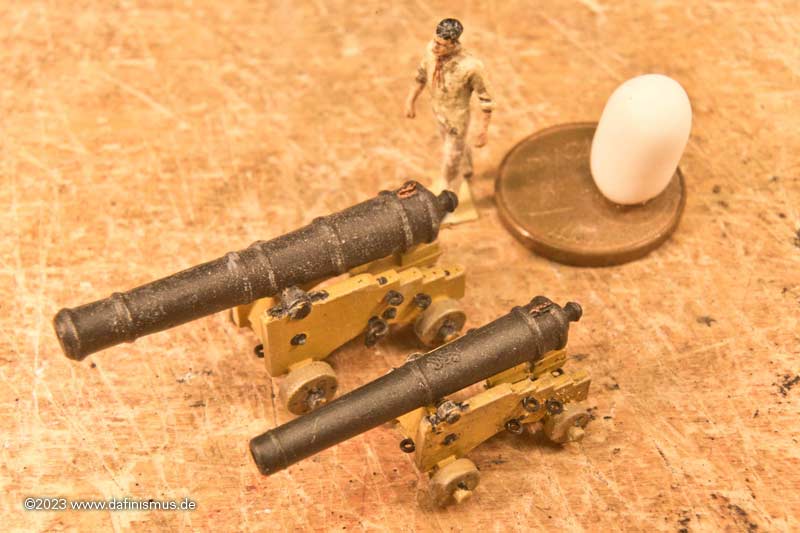
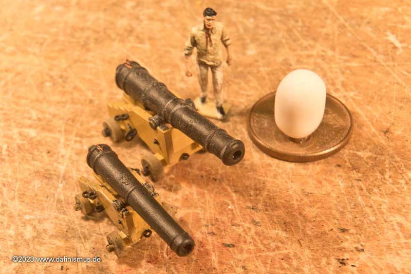
Here is the aforementioned change of the guns: Trunnions more to the back and axxis more apart, It immediately looses the "toygun"-flair 😉
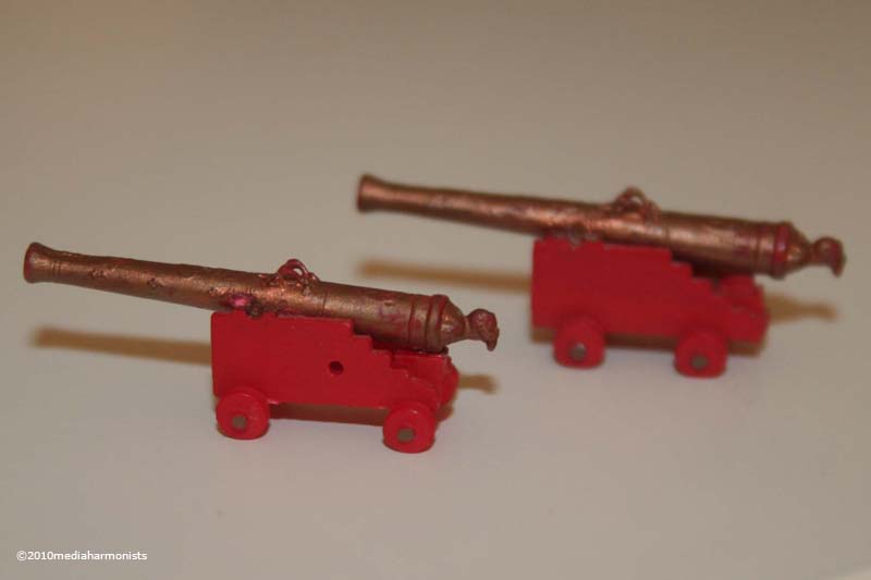
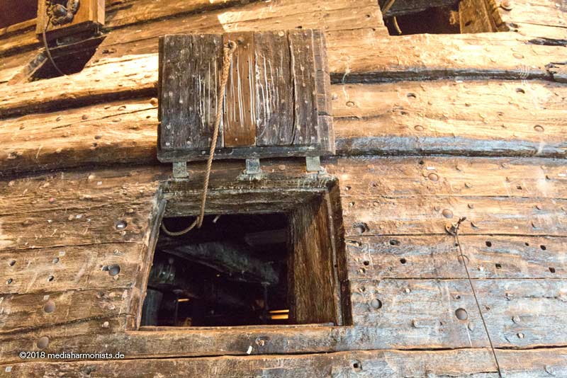
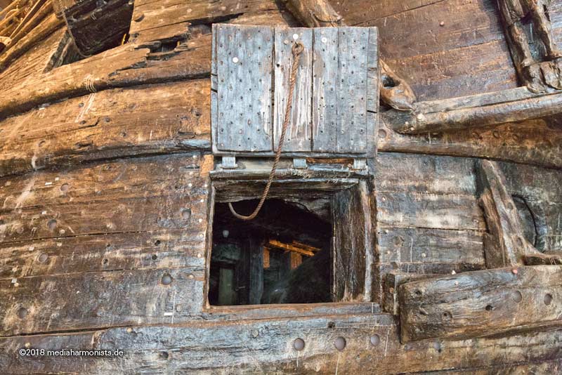
As for the pot lids, it was still common at this timeframe just to have 1 lanyard, when they actually changed to 2 I am not sure. And if Soleil was equipped with 2 I know even less 🙂
Some hints are given by the "adaptation of SR’s sister ship La Reyne into Soleil Royal" of Hubac´s last post, only showing one ring on the bottom side and the contemporary (HMS) Prince´s contemporary model that also only shows one lanyard per gunport.
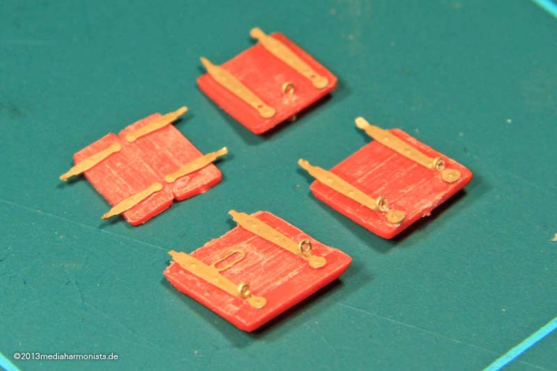
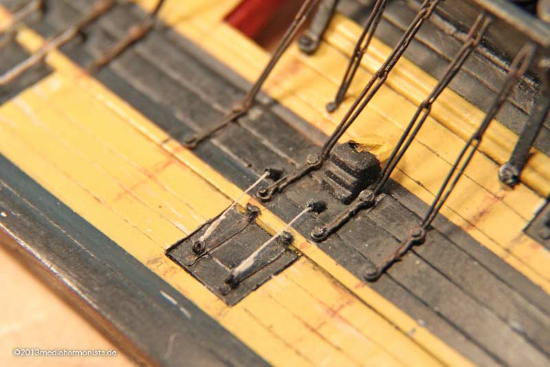
But if you use 2 lanyards the rings were usually fastened at the end of the metal strips and not inbetween. See the gunport fittings of my Victory. And you also see that even in those later days the smaller gunports also had only 1 lanyard 🙂
More about this topic here:
Also I used two brass wires to fox the lid to the hulll, this enabling a small gap, here a early version.
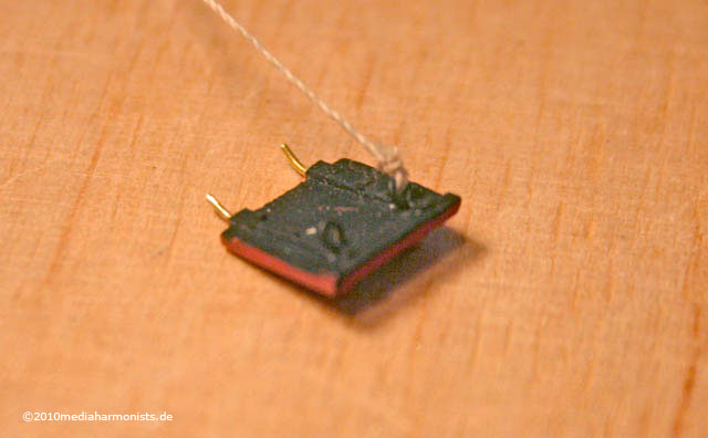
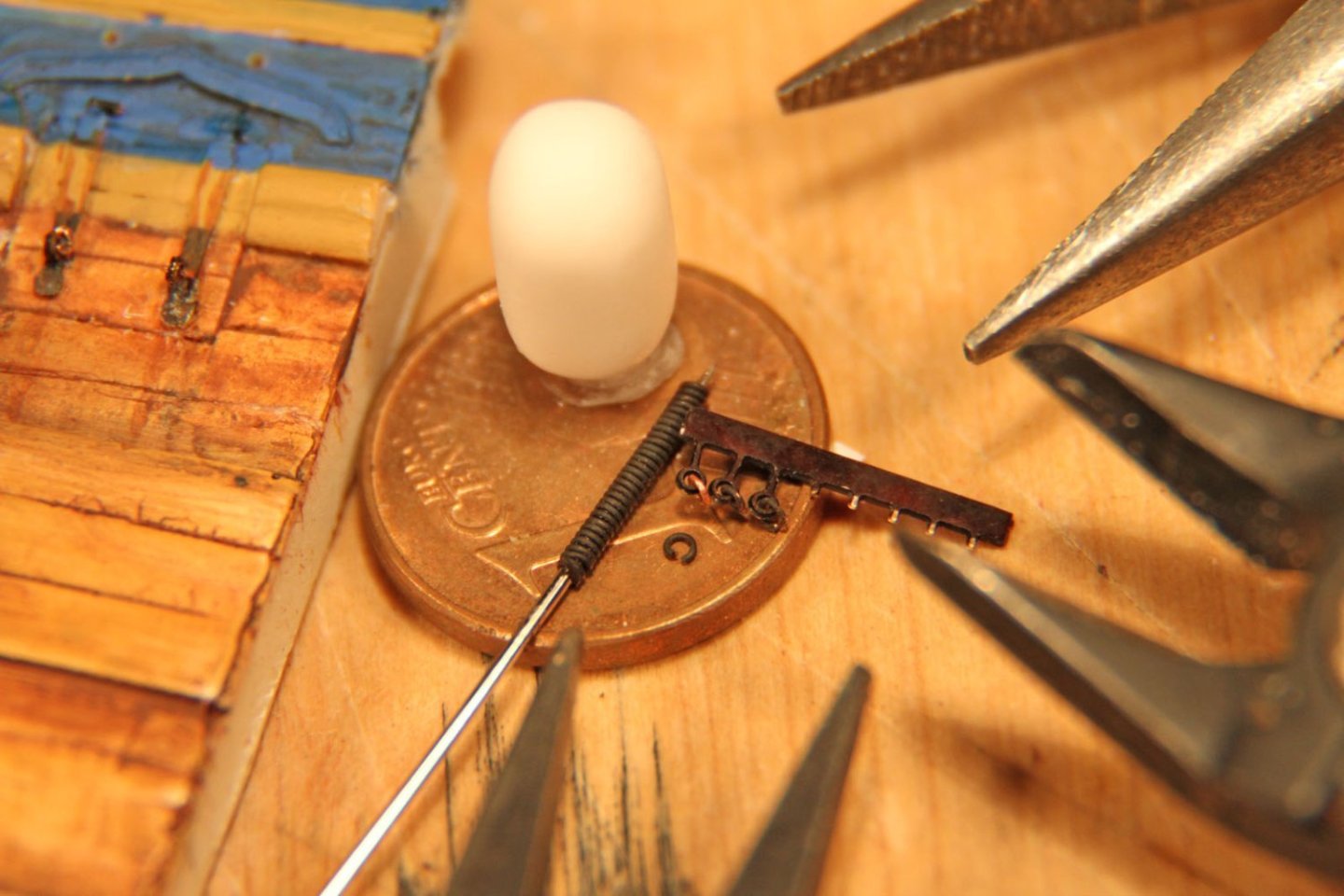
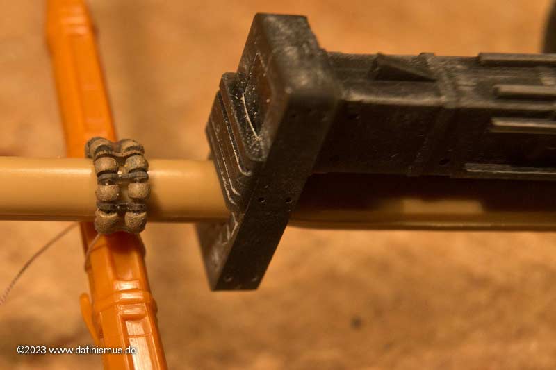
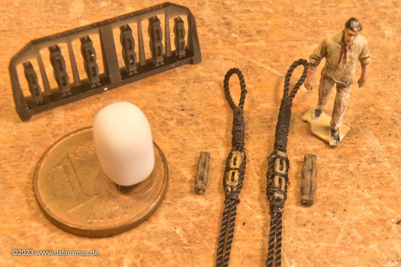
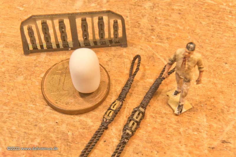
Together with the small eyebolts from my sets this should look like the following pictures. This should give you the scale of the ensemble of the eyebolts and the according rings, be it 1 or 2 lanyards. First one of implementing the rings onto the eyebolts, second the finished lanyard with leather protection for the inlet hole that was made out of bored out and pulled sprue 🙂
Hope this helps, DAniel
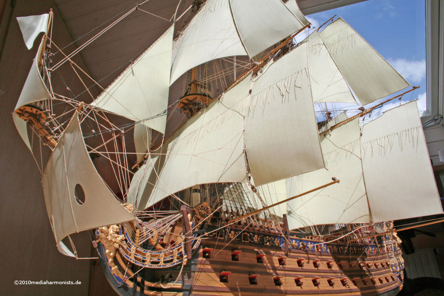
Just to round up, here a picture of my rendition, also a restart after almost 30 years of tinkering abstinence 🙂
- Bill Morrison, GrandpaPhil, Ian_Grant and 2 others
-
4
-
 1
1
-
Thank you Sirs!
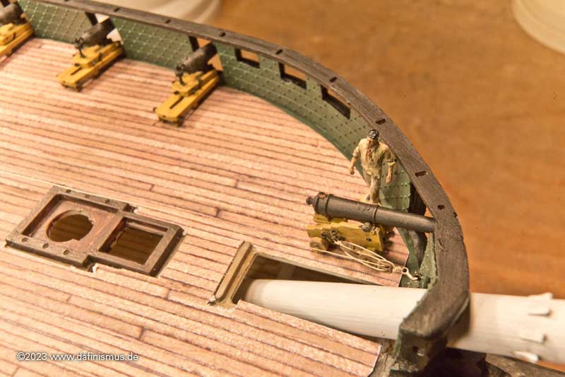
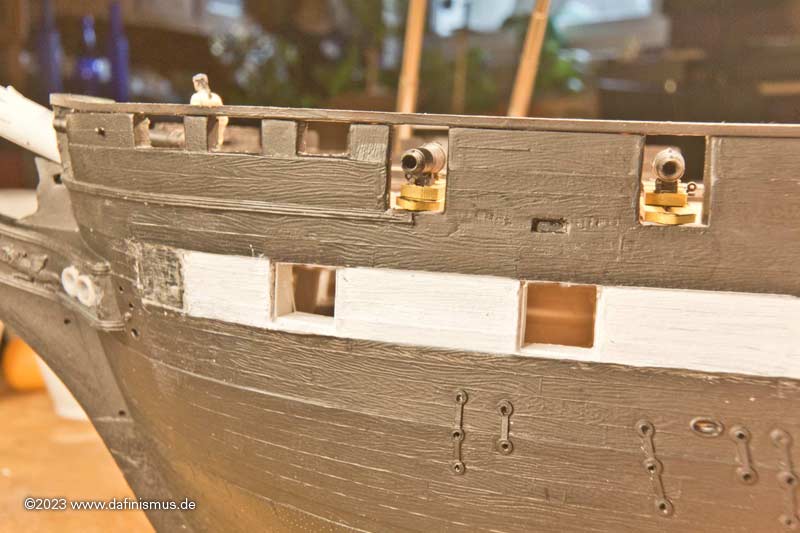
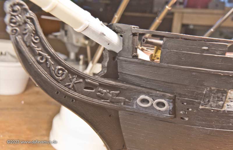
Somehow it was time to do something to this little USS chick again. The infamous gunnade in the bow was still missing.
Even if it has already been questioned, I decided in favour of the variant with the GRIII crest.
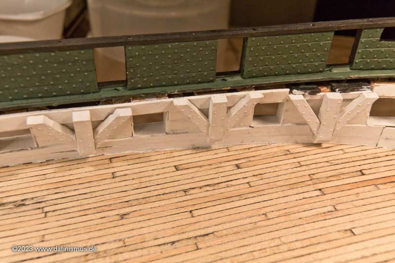
Then I prepared the space on deck for it, fitted the lower deck knees and printed the nailed interior bulkward ...
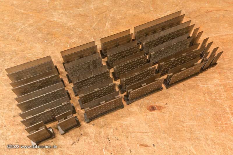
... and glued it in.
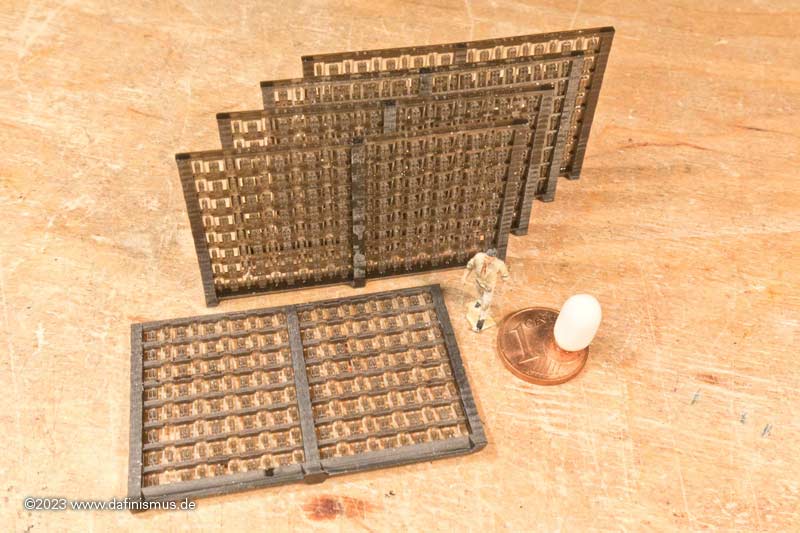
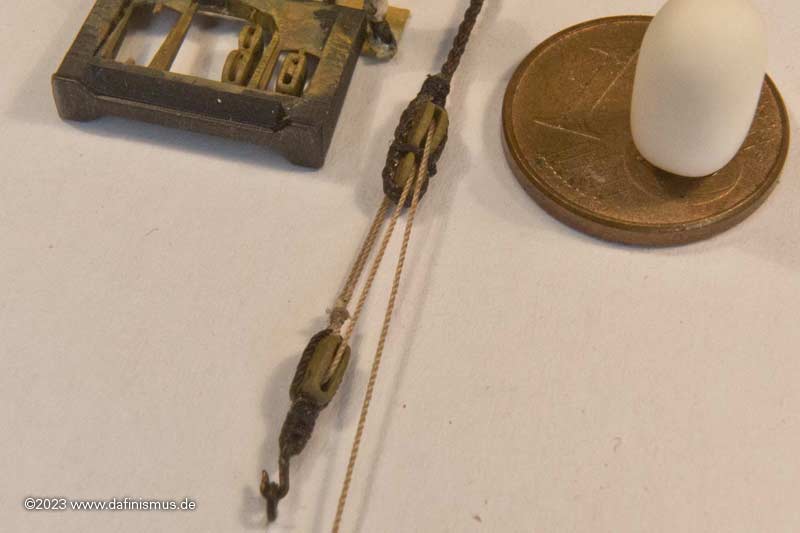
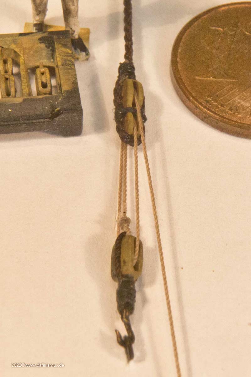
Then checked the size of the blocks. The 2.5 mm were too long after all.
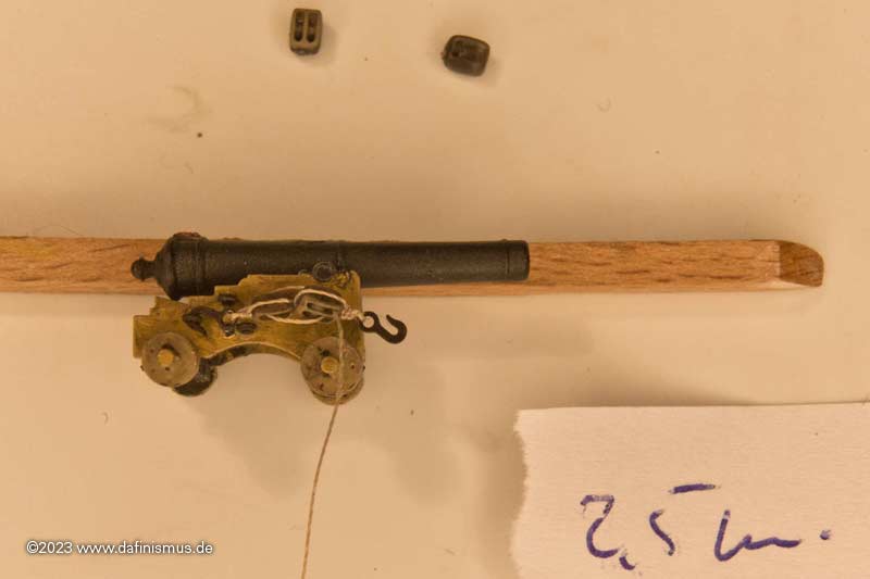
So it became the 2 mm blocks 🙂
I now also have a technique that works quite well. You sharpen a toothpick well ...
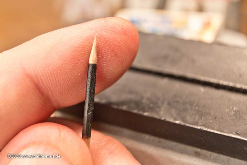
... and clamp it in a vice.
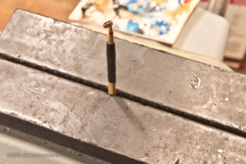
Then put a piece of paper over it to make it easier to see, and press the block onto the tip.
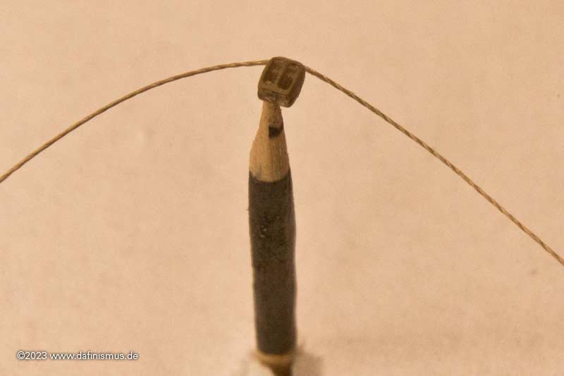
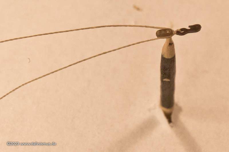
First check which side you need to start on so that the rolls are on the right side. Then apply 2 mm of superglue to the yarn and press it onto the correct side, ...
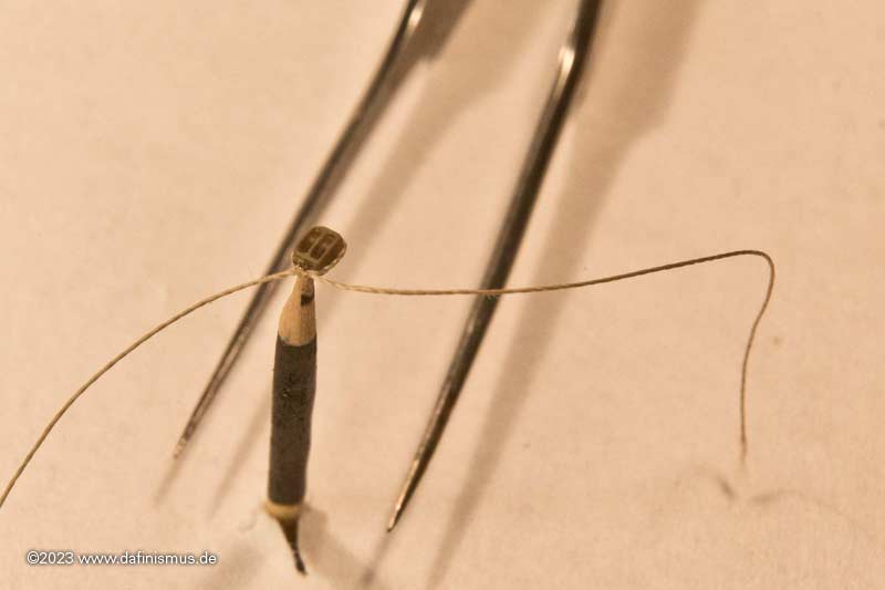
... pull the ends forwards, tie a knot and secure with glue. Then knot the hook, secure it, cut it to length and the double block is finished.
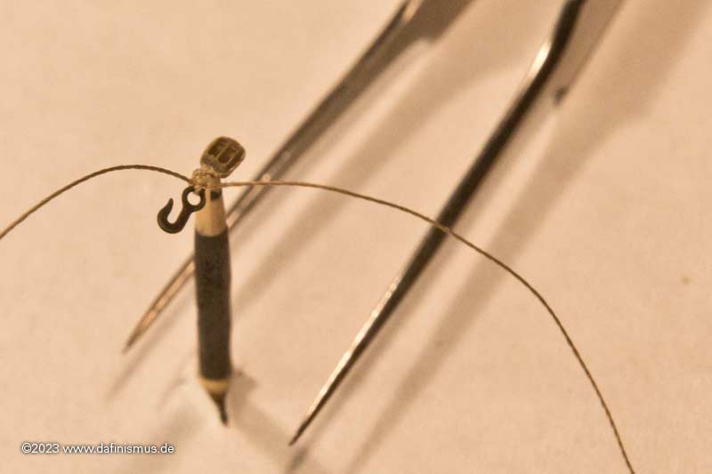
For the single block, first knot in a hook, apply some superglue to the hook´s knot ...
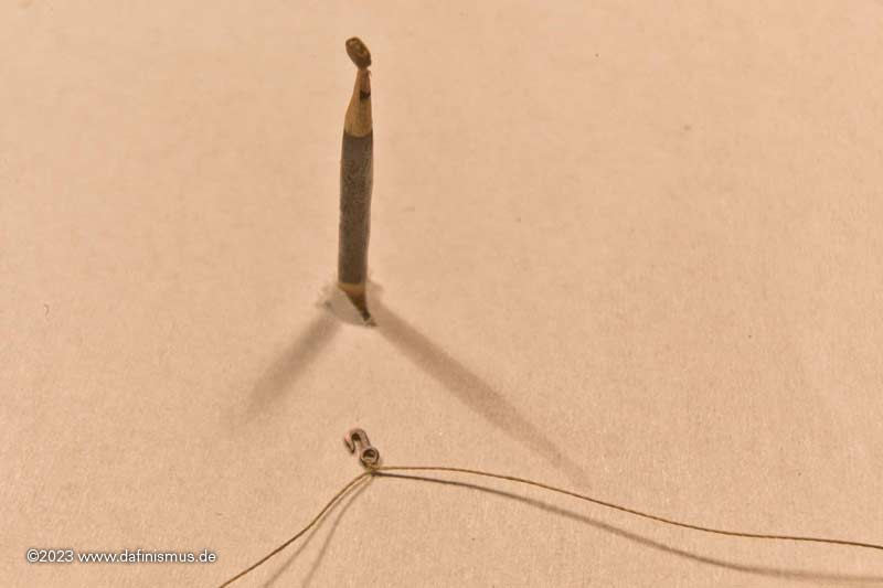
... and as with the other one ...
... with a little superglue at the back and tighten the ends to the front.
Then tie a knot, secure and cut to length.
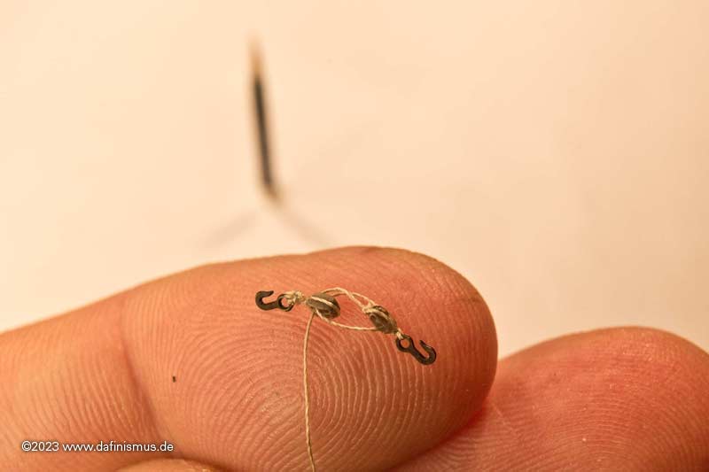
Now comes the most difficult part in my eyes: the correct run through the blocks so that nothing crosses over 🙂
And that's it.
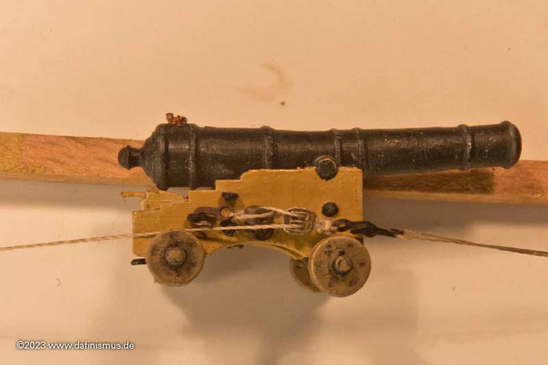
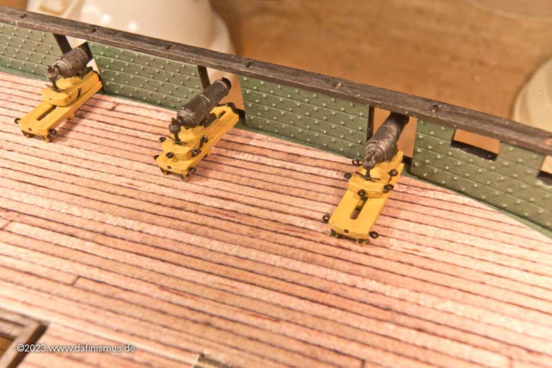
It also looks good on the 24-pounder 🙂
And then it was time for the trial fitting.
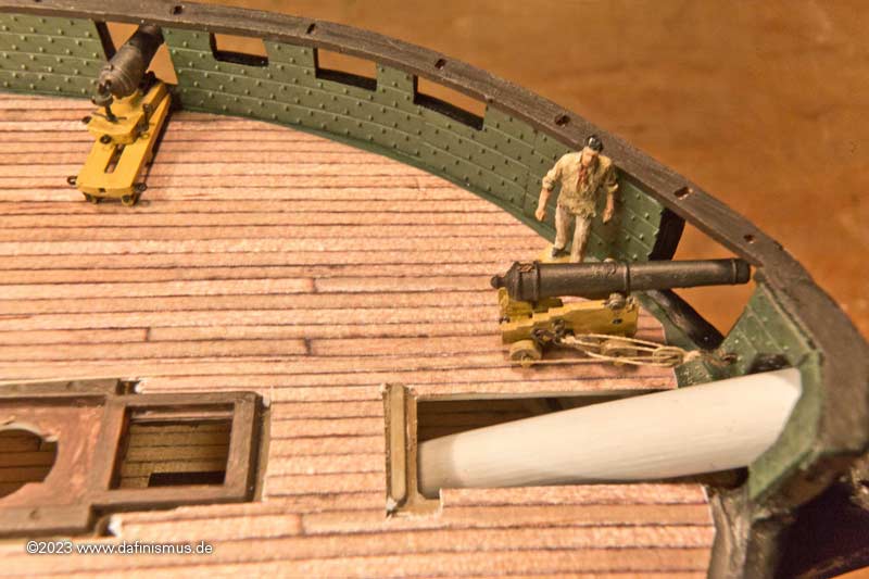
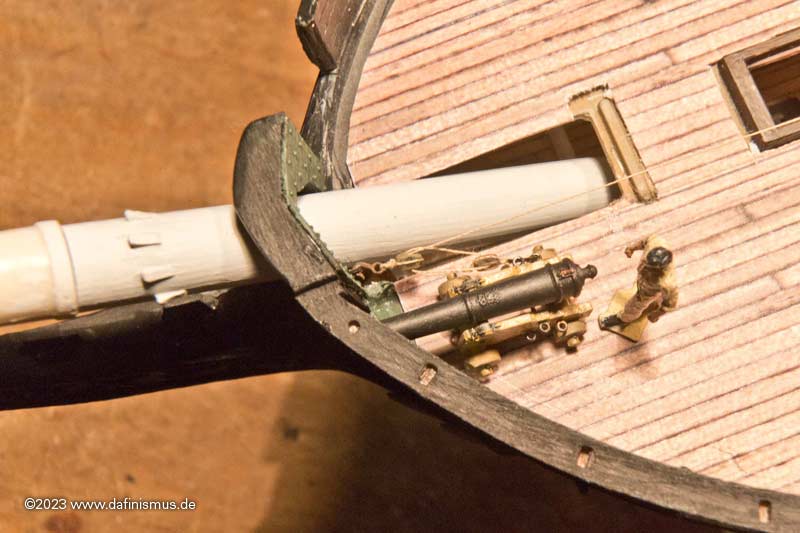
XXXDAn -
Once upon a time ...
The dafi had its annual public tinkering session with its modelling club at the Stuttgart trade fair. Then we went straight from the trade fair to a customer in Austria for a while. I didn't have a chance to think about anything model-building-related.
I'm back home now, and I can only catch up on what I've been doing over the last two months. But first things first 🙂
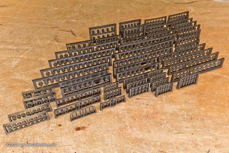
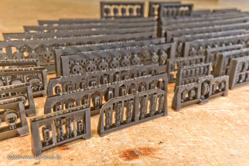
Before the trade fair, I had finished the running rigging. I wanted to try it out at the fair to see if it would be manageable, as the stuff - if true to scale - is very, very small.
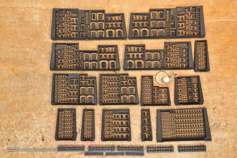
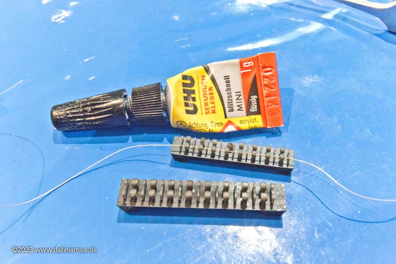
As with the standing rigging, I have summarised the block sets for the individual locations.
Here are the yards of the main mast ...
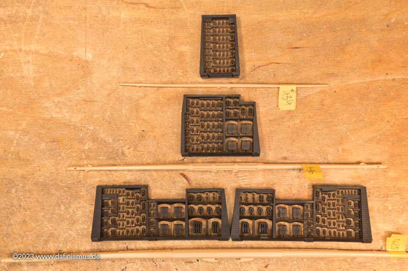
... of the foremast ...
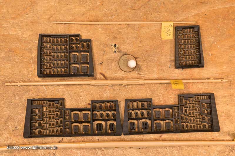
... and the mizzen mast.
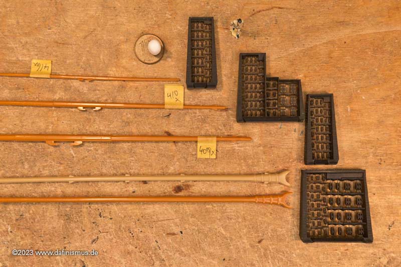
There are also the collections for headsails, stunsails and other locations.
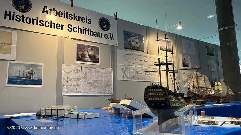
It was fun again at the trade fair.
Our booth ...
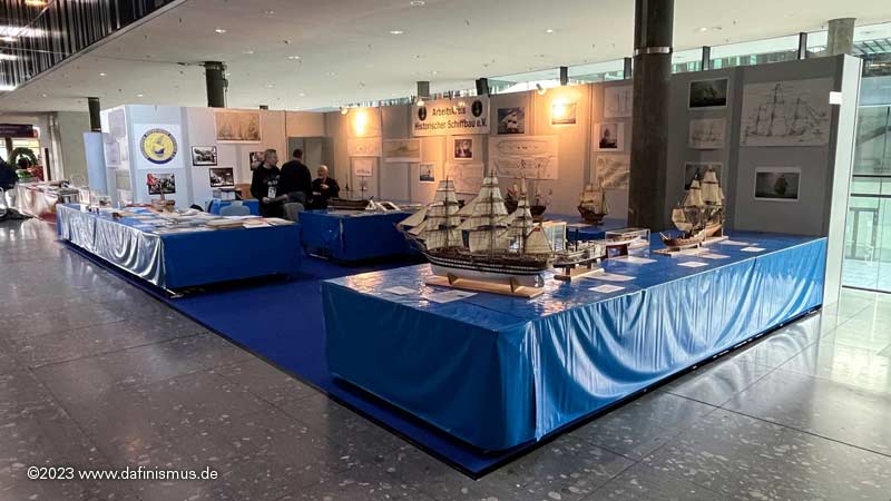
... my workplace ...
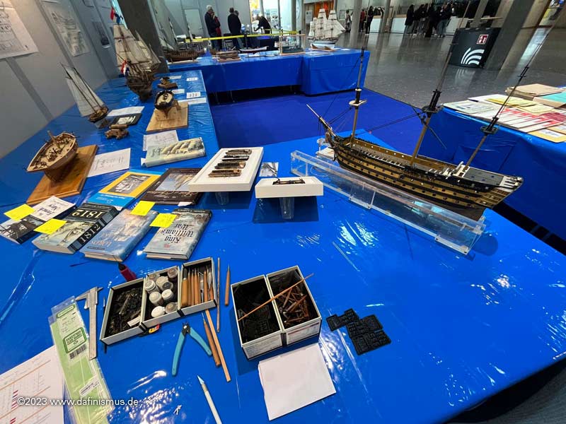
... and my colleagues in typical working posture 😉
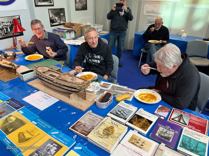
It was especially funny there when you want to try out the 2 mm blocks - the smallest of the sets - and don't have everything you need with you. Dear Alex then played vice and held my auxiliary jig for rigging - thanks for that!
It worked straight away and with my now tried and tested technique, even these small blocks are wonderfully quick and easy to rig.
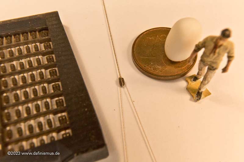
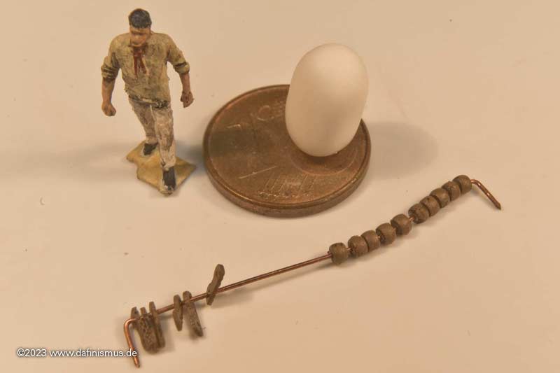
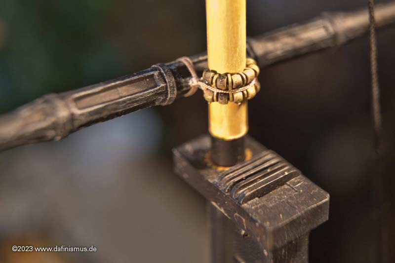
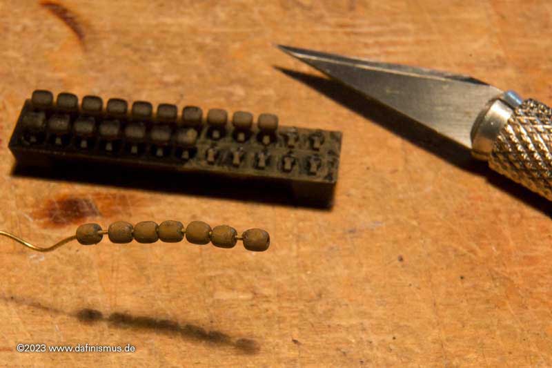
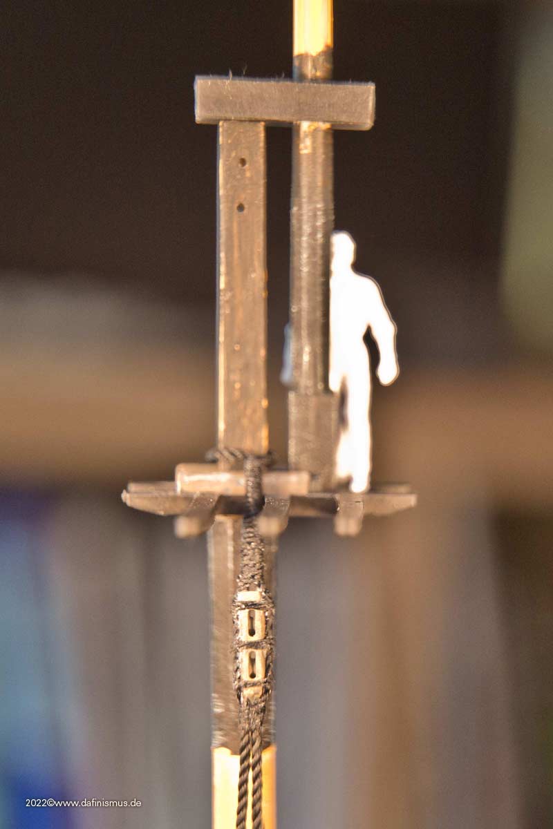
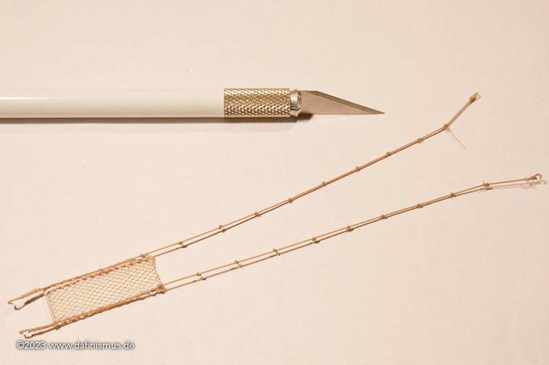
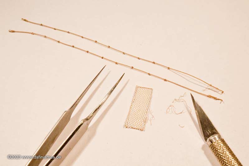
What was still missing were the parrells. I also managed to do this in a last-minute operation. Here are the two sizes with ribs for the top and topgallant yards.
Threaded for neatening ...
... and the first tying attempt to find out how many are needed.
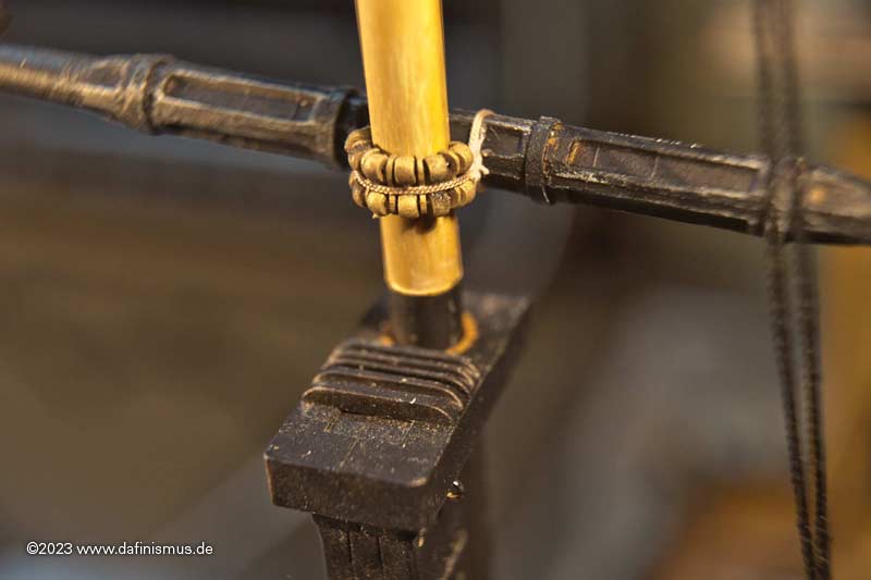
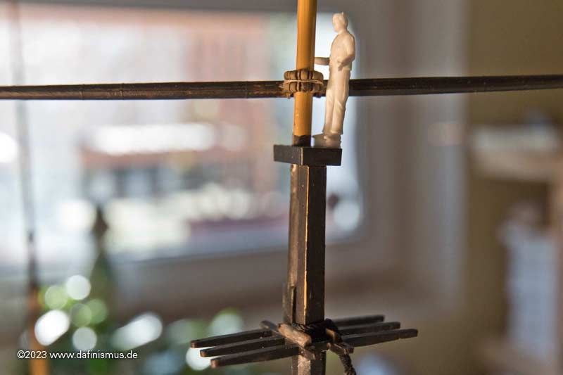
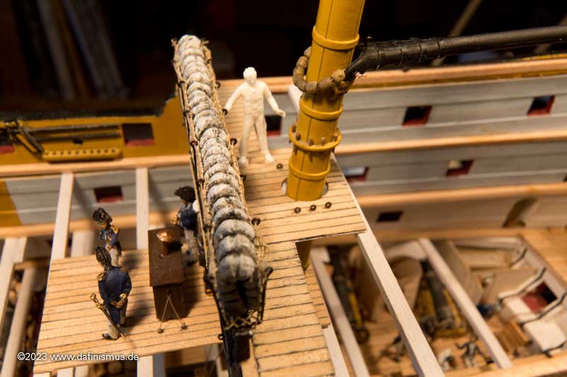
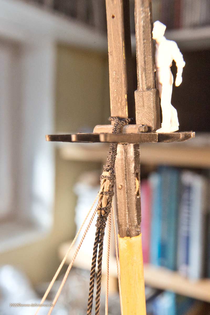
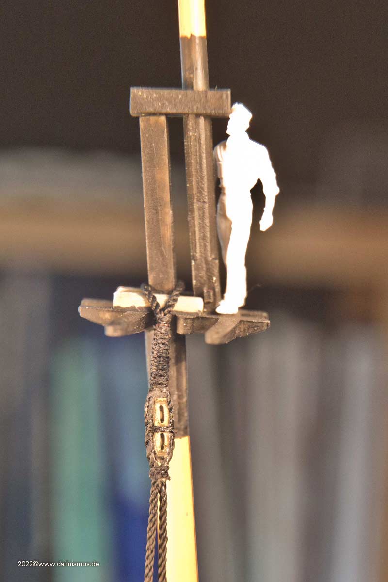
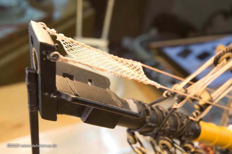
Here is the final version on the main top yard ...
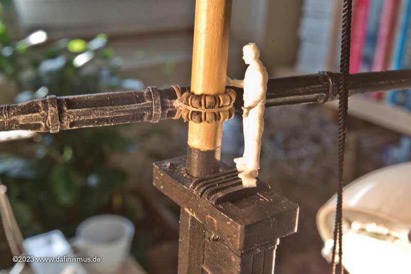
... and with a able seaman for the dimensions.
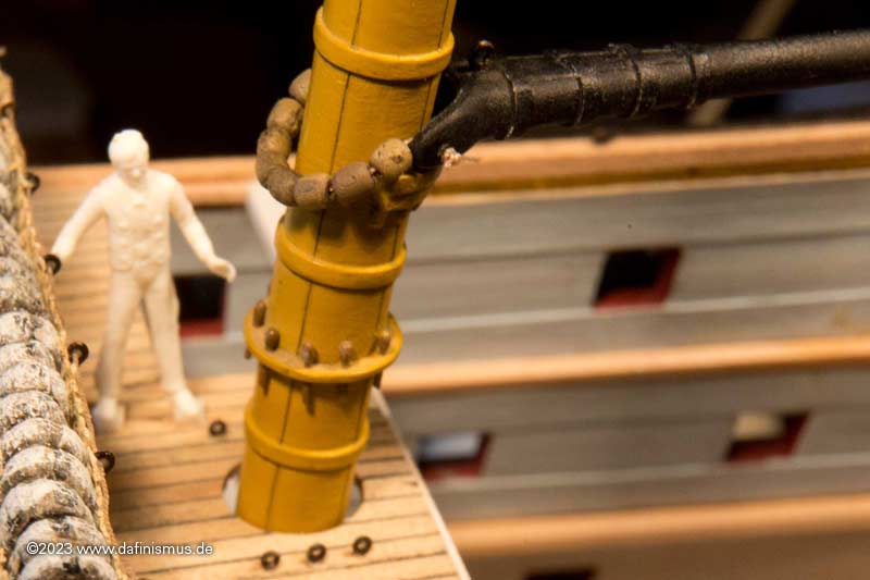
Someone also climbed up especially for the topgallant yard.
And to round things off, the stuff for the gaff also got their own size of parrells. First try ...
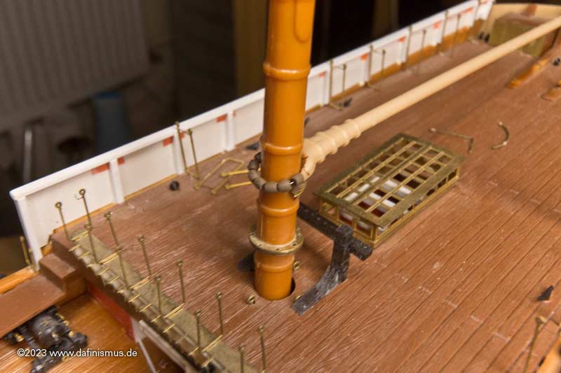
... the shape was adjusted a little and the final version is on its way.
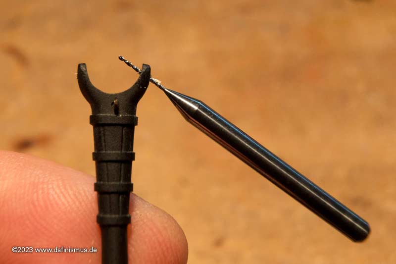
The claw is also grained with the centre punch ...
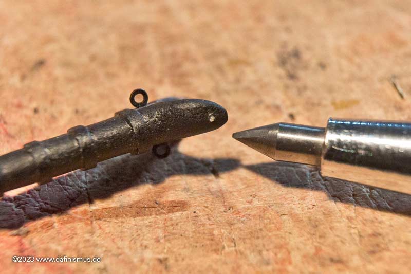
... and drilled out with 0.5 mm ...
... the blocks trimmed and wooded ...
... and into place ...
... and everything fits! Fits 🙂
Best regards, Daniel -
-
With the main yard I tried out the first blocks on the ship, and I really got into it with the hearts on the bow.
In the meantime it has developed further. It's amazing what a large amount came together for the standing rigging alone. Here is a family picture.
The special blocks were the most fun. Here are some in the foreground.
First the Sisterblocks, in German with the crisp name "Stengewantblocks", just try to speak that out loud.
Of course, the test assembly here on the main mast was exciting ...
... also with the matching ropes.
And also cute the smaller version on the mizzen mast.
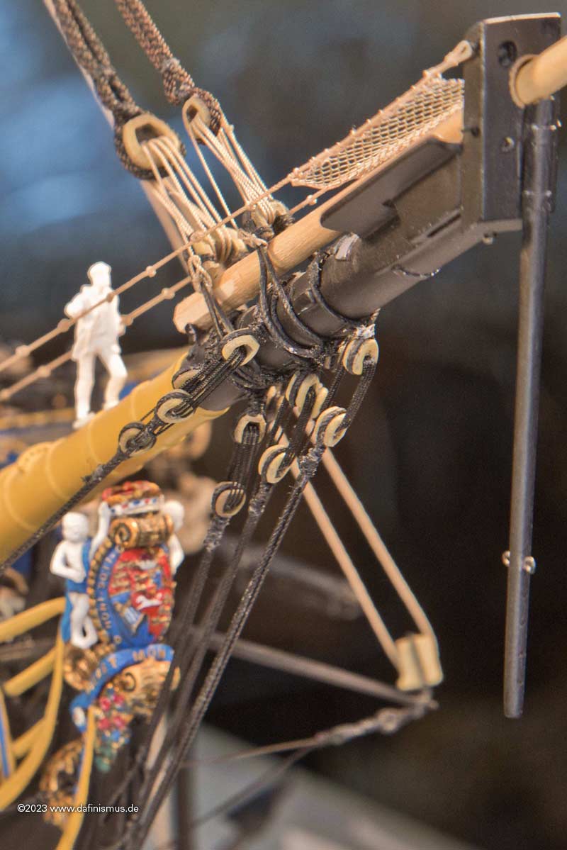
Long tackles blocks are used to stiffen the fore topmast stay and its preventer stay.
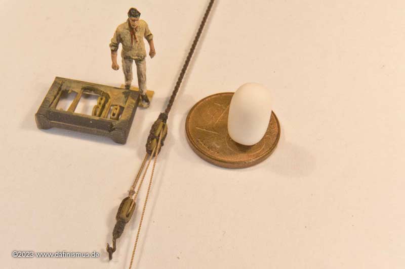
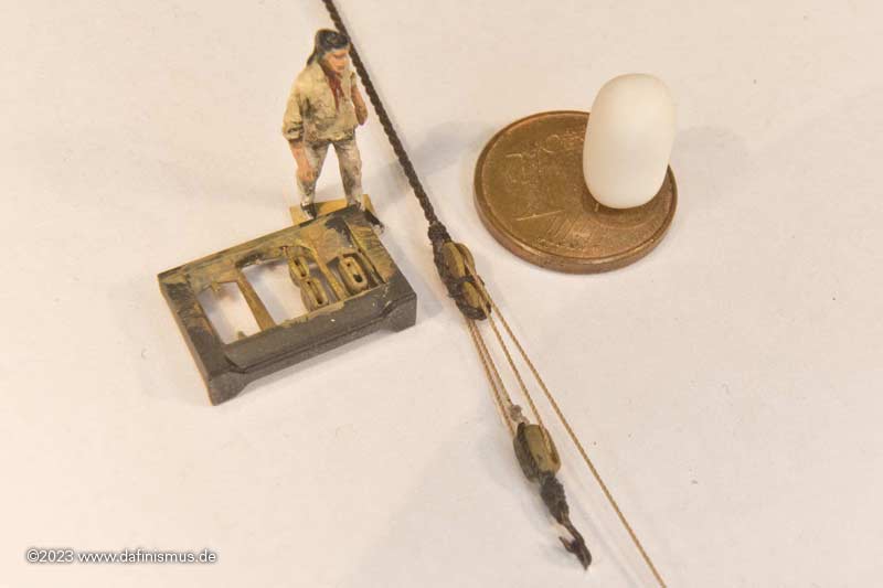
I'm also supposed to pass this in between the guys at the heads. Will also be exciting again.
XXXDAn -
-
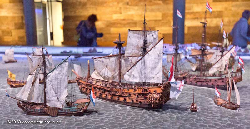
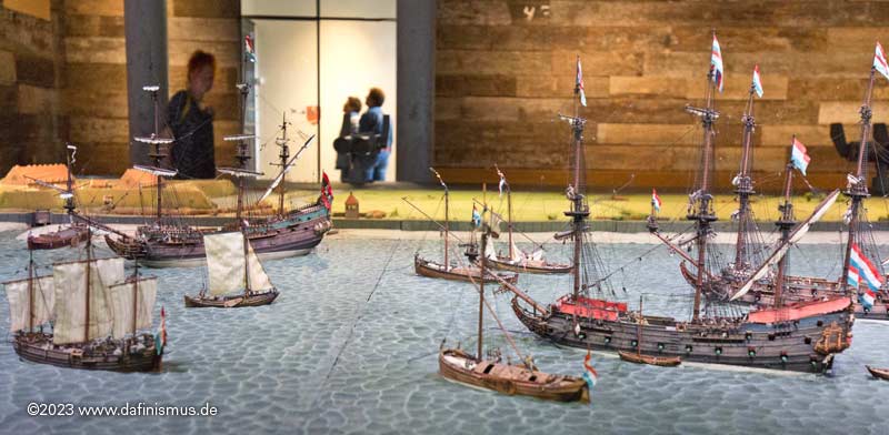
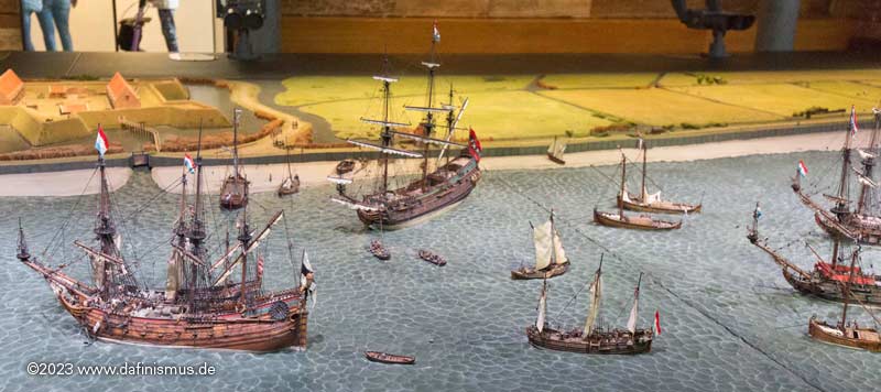
The models come from the company artitec and were made just for this model. I will post some more pictures soon :-)
Scale is 1:87.
What a pity that the pictures of Modellmarine have disappeared, they were very detailed.
XXXDAn
PS: I found a working Link to the pictures 🙂
https://www.modellmarine.de/index.php/fotogalerien/178-/1624-die-reede-von-texel-teil-2
- Mexspur, mtaylor and Veszett Roka
-
3
-
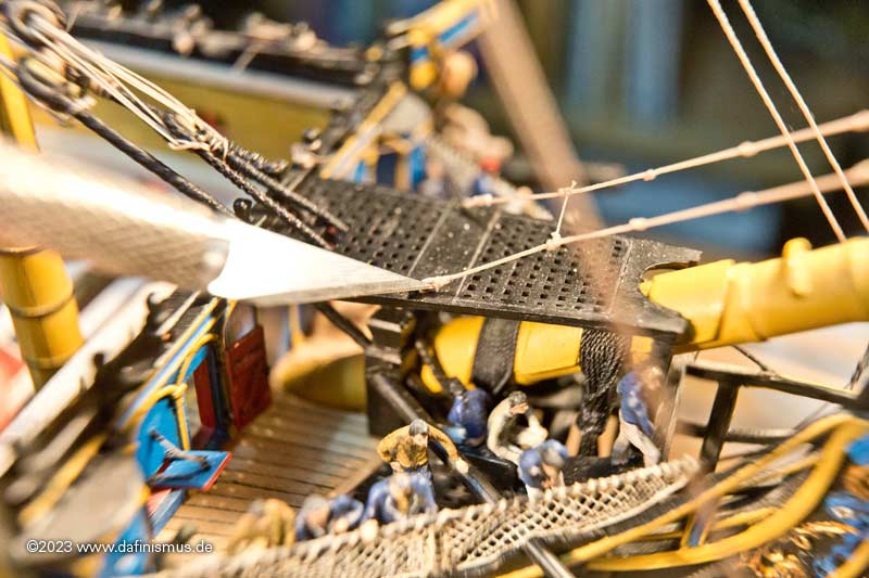
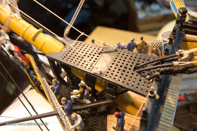
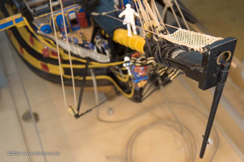
Elsewhere, people asked whether the net in front was not a hindrance and whether it would not make more sense underneath, as is the case today.
So I simply made some pictures that I don't want to withhold from yo 🙂
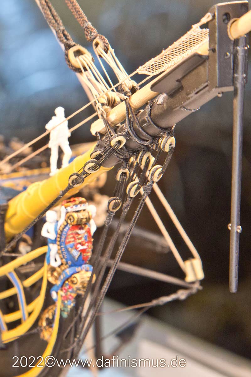
Here without the jib boom
And here with
You can see some things well.
- The wings of the bee give our little sailor a good foothold, which also explains the slanting position, which makes it easy to support oneself.
- The net is not particularly in the way, as you have to fish around the bowsprit cap in front of it anyway.
- The inner jib lands immediately in the net when it is brought down and does not lie over the spars. If it is stowed properly and successively when lowering, the standing area of our seamen also stays accessible.
- When the sail is stowed, the jib boom can still be moved.
What is also true, of course, is that this small net has evolved into the jib net we know today, where it has been reversed, because today you stand in the net and the sail rests on the boom. Even when stowing a medium-sized sail like the Hendrika, it takes a lot of strength to reach around and underneath the downhaul to fasten the sail. What was it like with the big sheets?
And the all-clear was also given elsewhere: In the literature, instead of the net, you always see two battens as a boundary at the top and bottom, connected with a zig-zag rope running lengthwise. Druxey gave me the hint that this was only a very short-term intermediate development stage that was very quickly replaced by the net. Thank you for that!
Sorry, so I don't have any more demolition for you today ....
XXXDAn- BLACK VIKING, druxey, popeye2sea and 8 others
-
11
-
This was the last status before Amsterdam ...
... and it came ...
... as it had to come ...
... demolition.
What had happened? While building the manropes, I noticed that some sources depicted them with knots and some without. My decision then ran through Lees and Marquardt, both with knots. However, this was a bit strange, since the knots usually only were there if the ropes were for the feet.
No sooner had I uploaded the pictures than druxey kindly pointed out that both Lees and Marquardt were exceptionally wrong here. After his hint on the contemporary indication of Steel I also found an identical passage in Rees: Outside with thimble in an eyebolt, inside with thimble and lanyard on eyebolt.
Ok I think, I possibly could get this right.
Outside.
Inside.
And as usual a climbing test.
And since the old picture was so nice and I couldn't get the light right, just a round of image processing and this one is right too 🙂
XXXDAn -
Starry sky, I dreamed of the starry sky ...

So the small box went into the big box ...
... and off to Het Scheepvaartmuseum in Amsterdam (Marine Museum Amsterdam).
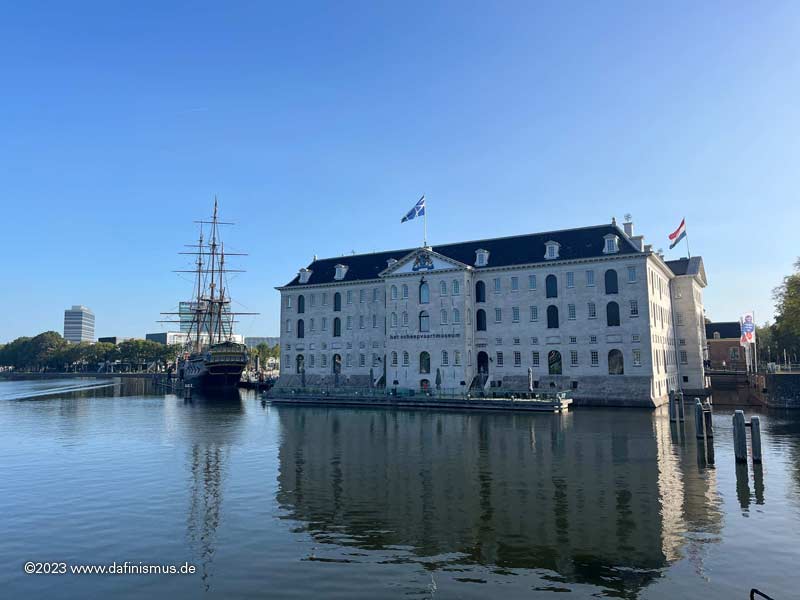
Holy Grounds - here we are 🙂
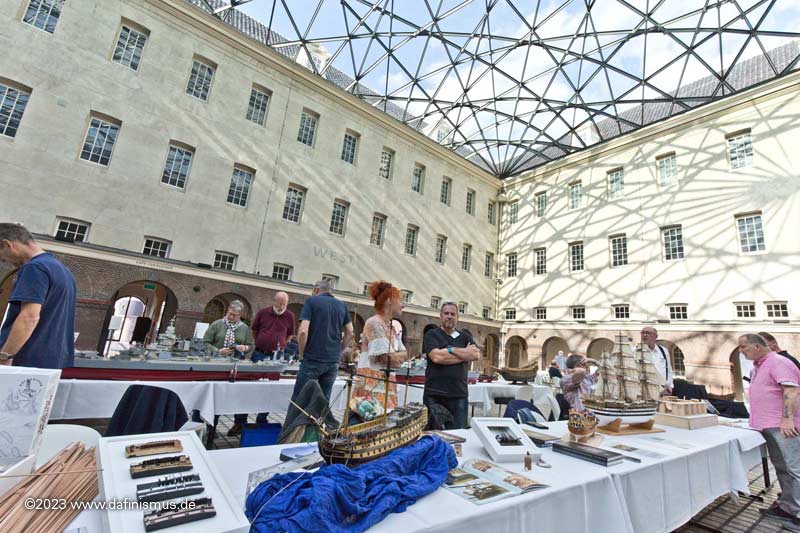
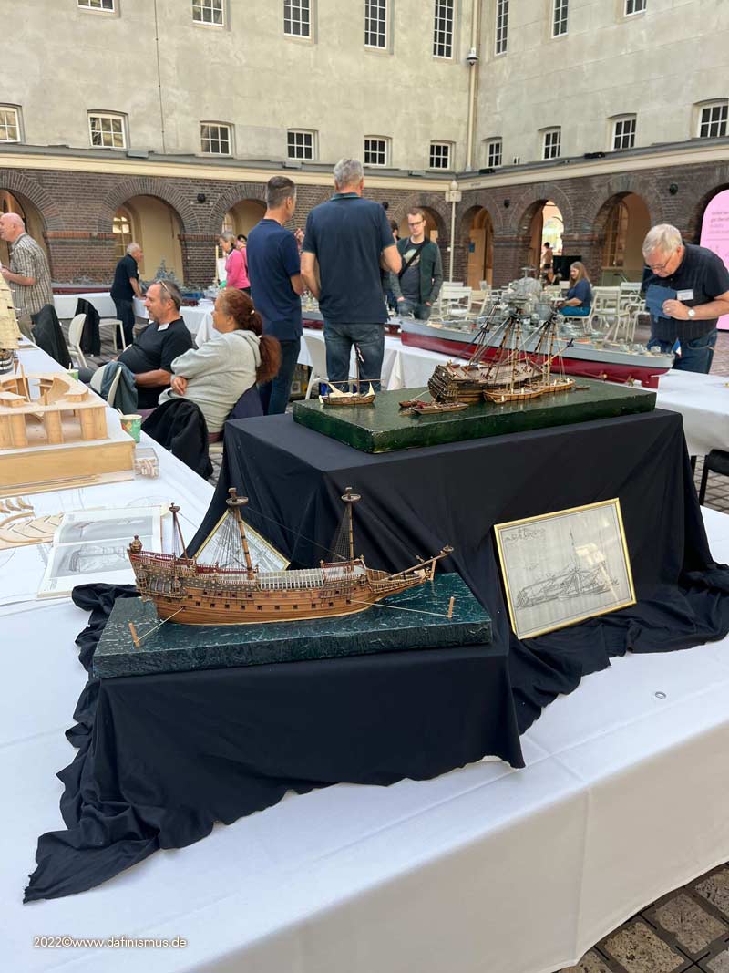
And my little round one was sitting in the mids all these other great models.
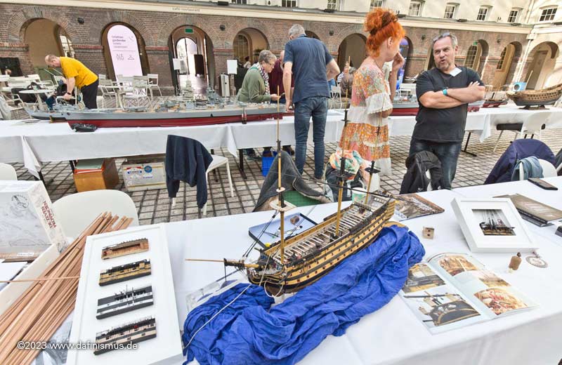
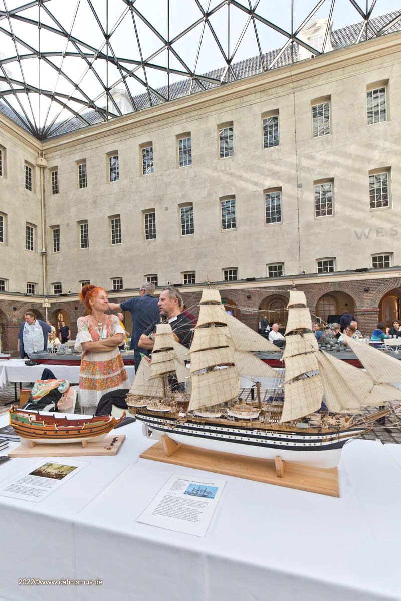
Right next to it the Joachim Schiffebastler with his big Amerigo and his small Berlin.
And here comes Schmidt 🙂
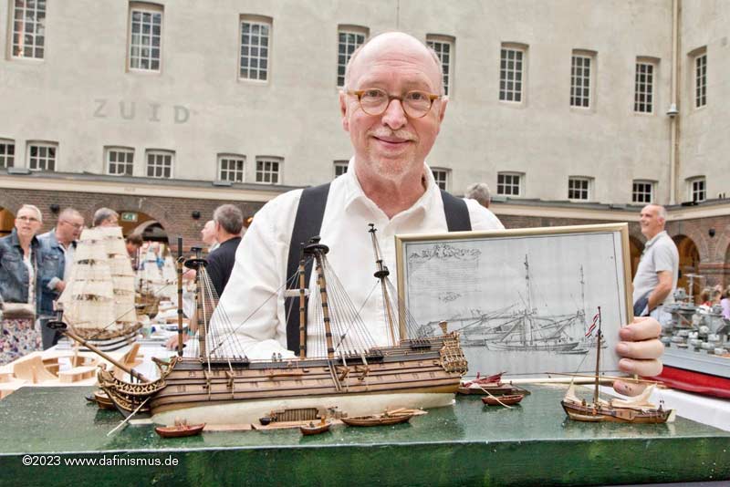
Great to see him grinning.
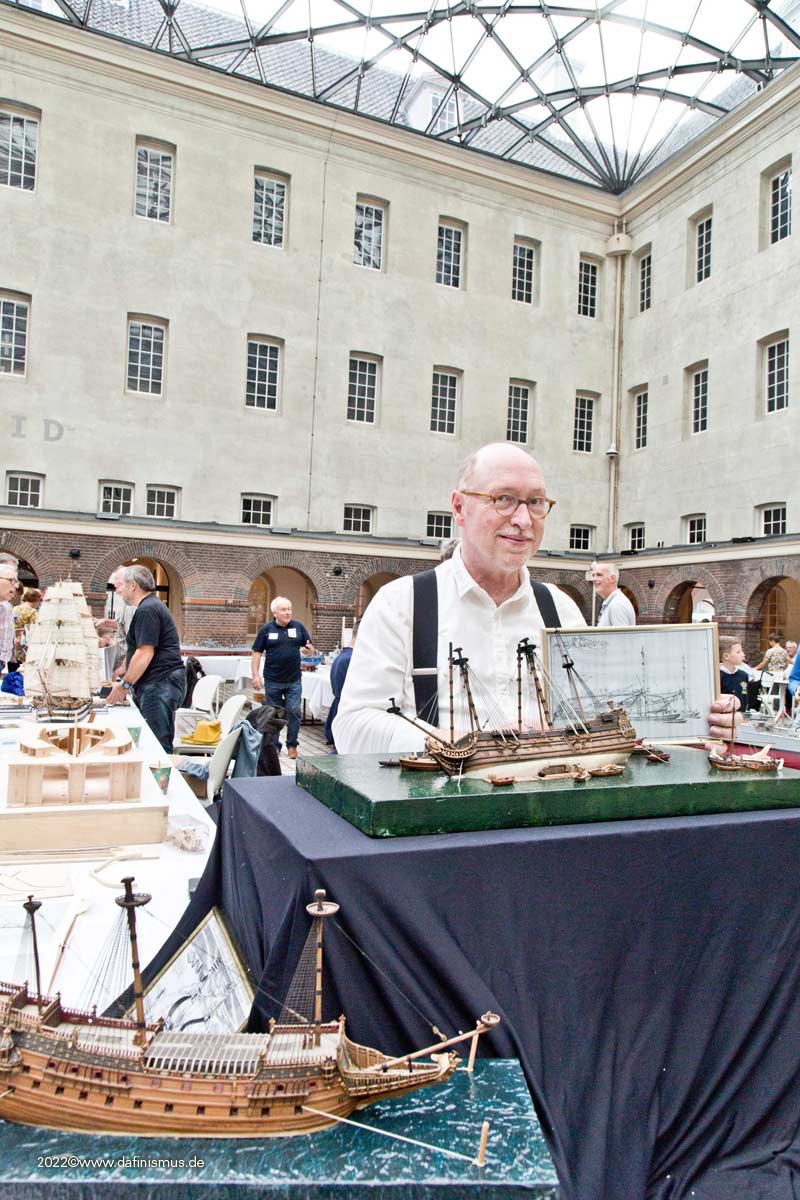
Simply a feast for the eyes his little jewels.
Here comes AnobiumPunctatum Christian ...
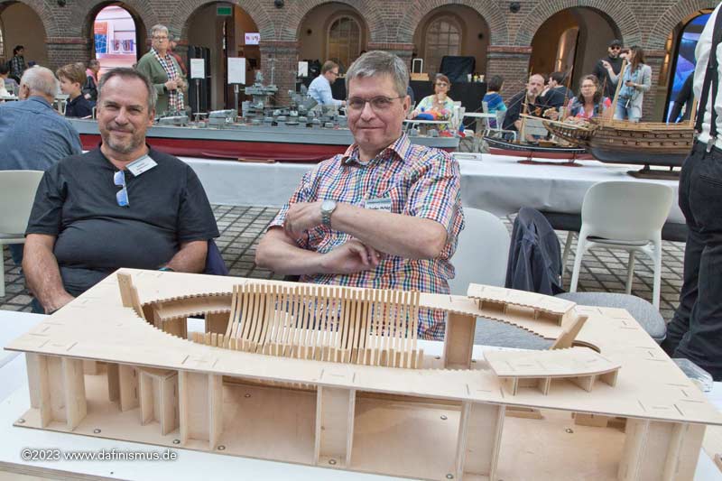
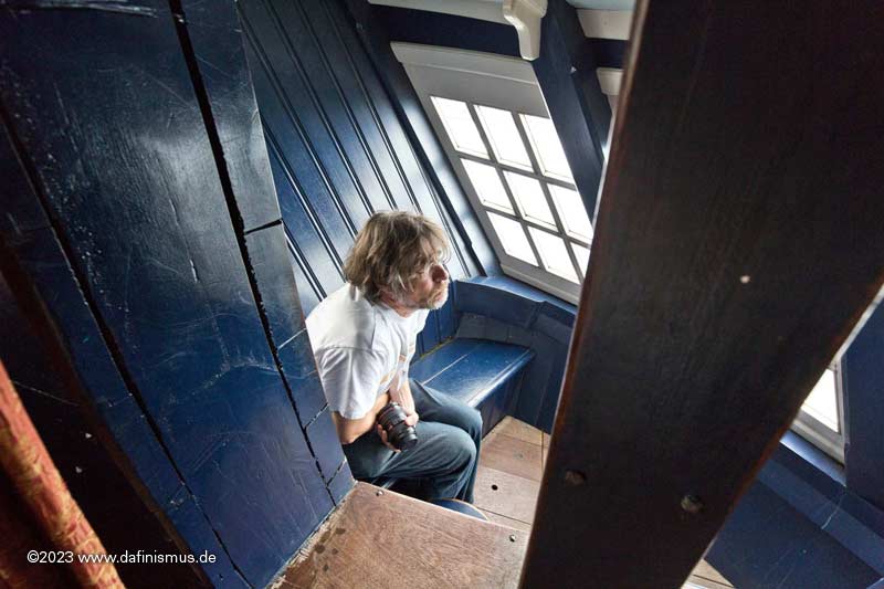
... and also a dutch amateur was also there 😉
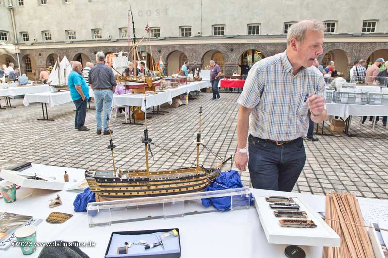
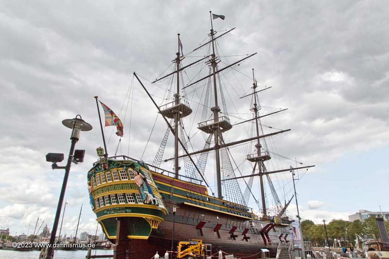
The museum itself was unfortunately very poorly stocked, but there were still some great things. For example this model ...
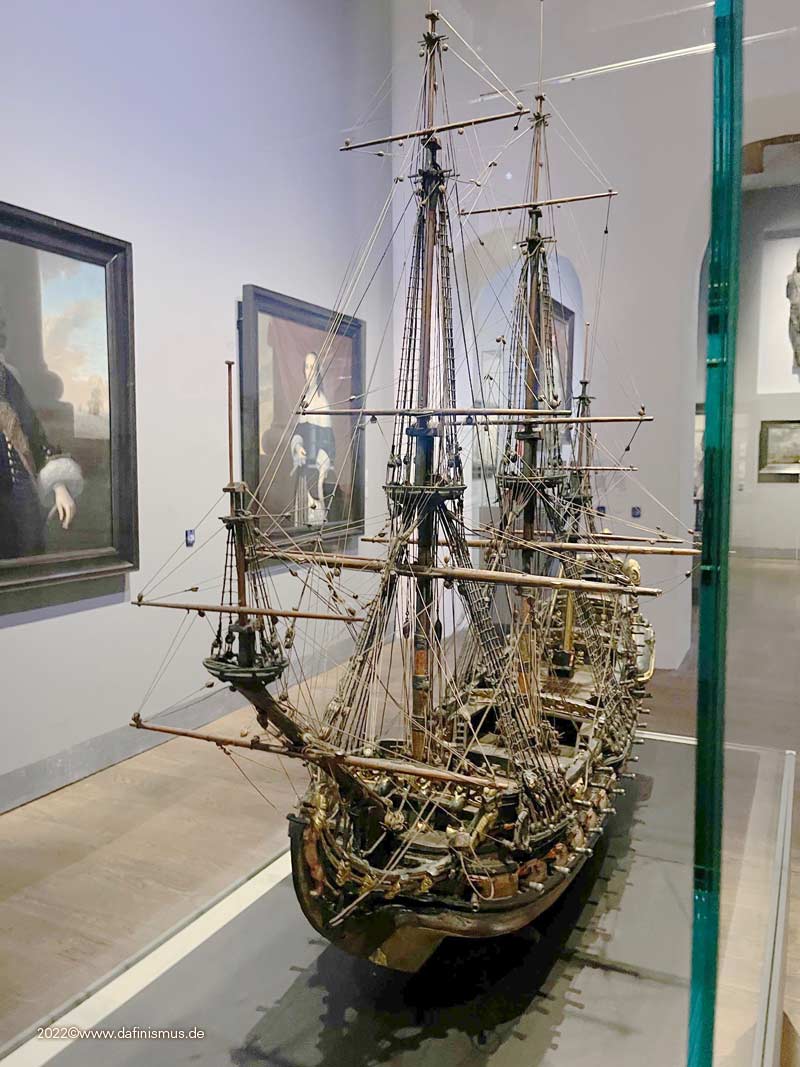
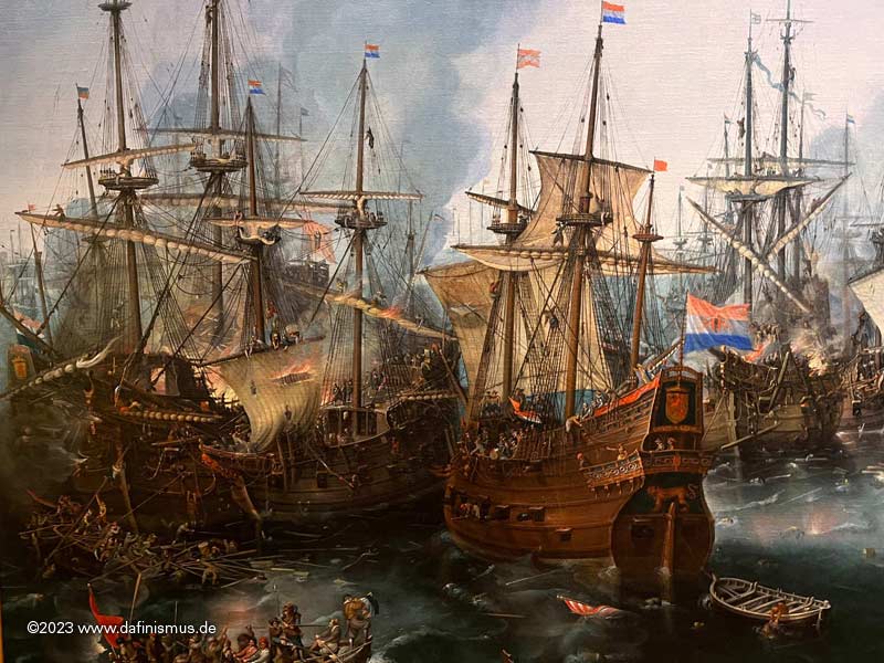
... and some battle paintings that are well known, including one of my favorite scenes with the gentleman sitting astride the gun wiping out the cannon, who can find him?
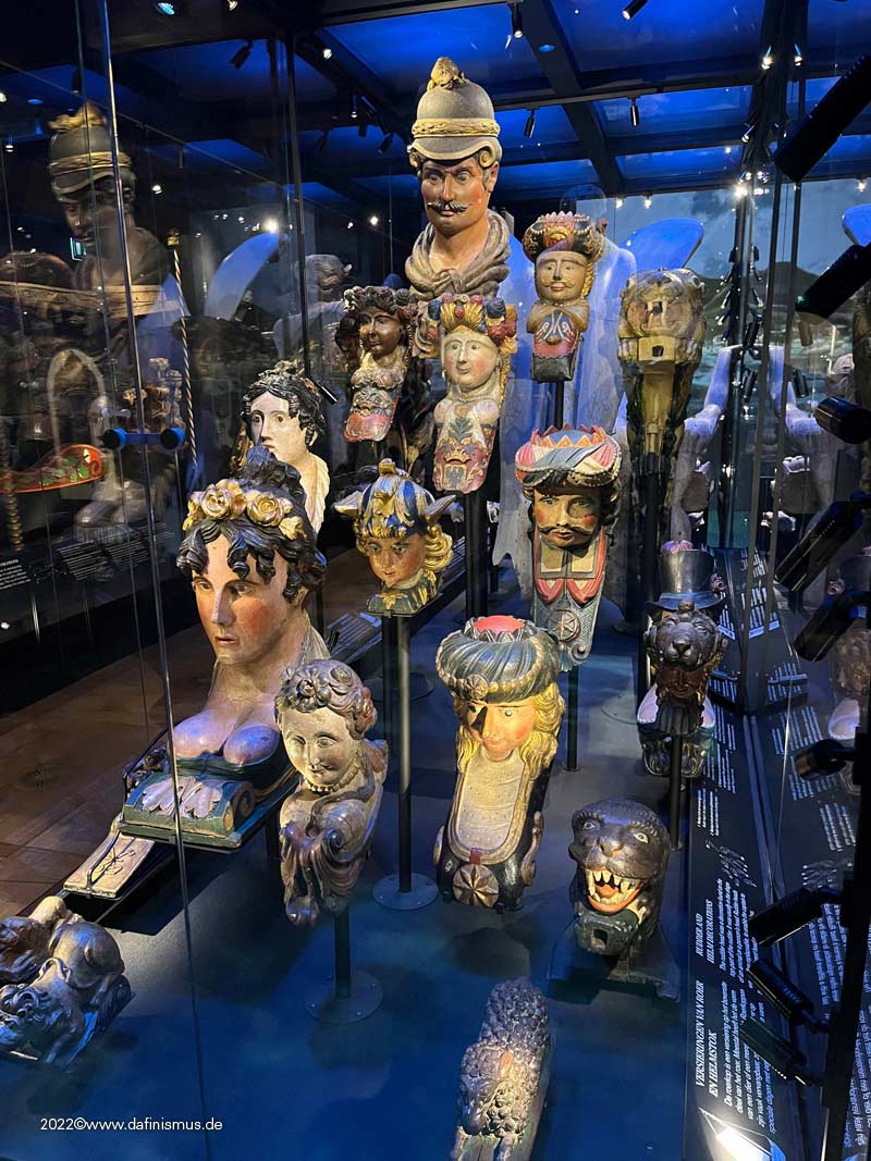
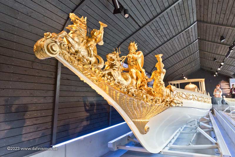
The collection of figureheads was fascinating ...
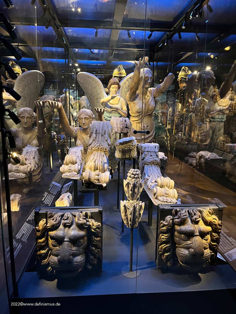
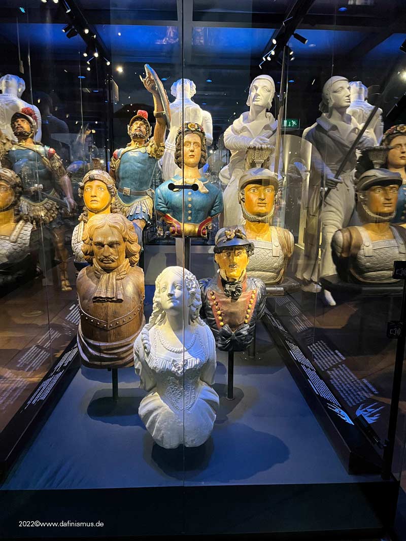
... so was the imperial bark.
Then came Disneyland ;-)
I spare you most of the pictures at this point, only once it was stronger than me http://www.shipmodels.info/mws_forum/images/smilies/icon_wink.gif
Then shortly after Oudeschild on Texel ...
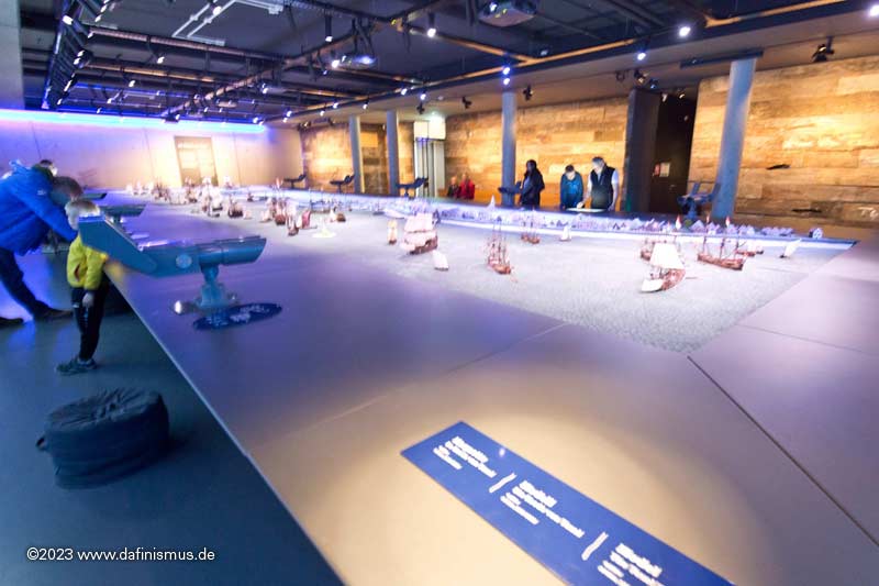
... and looked at the wonderful diorama of the Texel roadstead. Madness!
And then via Middelburg and Aachen back home.
It was nice, met a lot of great people, learned a lot, laughed a lot and had a great time 🙂
Greetings, Daniel -


Copper plate overlapping (< > 1794) - lower overlaps upper or vice versa?
in Building, Framing, Planking and plating a ships hull and deck
Posted · Edited by dafi
Hello Alan, yes I am completely with you, most of the times the riveting is out of scale at small scales.
At my Vic at 1:100 I refused for that reason for a long time to simulate the riveting until I found something in the shelf of the bathroom: a derma-roller of my then dear lady :-0
A torture instrument in my very eyes, I saw the other qualities, I disassembled one and gave a different distance for the spiky wheels and a new handle and then things kept rolling 😉
The result was quite like I feelt it should look like, very subtle to the naked eye, it gives a kind of structure that is feeling quite welcome on the whole of the coppering.
I also opted for the naked keel.
I know the basic flaw are the overscaled scales of the Heller kit, but over all it leaves a "good impression."
XXXDAn