xken
-
Posts
841 -
Joined
-
Last visited
Content Type
Profiles
Forums
Gallery
Events
Everything posted by xken
-

Recommendations For A Good Milling Machine
xken replied to Thistle17's topic in Modeling tools and Workshop Equipment
I agree with all the Sherline remarks, I have the lathe and the mill set up using my lathe motor and would recommend them to anyone. One word of caution on all the Chinese built machines whether lathe or mill is that the bearings wear fast. My lathe went in three years with medium usage on brass and aluminum only. They come with ball bearings from the factory and can be replaced with a taper bearing set from The little Machine Shop. They also do not have the accuracy of the Sherline on small close tolerance work. Think of the size that you will need to be working on since both have scale limits. -
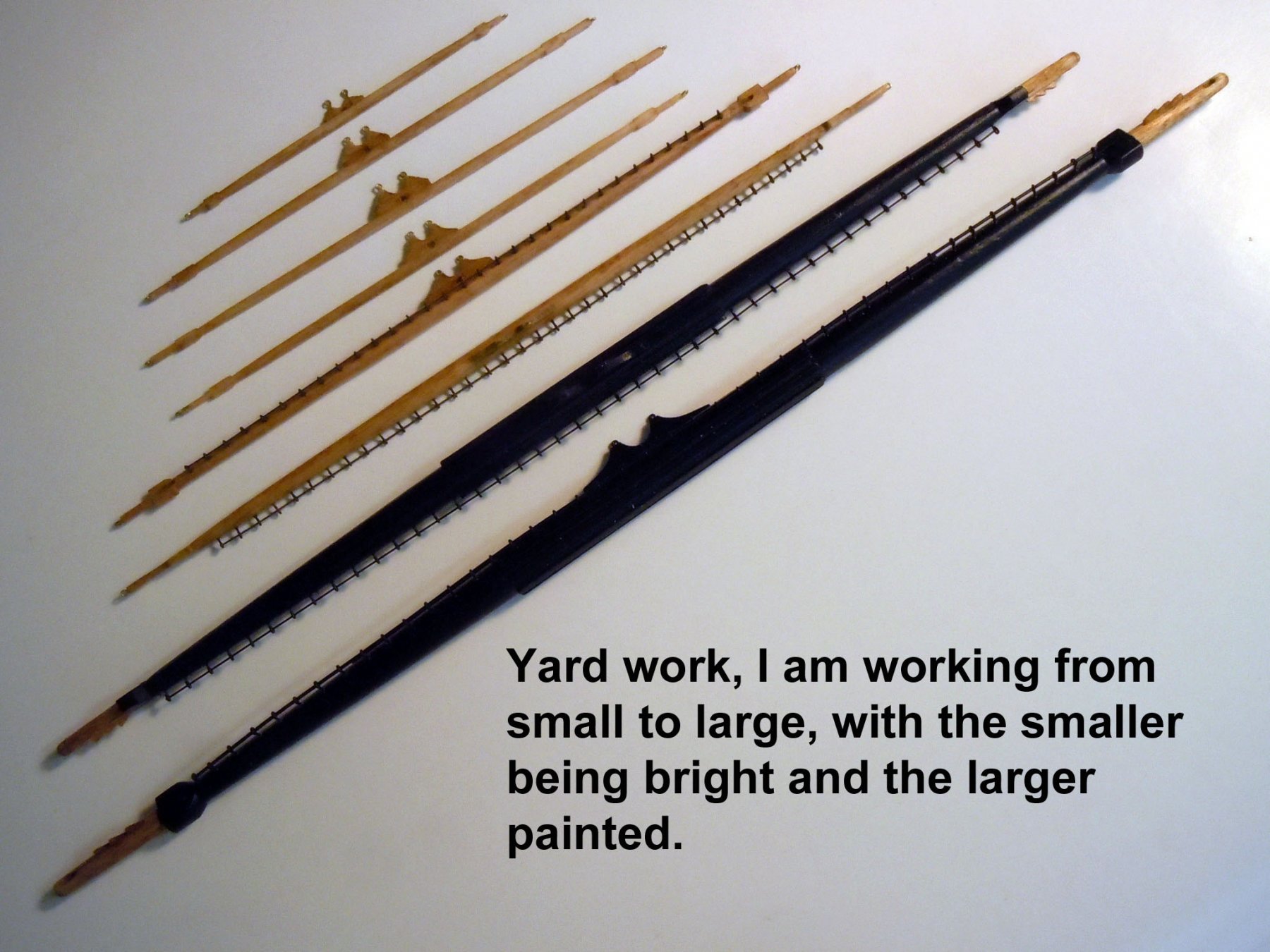
Jon, working from top down is just my personal way of keeping the larger yards out of the way while rigging the upper yards and easier to route the longer lines down with less interference. As you work down it is easier to route the shorter lines. With the lower longer yards in place they get in the way as you work up with greater risk of breaking them. The pins were originally intended to be temporary but I decided since I will be transporting it across the country to Long Island where my son lives it might be safer to just glue them in place. Also with twin boys better to be safe than sorry.
-
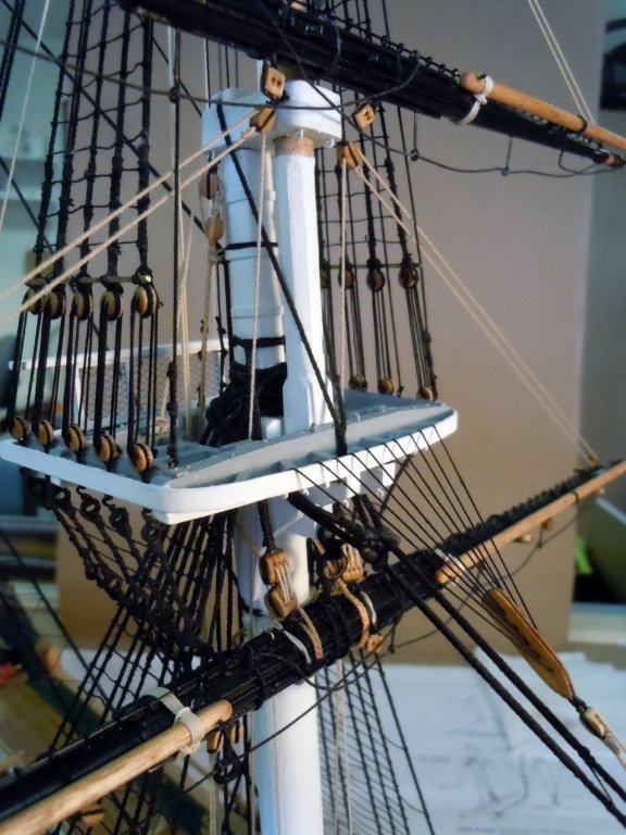
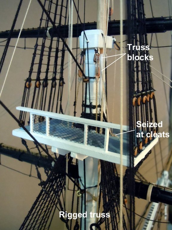
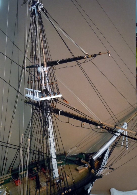
Rich you can do it, just take your time and think through it and remember that "God is in the details!" After a few days off hosting an out of town guest I am back at the fore mast rigging. I had to resolve conflicts between pictures of the real ship, the plans and AOTS book on various rigging details. I went with my best guess. One thing I learned was to work from the top down adding the yards and pinning them with 1/32" rod which really helped in rigging. The upper yards were easy but the course yard was a real challenge especially rigging the truss once the yard was in place. I also was making the ropes needed and sanding the kit blocks as needed. The other challenge was routing the lines without interfering with others already in place and look real straight. I also used the plan map for the belaying pin locations versus other sources. Here are some pictures of the fore mast so far, once all masts are rigged to this point then I will add the brace lines. Here is a close up showing the cleaned up kit blocks. Here is a view of the biggest challenge rigging the truss with the yard in place. Starting to get a mess of ropes. Now on to the main mast now that I know what to watch out for. I am also glad that most of the deck furniture is removable which really helped in tying off the belaying pins.

-
casting metal parts including cannon
xken replied to rtropp's topic in Metal Work, Soldering and Metal Fittings
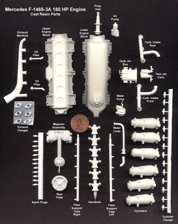
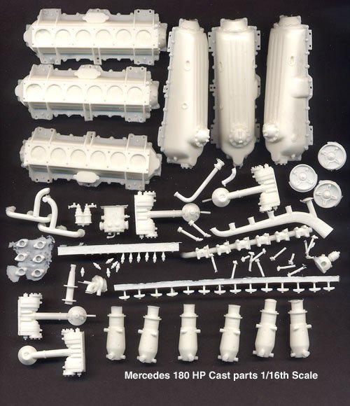
If you wish to cast anything visit and explore this site. I have used their product 320 resin for pressure casting 1/16 engine parts. As with anything you need the correct materials and tools and most of all a good master. RTV silicone can pick up a fingerprint in a mold. Also printed master parts will have the stepped texture that will require finishing versus metal masters that will have a smooth finish. https://www.smooth-on.com/tutorials/ The parts below were pressure pot cast with the 320 resin hand poured into silicone molds. The US penny will give you a sense of scale.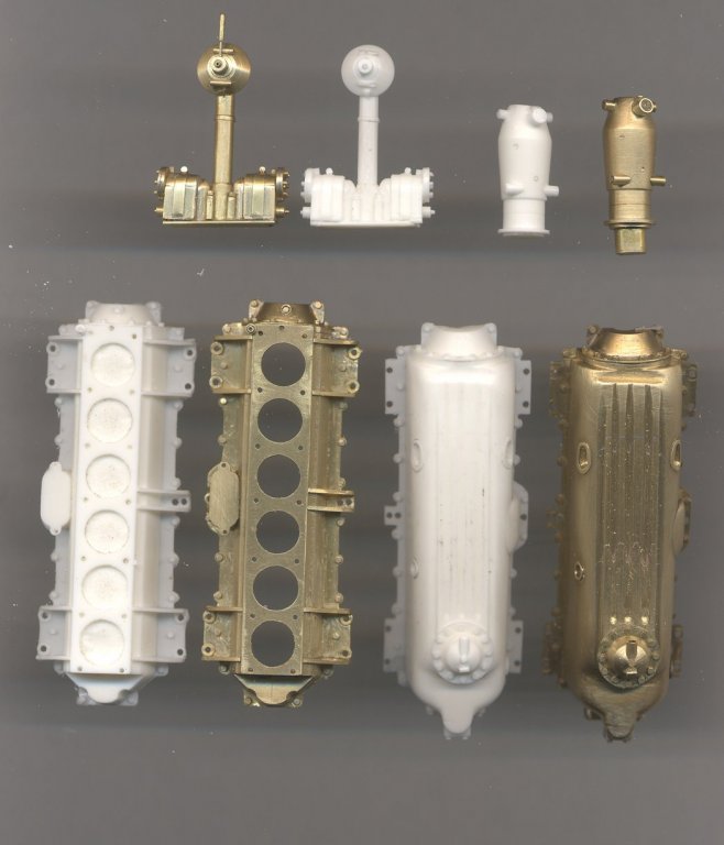
-
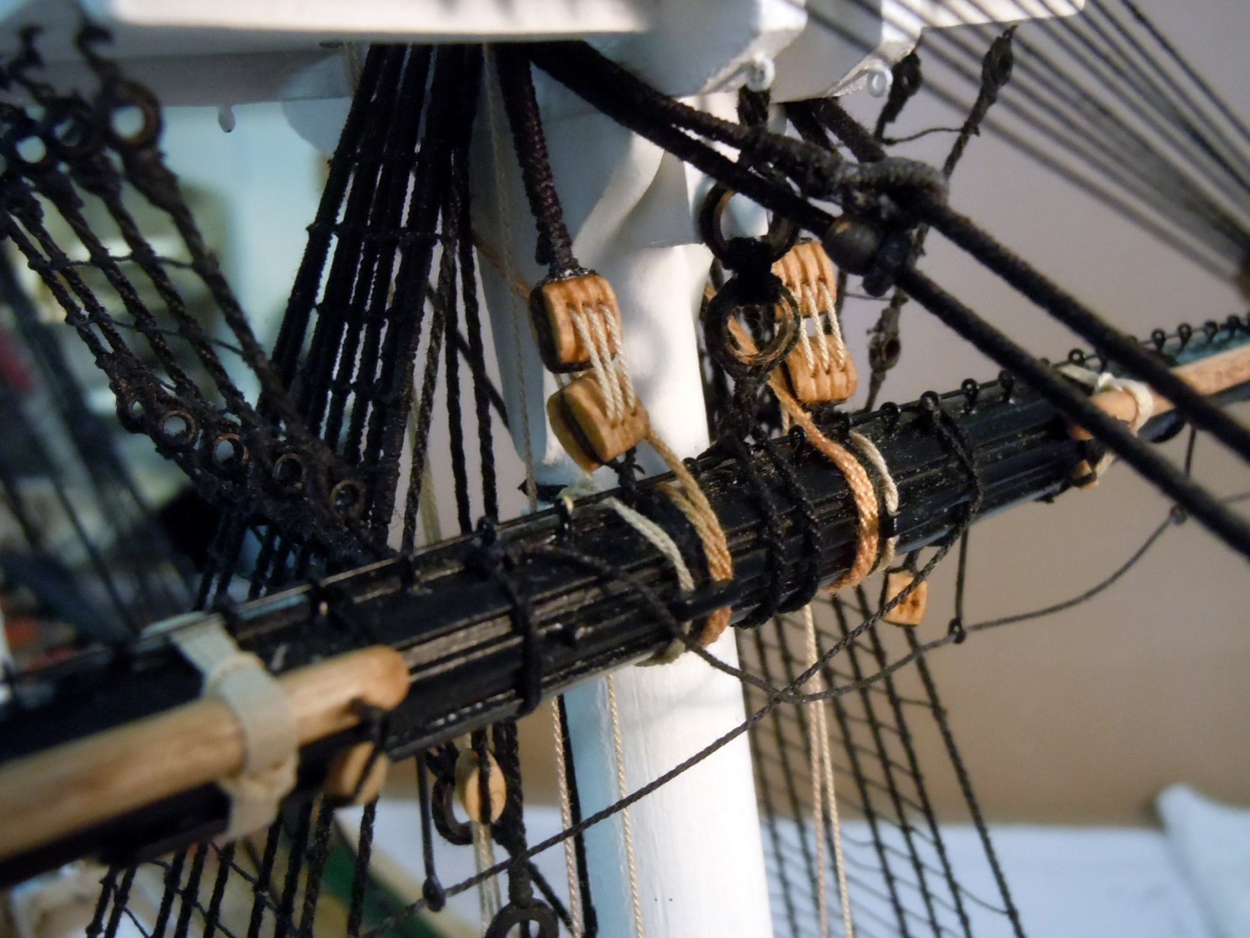
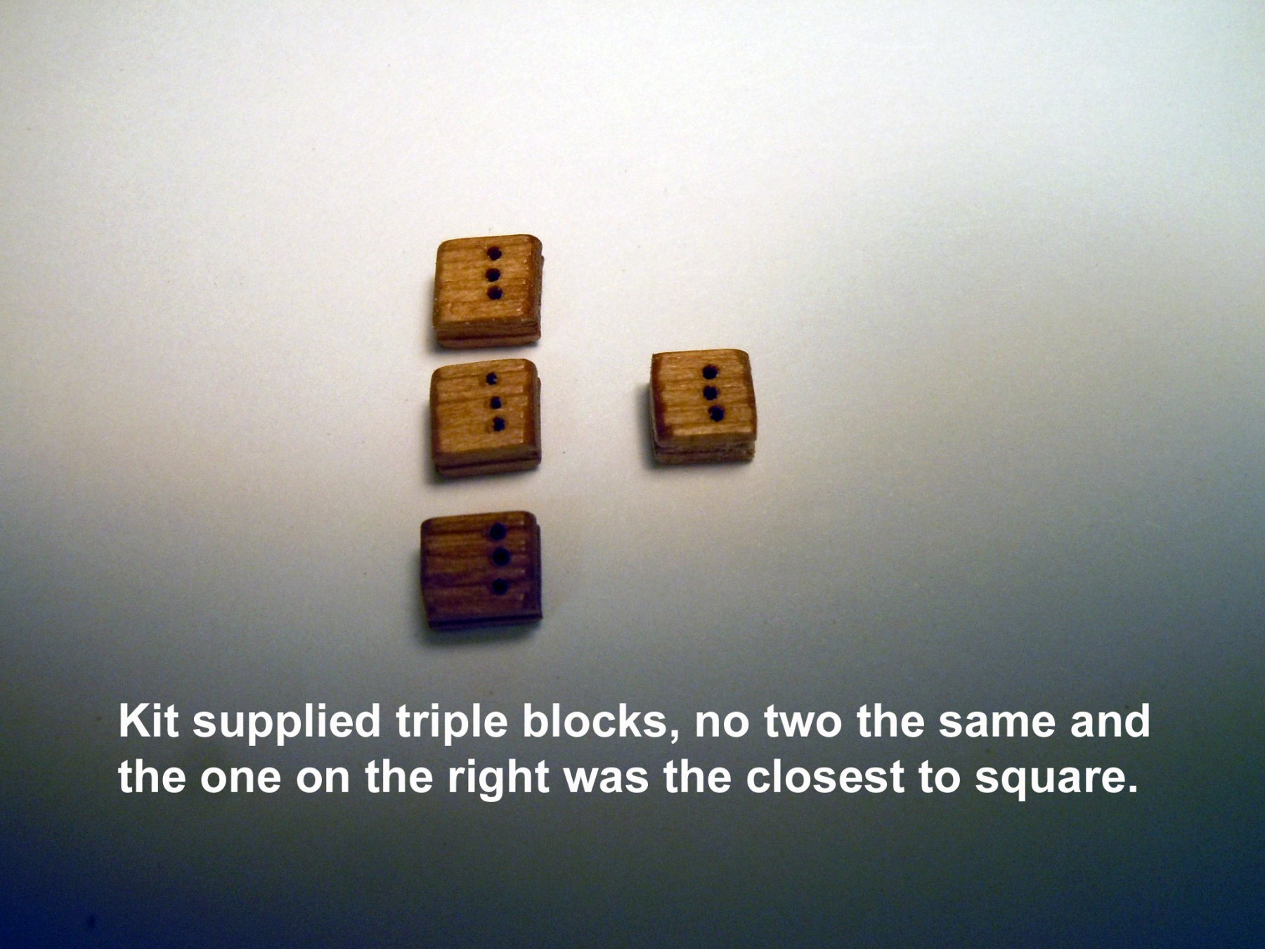
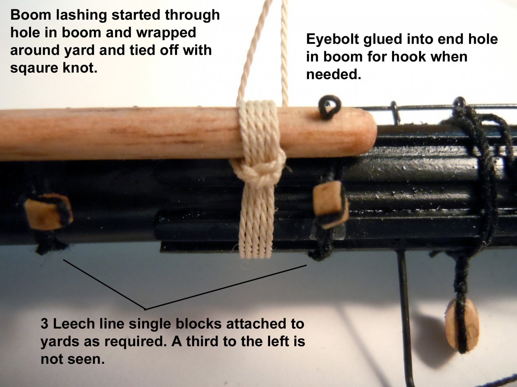
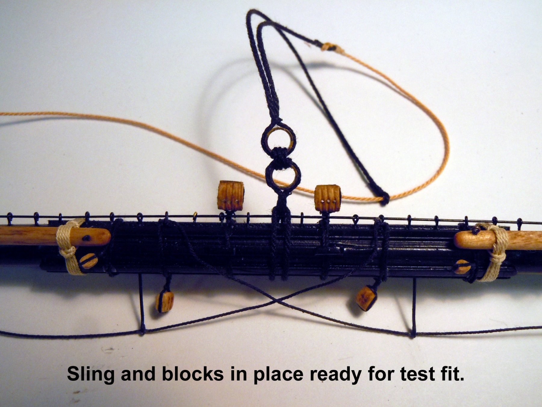
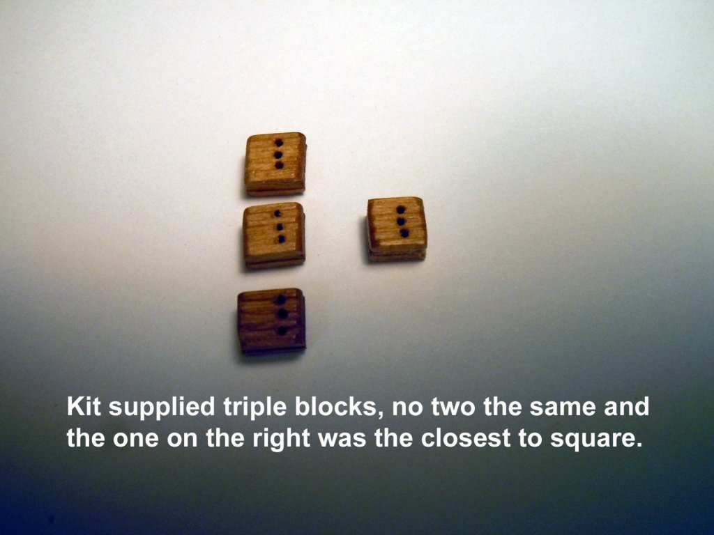
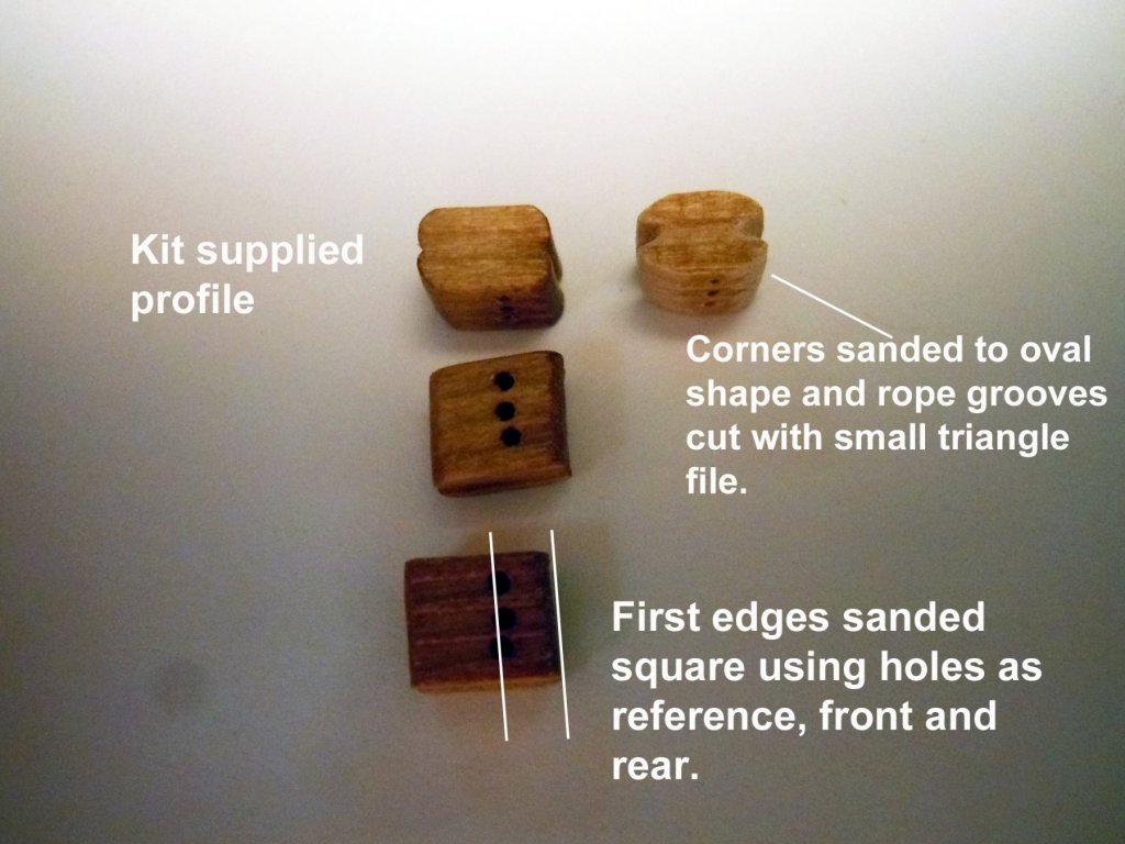
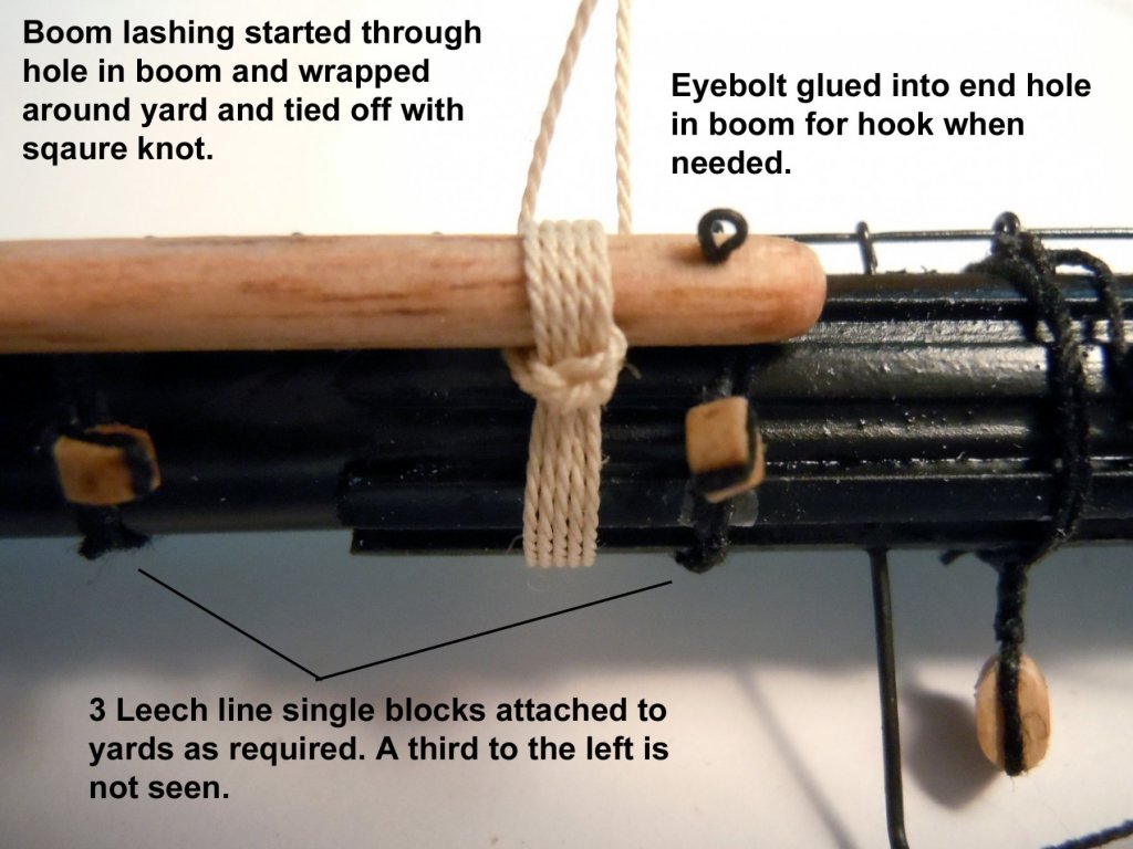
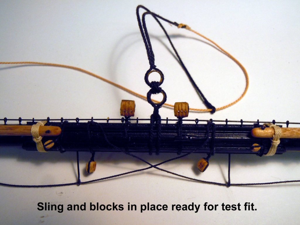
Decided that I needed to build out one yard to learn was was needed after doing some detective work between the instructions, plans and other sources and did my best guess. But first the kit supplied blocks, all sizes needed help. All needed to be sanded from square to an oval shape. The singles were easy but the triples really needed a great deal of fixing. Next thanks to Johnathan I sorted out the stud sail booms with the lash line inserted in the inner hole since it had to stay in place for both stored and rigged positions and the end hole getting an eyebolt for the hook to set or retract the boom as needed. The lashing was tied off with a square knot and ends tucked under the boom and cut off. I then added the sling after turning thimble rings from brass and darkened. I also added the triple blocks as well. It took a couple of fittings to get the length of the rope correct fitting over the cap as well as the lashing rope tied to the end loop. Here is a test fit of the foremast yard in place. Now I can finish up rigging the jeers temporarily. I am using 1/32" removable pins to locate the yard in position on the mast. Hopefully by now I know what is needed on the rest of the yards.

-
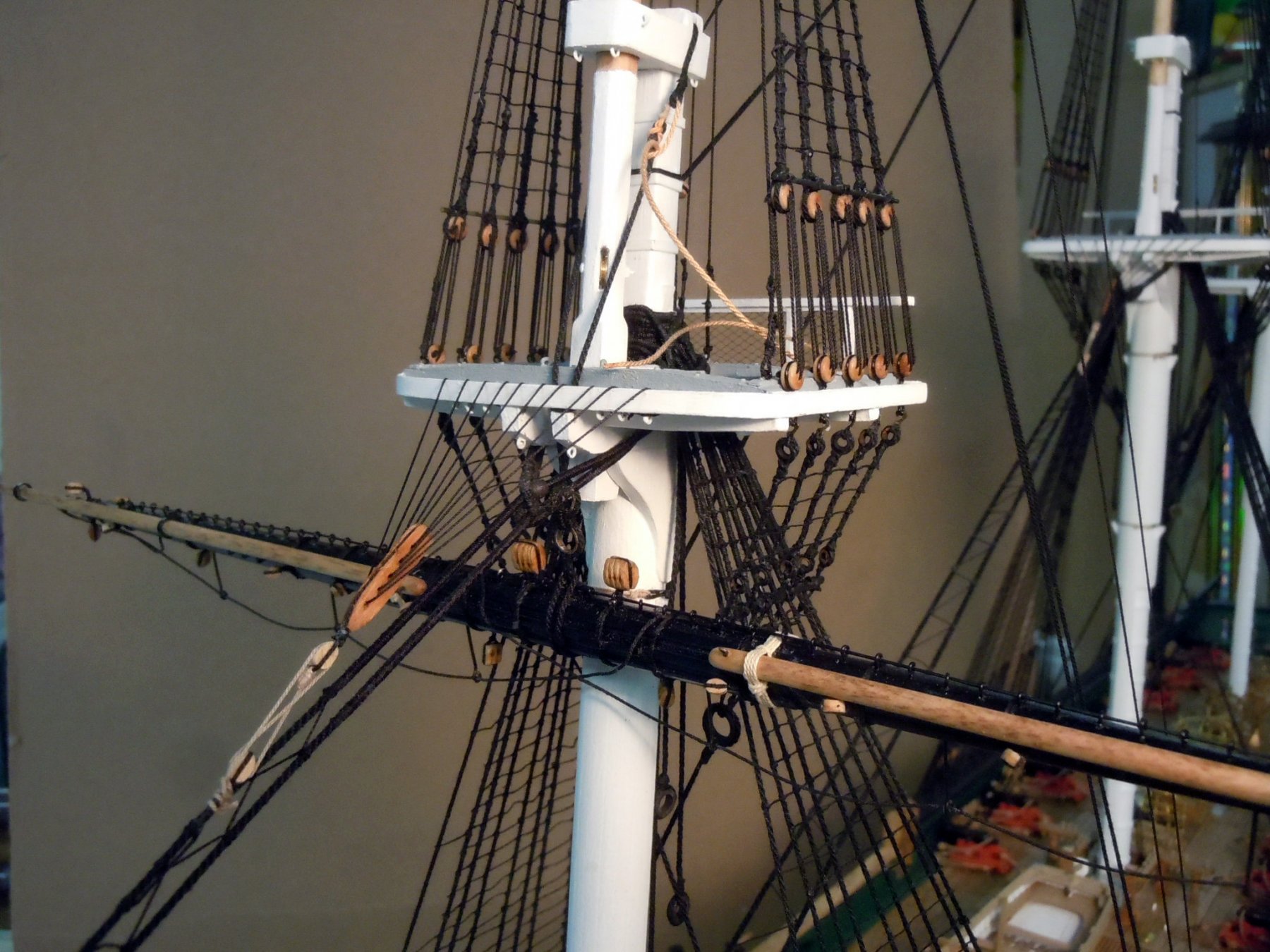
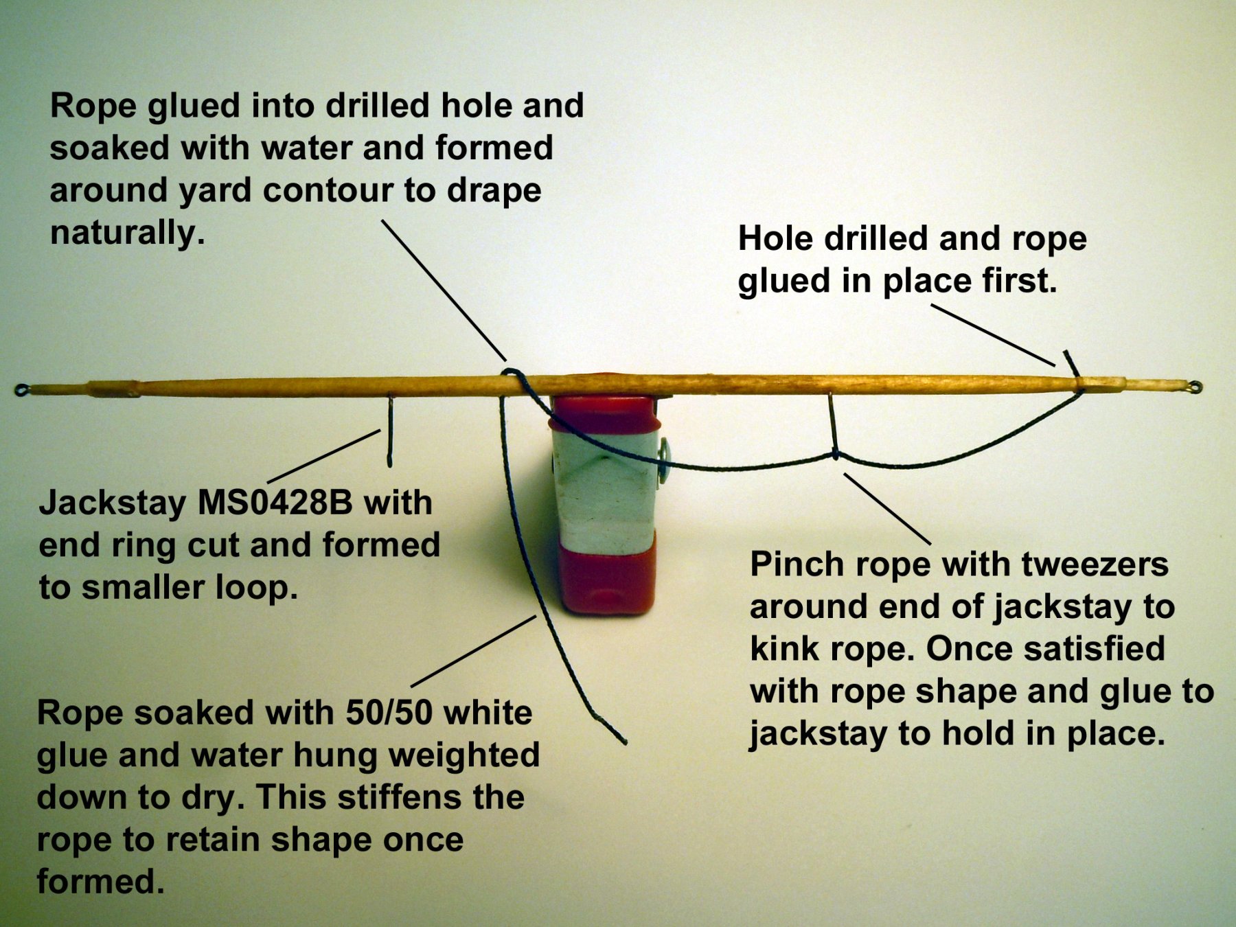
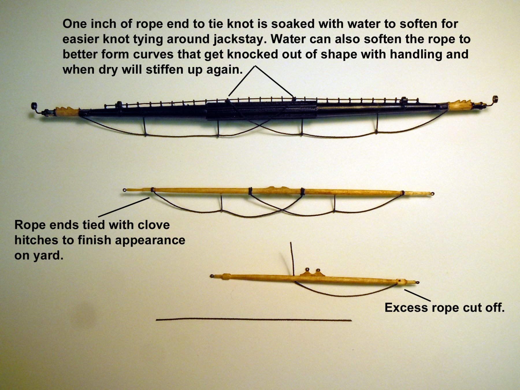
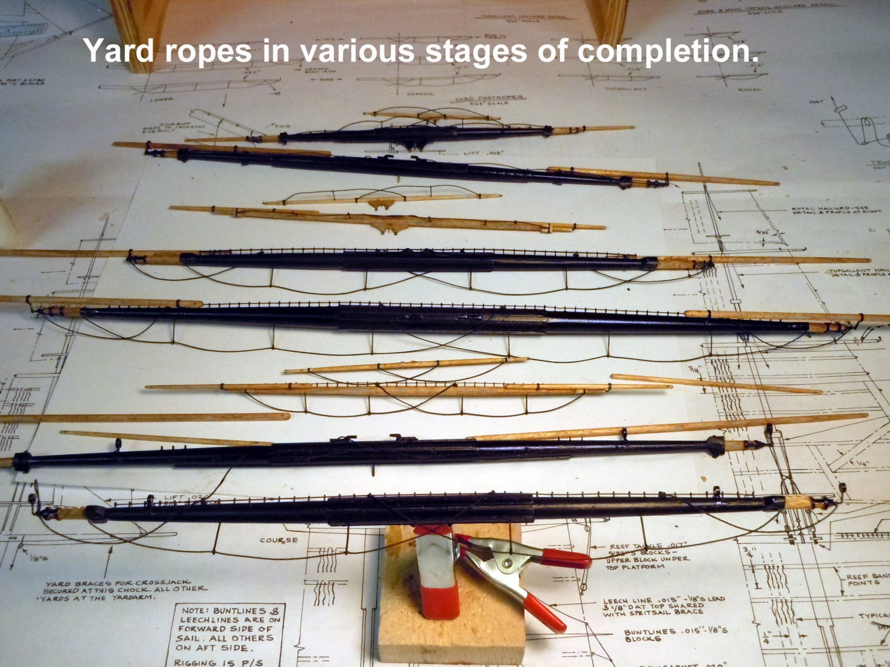
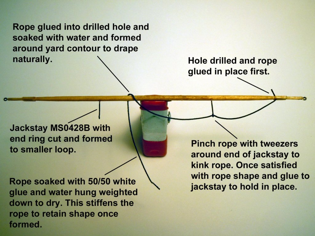
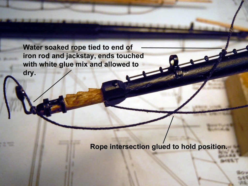
I finished up all the booms and drilled the ends per the drawings. I moved on to the foot ropes on the yards and decided to use brass jackstays indexed into the yards for a better finished look when completed and they are easier to set the foot ropes with in the end. However, I did have to cut the end loops of the MS0428 to make them smaller. After making the ropes I soaked them with 50/50 white glue and water and hung them weighted down to dry and set straight and stiffer than normal rope. This helps with the forming of the curves see in the real ropes. Also when a knot needs to be tied I soaked one inch of the end to soften the rope for tying off. Water can also soften the formed rope for final shaping and will stiffen up again once dry. Here are some pictures of the results and I know that with handling some abuse may happen, but can be fixed with wetting again. Next I will be adding slings blocks to various yard locations.

-
Johnathan, you hit a home run on that one. I now understand why the two holes, one is for the lashing at the heel in both the stowed and extended positions and the second hole is for the loop to hook into when pulling the boom out and then moving the hook to the end to retract. It also looks like the rope goes through an eyebolt on the backside of the yard which may be how the hook is stored when not in use when the boom is lashed in place. This is a detail that I have not seen on other builds.
-
Johnathan, thanks this is exactly what I was looking for. Fig 347 says it all. Thanks again for getting this information!
-
Jonathan, how is the end of this boom (in the rings) pulled in and out? The plans show two holes drilled 90 degrees to each other on the left end. Must be some kind of ropes to pull in and out. This is the details I am after.
-
Johnathan, great read and glad you accepted the challenge; however, this focuses on the stun sails themselves and how they are rigged. The swinging boom is mentioned and I have those installed, what I do not have is how the "stun sail booms" are hauled in and out on the yards. These are the booms that are in the rings and the plans only show them lashed in the stowed position. I am trying to find out how they, the booms were rigged to pull in and out through the iron work rings. I will try doing a picture later. Thanks again for your help!
-
Johnathan, thanks for your efforts but I also found these on the net. What I really want to know is not about the sails, but the booms and how the booms are pulled in and out within the rings on the yards. If you look at each sail, the top edge is attached to a small yard that is suspended from the middle of the boom in pdf 2. I want to know how that boom is pulled out into the position shown in the pdf. What ropes and blocking are used to get them into position. Again thanks for your efforts!
-
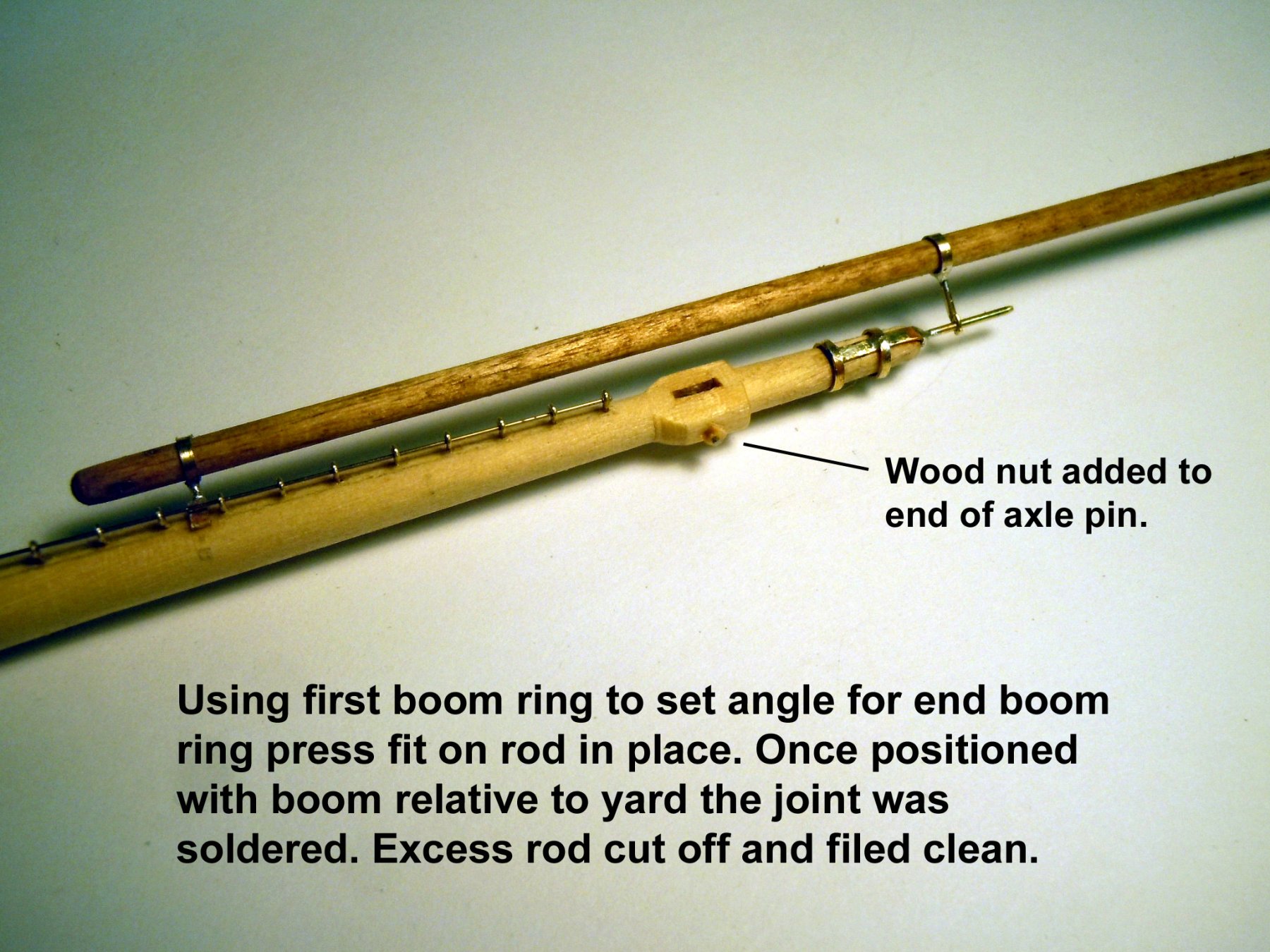
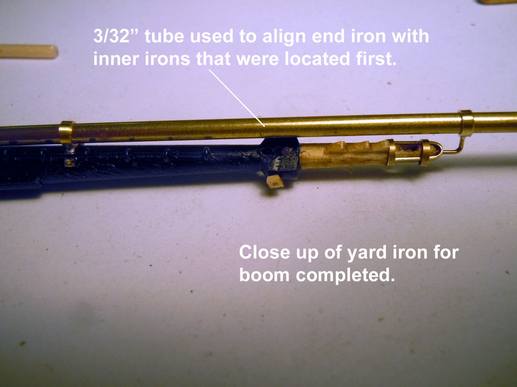
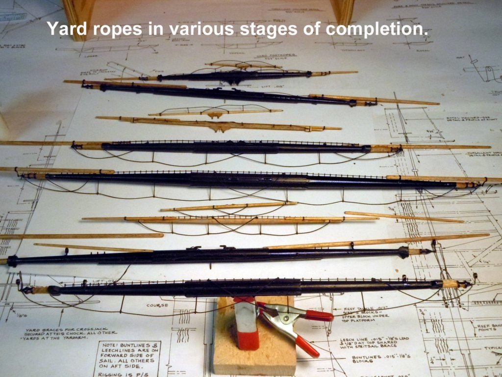
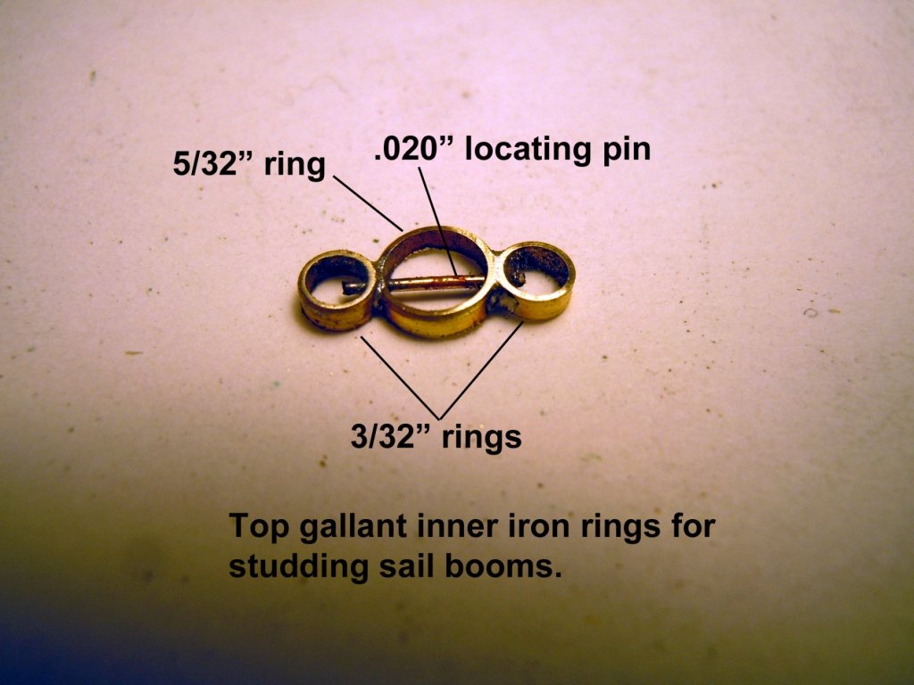
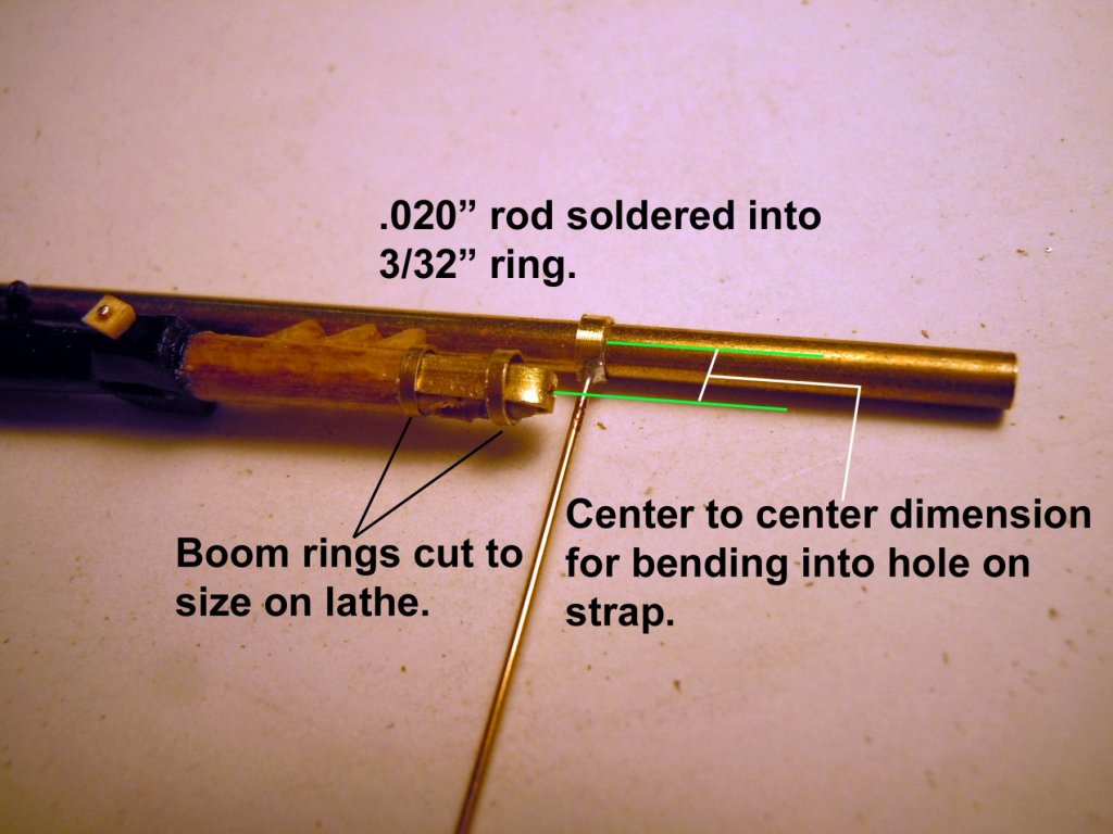
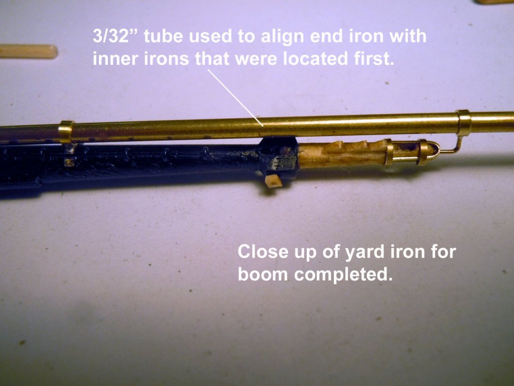
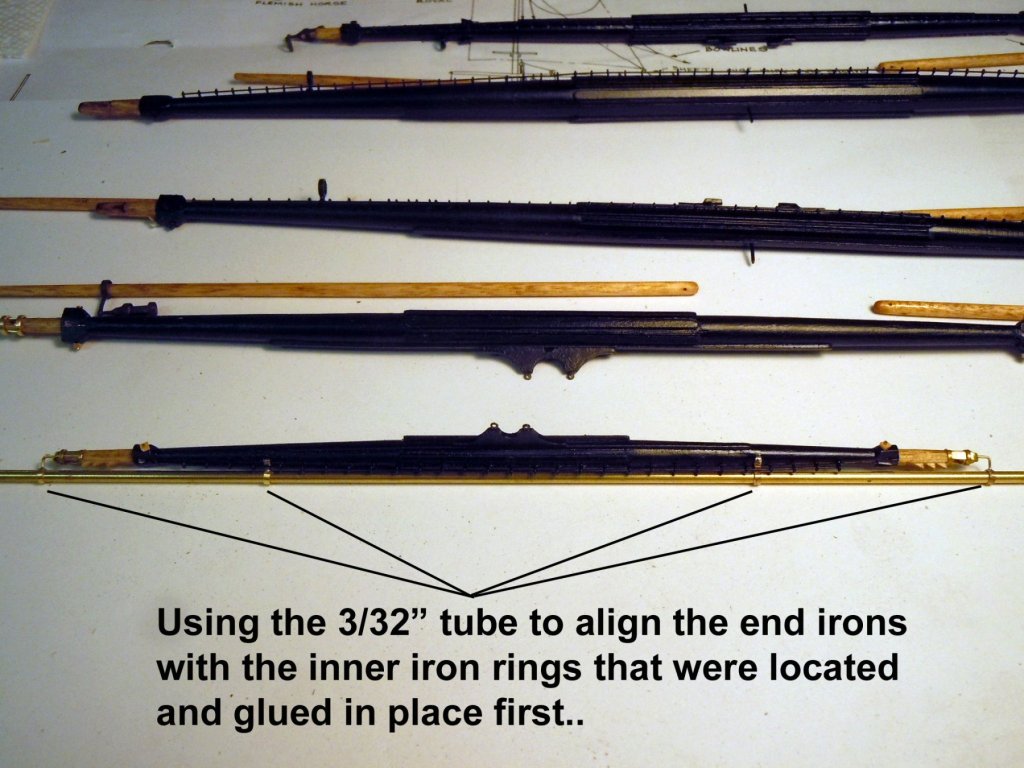
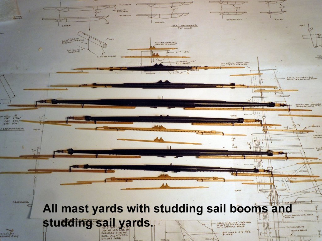
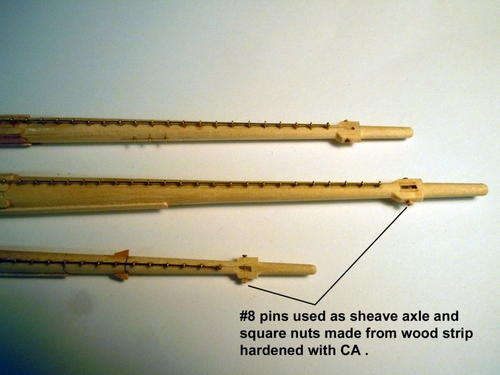
Jonathan, it is easy just requires patience and the right tools. For example I cannot imagine building this ship without my lathe and mill setup. Michael thanks and second Michael, if I had known grand kids were so much fun I would have had them first. I have completed the basic fabrication of all the yards and booms identified on the plans with respective ironwork. When I got to the smaller yards I had to change to 3/32" rings soldered with .020" rod for the correct scale. The inner rings were soldered together with no post necessary due to size and end rings rod was just bent to fit the hole in the end strap. I also used 3/32" tube to align the rings to the yards end to end as shown below. Here is a family portrait of the yards, studding sail booms and studding sail yards. Now I will start rigging the yards do do as much as possible prior to mounting to the masts. I am also going to add a removable 1/32" locating pin to the center of the yard to index into the mast to aid in rigging. I understand that the studding sail yards were attached to their respective sail and rigged to a block at the end of the studding sail boom. Now for the magic question that I have searched for to no avail..."How are the studding sail booms rigged? I have no reference on the plans, or the Anatomy book on how these were rigged even though the plans show two holes drilled at 90 degrees in the inboard ends. Does anyone know how these were rigged or lashed or moved trough the rings on the yards, I cannot imagine that these were moved by hand? I am hoping someone with more rigging knowledge or reference sources than I can help.
-
Mick, great build and yes don't you just hate when work interferes with shop time. I love the brass work on the stove and it usually only takes one burnt finger to learn about hot parts; that is of course unless your learning curve is a circle. Keep up the great work! Ken
- 504 replies
-
- 3
-

-
- washington
- galley
- (and 1 more)
-
Tools You Can't Live Without
xken replied to Justin P.'s topic in Modeling tools and Workshop Equipment
Brain, eyes and hands all working together! -
You can wipe both the wood and the rubber clamping faces with acetone. The wood can be lightly sanded as well.
-
Others have identified the possible issue being the rubber jaw inserts. A couple of points to consider next time remove the rubber inserts since you are clamping and a portion of your clamping force is lost in the rubber; and use scrap wood of the same kind being clamped between the jaws and wood being clamped. Jaws or a harder wood could leave impressions in the wood as well. I suspect what you are seeing is mold release(silicone based) that is used in the production process. Try cleaning with acetone and then light sanding after the acetone has dried completely. This is just one of the many "Joys" of model making.
-
Sopwith F.1 Camel by jablackwell - Model Airways - WOOD
xken replied to jablackwell's topic in Non-ship/categorised builds
John, Love to see WWI planes being built; these are my first love in model building. Not sure how detailed you will wish to get, but here is a link to my scratch built Camel that was a commission for Fine Art Models at 1/15th scale per their request that you my enjoy for details. It also includes the bomb rack that was used on some. Looks like you are off to a great start and keep up the great work! http://www.wwi-models.org/Images/Foran/Camel/index.html- 114 replies
-
- 10
-
-
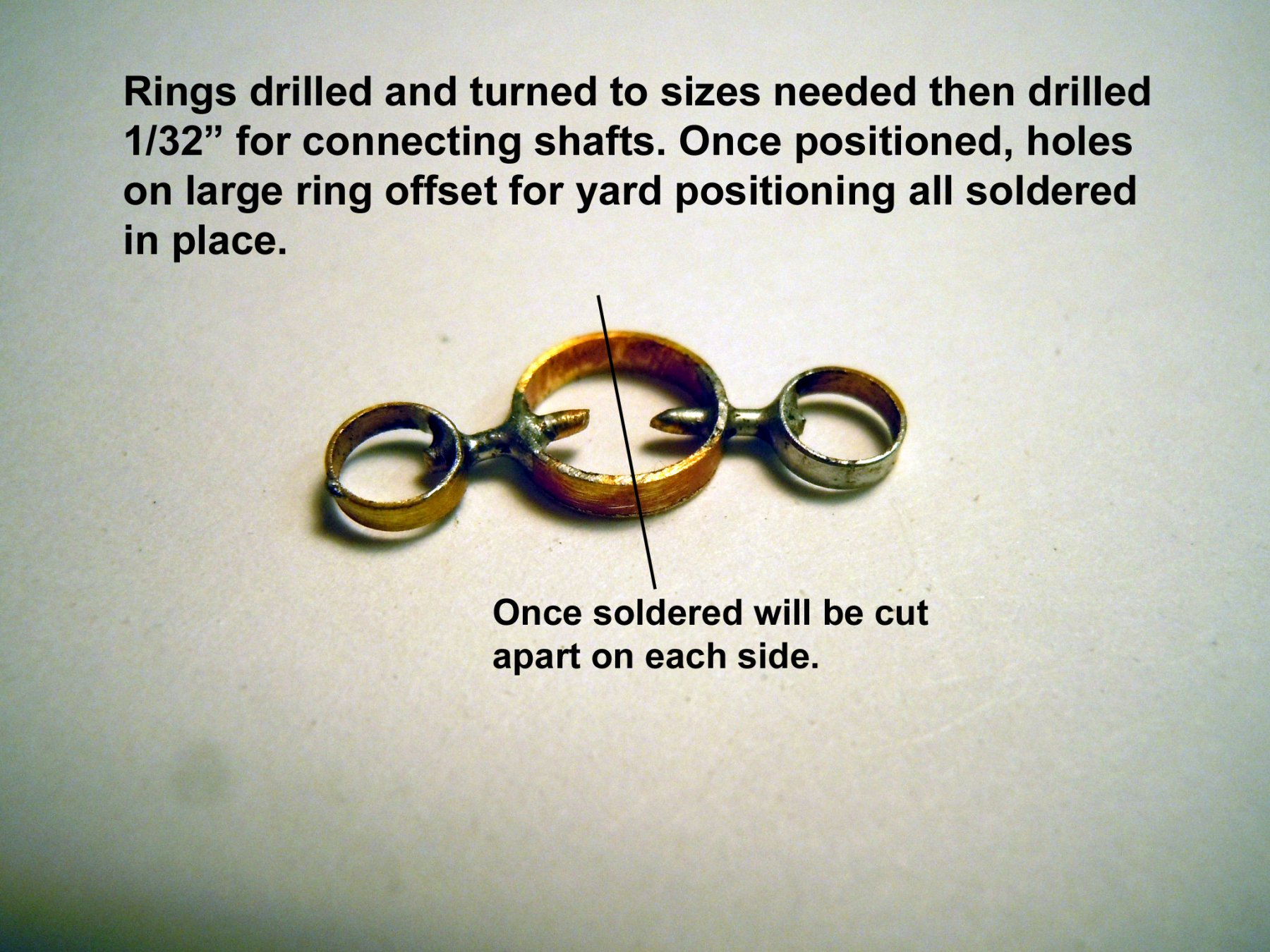
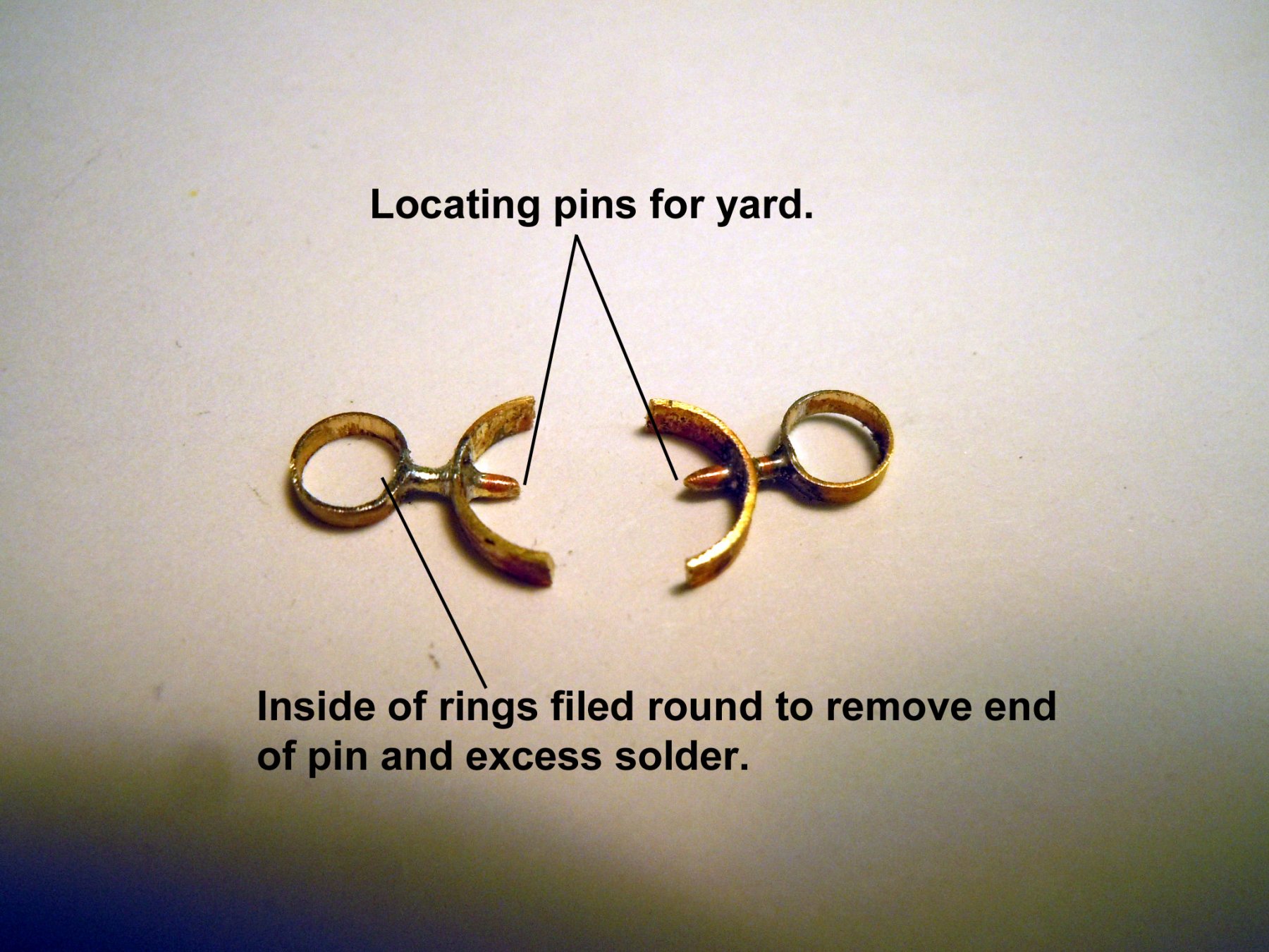
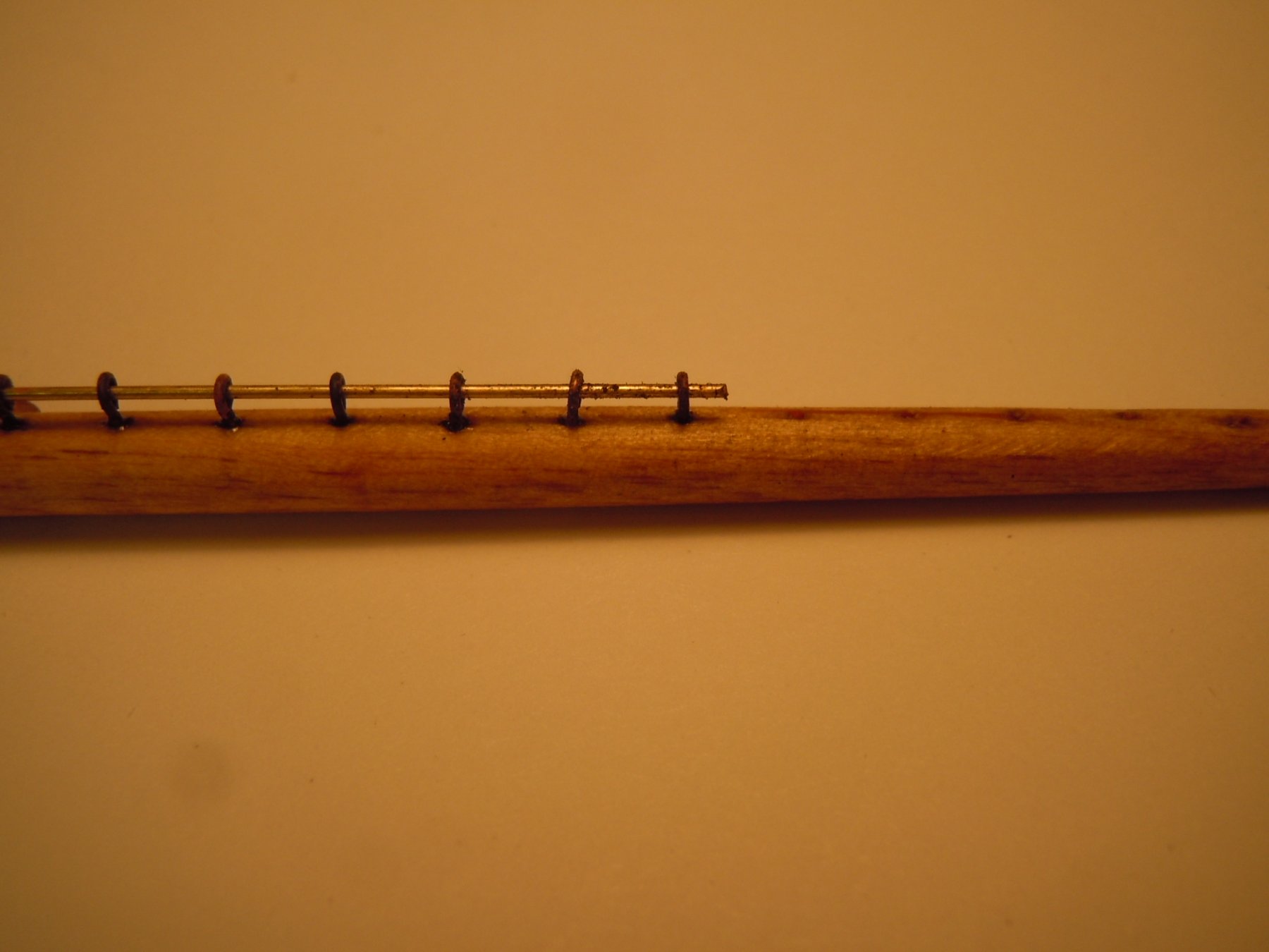
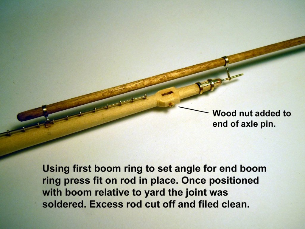
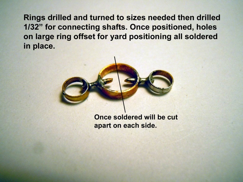
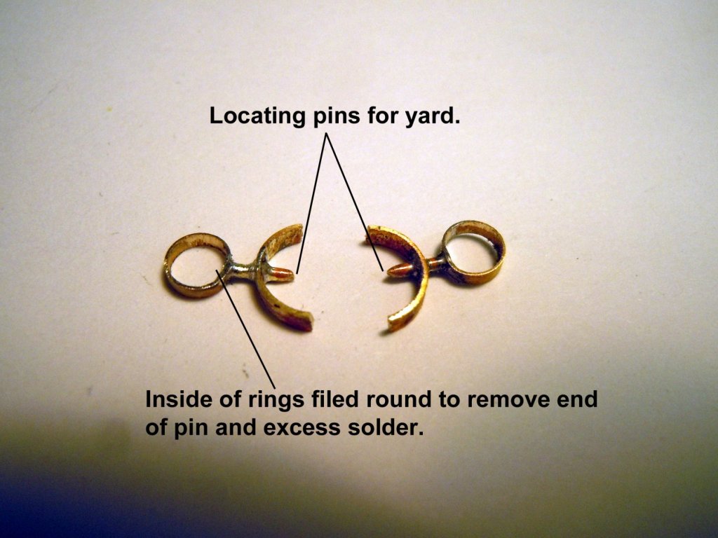
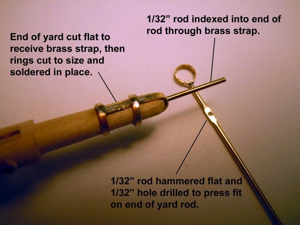
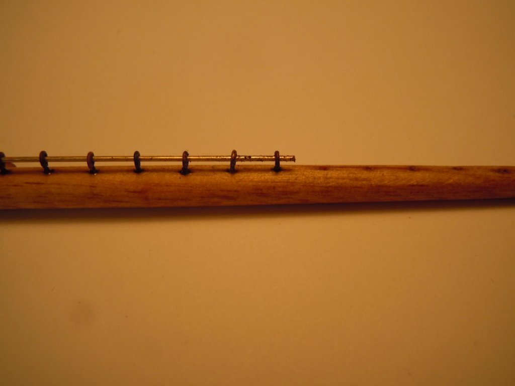
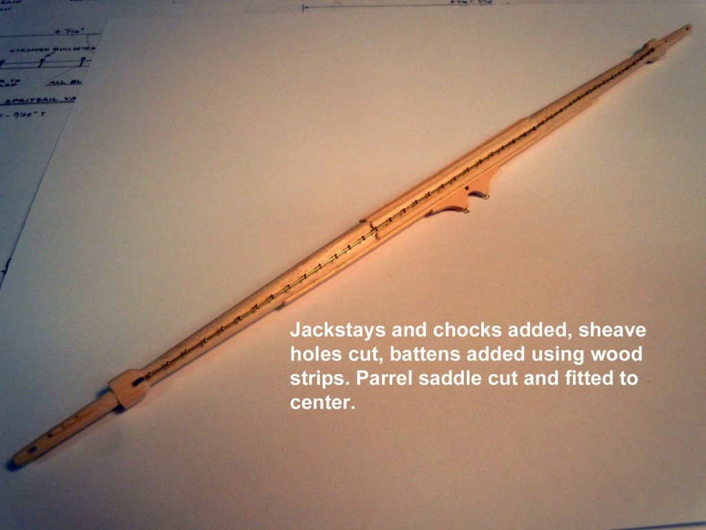
Finished up all the yards with all the jackstays and used 28 gauge brass wire stretched and indexed through the jackstays. Then cut, tapered and stained the studding sail booms and yards. Not sure if I will need the yards because I think they may be attached to the sails themselves. I then made the first set of studding sail booms hardware. The brass rings needed to be both drilled and then turned down to the sizes need from rod. The inside ring was located and glued in place first so that the end rings could be sized and located using the booms themselves. The following pictures show the process. Now that I have the first set sorted out on to making the rest. These will be stained/painted black once all are completed.
-
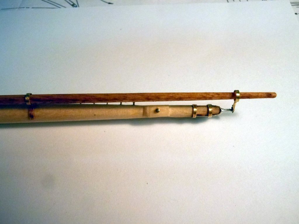
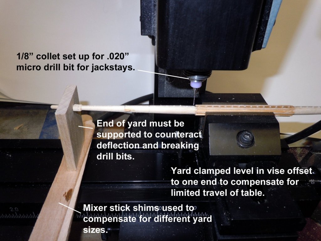
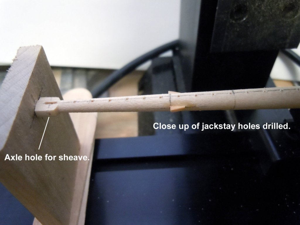
Geoff, thanks but you should not slow down your build. I have been doing more yard work and have moved on. However, I took time to set up my x-y-z table using my lather motor to drill jackstay .020" holes after my bulk pack of jack stays arrived from M.E. I am using a .020" micro drill bit which I found out quickly have no lateral strength and break extremely easily; hence supporting the end of the yard is a must. I made a quick support using a scrap piece of block and drilled a hole to slip on the end of the yard and shimmed with mixing sticks for different sizes of yards. I also realized that the vise has to be set off to one end to compensate for the travel of the table. This set up also will function as a mill with the lathe motor attached. The transfer of the motor takes less than a minute from one set up to the other. Now down the road to sneak another motor passed the admiral. Here are a couple of pictures of the set up. Holes below drilled on 3/16" centers per the plans. One thing that amazed me was how much more precise the collet set up is over a drill press at these small sizes. Now to find a source for end mills this small.
-
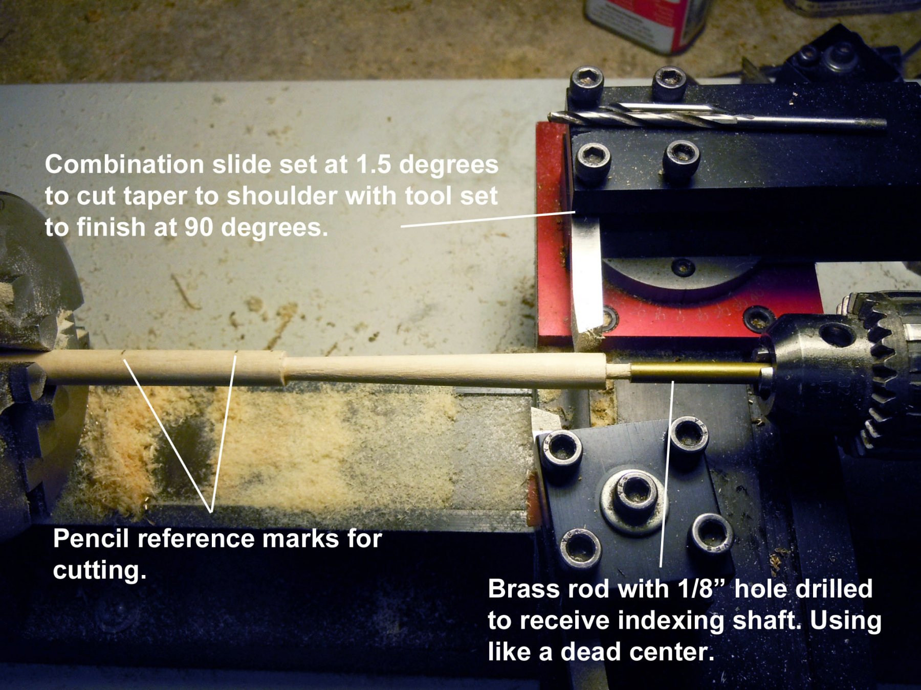
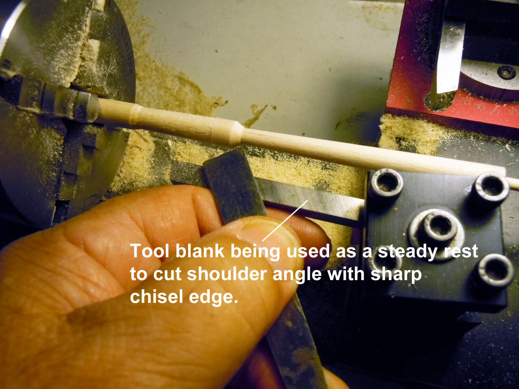
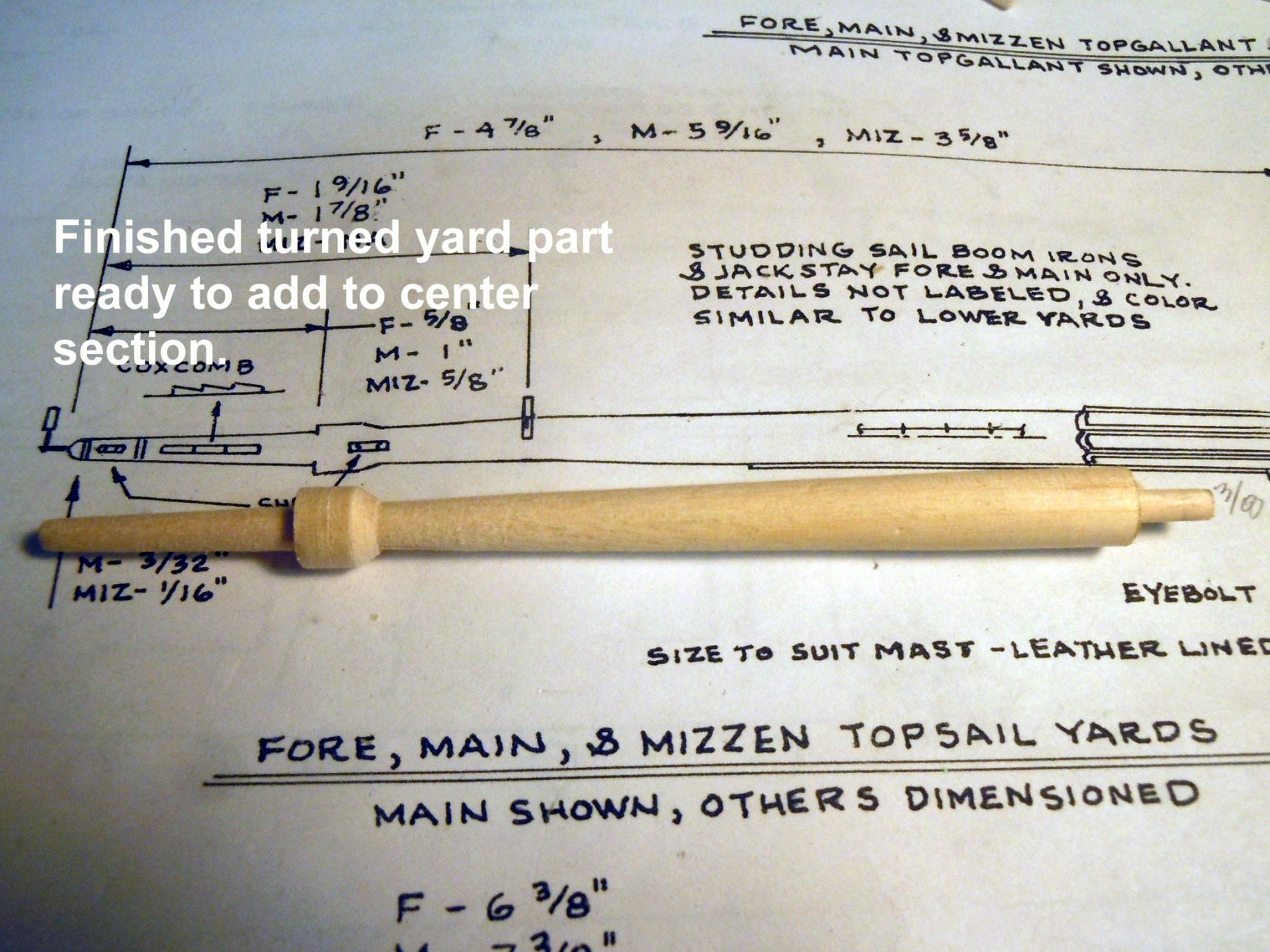
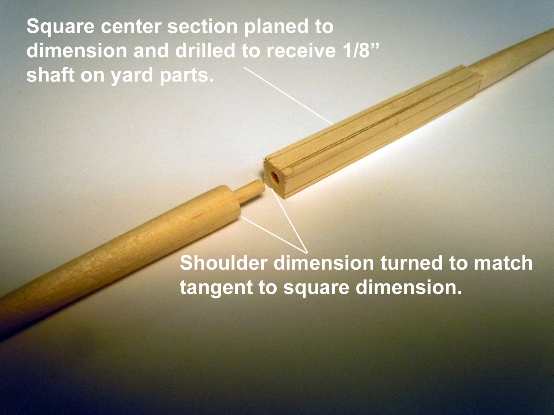
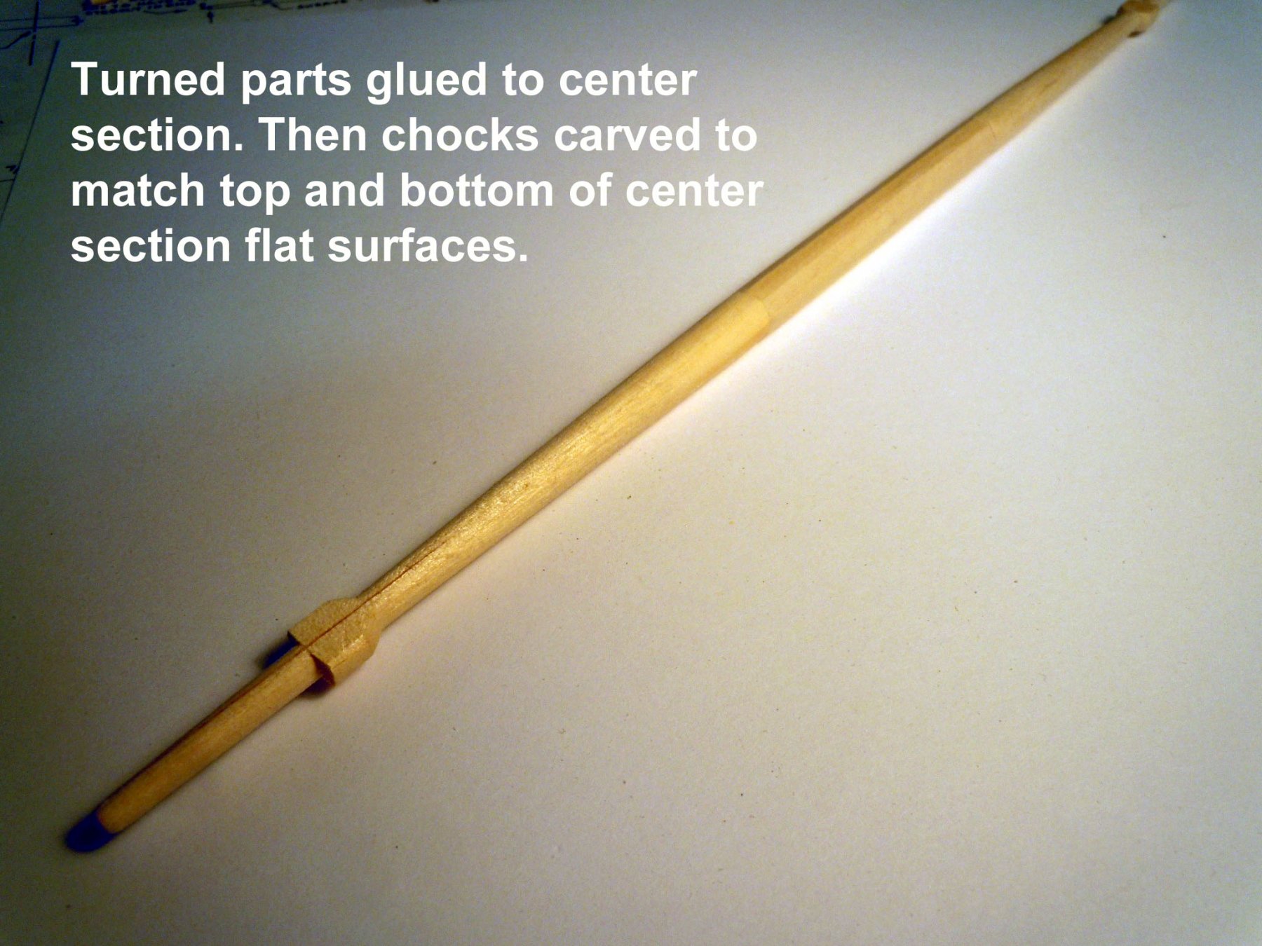
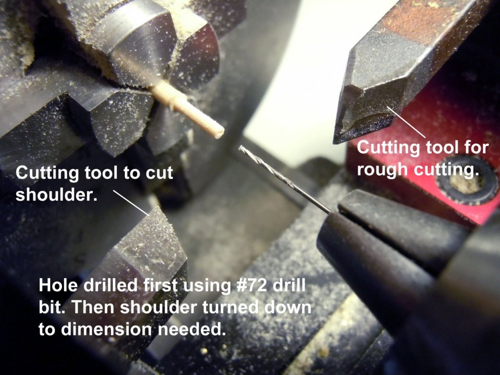
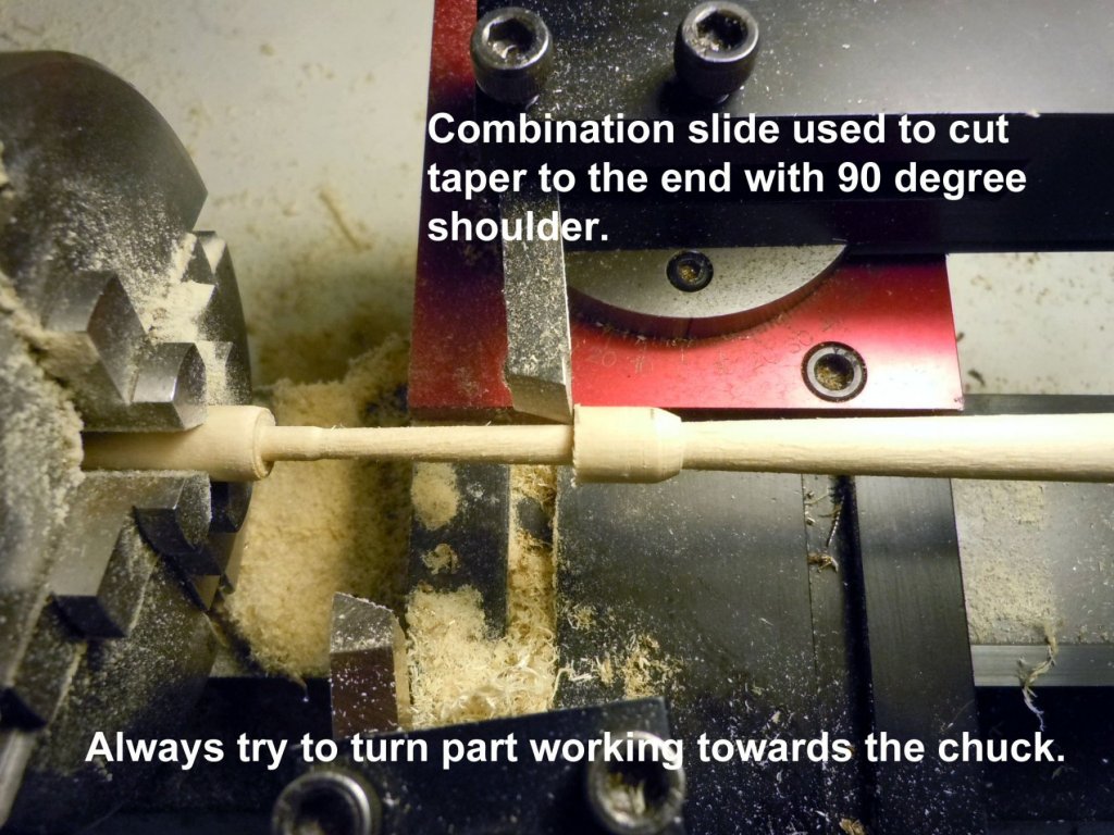
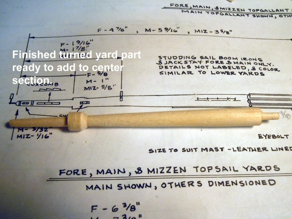
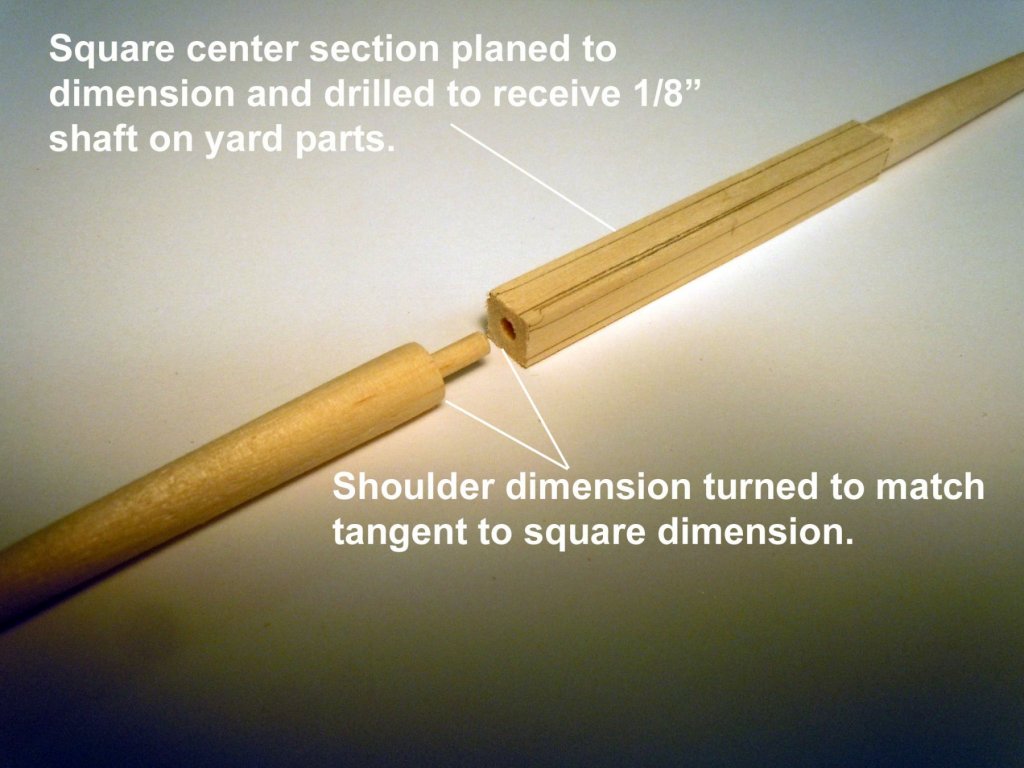
Jonathan, After my experience on the Niagara making one piece yards from dowel the challenge was getting a clean transition from the center hex section to the tapers. I was not happy with the results and decided to do it this way instead with perfect transitions and is much faster to build. Of course having a lathe and a combination slide is required. As for jackstays yes the stretched wire passes trough the eyebolt. Here is a link to the bulk pack needed from ME. http://www.modelexpo-online.com/product.asp?ITEMNO=MS0429B Much easier to buy them than make them and they are great for other eyebolt applications as well like on the ends of the yards and saddles. After the holes are drilled I start in the middle of the yard and insert the jackstay after dipping the end into a small puddle of Gorilla glue which is a 20 second set so it allows for positioning using a small rod for visual aligning with the yard. I just work towards the ends adding one at a time. Also on bright yards blacken them first before using. Here is a quick picture for you.
-
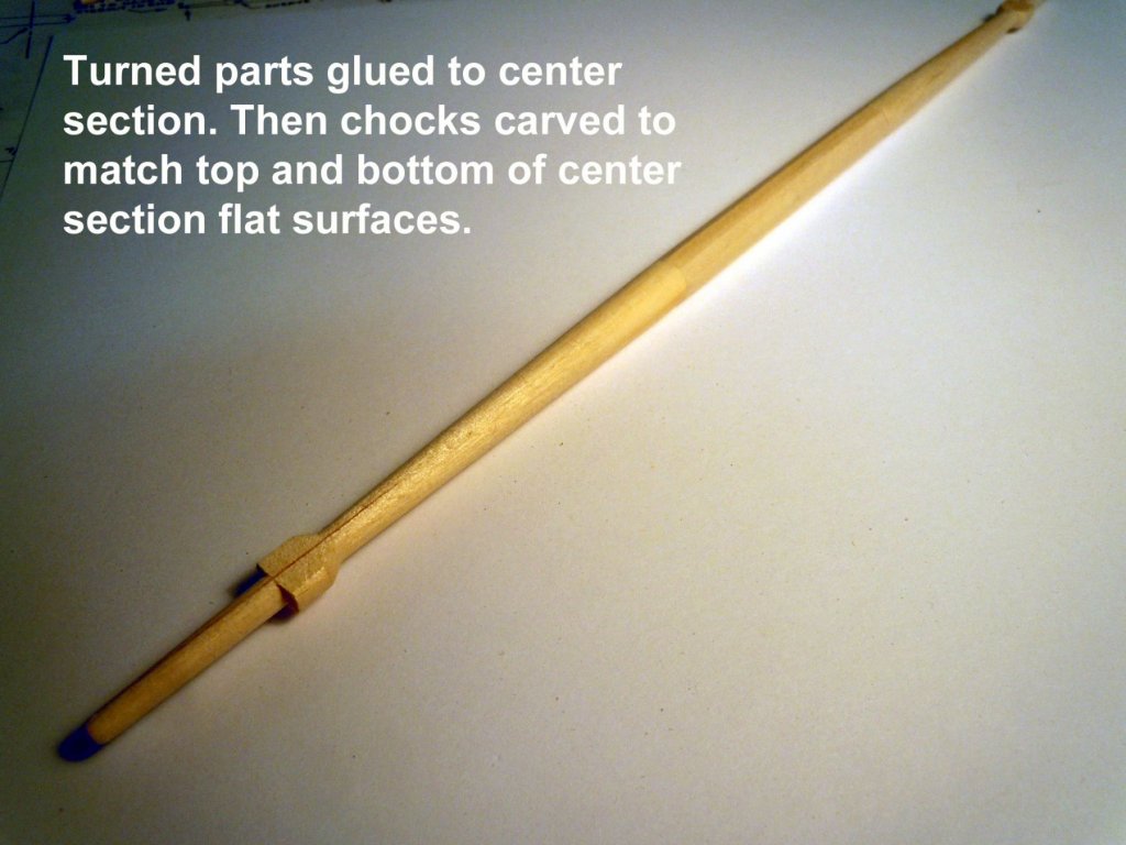
I spent Memorial Day weekend helping the wife at her Art show so not too much building; however I did start some yard work. I started with the Royals and worked my way up in size. Here is a sequence of pictures showing various building steps. On the larger yards I build in sections to have a better transition from round to the hexagon center sections. One step on the larger yards I did change was once the center square was planned to size and ends drilled I then press fit the round sections, clamped them in my vise and drilled the jack stay holes starting from the center and working out drilling to the center depth so that once turned the holes would be in place. Much easier to index and drill while still round before cutting the tapers. Now back to the larger remaining yards and waiting for more jack stays to come from Model Expo.


-
David, Congratulations on it's completion and looking great! Ken
- 117 replies
-
- 1
-
-
- constitution
- model shipways
- (and 1 more)
-
Jonathan, yes that was the one with the drawing, it provided clues on how it should be done. Making rope....so easy a 4 year old can do it! Here is my granddaughter learning how to make rope. She saw my setup and asked what it was for and then we were off making rope. She was not so interested in the first step, but the second step really peaked her interest once she could see the rope twisting. Who knows perhaps a future model builder in the making.

-
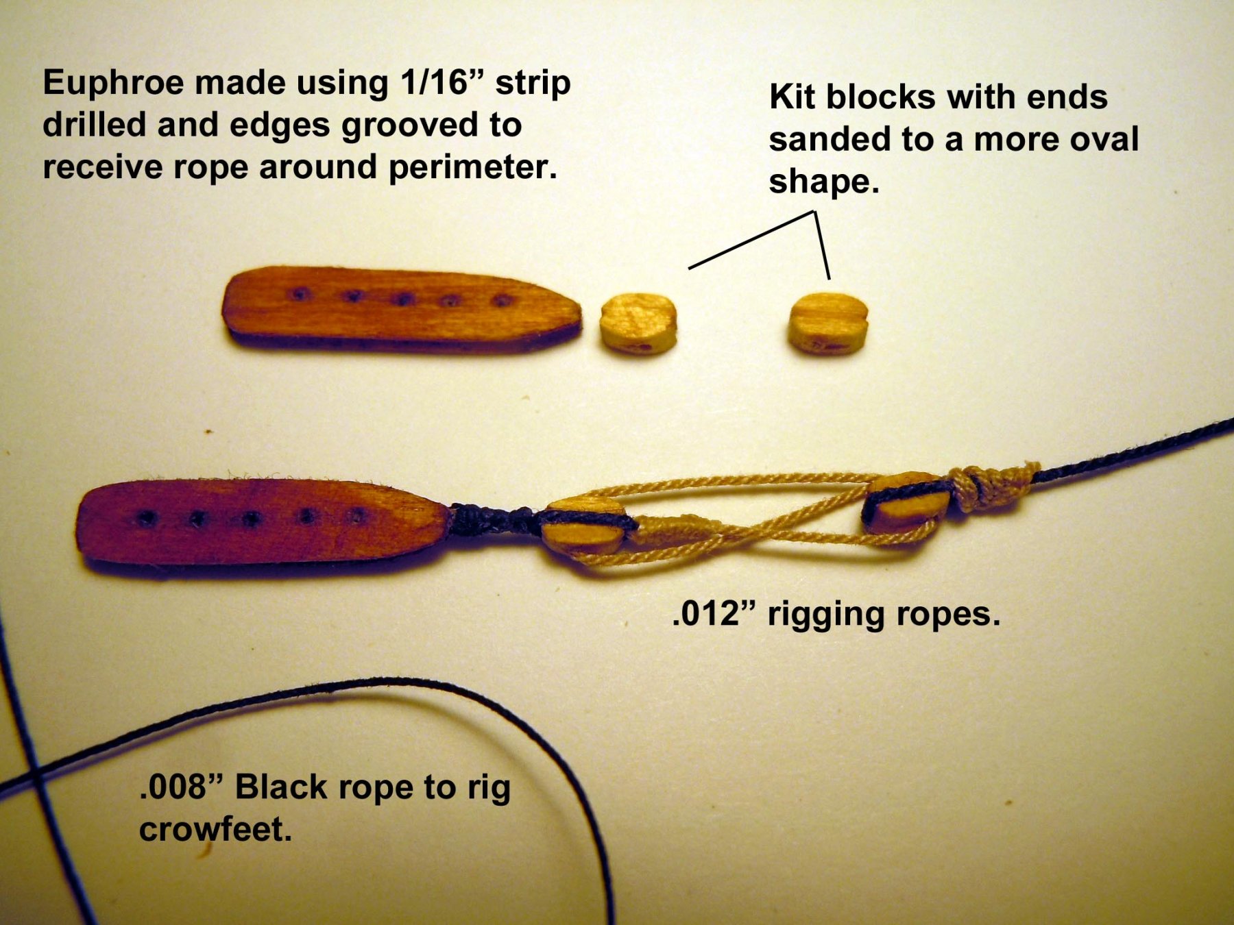
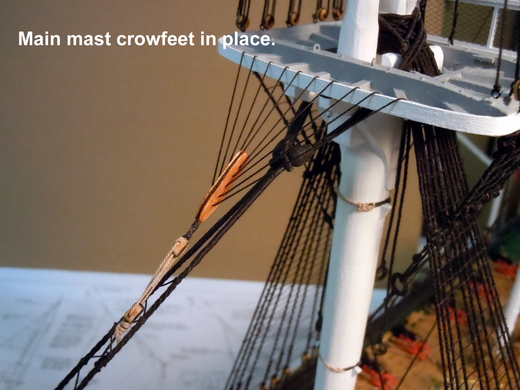
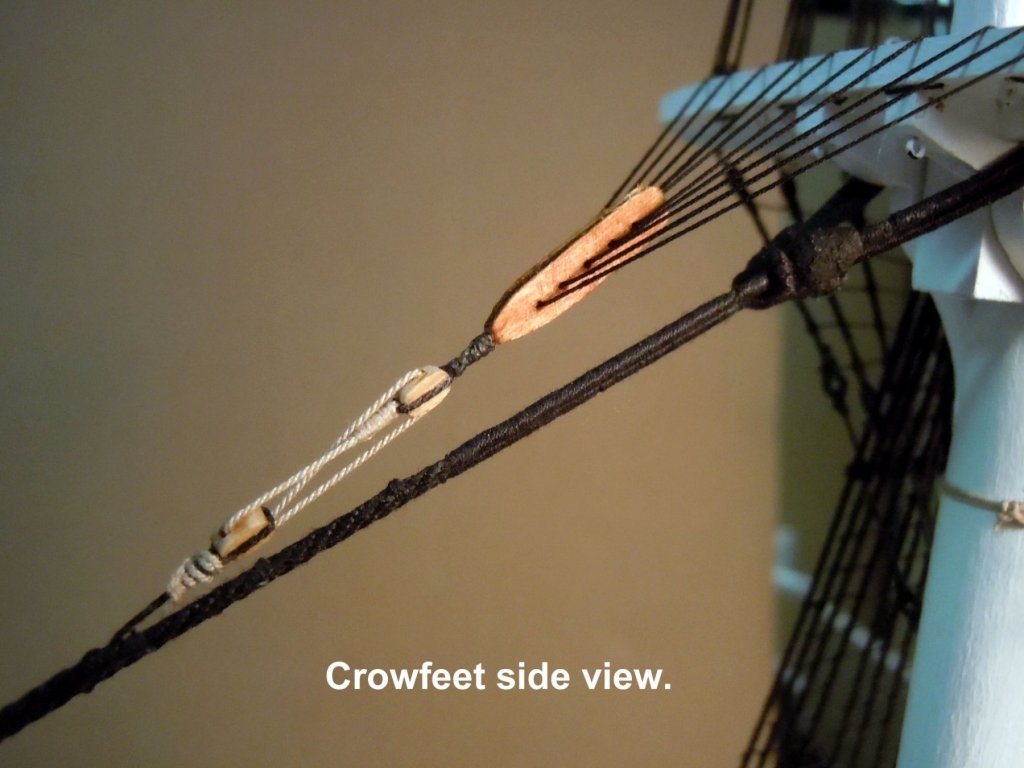
Since I am still a rookie at ship building and still learning I thought I would go the extra step and learn about Crowfeet. It did take a little research but thanks to a post by Johnathan I was able to crack the code and sequence to rig them through the 10 holes at the fighting top. I did find that there are at least two different ways to rig them and this version does not have a line coming from the top of the euphroe to the top. Once done it was well worth the effort and really adds a nice detail for the eyes to explore. Now to do the foremast.


-
Michael, nice set up. I assume though it must still be turned by hand? I opted to clamp mine to the desk top which is good enough for my purposes and using the hand drill really speeds up the rope making. I also use my lathe for serving the ropes which is quite fast now that I have the process sorted out.