HOLIDAY DONATION DRIVE - SUPPORT MSW - DO YOUR PART TO KEEP THIS GREAT FORUM GOING! (89 donations so far out of 49,000 members - C'mon guys!)
×


xken
-
Posts
841 -
Joined
-
Last visited
Content Type
Profiles
Forums
Gallery
Events
Everything posted by xken
-
 Gerald, thanks for the link to the duplicator. I enjoy your ingenuity for building the tools and fixtures as needed, “necessity is always the mother of invention”. As for hr noise it is music to my ears knowing that she is having a great time doing her work. Keep up the great work!
- 281 replies
-
- 1
-

-
- falls of clyde
- tanker
- (and 2 more)
-
I have come across all the issues identified above; but two critical are the reproduction printing process and the drawing program to begin with. I discovered the reproduction process when getting CAD drawings size D (22 x 34)reproduced for a build. The local printer did not reset the printer from a previous job and my drawings were printed at a 105% setting. Once discovered I took the drawings back and they zeroed the printer at 100% from then on on all my drawings I draw a 1 inch reference square and I tell the printer to verify the size on printing. I have not had a problem since. Also make sure the printer is using a large format printer capable of size E (34 x 44) drawings. Smaller machines when forced to a larger size often have distortion issues. Much like camera distortion in photographs. The second issue is the CAD versus Drawing program. While a drawing program is exactly what it says it is to be used for....drawing. CAD programs are for engineering drawing to at least four decimal points or more if needed. The best example to explain he difference is comparing both to a road. A drawing line is the size across the road from berm to berm while the CAD program set a .5mm line weight is like the stripe down the centerline. Admittedly, CAD programs are more expensive with a steeper learning curve versus the drawing programs. The old adage comes into play " you get what you pay for" and if accuracy is of major concern one needs to start with a good CAD drawing. One can still have errors with CAD but that usually is now human operator error not the program. As technology has evolved with 3D printing and laser cutting machines for hobbyists, to appeal to more they can use drawing files to work with their machines which usually have some form of conversion program to work. As a parting comment I would say that we are building models that probably will sit in a case and never be measured for comparison to another and can only be as good as the reference material we are building from. My experience has been that all kits and plans have accuracy issues and common sense adjustments are required and enjoy the build process.
-
A lathe for masts and spars
xken replied to Don Quixote's topic in Modeling tools and Workshop Equipment
I have the 4400 long bed Sherline lathe and have used it for both masts and yards. Check out their site they now have a lathe setup for pool cue manufacturers along with an extended live center (new product) which I plan on buying. One thing with working with a lathe with wood is the type of wood being cut. Hardwoods are best, softwoods tend to shred rather than cut. I use mine primarily for metal and occasionally for wood. Keep in mind you can always turn wood with a metal lathe, but you cannot turn metal with a wood lathe. Just my 2 cents. -
Dave the boats are looking great and that you are having fun with all the details.
- 742 replies
-
- 5
-
-
- constitution
- frigate
- (and 1 more)
-
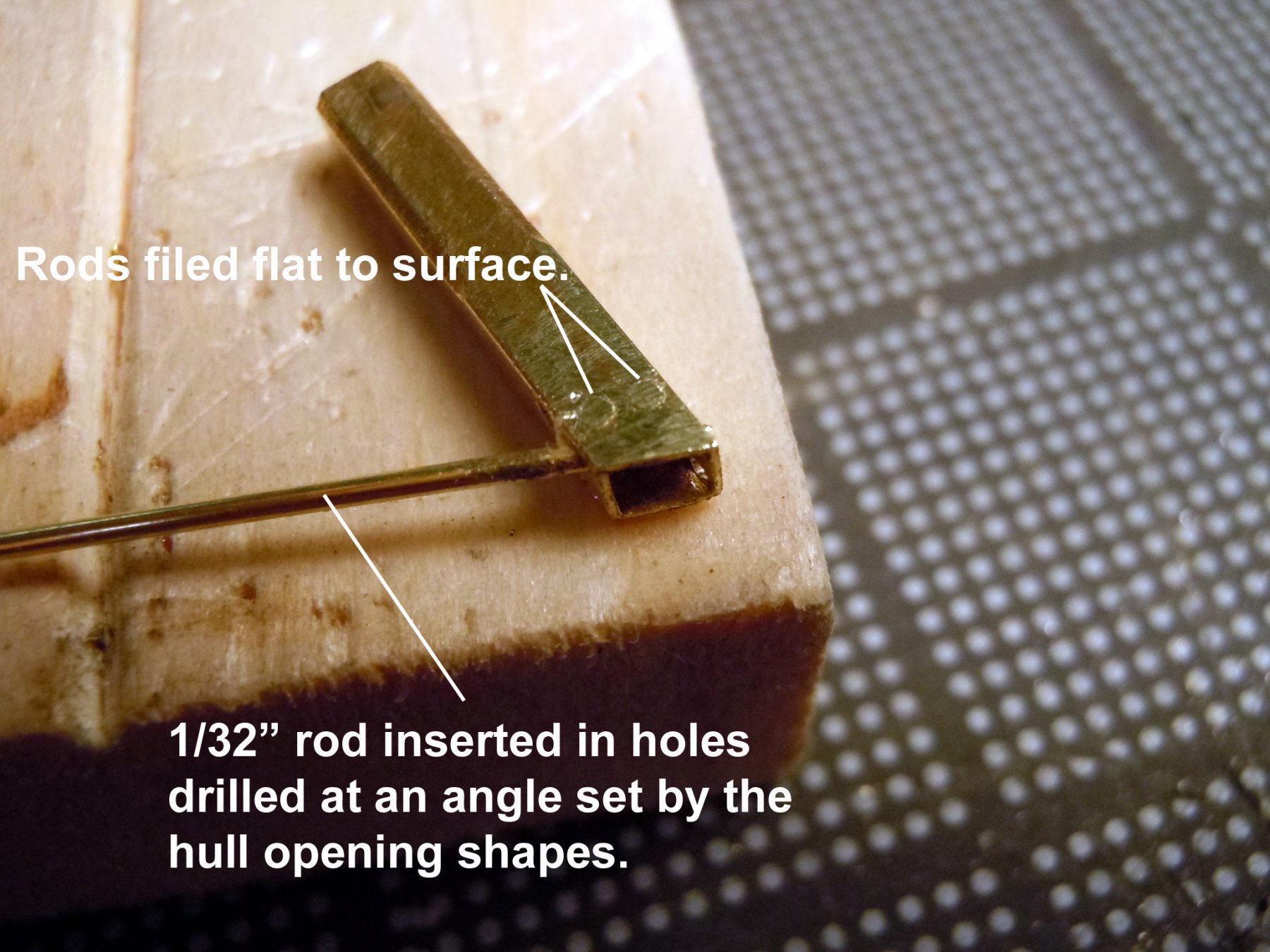
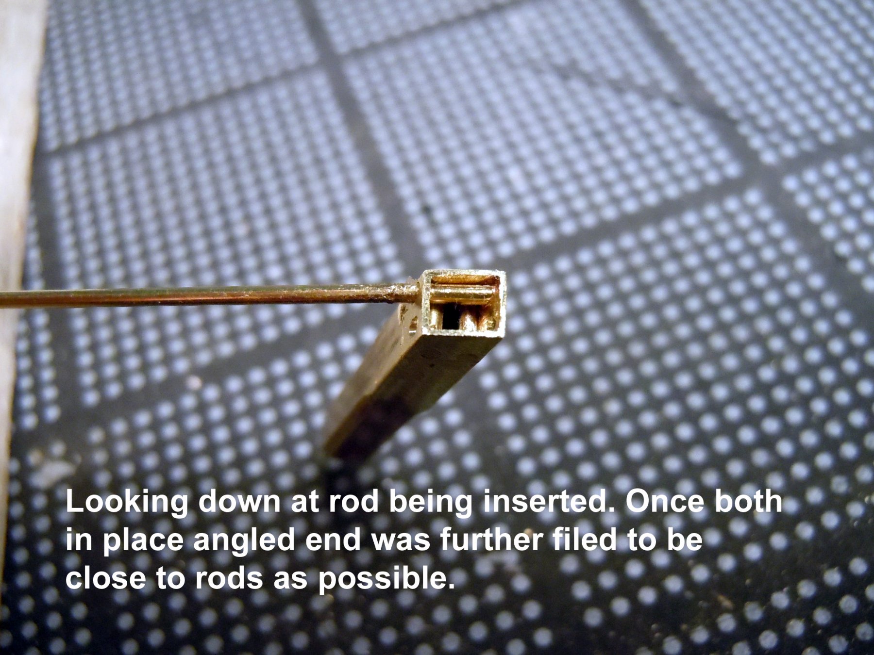
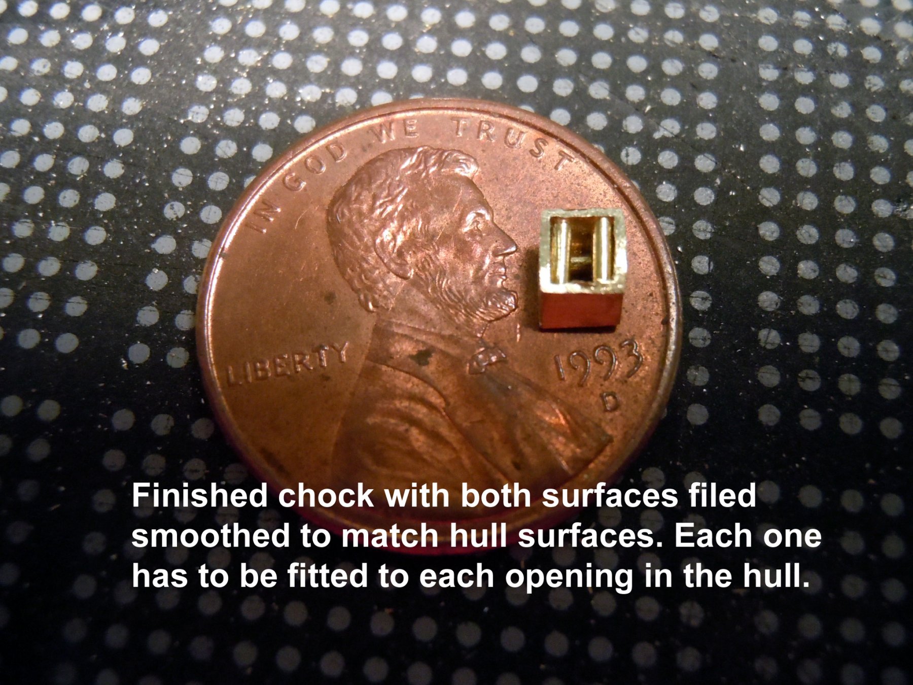
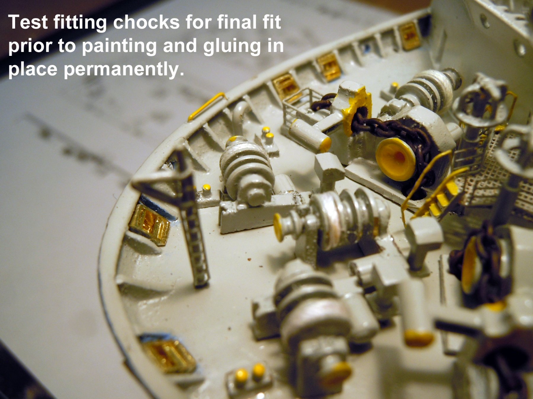
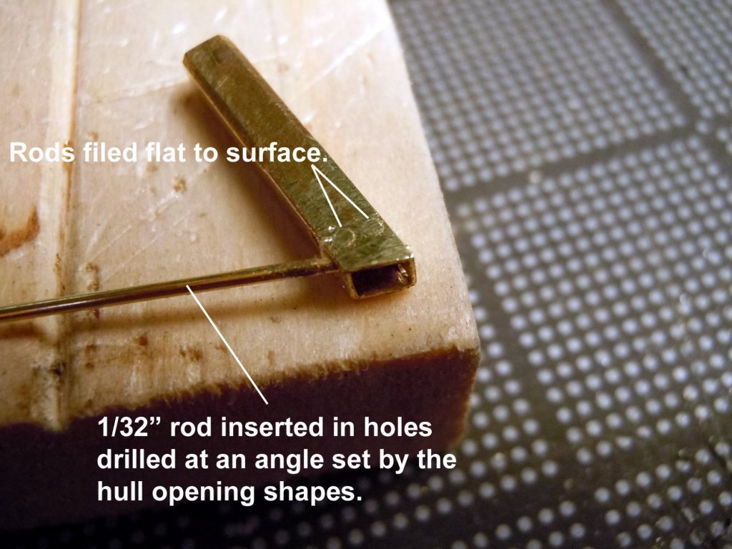
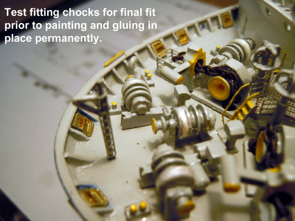
Taking a break from CAD drawing on two new projects; after awhile the old eyeballs start doing barrel rolls so to break away from the screen I bounce back to working on the ship. Here are a few images of making the bow chocks which have both horizontal and vertical rollers. The challenge was fitting each to there respective hull locations with different angles. First was starting with square brass tube and inserting it into the opening in the hull and scribed a line on the external side of the hull. Then drilling two holes and inserting rods and cutting and filing smooth. Then two additional holes drilled and then filed to fit. This shows the size of these chocks. Here they are for final fitting. Now back to more CAD drawing.


-
Gerald, always a joy to see your work and the how to explanation. I especially liked your comment about silversmithing; I married one and have watched her hammer an 8 inch disk of 1/8 inch thick silver into a cocktail pitcher 11 inches high with no seams. At the other end she has Hammered cowls for my WWI planes using .020” aluminum. It is always a joy to watch her work, even if she is a little noisy. Keep up the great work and sharing of your talent.
- 281 replies
-
- 2
-
-
- falls of clyde
- tanker
- (and 2 more)
-
Nils, the crew look great and really add a sense of scale.
- 692 replies
-
- 3
-
-
- eagle of algier
- chebec
- (and 2 more)
-
Jack, Thanks, for the explanation. John here is an image as well as a PDF file of the working CAD drawing I will be using when time to start building. Yesterday I had a chance to see the museum building under construction ready for interior painting. The opening is planned for October to coincide with the Harbor Festival. The build is on hold for now until the building is complete due to budget constraints. But if I wish I can start at my own risk of not being paid for some time. I also have just been asked to consider two commissions for ME which will take priority at this point. Here is CAD drawing: LCVP PLAN01.pdf
-
Kurt, I sent you a PM about the article and payment. Thanks to both Roger and Kurt!
-
Roger, do you remember the year or the Journal numbers of the series?
-
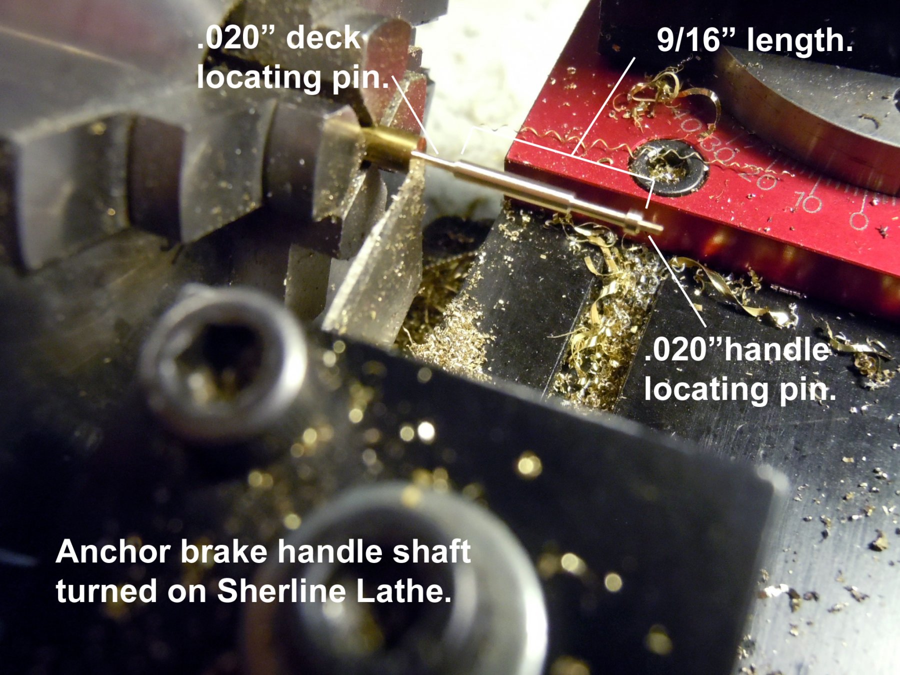
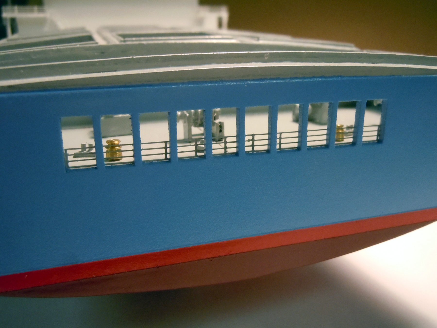
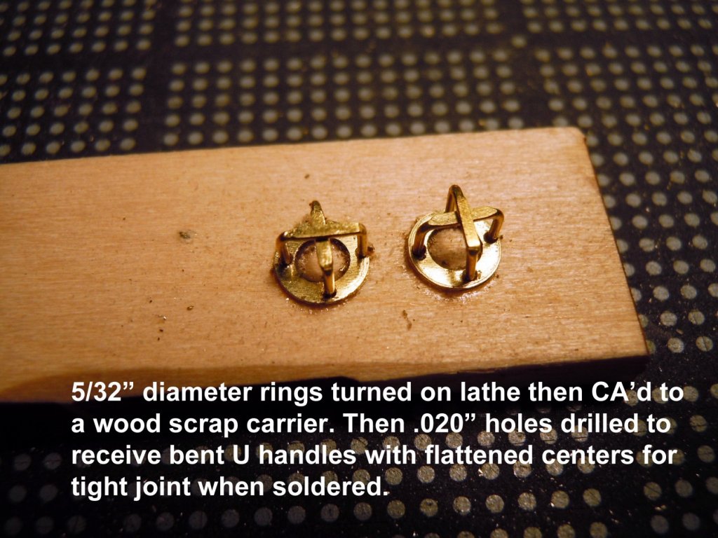
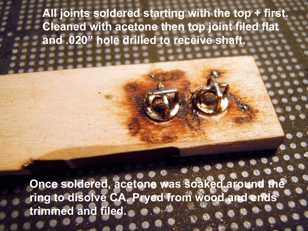
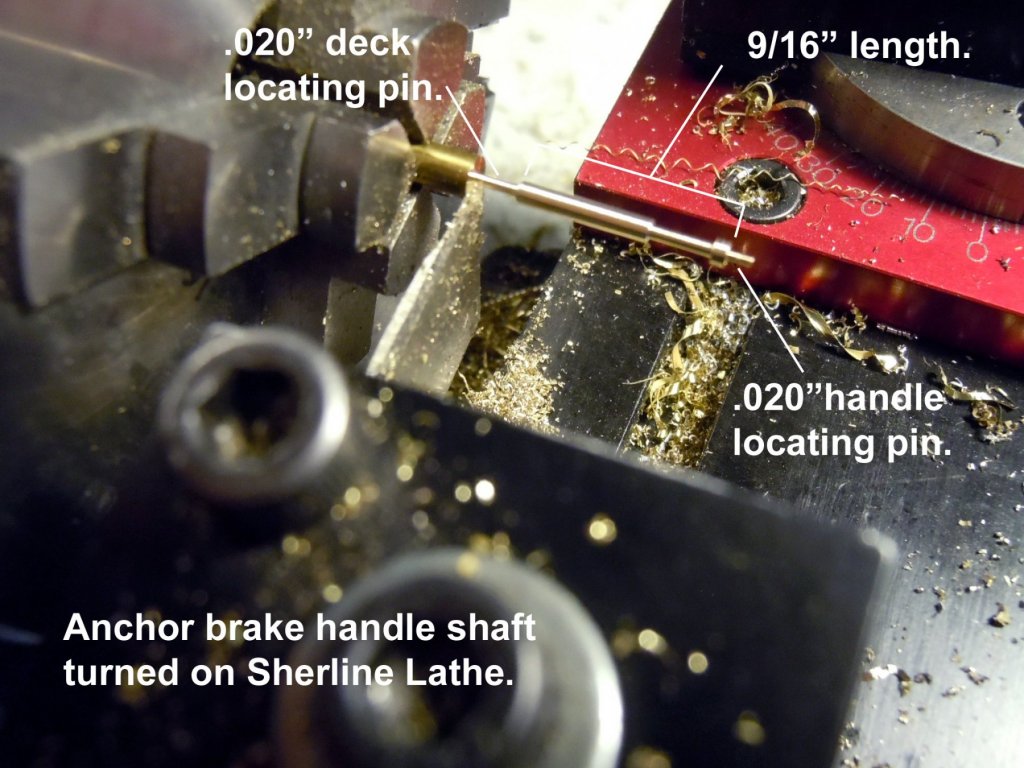
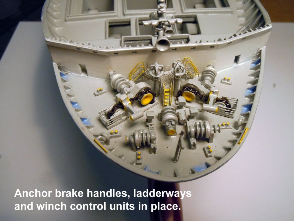
A quick update to show the bow mooring deck with the emergency hand operated anchor brake handles in place along with the ladderways on either side. Evan said that the brakes are normally electo-hydraulically operated and that the handles rise up and down with the anchor chain mechanism, hence the U shaped handles. I thought I would share the steps to make these small handles and how they were soldered while indexed into horizontal ring. Here is a unabashed plug for why I love the precision of my Sherline lathe turning down .020" locating pins on the handle shaft. My cutting tool is a parting tool ground down to a 1/32" cutting edge. Here they are in place. Evan said that the ladderways allowed quick access from the deck sides or front if a winch failure happens. Now to the rope bollards for both mooring decks. Still waiting to hear back about the LCVP project; may end up another hurry up and wait project.
-
Great machines that I use on a daily basis and would recommend to anyone. I cannot imagine trying to do a super detailed build without them. I even use my lathe to seize shroud lines. Glad they are on board!
-
Ken, thanks for the link and your assessment is correct a little too course, but will save for future reference.
-
Cathead, I have to add a few more details there are two ladderways to be added at the end against the bulkhead and two wheels that I think work the anchor brakes while standing on the platform. Standby more to come.
-
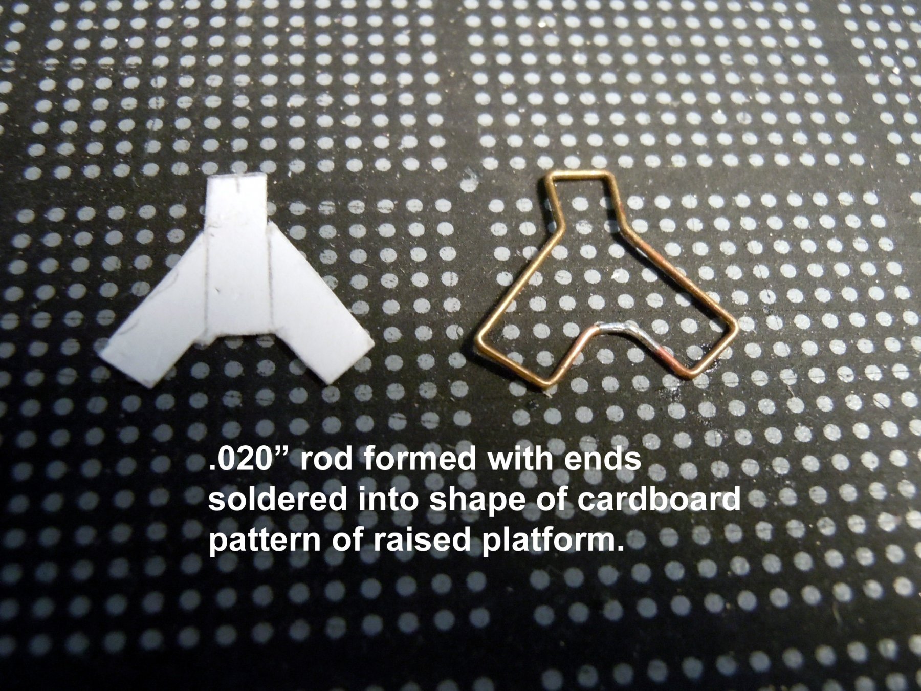
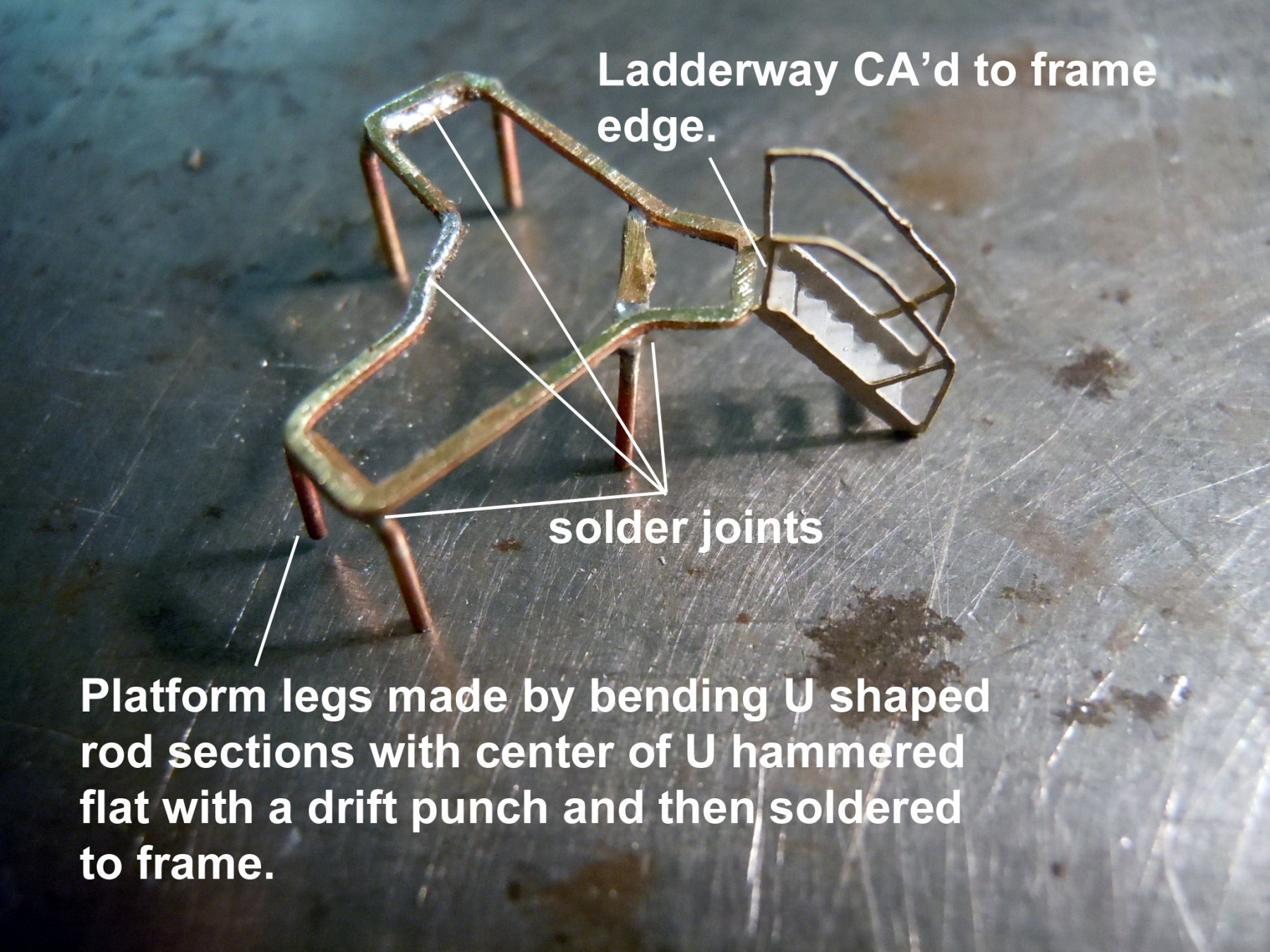
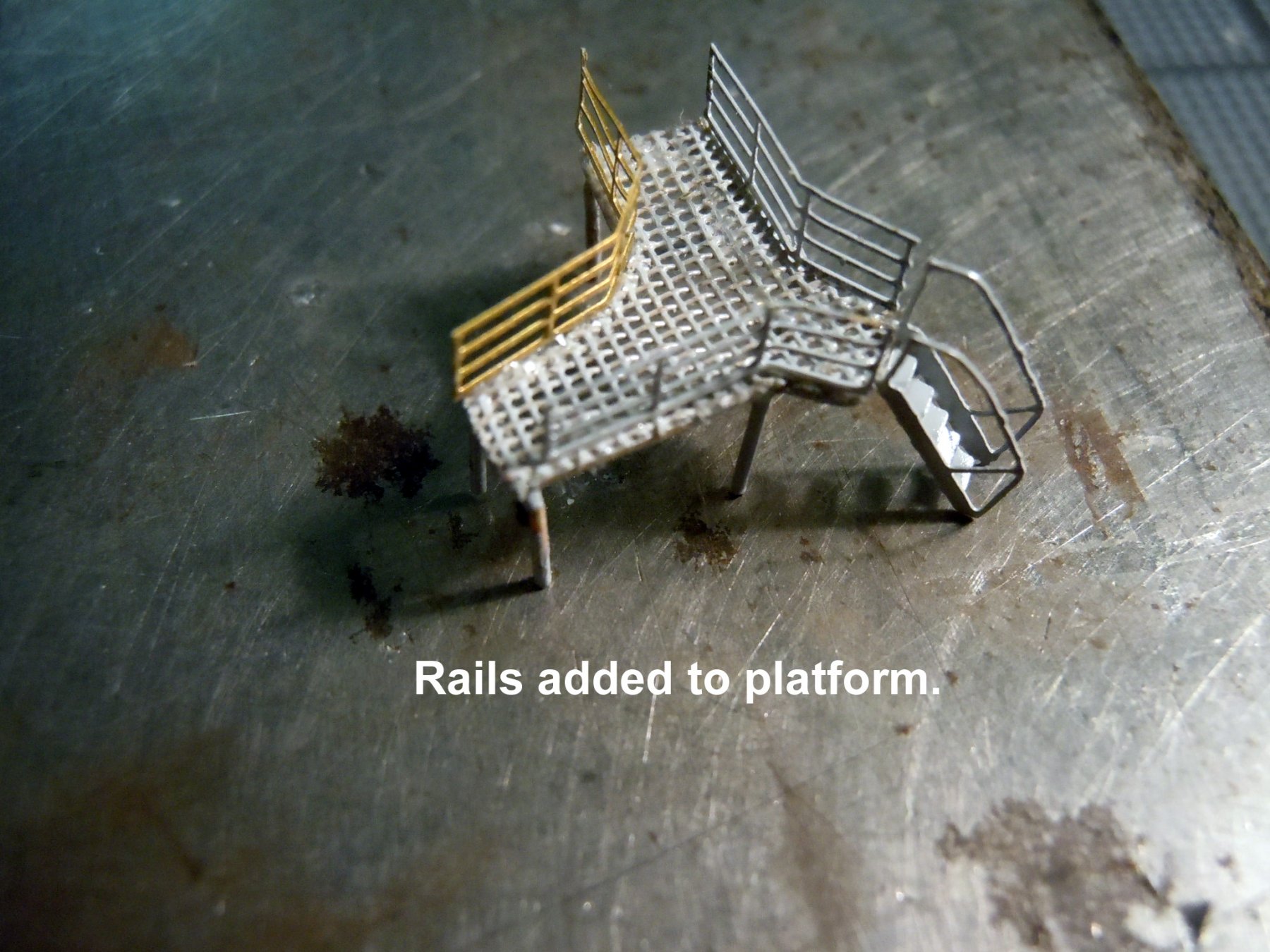
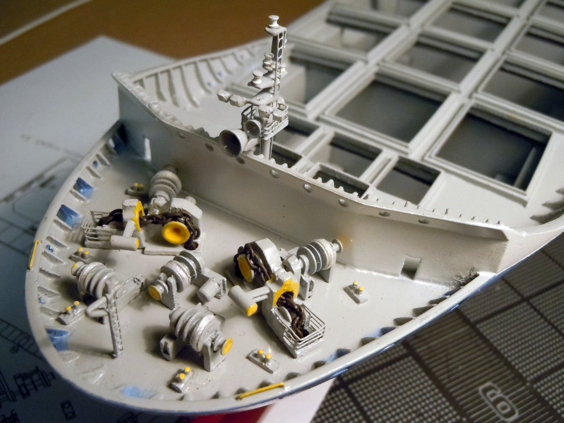
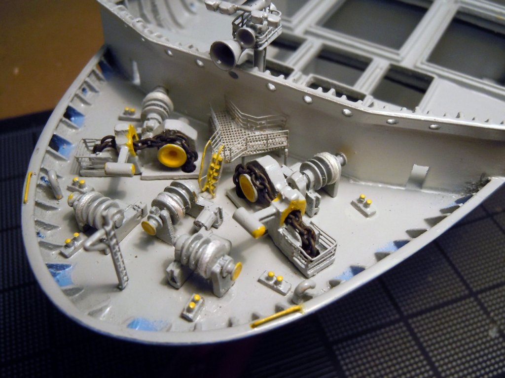
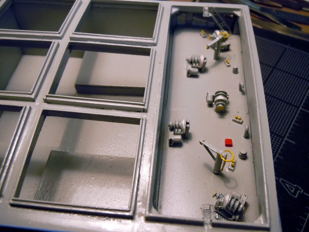
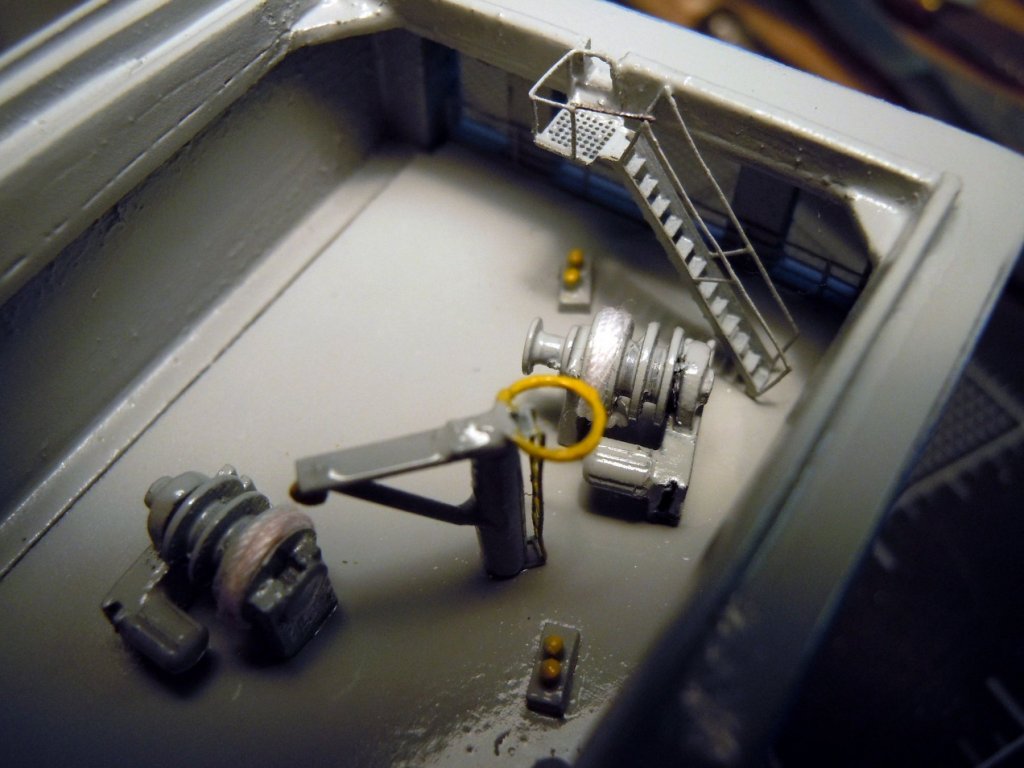
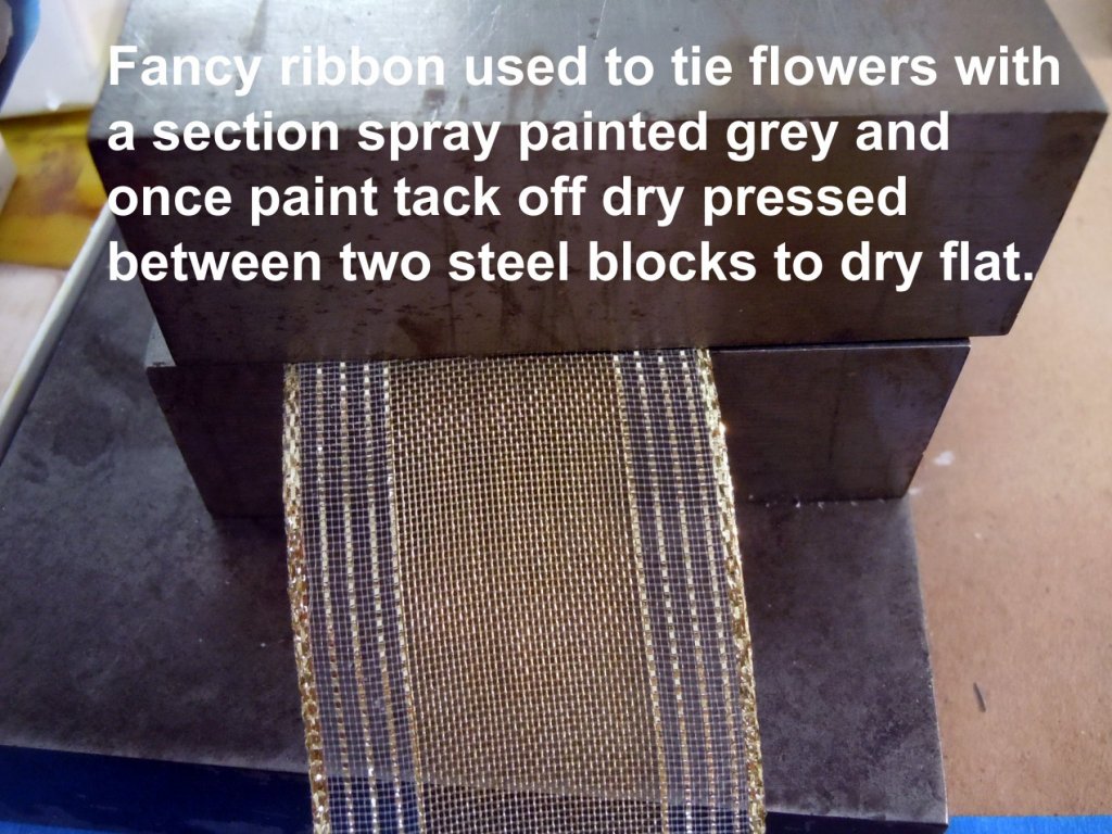
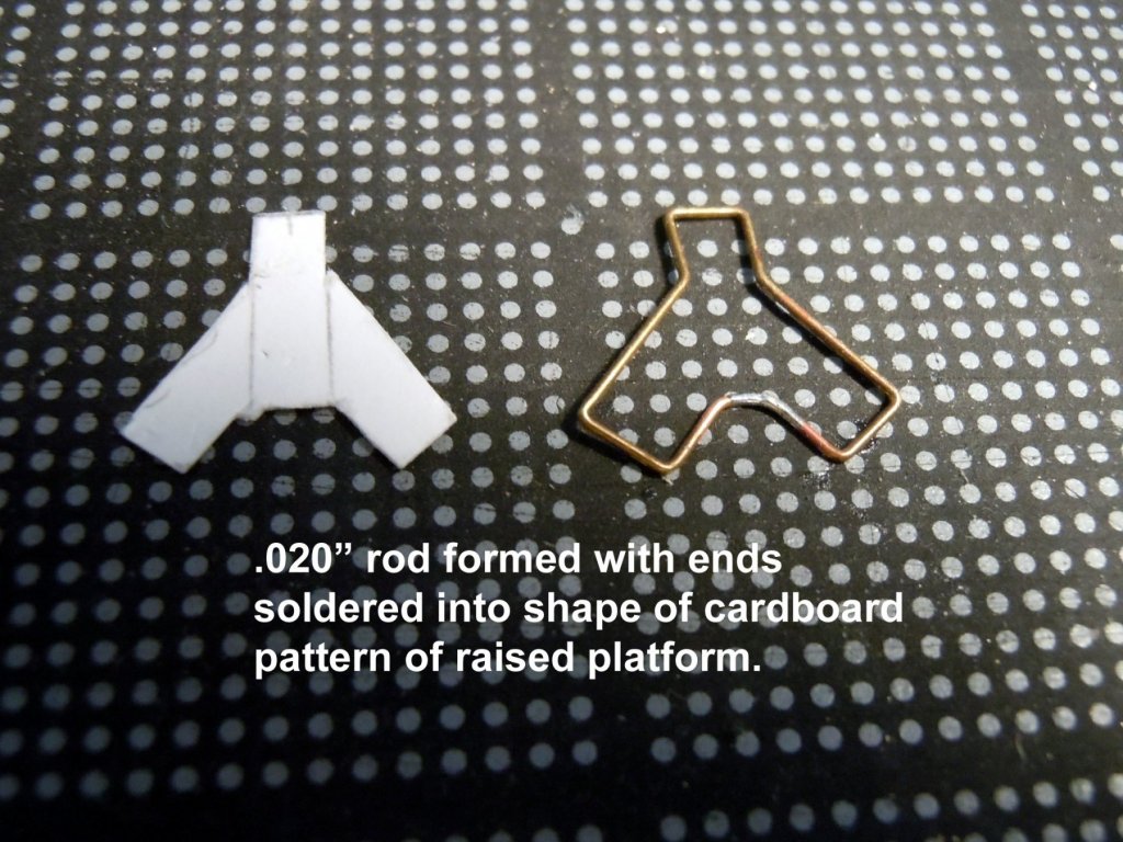
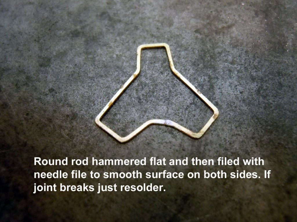
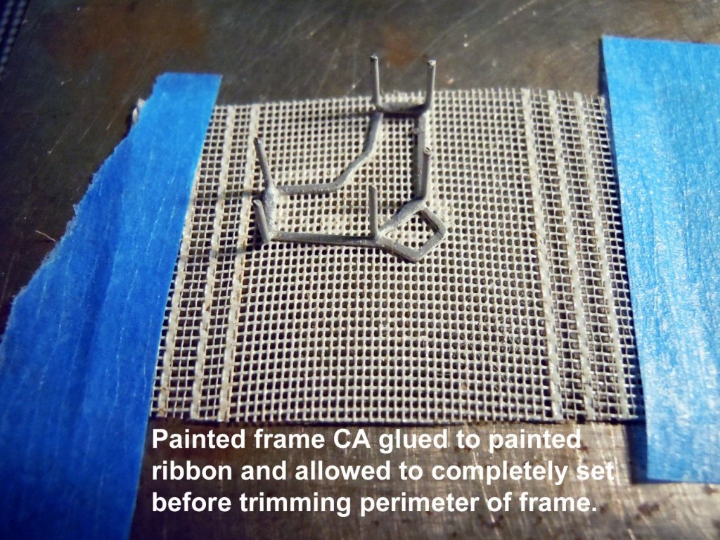
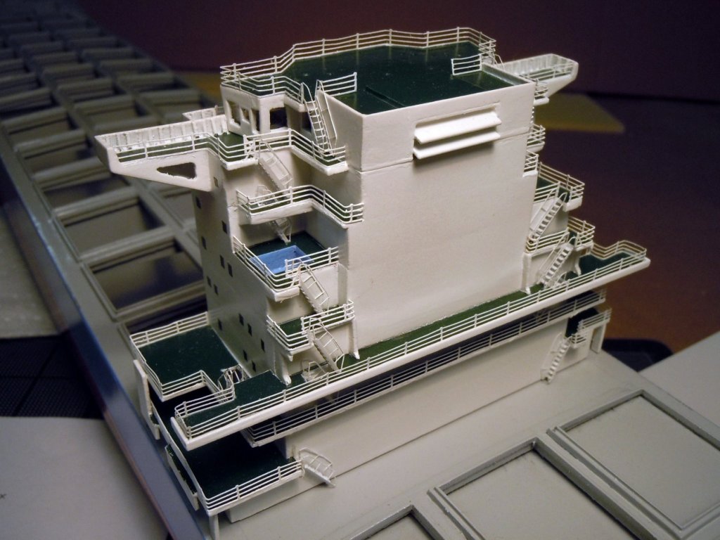
I have been working back and forth between the bow and stern mooring decks working on the various items. Here is a picture of the stern mooring deck. Here is a close up of the ladderway on the starboard side formed from one of Tom's PE sheets. Also note some yellow caution paint on some components which I added per photos. One of the more challenging items was a raised platform between the anchor winches that has a meshed floor. My wife had some ribbon that came on a flower bouquet that I liberated from her. I sprayed a section with gray paint let it tack off and then pressed it between two steel blocks to set flat. Next I cut a pattern of the platform floor and bent a .020" brass rod around the perimeter of the pattern and soldered the joint. I then hammered the formed shape flat and then filed it smooth on both sides. Next I bent three U shapes for the legs and hammered the center flat for a mating surface with the frame when soldered together. Once all were soldered in place the legs were all cut to the correct length needed. I then glued a formed ladderway to the edge of the frame and allowed the glue to really set hard. I then sprayed the platform frame with gray paint and using a medium thick CA glued the frame to the painted ribbon. Once the glue set I carefully cut it out around the perimeter. Next came the rails cut and fitted to the frame and then the painted with the ladderway rails and steps painted yellow. Here is the platform in place along with the rest of the fixtures on the bow mooring deck with the various yellow caution highlights. Now back to adding more details.


-
Nils, this is a great build log to follow and one can see and share in the fun you are enjoying adding all the great details to this build. Keep up the wonderful job and continue to have fun.
- 692 replies
-
- 5
-
-
- eagle of algier
- chebec
- (and 2 more)
-
Model Shipway Ratline tool
xken replied to fnkershner's topic in Modeling tools and Workshop Equipment
Doug, I like your idea of adding the guide rails for the white background card. I just cut mine to press fit. I agree with wefalck that your ratline could be thinner and be easier to tie. Again I used 100% cotton for both and tied my own ropes; polyester and nylons seem to have too much spring back for tight knot tying. Great job and I agree with you on the ergonomics of using it. -
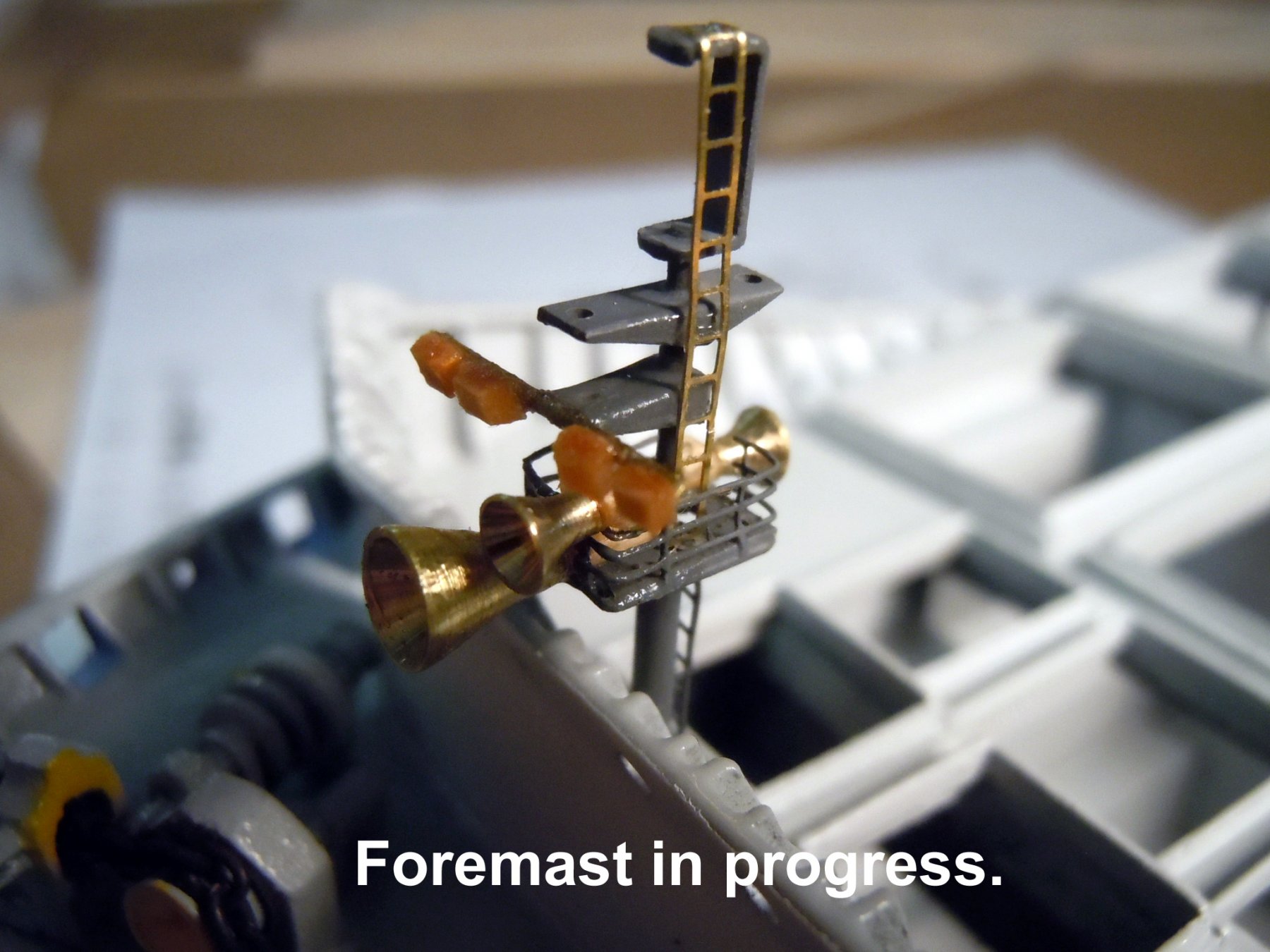
After a weekend of helping the Admiral at her Bird Festival Show selling her artwork as grunt labor I am now back to work. I am working back and forth between the bow and stern mooring decks along with the foremast. These parts are a combination of brass and wood materials as appropriate. Here is a picture of the foremast showing parts prior to painting and adding the signal lights. The wood blocks are flood lights that light up the area in front of the bow. The large horn id the fog horn, the smaller facing forward id the ship's bell and the rear facing is the loud speaker for bridge commands to the decks. Here is an in progress bow mooring deck with the winches in place with white ropes and yellow caution painted areas. Here you can see the lights have been added and lenses painted white. I still have to add the rope guides at the openings as well as the platform between the two anchor winches. Now back to more fittings.


-
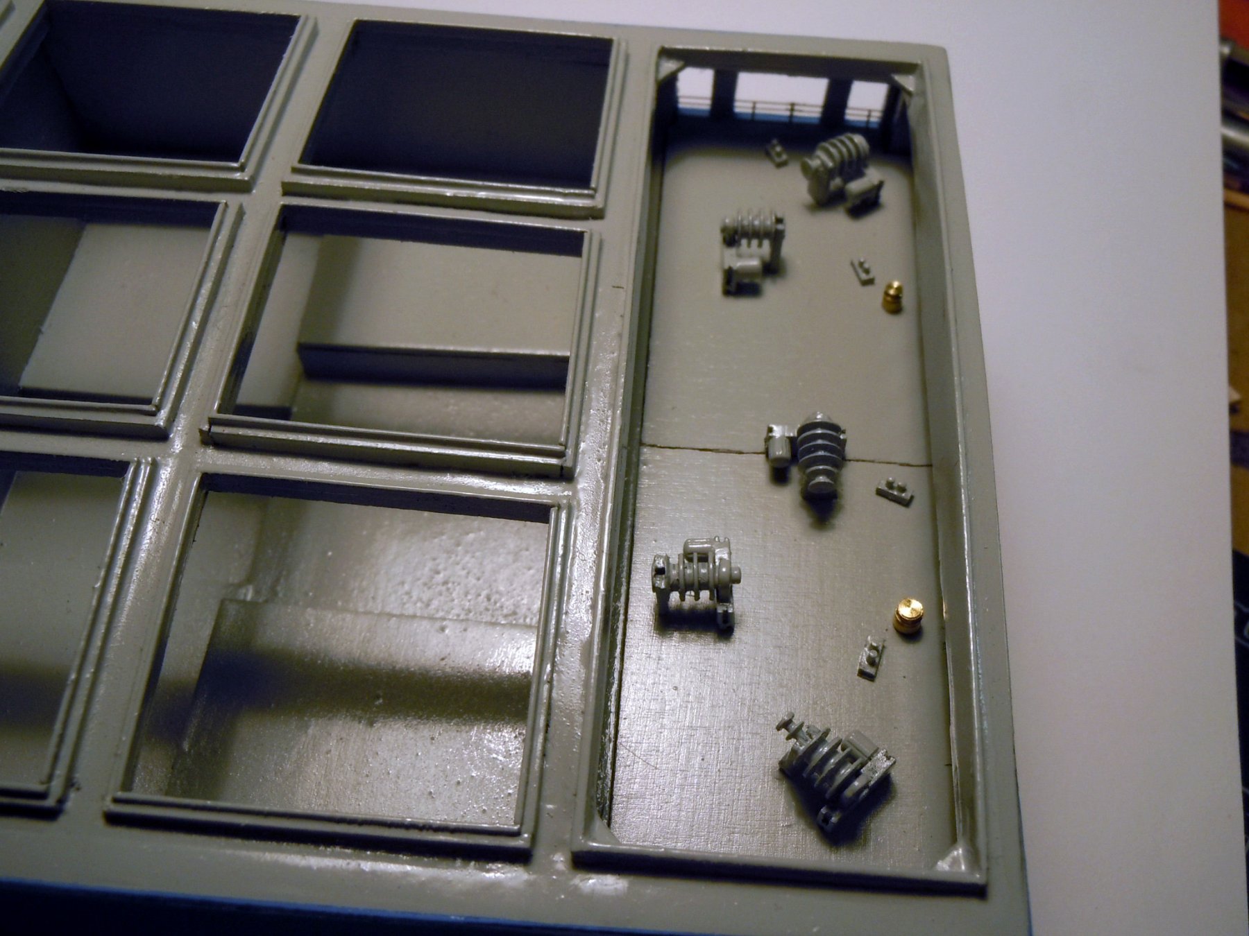
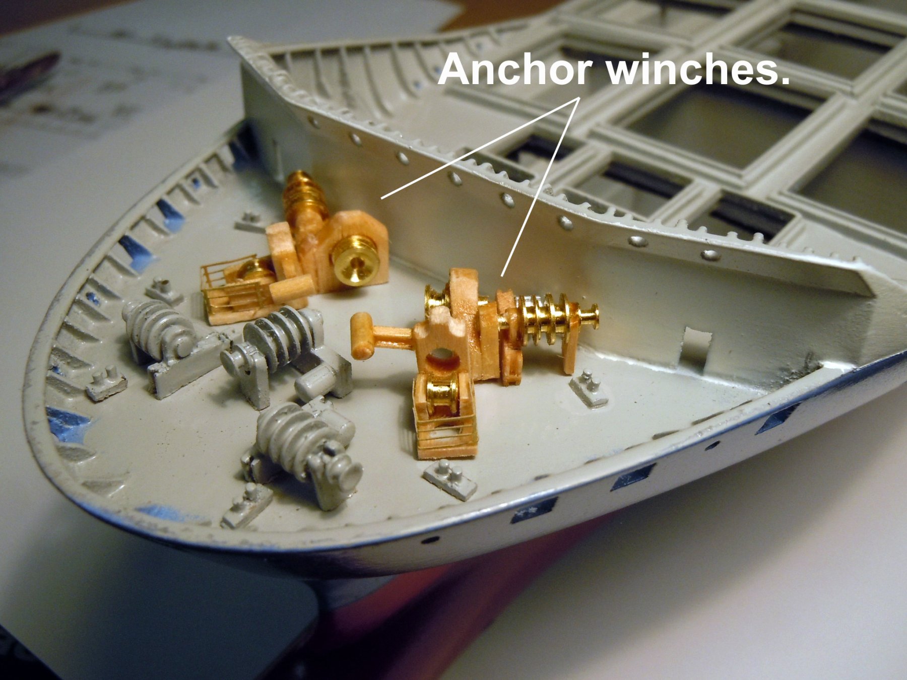
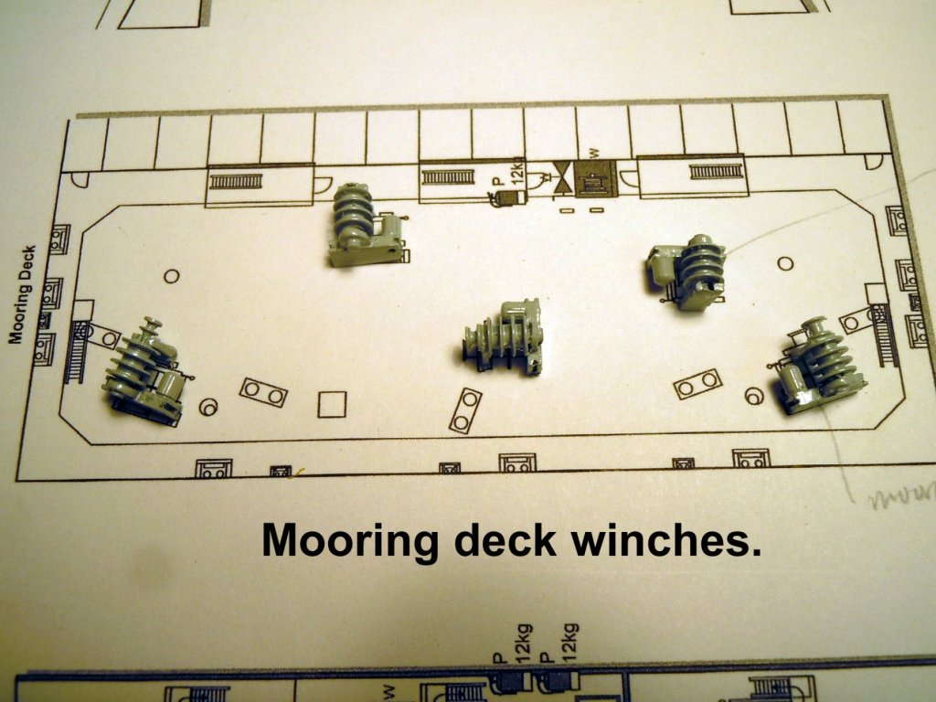
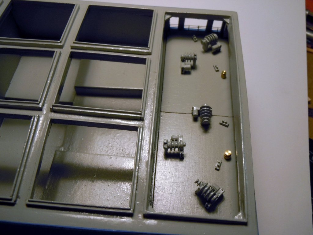
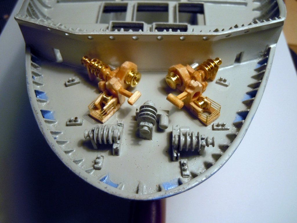
I finished up the ladderways and then added the mooring deck rails. Next I made the mooring deck winches of which there are two styles, as well as left and rights based upon the electric motor location. Here they are set on the plans. Here they are set on the deck with bits and mooring posts. White rope will be added before the winches are glued in place. Next I moved on to the bow that has three winches the same as the mooring deck; in addition there are anchor winches and the pictures show "in progress" anchor winches in place on the bow fore deck. The anchor chain will index into the hole with the brake arm over the roller and into the deck. Just a great deal of more details and fixtures to add yet.


-
Model Shipway Ratline tool
xken replied to fnkershner's topic in Modeling tools and Workshop Equipment
Doug, I have not tried that to see if there is any difference; but I am sure that the yellow color of the glue may have so level of tint when applied to brown rope. I have only ever used the white glue for this kind of application. -
Model Shipway Ratline tool
xken replied to fnkershner's topic in Modeling tools and Workshop Equipment
Doug, I did not have access to all ship plans, and it appears that the PdN is more the exception than the norm. The 1:35 size would handle the height but would require a little fussing on spacing the ratlines as they are added. Also keep in mind the shroud line spacing can be slightly adjusted by rotating the knot on the lower tabs from left or right to center on the tab. Michael, you need to make a port and starboard set; then the shroud loops can be added by alternating each as needed indexing each as they are added to the mast. Once in place then the deadeye ends can then be addressed. The key is tying the loops to keep them in proper order before removing from the Ratliner. One other thought that I have not tried is painting the lines while still on the Ratliner using either thinned paint in the case of black lines or using a 50/50 mix of white glue and water to stiffen for easier handling once removed. Perhaps Doug could do an experiment to see if it helps any. -
Model Shipway Ratline tool
xken replied to fnkershner's topic in Modeling tools and Workshop Equipment
Derek, in the instructions there is an option to bypass indexing the shroud lines through the holes and tying directly to the bottom tabs for a little extra length if needed. Sometimes you just need that extra inch or so. -
Model Shipway Ratline tool
xken replied to fnkershner's topic in Modeling tools and Workshop Equipment
Doug, looks like you are off to a great start; and practice will help. One thing to do is stretch the line before starting and use 100% cotton for best results. I made all my own lines on ME’s highly modified ropewalk that can be seen in mt Constitution build. As for your issues when tying the left side, tie a clove hitch which you can tighten and snug up with tweezers then follow up with a half hitch tied back through the rat line and seized on the tab to tighten more. The real key is to have all lines as tight as possible when starting. Three sizes are needed to best satisfy the range of model scales. Height difference from 1:35 versus 1:96. Ratline spacing is quite different. One can also drill a new pattern off indexing holes for a specific application and still tie off on the lower tabs Question 2: A odd or single shroud can be seized like a double line and then positioned as needed. Question 3: use clove hitches and with a half hitch if necessary and knot tying practice. Question 4: May need to make a rigging fixture to hold the deadeyes when tying off the shroud lines to them. To add your finished assembly to the mast you may have to cut and pin to relocate the mast after installation. That or debond the joints to disassemble. That will be a choice to ponder. I will enjoy following along and appreciate your feedback, but it looks like you are off to a great start! -
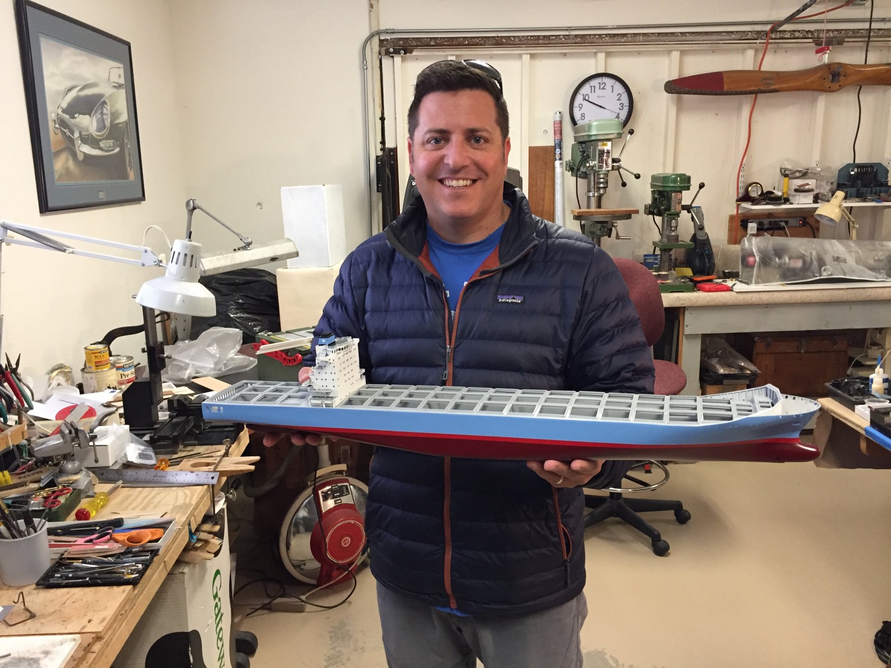
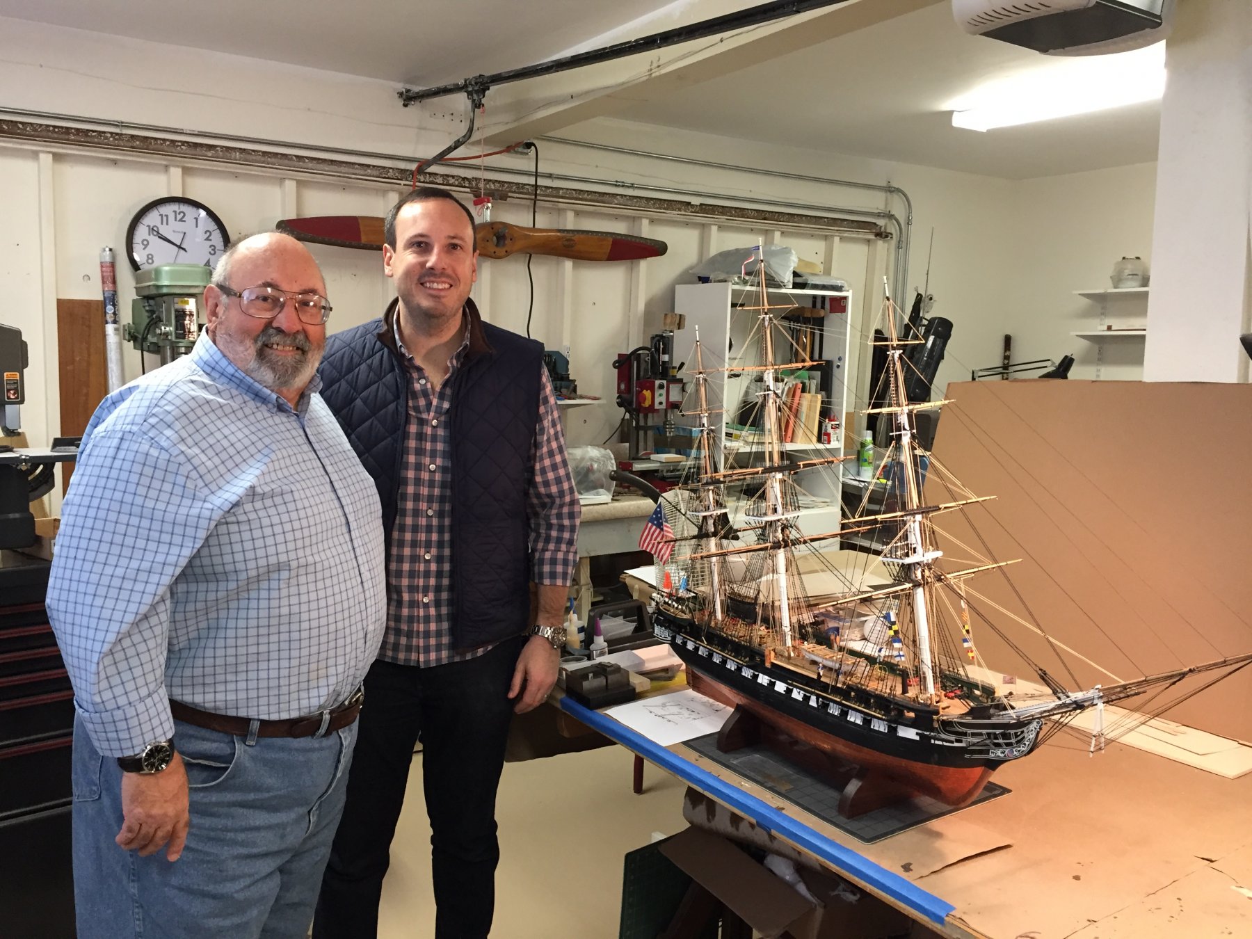
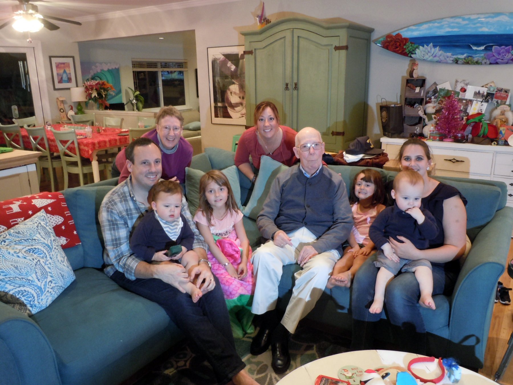
I hope all had as great a holiday season as we did with all the kids here for Christmas. We had four generations under one roof; Gretchen's father, Gretchen, our daughter Heather and Eric with grand children Sophia and Daphne; Alex and Tyler. This picture was taken at Heather's house where we spent most of the time together. Both Evan and Eric got to see their ships. Here is Evan holding his ship, still a work in progress. Here is Eric and I standing next to his. He really loved the signal flags with the boys names on them. I also spent a little time after Eric, Jamie and the boys returned to New York working on drawings for the LCVP for the Maritime Museum here in Morro Bay. At 1/12 scale it will be 36 inches long. Here is a PDF of one sheet of the plans I have so far. Once the drawings are done enough I will sort out a materials list to start the build. LCVP PLAN.pdf For now back to making the ladders and winches. HAPPY NEW YEAR to all!