Roger Pellett
-
Posts
4,519 -
Joined
-
Last visited
Content Type
Profiles
Forums
Gallery
Events
Everything posted by Roger Pellett
-
I am not particularly interested in Titanic lore but I did buy and read a copy of Titanic Ships Titanic Disasters, a serious examination of Titanic's design and sinking by a forensic naval architect and a marine engineer, John Woodward who taught marine machinery courses at the University of Michigan to budding marine engineers including this correspondent. This book is in my opinion essential reading for those interested in Titanic and large passenger vessels in general. The book is published by the Society of Naval Architects and Marine Engineers here in the US. The authors conclude that Titanic was a successful design. She was specified as a two compartment ship. The gash flooded six. She sank on an even keel and allowed her life boats to be launched (with the possible exception of the collapsible boats), and her power plant continue to function providing steam end electric lighting until the end. A couple of "improved Titanic" designs actually fared worse by capsizing before sinking. Titanic's deficiency was that she was not properly outfitted. Her owners chose not to provide sufficient lifeboats. Roger Pellett
- 2,625 replies
-
- 7
-

-
- kaiser wilhelm der grosse
- passenger steamer
- (and 1 more)
-
Canvas covered decks have been used on yachts even into relatively modern times. L. Francis Herreshoff was a proponent of these, and in the late 1940's my father built a Herreshoff designed Prudence H-22 sailboat with a canvas covered deck set in paint. Wooden Boat had an article on the subject several years ago. A few years ago there was a Herreshoff H-28 ketch here in the harbor. It had a teak deck sprung into a king plank and it looked totally out-of-place. Herreshoff would have disapproved. The modern plywood decks with synthetic fabric set in epoxy are direct descendants of these canvas covered decks. I would think that a canvas covered deck on a royal yacht would be an entirely practical moth of for protecting passengers and furnishings below, and decorating it with paints would be a plus. Roger Pellett
-
Learning something new whether a new technique or more about the vessel that you are modeling is what makes this hobby so fascinating. Roger
- 227 replies
-
- 7
-
-
- BlueJacket Shipcrafters
- Stephen Hopkins
- (and 2 more)
-
Nils, If you don't mind using plastic sheet you might consider using the model boat that you bought to vacuum form the boats. I would led recommend forming them in port and starboard halves. You would have to cut your model longitudinally in half. When the formed halves are cut from the flat sheet you have a nice little flange on each side to glue together that can then be shaped for the keel. The thwarts and air tank top can then be cut out as sa third piece and glued into the top.with your abilities, I'm sure that you would have no trouble mass producing them. If you have not used vacuum forming it is simple, and foolproof. A shop vacuum provides plenty of suction. You can produce a wonderfully light delicate boat that will look even better than the model that you bought. Roger
- 2,625 replies
-
- 5
-
-
- kaiser wilhelm der grosse
- passenger steamer
- (and 1 more)
-
Nope, the offset rudder is an intentional design feature called a contravene rudder. It is a form of contravene propeller, a term described in the SNAME glossary of maritime terms. Any water behind the propeller moving faster than the undisturbed water surrounding the ship contains kinetic energy and in addition to steering the ship this rudder's job is to maximize recovery of this kinetic energy by straightening the flow. A photo of the American Victory in dry dock shows this same rudder feature. This photo was published in the NRJ several years ago. In PN Thomas's British Tramps, Volume I general arrangement drawings of Liberty ships do not indicate this feature. In fact the Liberty's British predessor appears to have a single plate rudder. Thomas also says that a number of Liberty ship rudders failed and the rudder was redesigned late in the war. So the American Liberty's rudders were redesigned. The question is whether this feature was incorporated when the Americans revised the British design or was it added when the rudders were revised late in the war. Roger Pellett
- 227 replies
-
- 5
-
-
- BlueJacket Shipcrafters
- Stephen Hopkins
- (and 2 more)
-
Bob, The kinked rudder is an example of what naval architects call a contraguide propeller, more specifically a contraguide rudder. The swirling wash coming from a rotating propeller contains kinetic energy. With the propeller operating in open water such as with a twin screw ship this kinetic energy is lost as eventually the water slows down to match that of its surroundings. This energy is then lost. When this propeller wash is interrupted by an appendage such as the rudder of a single screw ship the flow is affected and some of this kinetic energy is transferred to the ship. In the case is of a single screw ship the rudder captures some of this energy by straightening this flow. It therefore stands to reason that if the rudder is twisted in a direction opposite to the rotation of the propeller it will be even more effective at straightening this flow and will recapture even more of this lost energy. This "twisted" rudder is therefore an energy saving device. Given the fact that Liberty ships were supposed to be simple easily built and expendable, it is surprising that they built with this feature. I wonder if the contraguide rudder on the Jeramiah O'brian was added later in her life. Since you are meticulously building a model of a very early Liberty, you might want to see hi she was built with one of these rudders. Your book with all of the design memos might tell you this. Roger Pellett
- 227 replies
-
- 6
-
-
- BlueJacket Shipcrafters
- Stephen Hopkins
- (and 2 more)
-
The difficulties of sailing this large craft with only one sail can only be imagined. There is no way to balance the rig. A high level of seamanship This ship is supposed to visit us in Duluth in August assuming that they can resolve their pilotage issue. It is hard to imagine what expertise a pilot used to piloting foreign diesel engined vessels could apply to this single sailed shallow draft vessel. Roger Pellett
-
The following is offered for what it's worth, without getting into a discussion about exactly constitutes scale. I went through a variety of materials in my stash and measured thicknesses with a set of digital calipers. Results are approximate for a number of reasons including the amount of pressure on the calipers. I tried ro keep it light. No. 10 duck canvas left over from a canoe restoration job. .032in. At 1:32 scale that I am building to, this would require a material of .001in. Unidentified tightly woven unbleached muslin type material from a fabric shop. .005in Drafting linen (or cotton) with the starch washed out. Some actually liberated from the old US Navy Bureau of Ships trash. This has a nice even weave with no "pics". .002in Oriental rice paper .001in Lightweight silk span from a 30+ year old model airplane kit. .001in. I am building a 1:32 navy longboat that I plan to display with furled sails. I will probably use drafting linen for the main sail and stay sail and rice paper for the flying jib. Roger Pellett
-
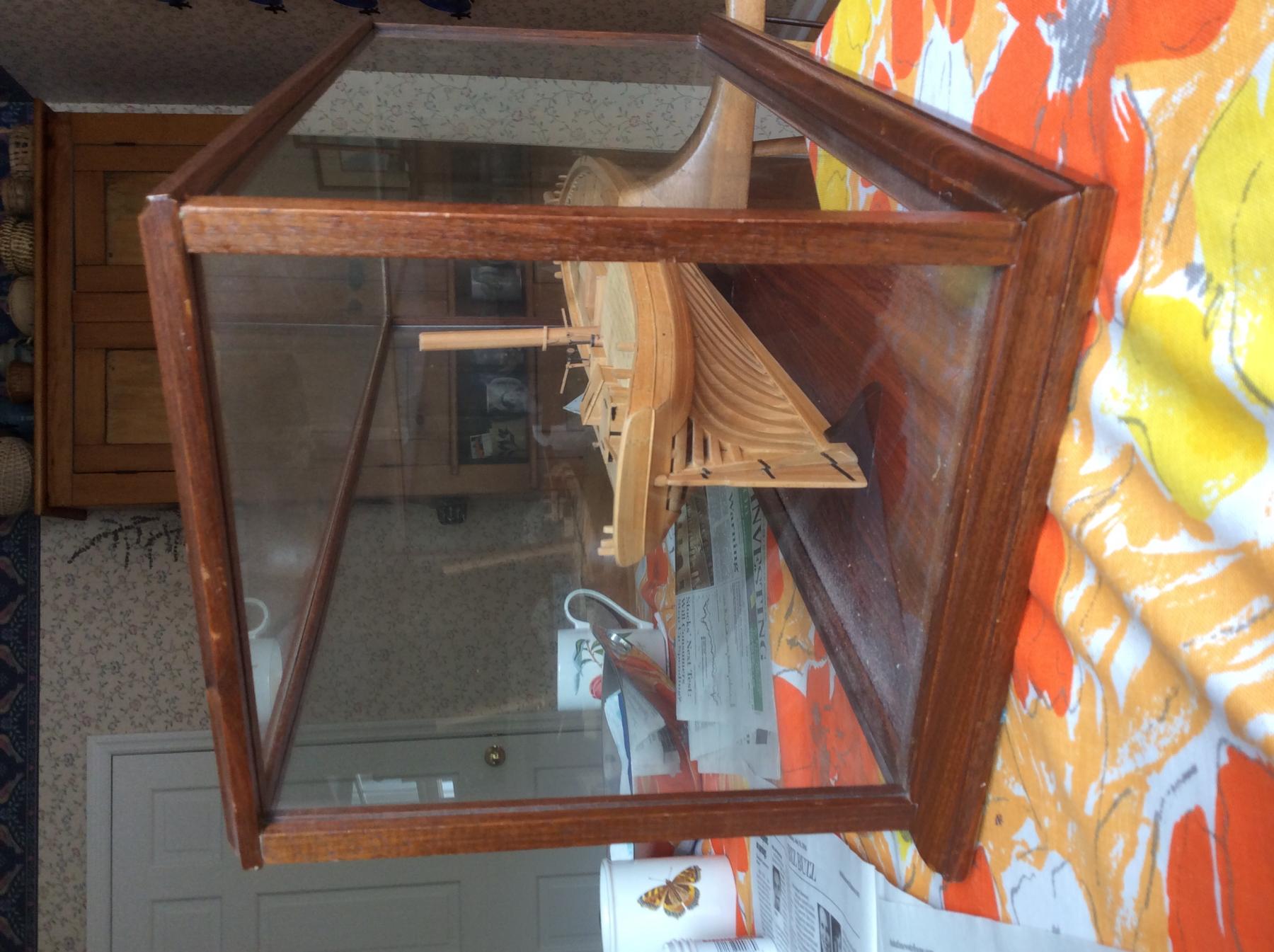
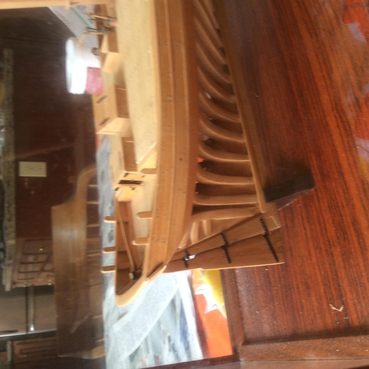
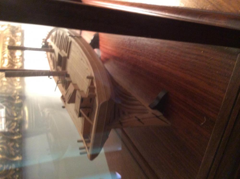
Hi Carhead, Two pictures added, hopefully better than the last. It looks like someday, I need to take the model out of the case to dust, but not today. I don't think that there is any way to build this kit to accurately represent actual practice without major surgery. Assuming that the bottom of your transom now sits on the horn timber, you need to erect angular knees on top of it. These knees will be at an oblique angle equaling the sum of the rise of the sheer line and the slope of th transom. The lower part of these knees should be cross planked and the transom will be fixed to the upper. Since this vessel has no bulwarks, the transom will appear perched up somewhat as shown in the Lousiana picture above. Roger


- 96 replies
-
- 6
-
-
- topsail schooner
- revenue cutter
- (and 3 more)
-
Hi Cathead, Sorry, taking pictures through a glass case is difficult. Tomorrow AM I'll try to get a better picture outdoors. Furthermore, my description was incorrect. The hull planking does twist up to the top of the horn timber but the transom does not sit directly on top of the horn timber. Instead, there is a series of transom knees that mortise into the top of the timber. The lower part (the more horizontal section) of the knees is cross planked and the rudder head passes through this area. The transom is fastened to the upper section of these knees. The profile of the Louisiana that you posted above shows this arrangement. This arrangement accomplishes two things. First the structure protects the rudder head. Second, it moves the main sheet aft of the rudder head. As you will recall from building your longboat, otherwise, the sheet interferes with the tiller Roger
- 96 replies
-
- 7
-
-
- topsail schooner
- revenue cutter
- (and 3 more)
-
Cathead, perhaps this might help. Planking on this type of vessel usually ran up to a horizontal cross seam at the top of the horn timber. not to the transom itself as you show. This required a major twist. Possibly, the manufacturers of the kit sought to eliminate this to simplify construction. The transom sat on top of this, the seam covered by a moulding. The attached photo shows this same construction in my model of the pilot boat Anna Maria. Roger Pellett
- 96 replies
-
- 6
-
-
- topsail schooner
- revenue cutter
- (and 3 more)
-
A variation of Kurt's color scheme for the decks that you might wish to consider would be a darker red for the decks (the paddle wheels are bright red). Red iron oxide has been used for many years here in the US as an industrial paint. It has one major virtue, it is cheap! The pigment used for this paint is iron oxide an abundant natural mineral. It has been used since Colonial times. At one time most barns in the US were painted with this paint, and here on the lakes it was and still is a favorite color for shipboard use. For many years, I worked for companies that built piping systems for industrial applications and this was used as a construction primer to protect the piping until it could be erected and insulated. When proprietary paint was costing us over $35 per gallon, this stuff cost $14 from a local paint manufacturer. I don't know what is available to you in Great Britain but here in the US this color is widely available in spray cans as a metal primer. Several years ago Eric Ronnberg published a set of color chips that included this color in the Nautical Research Journal and I believe that it has been reproduced on their website. Roger Pellett
- 225 replies
-
- 4
-
-
- chaperon
- model shipways
- (and 1 more)
-
For Beginners -- A Cautionary Tale
Roger Pellett replied to ccoyle's topic in New member Introductions
Many years ago, I had a friend who was interested in building a model ship. I suggested the Model Shipways Virginia Pilot Boat model which he purchased. As we worked together we often had lunch together and I would always ask how he was coming and offer help. His answer was always "I got it out but was afraid that I would mess it up." I suspect that upon his too early death, the kit was thrown out. My advice to beginners would therefore be a little different: Get busy and build the model before you lose interest! Your first model will not be a collector's item. You will make mistakes. Hopefully your second model will be better than your first. Today, as I build models, I still make mistakes, and as the model goes forward, I tend to remember them more than the successes, but after the model has been sitting for a while in its case in my study, I look at it and realize, wow! This is a good representation of XXXXX. This is a difficult craft and not moving ahead until you achieve perfection, will prevent you from mastering it. Roger Pellett -
Steamboats and other rivercraft - general discussion
Roger Pellett replied to Cathead's topic in Nautical/Naval History
The Winter 2007 (volume 47, no 4) edition of the Nautical Research Journal includes an article titled Research Advice, American Beam Engines by Alan D. Frazier. In addition to discussing these engines, the article includes a list of sources for further research. Go to the NRJ website to see if a copy of the article is available as a digital download. If not call the office and see if they still have this edition of the journal to sell Roger Pellett- 281 replies
-
- 5
-
-
- Steamboats
- riverboats
- (and 3 more)
-
Steamboats and other rivercraft - general discussion
Roger Pellett replied to Cathead's topic in Nautical/Naval History
Several days ago there was a discussion on a build log regarding research for the steamer Chaperone and I questioned the absence of characteristic Ohio River yawl boats on a couple of well detailed models. It turned out that photographic evidence proved me wrong, but my question generated interest and a suggestion was made to move the discussion to this site, so here goes. To me, most interesting thing about American Western Rivers steamboats was the way that innovators built these vessels to adapt to the then hostile environment that existed before the rivers were "tamed" with the current system of locks and dams. Conditions varied from very high water and swift currents to very shallow water. It was supposedly said that these boats could float on a heavy dew. In these low water conditions these boats using a system of heavy spars, tackles and their steam capstans could actually be lifted over sandbars. Overcoming these navigational hazards also required a sturdy work boat to haul heavy hawsers ashore. Secured to large trees, these lines could warp the boats ahead. For this purpose, a specialized distinctive workboat called an Ohio River Yawl Boat was developed. Howard Chapelle described these boats in his American Small Sailing Craft. These boats were wide flat bottomed skiffs with considerable keel rocker and flaring top sides. This allowed the boat to carry heavy loads in very shallow water with ample stability. Modellers wishing to include one of these boats on a steamboat model will find much information on the Internet. Googling Ohio River Yawl Boat will yield a number of interesting sites. First, there is a discussion on wooden boat.com, subheading Ohio/Mississippi River Skiff Yawl about these boats. Google books also has published Chapelle's small craft book. Both of these sources include Chapelle's drawings of representative craft. There is also an interesting article about Marietta, Ohio boatbuilder adapting this indigenous design to produce a inexpensive boat for high school age rowers. Roger Pellett- 281 replies
-
- 3
-
-
- Steamboats
- riverboats
- (and 3 more)
-
Hi Kurt, The boat in the first photo is not an Ohio River Yawl boat. It does look like some sort of round bottomed boat. The boats in the next two photos are typical Ohio River yawls- fairly wide and their top sides show considerable flair all the way back to the transom. I have no idea what the boat in the fourth photo is. It almost looks like a lumberman's bateau. Alan Bates includes a brief description of these yawl boats in his Western Rivers Steamboat Cyclopedium. I'll have to do some searching to find the information that I am looking for in the NRJ. So it appears that Chaperon had a variety of boats during her life. That's not hard to believe. Roger
- 225 replies
-
- 2
-
-
- chaperon
- model shipways
- (and 1 more)
-
As long as we are critiquing this model kit, a discrepancy appears to be the use of generic round bottom ships boats. Western Rivers steamships were outfitted with specialized flat bottom yawl boats. These boats had wide sterns and flaring topsides to allow heavy loads, particularly heavy mooring lines to be carried over the stern without capsizing. This is a distinctive feature of these vessels that the kit producers probably ignored in favor of stock fittings. The Ohio River Museum in Marietta, Ohio has one of these boats on display, but that won't do you much good in Scotland. Drawings of these boats are included in American Small Sailing Craft, pages 98 and 99 by Howard Chapelle if you can find a copy and plans have been published in the Nautical Research Journal at least once. The Ohio River Museum has a website. They are also related to the Campus Martius museum also in Marietta and it might be easier to talk or email a live person there. Roger Pellett
- 225 replies
-
- 4
-
-
- chaperon
- model shipways
- (and 1 more)
-
Nice job planking the hull! Did you have to steam planks to fit the bilge radius? Roger
- 1,208 replies
-
- 1
-
-
- great republic
- clipper
- (and 1 more)
-
Attaching a Cutter's foresail to its horse rail
Roger Pellett replied to tkay11's topic in Masting, rigging and sails
My model is based on the Admiralty drawing of a 32ft longboat reproduced on page 90 of The Boats of Men of War by W.E. May. In addition to a body plan, this drawing includes a sail plan, spar plan, and a number of rigging details. Unfortunately, it does not show the sheets for either of the headsails. The boat is what we would now call cutter rigged. It has a foresail hanked to the fore stay and a jib set flying from an unstayed bowsprit. The entire bowsprit appears rather flimsy and my interpretation is that the jib was principally intended for sailing off the wind and upwind in light air. Your picture would indicate that you are a sailor so you know that for upwind sailing the foresail on this boat would be a workhorse and its sheet would be under considerable tension. While the jib sheet could be simply led through a block hooked to a convenient spot, the fore sail would require something more substantial. If you go to the National Maritime Museum website Collections.rmg.co.uk and find the online listing for drawings and search for "longboat" item 17 is a drawing titled 31ft Longboat Circa 1801. Although this is not the same boat that I am modeling, it is roughly the same size and is fitted with a fore sheet horse. I am aware that not all longboats were built to be carried aboard warships. Some were yard craft and a number of these are also shown on this same plan listing, so it may be that this particular longboat was intended as a yard craft. As a minimum in heavy air this foresail would at least need a pair of tackles each secured to an eyebolt but barring some new undiscovered information we can only speculate. Thanks for your comment. Roger -
Can you tell us who is going to put blush the book? Roger
- 641 replies
-
- 3
-
-
- greenwich hospital
- barge
- (and 1 more)
-
Attaching a Cutter's foresail to its horse rail
Roger Pellett replied to tkay11's topic in Masting, rigging and sails
Tony, I agree, the rigging of the main sheet for your cutter is exactly as described in Steel. What I have been trying to figure out is the system used on a much smaller vessel, a 32 ft longboat. Roger -
Attaching a Cutter's foresail to its horse rail
Roger Pellett replied to tkay11's topic in Masting, rigging and sails
The practice that I am describing is described for the main sheet of a cutter on page 187 of Steel's rigging instructions. Steel says "or the pin of the block in small vessels." Unfortunately, for sloops and ship's longboats Steel just says "but (rigged) much lighter." In learning to sail a small boat, I was taught never to belay a sheet and at least one 19th century seamanship manual in my library warns officers ships' boats of the same thing. On the other hand, I don't see how large boats such as longboats could be sailed without belaying or at least snubbing fore and main sheets. So my intent when rigging my longboat is to provide a horse with extended pin block for the foresail and a cleat to snub the mainsail in the stern sheets. The foresail would therefore be self tending, but the main sheet would be shifted with each tack. I would appreciate any and all comments. Roger Pellett -
Attaching a Cutter's foresail to its horse rail
Roger Pellett replied to tkay11's topic in Masting, rigging and sails
I just noticed this post. I have been pondering this subject while working on my Royal Navy longboat model as some Admiralty drawings show a horse for the foresail. My problem with knotting the tail of the sheet to itself would be trying to untie it under tension especially when wet- a necessary thing to be able to do with any sheet in a boat under sail. Steel mentions one other idea that I like better. The block on the horse is provided with an over length sheave pin on hat serves as a belaying pin for the tail of the sheet. Roger Pellett -
If you are buying power tools and are buying unseasoned lumber you might find a small jointer more useful. A surface planer does not easily handle twisted lumber. It works best if you can put a flat surface down against the platen and the cutter head then planes the other surface parallel. If you try to plane a board with two irregular surfaces the pressure from the cutter head twists the board. By planing one side flat or better yet two sides flat and square with a jointer you can then square the board's remaining sides with a table saw or band saw. You can then rip uniform slices with a table or band saw. If you still want a planer, the jointer is needed to first flatten one surface. I have a 3in Rockwell jointer that I bought many years ago. This is a heavy all cast iron tool that is large enough to handle ship modeling wood. I would rather use it than the cheaply made handy man quality tools sold by the big box retailers today. I suspect that you can find an inexpensive one used. Roger Pellett
-
Steamboats and other rivercraft - general discussion
Roger Pellett replied to Cathead's topic in Nautical/Naval History
A number of years ago the late model builder William F. Wiseman built a model of the very small river boat Myrtle Corey. He built the model entirely from photographs using geometric projection techniques. The NRG has downloadable copies describing his techniques that can be bought for a few dollars. Look up his name on their website. Mystic Seaport bought his model collection from his estate and those of us that attended last fall's NRG conference got to see them. The photo's in the Journal do not do them justice. I remember seeing his spectacular Far West model but not Myrtle Corey. Roger Pellett- 281 replies
-
- 5
-
-
- Steamboats
- riverboats
- (and 3 more)