


Roger Pellett
-
Posts
4,519 -
Joined
-
Last visited
Content Type
Profiles
Forums
Gallery
Events
Posts posted by Roger Pellett
-
-
Put the missing oil filter next to the tool box on top of a rag. 😁
- FriedClams, mtaylor, Keith Black and 3 others
-
 6
6
-
Terminology: lines running fore and aft from points on masts to the deck or the bowsprit are called stays; eg. Fore Stay- Usually runs from the fore mast head to the head of the stem.
Lateral bending forces applied to the bowsprit are sometimes restrained by lines port and starboard running from the bowsprit tip to attachment points on either side of the bow. These would be called bowsprit guys or bowsprit shrouds.
The fore stay would be attached to the stem head. In larger boats a deadeye would be turned into the bottom end of the stay. Just like the shrouds supporting the masts this deadeye would be secured with two seizings. The lanyards would go from the holes in the deadeye to holes drilled through the stem head. The jib shaped fore sail would ride on the fore stay.
The jib, a different sail, would be set from the bowsprit. The tack of the jib would be secured to a ring around the bowsprit called a traveler that could me moved back and forth along the bowsprit. This allowed the jib to be set and retrieved without a man out on the bowsprit. It also minimized the chance that when dropping the jib it would be dumped in the water and drawn under the boat. The jib on these boats was usually set “flying,” the luff did not ride up and down on a fixed stay. There would be no standing rigging supporting the bowsprit.
The longboat and the launch that replaced it in later years were the largest (in cubic capacity) of the ship’s boat outfit. As such it was assumed that these large boats would need to be capable of making extended voyages under sail. Their rig was, therefore, relatively complicated. Your jolly boat was the smallest boat carried. As Allan says it was principally a row boat that could make short trips under sail. Whatever rigging it had would have been as simple as possible. It could have just been rigged with a single lug sail carried by a mast unsupported with shrouds or stays. If the boat also had a headsail, attaching the tack to the stem head would have eliminated the need for a bowsprit.
Roger
-
I am old enough to be shocked at the current prices of most things. I still remember the 1970 annual salary of my first civilian engineering job -$12,000. The company had contracts to build nuclear power plants and was willing to pay me a premium for my navy nuclear experience. When the local school district offered my wife a teaching job at an annual salary of $7,500, with a combined salary close to $20,000 we felt that we were making “the big bucks.” 52 years later, spending $250 for a model kit is something that I would not take lightly, to say nothing of $1000.
On the other hand, if I was to buy a model kit, whether it cost $250 or $1000, I would want it to meet certain criteria:
Is it based on solid research?
Does the construction method produce an accurately shaped hull?
Does the finished model accurately represent its historic prototype?
Are the kit materials of a quality that can be used as intended by the kit designer?
Are supplied prefabricated parts; fittings, decorations, etc generic or unique to the model being built?
If generic fittings like blocks deadeyes are included, are they correct scale and correctly shaped?
Will kit supplied materials be durable over the lifetime of the model ( assume 25-50 years)?
Is documentation well written with correct grammar, and clear to scale drawings? Supplemental information regarding historical research would be desirable.
While I have no intention of downsizing in the foreseeable future, I am beginning to realize that I might not always have the luxury of a full sized workshop. When and if I am consigned to a “Luxury Resort for Active Seniors,” a $1000 kit meeting the above criteria may well be a better buy than a $250 one that does not.
Roger
- Gregory, mtaylor, Bill Morrison and 5 others
-
8
-
-
Yes, the upper brass fixture on the stem as well as the smaller ones on each side of the bow could well be attachment points for lines from a dolphin striker. I suggest that there should be a hole on the underside of the bow where the. Dolphin striker was fixed. I would also not rule out the possibility that the.re was a bowsprit spreader helping to withstand lateral forces.
I recommend that you first make a freehand sketch of the bowsprit showing all holes and attached fittings. Then we will have a better idea of what is going on.
Roger
- Keith Black and mtaylor
-
2
-
John:
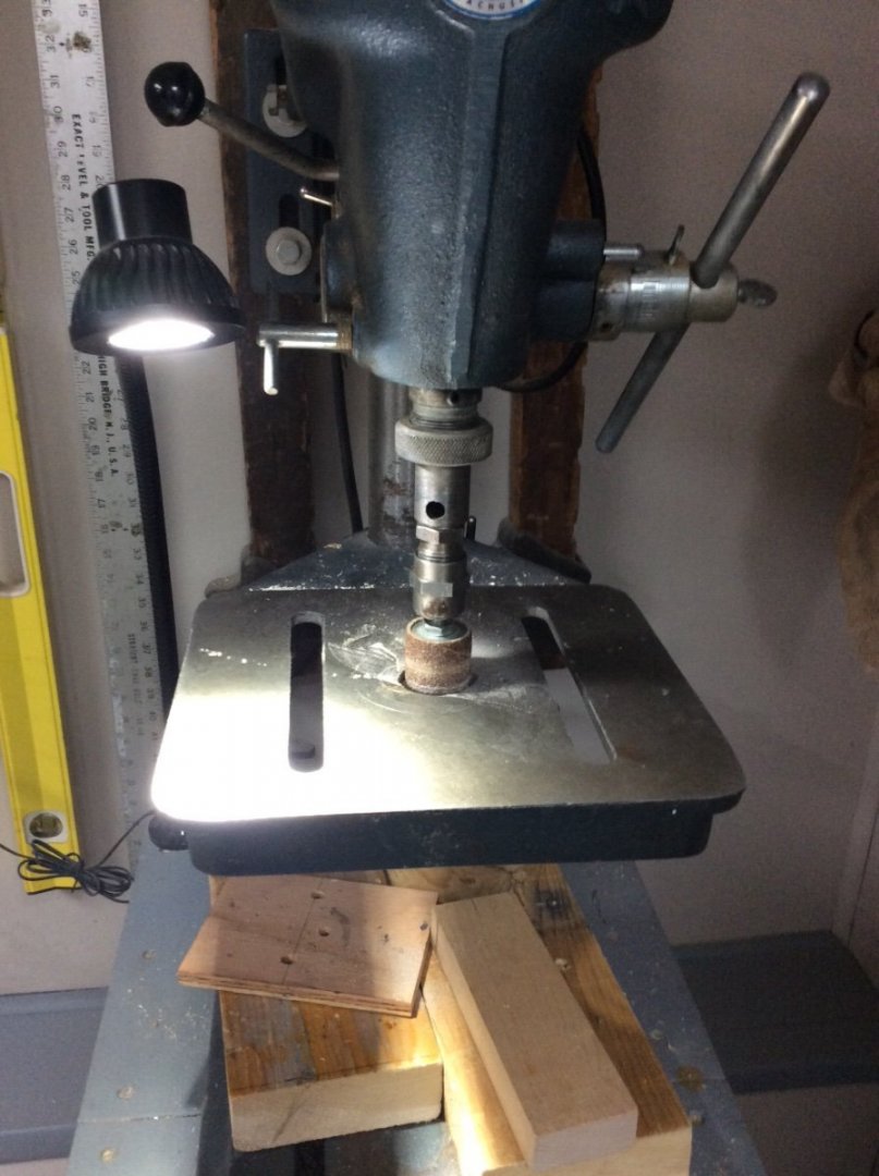
Is the lightbulb an actual lightbulb or something specially made?
- Keith Black and mtaylor
-
2
-
FDR Model’s- FDR was an enthusiastic sailor, and ship model collector throughout his life. His maritime life is covered in the book, Sailor in the White House by Robert Cross.
In 2004 my wife and I made a trip up the Hudson Valley, stopping at FDR’s Presidential Library at Hyde Park. In the entrance library there is a huge model of a Ship-Of-The-Line. According to the museum, the Queen of Holland told FDR that if he won WWII she would send him the best model that she could find. Of course FDR died before the war ended so who knows? While visiting the library, I asked a docent about the rest of his models and learned that his collection numbered about 200 models and that they were presently being restored. I later learned that the restorer is a member of our forum. His pseudonym is Shipmodel.
I revisited the library in 2019 to see his restored model collection. It is housed in utilitarian looking cabinets in the basement. Some models are quite hard to see. The models vary in quality. Many are rather simple WWII era warship models. Rigged sailing ship models are typical of those built in the 1930’s. Some models are considered significant because of their historic provenance instead of their accuracy or quality. I do not believe that his entire collection is on display.
Several models that I particularly liked, are scattered throughout other library displays; a very nice small scale model of a WWII Escort CarrIer and two models of early Higgins Landing Craft, one a LCPL.
Roger
- Canute, Harvey Golden, GrandpaPhil and 2 others
-
5
-
There are four eyes on the brass collar at the end of the bowsprit. The logical use for these would be- jib stay, Bobstay, bowsprit shrouds (2). The bobstay would attach to the lower of the two attachment points on the stem. The shrouds to the large brass points on the side of the hull.
There is a traveler on the forward .end of the staysail club (boom). The purpose of the traveler is to adjust the fore and aft position of this sale to balance the rig. A line leads forward from the end of the staysail club to a small block fixed to the aft of the two eyes at the end of the bowsprit behind the collar. This line then comes back inboard to be belayed somewhere at the inboard end of the bowsprit. The second eye on the end of the bowsprit would secure the tack of a jib.
Roger
- mtaylor and Keith Black
-
2
-
A Naval Architect would say that your model lacks initial stability. Initial stability is determined by two factors; the shape of the underwater hull and the vertical height of the center of gravity. Add more internal ballast. This will lower the center of gravity and will immerse more underwater hull. There is margin to do so as she is not floating on her “marks.”
Roger
-
I believe that the boomed staysail is not intended to replicate any actual scale appearance. Rather it is there to facilitate sailing. For free sailing, it could be set like other sails. With the double sheets the sail would not be self-tacking, but there is no also no evidence that that the boat was ever fitted with a clockwork tacking mechanism. I agree that the masts are peculiar. The short topmasts would not require spreaders.
Interesting mysteries.
Roger
- Keith Black and mtaylor
-
2
-
-
Keith,
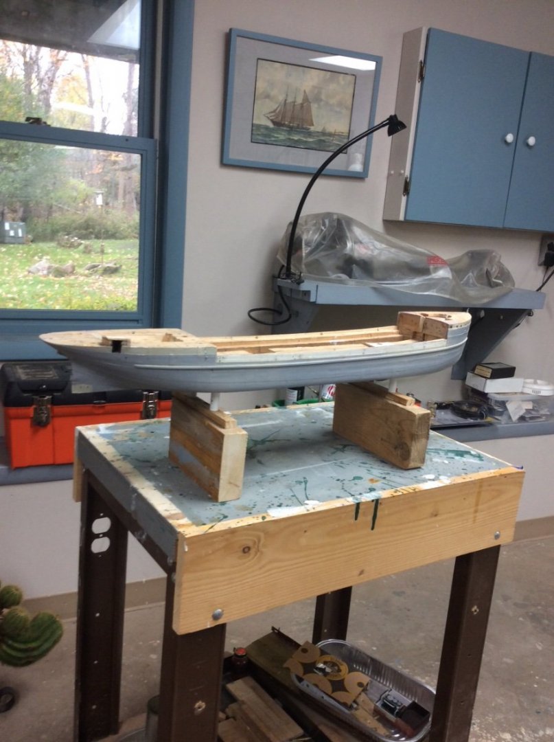
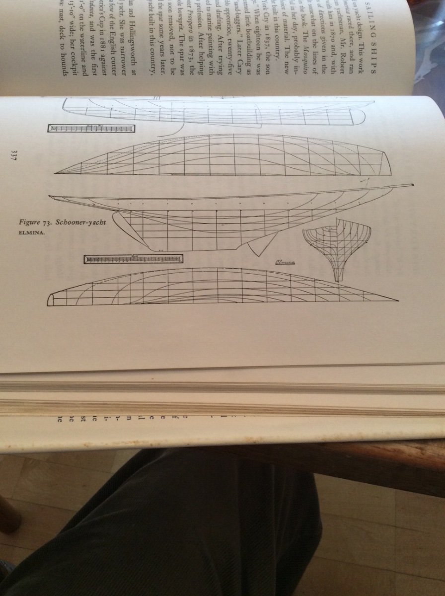
I don’t think that this is the case. If you look at Elmitra’s lines plan that I posted above, you will see that the shape of the deck of the model is completely different. Furthermore, a high class racing yacht of 1901 would not have had the two large deckhouses that exist on the model.
if this were my model, I would make a careful inventory of all parts. I would lay out a minimal rig associated with a free sailing model. If additional blocks are needed, I would try to duplicate those from the model as closely as possible. Purchased “kit” blocks will look out of place. At the large scale involved, a few new blocks should not be difficult to make. Rope- rather than worrying about scale rope I would try to duplicate to the extent possible that used to originally rig the model. He can use the jib sheets for a sample.
I would describe the restored model as a “Schooner Rigged Pond Yacht c1901.
Roger
- mtaylor, Keith Black and allanyed
-
3
-
Chapelle’s drawing of lines of Schooner Yacht Elmina. As you can see, lines are completely different from your model. I suspect that the builder of your model, who was obviously skilled, just added the name of a well known yacht of the day. This does not detract from the fact that it a nicely built model, but I personally would lean toward a simple pond yacht rig.
Roger

- Dave_E, mtaylor and Keith Black
-
3
-
I have two of these small LED lights in my shop. One over my lathe/ mill combination and one over my drill press. They are great. I found them on Amazon. Like everything else, they are Asian made. Quality seems good.
- mtaylor, Canute and keelhauled
-
3
-
Much of the answer depends on what you want to do.
If you want to rig this as a display model, there is lots of Schooner rigging information available. Your main job will be sorting out what is applicable depending on your boat’s age and place of build.
Sources that come to mind:
Howard Chapelle- American Fishing Schooners (Book) possibly not applicable to a yacht built at NY.
Drawings published by Model Shipways for New York Pilot Boat Phantom.
Eric Ronnberg’s Drawings of Boston Pilot Boat Hesper- see also his series of articles on the same subject published in the Nautical Research Journal; back articles available from NRG office.
The Gaff Rig (Book) by John Leather
Hand Reef and Steer (Book) by Tom Cunliffe.
I would be leery of using Global Schooner as a reference for small American built vessels. The author’s focus is European.
Rigging the model, in this manner, however, does not “restore” the model since as a sailing model, her rigging would have been simpler and self tending. Restoring the model to her original pond yacht configuration would be much more difficult. If you want to do this, before doing anything else I would first make a sketch showing all holes and any attached hardware. Also, take lots of photos showing her as found.
It certainly is a nice find.
Roger
-
A number of years ago there was a shop note type article in the Nautical Research Journal about modeling the engine for Admiral Nimitz’s officer’s motor boat. The article’s author was producing engine parts that included detail down to cast trademark logos. All of this was pre-3d printing and CDC machining. Unfortunately, there were no pictures of the actual model.
At the 2015 NRG Conference at Annapolis Don Pruel told me that the finished model had been donated to the Naval Academy’s collection but was not on display. If the engine is any indication of the quality of the finished model, this would be a must see.
Roger
- Keith Black, mtaylor and Canute
-
3
-
-
I last visited the Mariners Museum in 2005. At that time they had a nice collection of models on display.
- Keith Black, mtaylor and Canute
-
3
-
A fore and aft rigged boat relies on momentum to swing through the eye of the wind when tacking. Anything that interferes with this momentum causes bad things to happen; the boat gets stuck in irons or worse falls off and gets knocked down.
The proper commands for tacking a boat are Ready About followed by Helm’s Alee. Ready about notifies the crew that the helmsman intends to tack. The crew then stations themselves at their posts with whatever they need to do their jobs; winch handles, lines to be handled, etc. The command helm’s alee means the the helmsman has begun to turn the boat into the wind. Upon this command a good crew casts off and makes up lines such as jib sheets and running back stays seamlessly. An awkward job like trying to transfer a backstay across the deck is poor seamanship and risks losing the rig.
A single running backstay is not possible.
Roger
- Keith Black and mtaylor
-
2
-
This is a difficult subject: light structural members, and long thin spars and you're doing a great job.
I am wondering if these racing machines were "dry sailed" - kept out of the water when not in use. This was common back in the day of wooden dinghies to keep weight to a minimum. If so, that would account for the mast that could be lowered. On the other hand, a planked wooden boat will leak badly if allowed to dry out.
Roger
- mtaylor and FriedClams
-
2
-
Master model maker Harold Hahn developed a system for mass producing frames for POF models from two layers of solid wood. Standardized shapes were fabricated with mitered segments that followed the frame shape to avoid problems with cross grains. The joints in the two layers were staggered. Individual frames were cut from these blanks.
I have been thinking about using this system for producing POB bulkheads. Same as for POF frames except skip the step to saw out the inside of each frame shape.
What would be the advantage of such a system?
It would allow use of inexpensive and readily available lumberyard pine that could be specifically selected for quality.
It would avoid problems with plywood or MDF; warping, fastening into edge grain.
There would be no cross grain to break.
Top timbers could made from high quality modeling hardwoods selectively added to the laminated blank.
Roger
-
Chief,
The major difficulty of building a POF model is lining the frames up plumb and square in three dimensions. If this is not done accurately, your planking will not produce a fair hull. In other words you will have a lot of lumps and bumps in your planking.
Because of this, model builders usually use a system of jigs to line up the frames. There are a number of systems. Some involve building the hull right side up and some upside down. Small craft are often built upside down over a solid carved plug or a set of moulds. I suggest that before you saw out another set of frames you look through the build logs for scratch built models to find a jig system that you can adapt for your model.
Also, since you have some serious woodworking machinery, why limit your wood choices to hobby ship woods. If I were you I would visit my local Menards to see what they offer. Ours stocks a clear fine grained select pine (from New Zeeland!) that would appear to be far superior than anything from a hobby shop, and a decent sized plank will allow extra to account for mistakes.
Roger
-
Even today, there is a separation of responsibilities in building a ship. Naval Architects determine the ship’s general arrangement, hull lines, and structural design. Marine engineers select and design propulsion and auxiliary machinery.
Using this analogy in the days of sail, models were often built to show the ship’s naval architectural features, specifically general arrangement and hull shape. Once it’s propulsion System, (it’s rig) rig was defined; ship, brig, ketch, etc, no further description was necessary as riggers would use rules and customary practices.
Roger
-
Starting with a dowel is doing things the hard way. Start with a straight grained piece of flat stock and lay out the shape of your spar. Using your favorite method- plane, chisel, saw, cut the material to the correct shape with a square cross section. Now make your square cross sectioned stick eight sided, then sixteen sided. Your sixteen sided stick can now be chucked in a lathe or power drill and sanded round.


Pirat by Harvey Golden - FINISHED - c. 1920 sailing canoe from Willy Goepferich's "Der Junge Kanubauer"
in - Build logs for subjects built 1901 - Present Day
Posted · Edited by Roger Pellett
More or less related to this build log:
Many years ago I agreed to build a Folbot canoe/ kayak from a kit for a friend. His wife wouldn’t let him buy the kit because “He would not be able to build it.” I solved that problem for him.
It is my understanding that Folbots were another of the personal watercraft that originated in Germany in the early 1900’s. They were literally “folding boats” that could be carried up into the mountains aboard Germain Railroad trains, assembled and paddled downstream. They were one of the canoes with canvas covering that Wefalck mentions.
The boat that we built did not fold up and was covered with two layers of vinyl. It was a poor excuse for a boat; heavy and never paddled straight. My friend eventually gave it to me and when I moved to Duluth I traded it for a restorable wood canvas canoe.
Roger