HOLIDAY DONATION DRIVE - SUPPORT MSW - DO YOUR PART TO KEEP THIS GREAT FORUM GOING! (Only 20 donations so far - C'mon guys!)
×


Roger Pellett
-
Posts
4,519 -
Joined
-
Last visited
Content Type
Profiles
Forums
Gallery
Events
Everything posted by Roger Pellett
-
Justifying the purchase of a mill
Roger Pellett replied to Captain T's topic in Modeling tools and Workshop Equipment
Moab, By having the right tools our ability to create is only limited by our imagination. I personally know of no other human activity that provides this. Roger -
I agree with Mark. The Master Shipwrights’ Secrets is a wonderful book. It is particularly useful for anyone interested in learning the “nuts and bolts” of designing, or as they would have said in the 1600’s, modeling a Seventeenth Century ship. Roger
-
Don, If you plan to accurately model the boats for your model, I second Allen’s recommendation that you acquire a copy of The Boats of Men of War by May. Detailed information on ships boats can be hard to find and CDR May’s book is the best single reference on Royal Navy Boats that I know of. As you progress, you will find that having a good reference library available is essential. Roger
-
If this ship was specifically fitted out as a survey vessel she may well have had a special boat allowance. Serious surveying of an unknown Coast was the job of warrant officers working from small boats. These had to be seaworthy and capable of independent cruising under sail away from the mother ship. Depending on the date, the cutter and yawl might have been hung from davits. The launch being the largest, in cubic volume, and heaviest would be carried on board. Roger
-
A heads up worth exactly what you paid for it! I have no connection with the company whatsoever. Woodcraft is advertising ebony for sale, and on sale www.woodcraft.com I am aware of all sorts of toxicity problems associated with ebony and have no interest in using it myself, but if this is of interest, check it out. Roger
-
Justifying the purchase of a mill
Roger Pellett replied to Captain T's topic in Modeling tools and Workshop Equipment
Good advice is dependent on your goals: budget, workshop space and even your age (are you just getting started outfitting a workshop that you will use for many years?) First, IMHO upgrading a hand held rotary tool is throwing good money after bad. I have a 45 year old Sears “Little Crafty” rotary tool. Like most older tools made before well known brand names were slapped on outsourced products it is well made. I seldom use it, and when I do it’s for metal working. Like Bob says, it’s great equipped with an abrasive cutting disc. For serious model work it’s way too aggressive. If I were moving from “kitchen table” model building to equipping a workshop, the first major power tool that I would buy would be a drill press. Bench top drill presses are not expensive, take up little space, and compared with other power tools produce relatively little dust. They work equally well drilling wood, metals, and plastic. I use mine almost every time that I work in my shop. For drilling, with their lever operated quill they are easier to use than a mill, where the drilling column must be advanced with a handwheel If you decide to buy a drill press, make sure that it is equipped with ball or roller bearings. I prefer belt driven tools to those with electronic speed controls; better long term reliability. The Jacobs chuck on my drill press will not close on drill bits smaller than 3/32in diameter (about 2mm). I therefore, have a set of pin vices that accept smaller drill bits and can be mounted in the chuck. I believe that there is an old adage that says to buy machine tools by the pound; the heavier the better. A good drill press gets its precision by rigidity. Rigidity requires mass. My drill press is also 45 years old and works as well as it did when brand new. Roger -
Joe, Before you throttle back could you tell us what’s going on here? Is that a man overboard or is the swimmer in the water for some other reason, like trying to water ski? Instead of fighting the weather helm why doesn’t the helmsman let the boat head up until things get figured out? Roger
-
I have a friend who owns and races an Ensign on Lake Saratoga. He tells me that there is a small Thistle fleet there too. My Thistle was a wooden one that my father and I built from a kit. I owned it for 10 years. I sold it in Washington DC in 1970. A friend of mine owns a wooden Lightning and sails it in the Duluth Harbor. A University of Michigan graduate he has given it a Maize and Blue paint job. Roger
-
Joe, And Thistles too? Roger Thistle #1327
-
On a maritime history interest scale of 0-10 my wife rates about a minus 5. A number of years ago while reluctantly following me through the Chesapeake Maritime she happened on to a gallery dealing with African American watermen and seafood plant workers. It turned a boring afternoon, for her, into a memorable experience. Likewise, a 2019 visit to Mystic was enhanced by a pier side talk about the Danish lighthouse tender that ferried Jewish refugees in 1940 from Nazi occupied Copenhagen to Sweden. The boat is on permanent loan to Mystic from the New York Jewish Historic Society. Mystic was selected because they had the expertise and on-site repair yard to care for the boat. Based on several visits, it is my belief that the residents of the U.K. are much more interested in history than their American cousins. Although with my engineering background, Stepping’s structural innovations are of interest, I wonder if a never rigged warship that spent its life in ordinary will ever draw enough interest from the general public to pay the bills. Displayed and properly cared for at a major museum she would be available for examination by those interested in her engineering history. Roger
- 13 replies
-
- 6
-

-
- HMS Unicorn
- preservation
- (and 2 more)
-
There is extensive commentary about Rigging Period Ship models on precious forum posts.
-
In the 1960’s when Naval Architecture students were taught hand drafting of lines drawings, we were instructed that the bow always faced to the right. This would mean the the drawing would show the ship’s starboard side. I don’t know when this custom began. Roger
-
For a number of years after retiring I volunteered for the SS Meteor Museum. launched in 1896 and built to a unique whaleback design, Meteor is the oldest preserved ship on the Great Lakes. I can, therefore, claim a little experience with the maritime museum business. Like other countries, we have a number of historic ships scattered around the USA. Most of these, Meteor included, were acquired by civic boosters trying to promote tourism. Most of them exist on a hand to mouth existence and struggle to keep ahead of maintenance required by damage from wind and water. We also have a number of first class maritime museums that combine land based displays, preserved ships, extensive archival collections, and continuous programming. All of this encourages visitors to return often to see what’s new. Two outstanding examples of this are Mystic Seaport in Connecticut and the Chesapeake Maritime Museum in St Micheals, MD. Interestingly, both of these museums also feature working shipyards equipped to maintain the vessel’s in their collection. Mystic also has an extensive retail operation to help pay the bills. It would seem like many other features of modern life, success in the maritime museum business requires taking advantage of economies of scale. The U.K. also has two “destination” maritime museums, featuring a mix of preserved ships and shore exhibits; Portsmouth and Chatham. In reading about preservation of Unicorn, I cannot help but wonder if, painful as it would be, she would be better off as a part of the collection of one of these larger organizations.
- 13 replies
-
- 6
-
-
- HMS Unicorn
- preservation
- (and 2 more)
-
Resistance Soldering Unit
Roger Pellett replied to Roger Pellett's topic in Metal Work, Soldering and Metal Fittings
Thanks Pat, This answers two important questions. First, the American Beauty power source is AC. Second, in buying the carbon electrodes, copper plated ones are preferred. The information from those who have made their own systems says that they use carbon rods sold for air arc gouging. Roger -
Wonderful work! That ship doing the chasing had better get another reef in that mainsail and/or more canvas set on the foremast or it’s going to broach in those seas. Look at that bow wave! Hopefully those guys on the yard are adding some canvas “up front.” Roger
-
It might also be that Model Expo does not expect that anyone will pay nearly $1000 for this kit. If they were to “put it in sale” with a discount of 50% gullible buyers would still be paying more for it than they would direct from the mngr. but would think that they were getting a great deal. A number of years ago a well known department store announced an across the board price reduction, but no more sales, coupon deals, etc. This logical sales policy was a total flop. Shoppers, my wife included, missed the illusion that by waiting for sales, they were getting a great deal. Roger
-
My mother spent the last year of her life in a nursing home. When she had trouble sleeping the staff would wheel her down to the nursing station to chat. When my sister paid a visit, a staff member took her aside and said that my mother might have dementia as she was telling them stories about sailing on Lake Erie. My sister had to convince them that these stories were true. My point is that as we end our lives the world will quite quickly forget what we what we once accomplished. This includes our grandchildren, great grandchildren and so on. The ship models that we build can be a tangible link to these future generations. Several years ago, I restored a model that my father built. I made sure that his name was displayed on the nameplate in the hope that someone in the future will want to know who he was. It’s a shame that the identity of the maker of this handsome model has been lost. Roger
-
A question not addressed above is “ will the kit produce an historically accurate model?” There is no point in spending several hundred dollars to produce a model that does not look like the ship that it is supposed to represent. Many of the older European Plank on Bulkhead were notorious for producing historically inaccurate models. The models built from kits sold by the newer companies like Syren, and Vanguard, and the HMS Ontario that you were looking at are a vast improvement in this regard. If you are interested in building a War of 1812 vessel that sailed on one of the Lakes keep in mind that original drawings exist for HMS Ontario and it is my understanding they were the basis for the kit. On the other hand no drawings or design information exists for the original USS Niagara. Since the 1913 Centennial of the battle several attempts have been made to build a replica of the ship. The late Howard Chapelle, the dean of American maritime history produced a set of plans in the 1930’s and later wrote that he was not happy with them. The replica now sailing on Lake Erie was based on a new set of plans drawn in the 1980’s, and reflects US Coast Guard safety regulations and other additions required to haul passengers. While she is a handsome sailing ship no one can claim that she accurately resembles the actual 1813 vessel. I believe that if you build the current Niagara kit, you are building a model of this replica. Roger
-
Nice work, Vaddoc. Regarding the plank seams that concern you, at the large scale that you are working to why don’t you try following full sized practice and caulk them? You should be able to work thread into the seam using a miniature caulking tool made from a craft knife blade. When you paint your model the plank seams will not be hidden, just like a real wooden boat. If you don’t like the effect, you can pull out the caulking and resort to some sort of goop. Roger
-
I personally like wooden framed cases if the wooden members can be made small enough not to detract from the model. The cross section of the uprights for the cases that I make are 1/2in by 1/2in. The top framing is about 1/2in x 3/8in. Maybe use some wood more typical to Florida? Cypress and even pine come to mind. If you are thinking of a less formal look, even a particle board base imitating sand with a frameless acrylic cover. Roger
-
Resistance Soldering Unit
Roger Pellett replied to Roger Pellett's topic in Metal Work, Soldering and Metal Fittings
Ron, Thanks for your post. No apology is necessary. Intelligent discussion is the way that we learn, especially from those whose expertise is different from ours. Roger -
Joe, She would seem to be close to “all there.” And the few things missing like the wheel can be added without much research. It would appear that it will take you longer to build a display case than to restore the model. It is fortunate that she has found a home with someone capable of doing a first class restoration job. Roger
-
Resistance Soldering Unit
Roger Pellett replied to Roger Pellett's topic in Metal Work, Soldering and Metal Fittings
Thanks to all who commented. I found some internet blogs last night that I hadn’t seen before. One particularly helpful one discussed connections and cautioned that ordinary commercial electronic connectors will not work well in handling the heavy ampere loads required. You are basically designing a short circuit and the point of resistance needs to occur at the joint to be soldered, not at the connectors. I wound up buying two ground leads made by American Beauty. One I will use for the ground. The other I will use to make a handpiece. These leads have the properly tapered connectors. Roger -
Michael, Plating expansion and plate marking out are in my next post. Stay tuned ! Roger
-
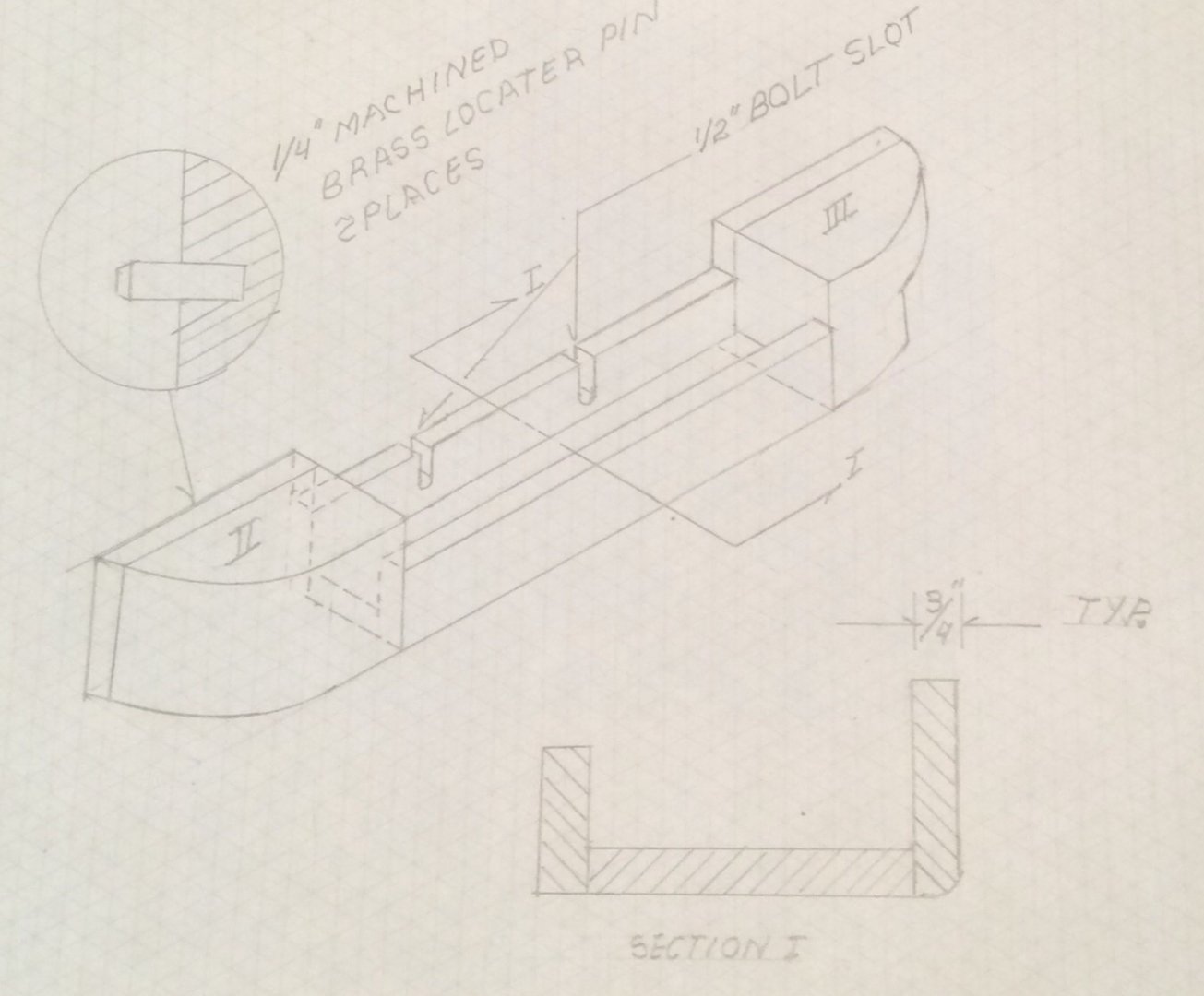
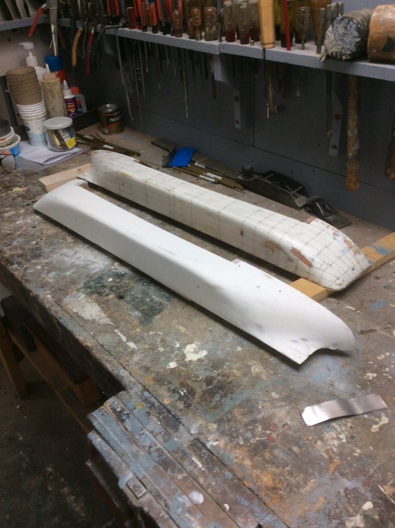
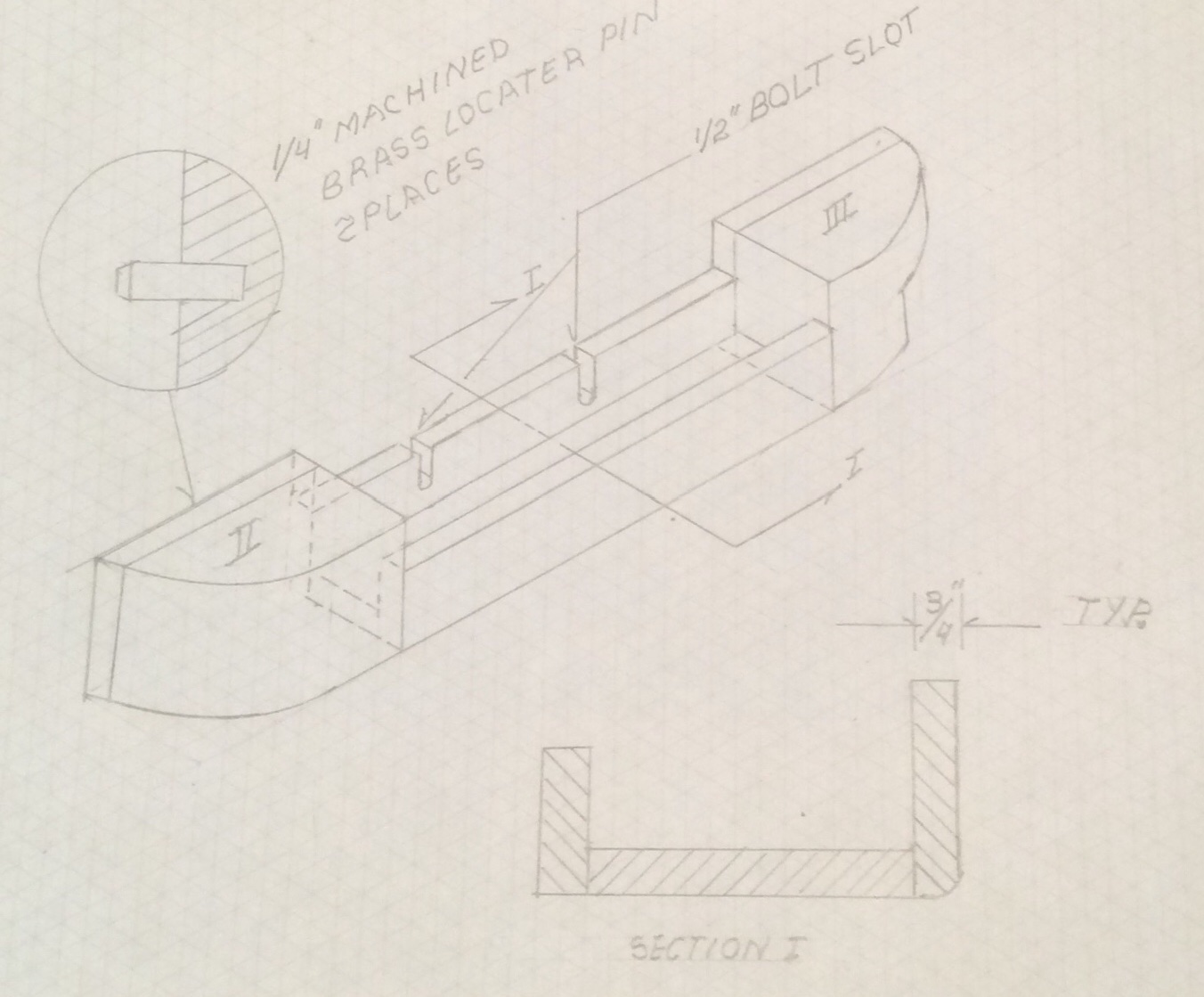
It’s way past time to catch up with my progress on this model. CHAPTER 4. Carving the Hull The basic hull for the model was built in two stages. Stage 1 in the early 1990’s and was based on my first lines drawing drawn from limited information. Stage 2 was completed after the stage 1 hull had sat for many years and was based on the lines drawn from the table of offsets. Fortunately my Stage 2 hull was just a refinement of my previous work. The hull was carved from ordinary 3/4in lumberyard pine. In doing so, I try to take advantage of flat surfaces wherever possible. I, therefore, like to make hulls as two half models. This allows the flat centerline hull surface to lay on a flat surface when checking the hull with templates. It also means that I can cut the hull’s longitudinal profile on my bandsaw. This sketch shows the scheme that I used to build the hull. It shows one half only. The holes for the locator pins for the two half hull pieces were drilled while the halves were still rough blocks. This ensures that the two half hulls will register correctly once shaped. Areas II and III are solid laminations unlike area I which was built up from three separate pieces as shown. The bilge radius along the parallel middle body was cut with a router bit. I still remember being surprised to learn in my introductory Naval Architecture course that in the real world the bilge radius was set by the diameter of the shipyard’s plate rolls. I was disappointed to learn that there was not some rigorous analysis made. Once shaped, the hull was coated with two coats of two part epoxy tank lining paint left over from a boatbuilding project. I used this because I intended to plate the hull with sheet brass secured with two sided transfer tape and wanted a smooth impervious surface. I have abandoned that idea and I hope that this coating will not interfere with the system that I choose to simulate plating. Here are the finished hull halves. My next post will discuss marking out the hull for the plating.