HOLIDAY DONATION DRIVE - SUPPORT MSW - DO YOUR PART TO KEEP THIS GREAT FORUM GOING! (Only 24 donations so far out of 49,000 members - C'mon guys!)
×


Roger Pellett
-
Posts
4,519 -
Joined
-
Last visited
Content Type
Profiles
Forums
Gallery
Events
Everything posted by Roger Pellett
-
On a whim I looked up Dockyard Carving tools on EBay and was surprised to find new tools marked “Made in USA” offered for sale. The guy selling them claims “Dockyard Carving Tools are back!” Does anybody know anything about this? Has anybody used these? Roger
-
Bob, The blades that I am describing look like but are not plywood blades. They are larger versions of the Thurston blades used with the Byrnes saw but slightly hollow ground. As far as I know, they were a proprietary Sears product. When sharp they do produce a beautiful satin finish. I met Harold Hahn on a couple of occasions, the first in 1975 at the NRG Conference held in the very small (pop 15000) Ohio River Town of Marietta, Ohio where my wife and I were living at the time. I read about the upcoming conference in our local newspaper and was surprised to learn that there was an organization devoted to maritime research and ship modeling. The attendees were a roster of whose who in the ship modeling world. I immediately joined up and this past year received my 45 year bar to go with my pin. In those days you could buy 1 inch (3/4 inch actual) thick planks of true boxwood, I still have two waiting for a project, and I believe that Hahn started with full thickness lumber to build his models. The problem with getting the blades sharpened is not the cost but getting the sharpener to not set the teeth! At least one of the blades is supposedly new. Roger
-
At present there are several Sears Craftsman “Satin Thin Rip Veneer” blades for sale on EBay. Harold Hahn used these blades to saw all of the wood for his 1:96 and 1:48 scale POF models. This was before the Preac and Byrnes miniature table saws were available. Based on his experience I bought a couple of these blades and used them to saw boxwood and pear for a POF model that I built. They worked fine. I don’t understand the need for a tilting arbor or tilting table if the saw is to be limited to model shipbuilding. 90 percent of the sawing that I do is ripping and the rest crosscutting.
-
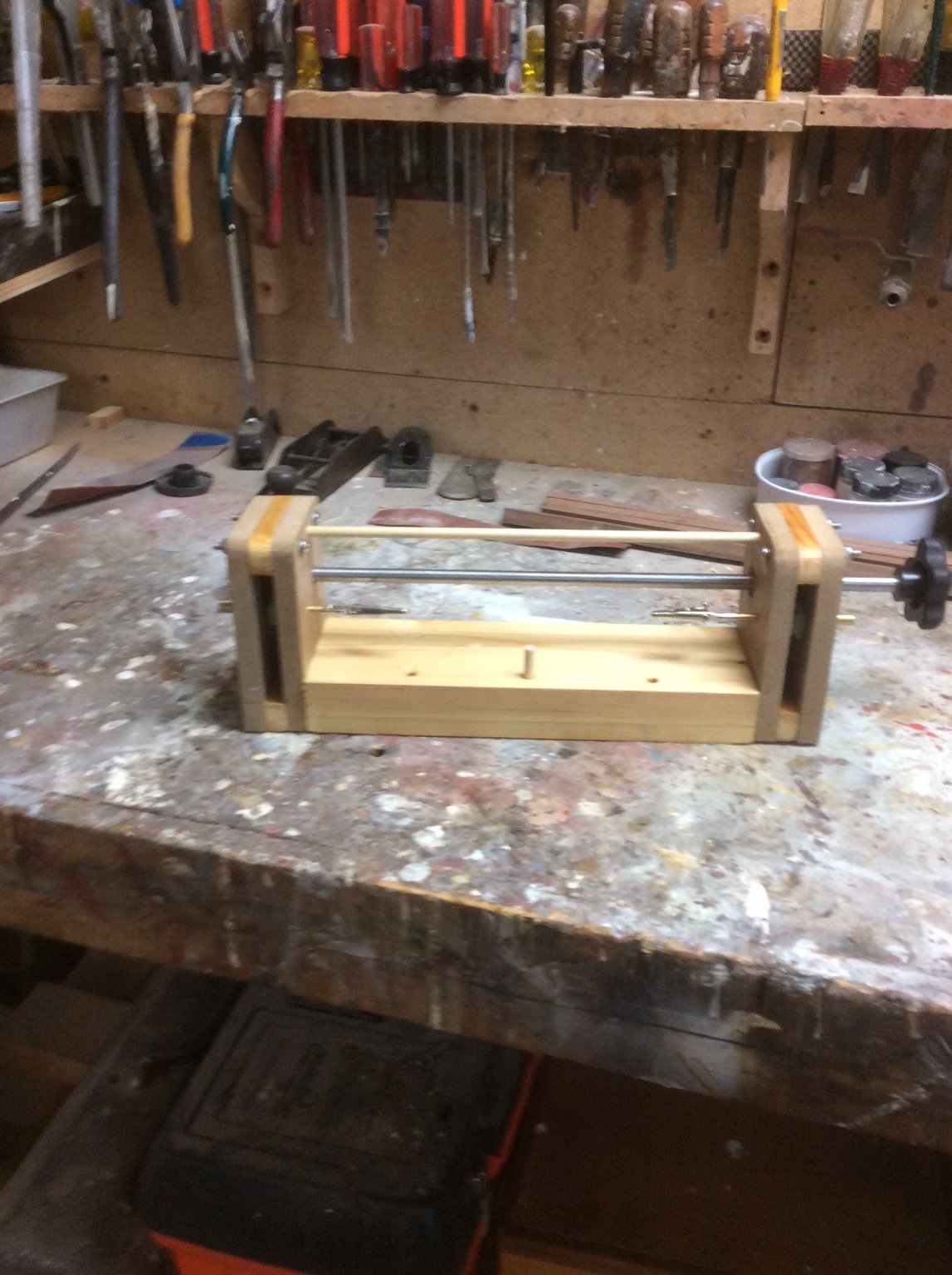
Here’s an example of a serving machine that I built several years ago. The gears are invisible as they are sandwiched between the two MDF end pieces on each side. I used gears picked up as samples at a trade scow many years ago but whole bags of plastic gears are available cheaply on Amazon. I played with a way to hold the thread spool but when I actually used it I found that it worked better just to hold it in my hand. The only things that I had to buy were the two alligator clips so the whole project cost less than $3.00 US. Roger

-
Roter Löwe 1597 by Ondras71
Roger Pellett replied to Ondras71's topic in - Build logs for subjects built 1501 - 1750
Anyone who has ever attempted to untie a knot in a wet rope under load will appreciate the brilliance of the belaying pin. This simple invention allows the hitch securing the line to be released while the rest of the line remains under tension. The belaying pin pin also solves the problem of securing the bight of the line. Tying knots usually requires the end. So, how did seamen secure lines prior to the invention of the belaying pin. I realize that ancient ships had stag horns for this purpose., but it would seem that space would not permit the dozens of these required to secure the lines leading to the deck for a complicated rig. Thoughts? Roger -
Cant frame R+S
Roger Pellett replied to Don Case's topic in Building, Framing, Planking and plating a ships hull and deck
Charles Davis got his experience working as a draftsman in the WW I shipyards building wooden ships for the Emergency Shipbuilding Program. In 1917 American shipyards built large wooden ships with regularly spaced sistered frames (two layers of timber with segments butted together and joints staggered). This reflected how large wooden Schooners had been recently built. When he got interested in ship model building he published The Built Up Ship Model purporting to be a guide to building the Revolutionary War brig Lexington “using methods just like those for building real ships”. Never mind that the plans that he provided are for a brig built for the Royal Navy years after Lexington sailed, and Revolutionary War era shipbuilding practices were not the same as those used in 1917. His book was apparently widely read and Harold Hahn used Davis’ regularly spaced double sistered frames when he built his beautiful colonial shipyard diorama in the mid 1970’s. He adapted Davis’ writings to include his “upside down” method as a means to ensure proper alignment of frames. His method per se does not prevent varying framing to more closely represent actual practice. In fact, for his model of the 74 Alfred he included two different sided frame dimensions - heavy bents, and thinner fillers in between. I personally like Hahn’s upside down method, as it provides a foolproof system for accurately aligning frames. Roger -
According to the NRJ index, the model that I remembered was of Pauline and the article was in Issue-39, pages 215- 223. Roger
-
Nice work Ian. These steel hulled sailing ships make handsome models. If I can make a suggestion, I don’t believe that any seaman would leave the bars in the capstan when not being used.
-
A bit of SLO MO SHUN IV trivia. The driver when she broke the 100mph speed record was a guy named Lou Fageol. Originally from California, by the 1950’s he was president of Twin Coach Motor Company that manufactured buses. Twin Coach was located in Kent, Ohio and he lived in a village nearby where I grew up. He lived in a beautiful house just across the street from the swimming beach on a small lake. An architectural feature of the house was a faux thatched roof built up with layers of wood. Ironically, village rules prohibited motorized boats on the lake. I don’t think that I ever met him and if I did I don’t remember. What I do remember is that one day while I was at the beach swimming his house caught on fire. My buddies and I had ring side seats as the wooden roof and the entire second story went up in flames. The house was rebuilt, wooden roof and all and when I last visited the village in 2007 it looked just like I remembered. Roger
- 55 replies
-
- 2
-

-
- hydroplane
- Slo-mo-shun IV
- (and 1 more)
-
Very nice!
-
Michael, Rob Napier built a model of a Gill Smith catboat and published an article about it 20? or so years ago. Roger
-
Help with drawings of rigging
Roger Pellett replied to DaveBaxt's topic in Masting, rigging and sails
“I’m beginning to think that the Amati drawings are a waste of time.” Dave, Exactly, that’s what I was implying in my post #6 above without being overly negative concerning kit suppliers. Amati really has no better information than is available to you from published sources since original detailed rigging plans specifically for Bounty would not have been available to them or to anyone else. The best that you can do is to follow standard practice and to make sure that nothing that you have done violates the physics of simple machines. Also keep in mind that Peterson based his book on models on exhibit in museums. As ship models age, are moved from place to place, are cleaned, etc. and the rigging is easily damaged. Also, many old models were not rigged in the first place. In these cases rigging was repaired or added by “experts.” Rigging on old models may, therefore, be as reliable a source as it might seem. The museum at the US Naval Academy has been intensively studying its collection of British Admiralty models accumulated by Colonel Rogers in the 1020’s. Before placing many of these models in his collection, Rogers had them restored by highly skilled American model makers. The result, published in a series of SeaWatch books is a case study of things are not always what they seem. Roger -
I doubt if Bob has much control over how his books are shipped. I suspect that he provides whoever warehouses his books with the buyers shipping information and they take it from there. Roger
-
Help with drawings of rigging
Roger Pellett replied to DaveBaxt's topic in Masting, rigging and sails
Dave, As none of us were around when Bounty was in existence (the original one) it is reasonable to ask where the kit designer got his information. As the three masted ship rig was common in the Eighteenth century, rigging became standardized, especially among ships of the same nationality. This was desirable as sailors joining a new ship did not have to “learn the ropes.” Therefore, any reliable source that describes standard Eighteenth century rigging practice for an English three masted ship is probably as reliable as your modeling plans. The standard work is The Masting and Rigging of English Ships of War by James Lees. It is also helpful to know how the rigging worked. If you understand the basic physics of block and tackle, you can spot and correct mistakes on your mode.ling plans. Roger -
Beautiful work Dan. This restoration requires creative solutions to problems not encountered by those of us doing “new construction.” Well done. Roger
- 95 replies
-
- 5
-
-
- POW
- Bone model
- (and 2 more)
-
Joe, My bad habit, relative to ship modeling, is reading. Like many others on this forum I love reading about history. The problem is that while reading a book. I want to dash out and build a ship model of that era. Since I can read books much faster than I can build models I sometimes find it hard to focus. Roger
-
I am fortunate to have several sizes of “Cuttyhunk” hard twisted linen line. I used it to rig my 1:32 scale longboat model. I first made a table of all lines, standing and running on the boat and the diameter of each line required. Where necessary I converted from circumference. I then measured the sizes that I had available using the system of counting the number of turns wrapped around a known distance on a dowel and matched these up with required sizes as closely as possible. It’s better to rig with lines slightly smaller than too large. Where necessary for smaller sizes I filled in with cotton thread and fly tying line. In his wonderful book about restoring the model of the Dutch ship Valkenisse Rob Napier includes a discussion about dying linen rigging line. After considerable research he decided to use Pro Chemical fiber reactive cold water dyes. The book includes instructions and formulas. I bought the necessary colors from Pro Chemical plus the necessary fixative. I followed his instructions, or at least I thought so, and wound up with white thread! At that point I said. @#$&* I need to finish this model and pulled out my trusty bottle of Feibeig dark brown leather dye plus some dark maple wood dye. I used these for standing and running rigging. Color could be adjusted by varying exposure time to the dye and the aggressiveness of wiping down the line after dying the. I was quite pleased with the results. If the dye eats the line I’ll either re-rig the model, or will be to the point where I’m unable to care. I still have my jars of Pro Chemical dyes. I will see if I can get them to work on my next model. Roger
-
After blackening, I spray mine with a light coat of Dulcote.
-
Gee Bob, I don't know. I think that I prefer the $699 pencil making kit. 😆
-
I don’t know if it’s available in the UK but one of my essential modeling tools is a bar of. Lava Soap that I keep next to my wife’s laundry tubs. I also keep a pump bottle of industrial hand cleaner in my shop. I have tried disposable gloves but I find that it’s easier to just clean the paint off my hands.
-
Yes, I just filed straight across with both the stone and the file. It seemed to work. While cleaning and sharpening the blade was necessary. I am convinced that even a slight bit of fence misalignment affects the saw’s performance.
-
Thanks for posting this Bob. I met her at a NRG Conference back in the 1980’s. Either Newport News, or Alexandria, VA. Just a passing hello. As I said, I remember her as a well known and published ship modeler back in the day but that’s all. I am fairly sure, however, that the wrote something on Fubbs.
-
I am posting this to tell forum members about reconditioning my Byrnes saw. In doing so I hope to help others wanting to improve the performance of this precision machine. I don’t remember exactly when I bought my Byrnes table saw but I would not be surprised if it was 20 years ago. I must admit that it has not been an entirely happy marriage; burnt blades, stalling during cutting, kickbacks, etc. So before tackling a new ship model project, I decided to see if I could improve its performance to the point where I could use it without getting frustrated. I first gave the saw a good cleaning and a needed oiling of the blade adjustment mechanism. I then made a simple bracket from aluminum angle that mounted via a #4 machine screw onto the slide of my miter gage. My dial indicator could then ride back and forth along this slide to measure the parallax of the rip fence. I found that the rip fence from the front of the saw to the approximate centerline of the blade spindle deviated from parallel by .006in. To correct this I followed Jim’s procedure posted above. All went well until I got to the last step. Each time I loosened the front and back brass finger screws, slid the fence back and forth and retightened the brass finger screws (front first) the fence measured.006in out of parallel. It finally dawned on me that tightening the back finger screw was pulling the fence out of alignment. I then went through the alignment procedure except loosening the two #4 cap screws mounting the back mounting bracket to the fence instead the four #4 cap screws on the front bracket. This solved the problem as the fence when slid and locked into place remained parallel. I then tackled the blades. Inventory revealed several Thurston I-192 and I-193 blades, all discolored with deposits of resin. I began by scraping this off with a single edged razor blade, and cleaning with a Dremel rotary wire brush. I later tried my wife’s fabric pre -treatment spray. This loosened the deposit to where it was removed easily. The blade teeth seemed sharp but were badly discolored. A block of wood with a piece of 1/2in dowel made an effective fixture for holding the blade. Each tooth was addressed with a small triangular sharpening stone followed with a triangular needle file. As a final measure, a piece of abrasive cord was run through the gullet of each tooth. Like dental floss! I was surprised at the amount of black “gunk” that was removed. Today I mounted a resharpened I-193 blade in my saw. Using a block of wood to push a piece of 1/4in thick hard maple against the fence and using a push stick I easily sawed off two strips. There was no discoloring or fouling of the blade. I cannot remember when the saw has worked this well. Similar measurements on my10in table saw indicate that it’s fence is out of alignment by as much as .03in, five times that of the Byrnes saw, but its enormous power allows it to effortlessly chew through almost anything. The lower powered Byrnes saw and metal slitting blades requires much closer alignment. In the future I will check it regularly.
-
The late highly skilled ship modeler Portia Trajkesman built a model of Fubbs and wrote something about it, maybe an AOTS book. I probably butchered the spelling of her last name and wish that I could be more specific. Maybe other old timers will remember better. Roger
-
The Romano book on building Fubbs is (or has been) on sale on eBay for $185. Like a lot of stuff on eBay there is no explanation of what’s included; drawings? You’re just expected to pay your money and see what shows up.