HOLIDAY DONATION DRIVE - SUPPORT MSW - DO YOUR PART TO KEEP THIS GREAT FORUM GOING! (Only 68 donations so far out of 49,000 members - Can we at least get 100? C'mon guys!)
×


Roger Pellett
-
Posts
4,519 -
Joined
-
Last visited
Content Type
Profiles
Forums
Gallery
Events
Everything posted by Roger Pellett
-
0.016 iron rod
Roger Pellett replied to Tom in NC's topic in Metal Work, Soldering and Metal Fittings
Tom, By specifying “iron rod” the kits instructions are trying to tell you not to leave these as shiny brass as seen on so many otherwise nicely done kits. They should be blackened to look like iron. You will have to touch up solder with flat black paint. Roger -
Some of the dispersed fire tactics of the British Army can be traced back to experience gained in North America during the French and Indian was, the Seven Years War in the UK and Europe. After Braddock’s defeat at the Monongahela, several officers began to consider tactics that would work better in a wilderness environment. One of these was Lord Howe the older brother of the two Howes who fought in the American Revolution. He was sadly killed at the battle at Fort Ticonderoga. The most famous of the new units formed as a result of this was Rogers Rangers made famous by Spencer Tracy in the movie Northwest Passage. While the Rangers were useful as scouts and long range raiders they were not intended to fight alongside troops in formal battles. A less well known unit that did pioneer dispersed fire tactics in a battlefield environment was the 60th American, later the 60th Royal American. This was recruited from American Volunteers and Commanded by a Swiss Immigrant named Henry Bouquet. If my memory is correct they later became part of the Rifle Regiment. Roger
-
There was also the siege at Vicksburg that ended with the Union Army capturing the city on the same day that the Battle of Gettysburg ended. Roger
-
Druxey, Your oar is beautiful! If I may offer a suggestion, I would gently round the tips. We don’t want the crewman catching a crab in choppy water. Roger
- 433 replies
-
- 6
-

-
- open boat
- small boat
- (and 1 more)
-
One thing that scratch building does require that kit building does not is a plan for building the model. In my case this includes both how I am going to build it and in what sequence. These are challenges that I enjoy. Roger
- 433 replies
-
- 5
-
-
- open boat
- small boat
- (and 1 more)
-
Keith, Civil War era navies seem to have made wide use of this “Jackass” rig. I don’t know what else to call it. With that in mind, you might want to get ahold of the series of articles published in the Journal, I think in the ‘90s describing the research involved in building a model of USS Kearsarge. You should be able to track them down on the Guild’s website. While your ship is larger, the rigs appear to be similar. Roger
-
OC, There have been thousands of books published about the ACW and many movies. In my opinion, by far the most accurate movie is Gettysburg. If you have access to it, it is well worth your time to watch it. ,The music score is great too. Roger
-
Exactly what landing craft are you building? American? British? And designation (LCX)? Roger
-
Ken, I too am interested in Civil War Cavalry operations because my great grandfather James H. Speer served in the 7th Ohio Cavalry from September 1862 when the regiment was formed until he was discharged as disabled in January 1865. The Unit was nicknamed “The River Regiment” as the men came from the Southern Ohio counties bordering the Ohio River. The regiment fought exclusively in the Western Theatre. A detachment from the 7th Ohio captured Morgan and his men when they raided Southern Ohio. Later it served in the siege of Atlanta. In December 1864 it fought in the campaign to turn back Hood’s invasion of Western Tennessee. Dismounted, they were part of the Union right flank assigned to turn Hood’s left, and mounted pursued Hood’s defeated columns after the battle. As he was discharged with a disability approximately a month after the battle, I have wondered if he was wounded. He died in 1893 and is buried at the Ohio Soldiers and Sailors Home in Sandusky, Ohio. Roger
-
Bow & Stern blocks
Roger Pellett replied to DaveBaxt's topic in Building, Framing, Planking and plating a ships hull and deck
Here in the US lumberyards and Home Improvement stores sell dimensioned construction lumber described as SPF which stands for Spruce, Pine, Fir. The store where I shop also has 5 quarter pine (1-1/2 in) that believe it or not comes from New Zeeland. There are several varieties of pine but the stuff sold by these stores as planed boards works fine for carving hulls so would work for the blocks that you need. It is easy to carve but harder than basswood. Unfortunately I don’t know what is available in Great Britain. Roger -
There were a number of battles in American History that began as Meeting Engagements where one or both sides did not have time to scope out the terrain; Braddock at the Monongahela, Lee and Washington at Monmouth, Grant in the Wilderness, Lee at Gettysburg. In many of these cases a lack of maps and difficulty of American wilderness terrain was a contributing factor. Contrast with European experience. During the Blenheim Campaign, military engineers on both sides were assigned the task of surveying the terrain to decide where battles could be fought to advantage. Roger
-
Allen, The Book is Fatal Sunday by Mark Lender and Garry Stone. There are are plenty of other battles where “someone didn’t get the word. I also recently read an account of the Battle of Blenheim. At one point in the battle the English commander John Churchill was badly pressed by the French and requested help from a neighboring Imperial unit. It’s Commander refused because he had no orders from Prince Eugene, the commander of his wing. Valuable time was wasted trying to find the Prince who was leading an attack over broken ground on the other side of the battlefield. Roger
-
I’d bandsaw it into 1in thick planks in whatever lengths you find to be convenient, and stack it up indoors. Put spacers between each board and it’s neighbor in the stack to let air circulate. I would saw it into ship model sized pieces on an as needed basis. Roger
-
I recently read an excellent account of the American Revolutionary War battle of Monmouth Court House. This was a complicated battle fought over difficult terrain with overall command the responsibility of two Generals; first Charles Lee and later George Washington. The author does an excellent job of illustrating the difficulty that the generals had delivering orders to unit commanders as aides could often not find them. Unit flags could be used to mark the location of the Unit Commanders. By the Civil War, the Union Army had a system of unit commander flags specifically used to mark his location. In modern jargon these flags were early command and control devices. Roger
-
Craig, I have no experience doing what you want to do. Your first problem would seem to be finding an adhesive that will stick to both the fiberglass hull and the planking. Epoxy comes to mind, but it’s slippery, messy stuff and trying to secure planks on curved surfaces would seem to be a problem. Wooden ships built on the Lakes during the second half of the Nineteenth Century would have been built to rules published by the Society of Lake Underwriters. I have not seen these documents but they should provide rules for planking. You are fortunate living in Green Bay to be within easy traveling distance to museums in either Sturgeon Bay or Manitowoc. If they don’t have a copy, see if the University of Wisconsin Green Bay can find one within their system. The Jim Dan Hill Library at UW Superior has a large collection of Great Lakes Shipping documents. Roger
-
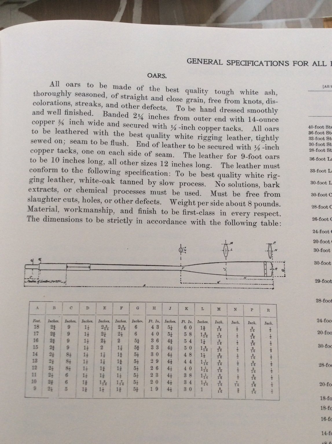
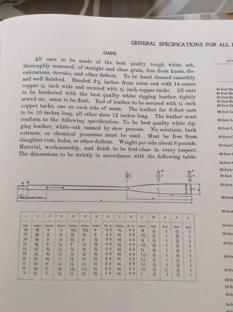
The following information is from “ Standard Designs For Boats of The United States Navy” by Philip Hitchborn, U.S.N. AKA “The U.S. Navy 1900 Boat Book. Although published 45 years after your model other than development of ironclads and steam propulsion, the U.S. Navy was very resistant to change in the second half of the Nineteenth Century. The Book lists a 28ft Cutter. With breadth of 7ft-5in and depth of 2ft-8in. The boat could be steered either with a short tiller passing through a mortise in the rudder head or a yoke secured by a tenyon atop the rudder head. The boat was rowed double banked with 10 oars; 8, 14’-0” Long and two 13’-0” Long. Position of the leather was 2’-7” and 2’-4” respectively.
- 433 replies
-
- 10
-
-

-
- open boat
- small boat
- (and 1 more)
-
Just signed up. Roger
-
It looks like a Spitfiresky!
-
Sherline Mill Essential Accessories?
Roger Pellett replied to Some Idea's topic in Modeling tools and Workshop Equipment
Since you’re already paying shipping from California to the UK, I would suggest extra T Nuts and 1 or 2 of the socket head set screws with the point on the end although your mill might not use them. My milling column does and one broke. I recently bought a slitting saw arbor for a non ship model use but can think of several ship modeling uses. I second Wefalck’ recommendation for a milling vice. Roger -
Windfilled sails with silk span
Roger Pellett replied to Markus16's topic in Masting, rigging and sails
Many years ago the original Model Shipways, the Yellow Box Era, sold a light very tightly woven fabric called Balloon Cloth for sails. I made some sails from it using Markus’s glued panel method. The sails turned out well. I recently tried to find some on the internet but could only find ads for balloons. No longer made? Roger -
Very nice work, Re: Paper sails. Two years ago I completed a scratch built Royal Navy Longboat with rigged silkspan sails and rice paper flags. As you say, both of these are delicate easily damaged materials. I made a simple “picture frame” and taped the paper or silkspan to it. I then lightly sprayed it with water and it dried drum tight. It could then be sprayed with thinned acrylic paint. The sails and flags were cut from the prepainted material. I am currently using paper to simulate plating on a steel hulled ship. Before cutting the plates I have been spraying the paper with shellac from a spray can. It makes the paper much more durable and doesn’t seem to have any effect on subsequent painting. There are a couple of areas where the plating curves in two directions, like a sail. I found that I can wet the untreated paper and form it over the curved area of the hull. When dry, I then spray it with shellac. Roger
- 179 replies
-
- 3
-
-
- longship
- Helga Holm
- (and 1 more)
-
Pat, I agree 100%. Writing and getting my book about whaleback ships published was my first introduction to copyright procedures. Fortunately I had the expert help of a retired librarian . The book itself is copyrighted and if anyone wants to own it they have to buy a copy. The majority of illustrations in the book though are in the public domain so anyone should be able to use them. We were, however, advised to get permission to publish them from the library that held them in their collection. Very confusing. Roger
-
For a delicate model like this, I that slender simple brass rods wood look good. Roger
- 433 replies
-
- 4
-
-
- open boat
- small boat
- (and 1 more)
-
Yes but, If a private company is doing and paying for the excavation and studying I agree the information belongs to them. On the other hand, projects of this type are often done by Universities and other “non profit” entities that rely on grants. These grants often come directly or indirectly from from State and Federal Governments. In these cases the public has already paid for the information. For example, Texas A&M University’s Nautical Archeology Department publishes high end and expensive books for those who want to buy them but also makes much of their research available free in digital form. Roger Pellett