


hdrinker
-
Posts
170 -
Joined
-
Last visited
Content Type
Profiles
Forums
Gallery
Events
Posts posted by hdrinker
-
-
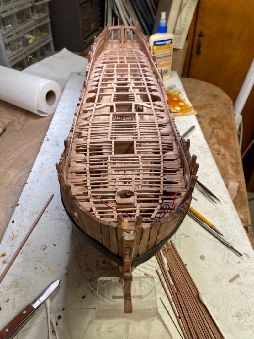
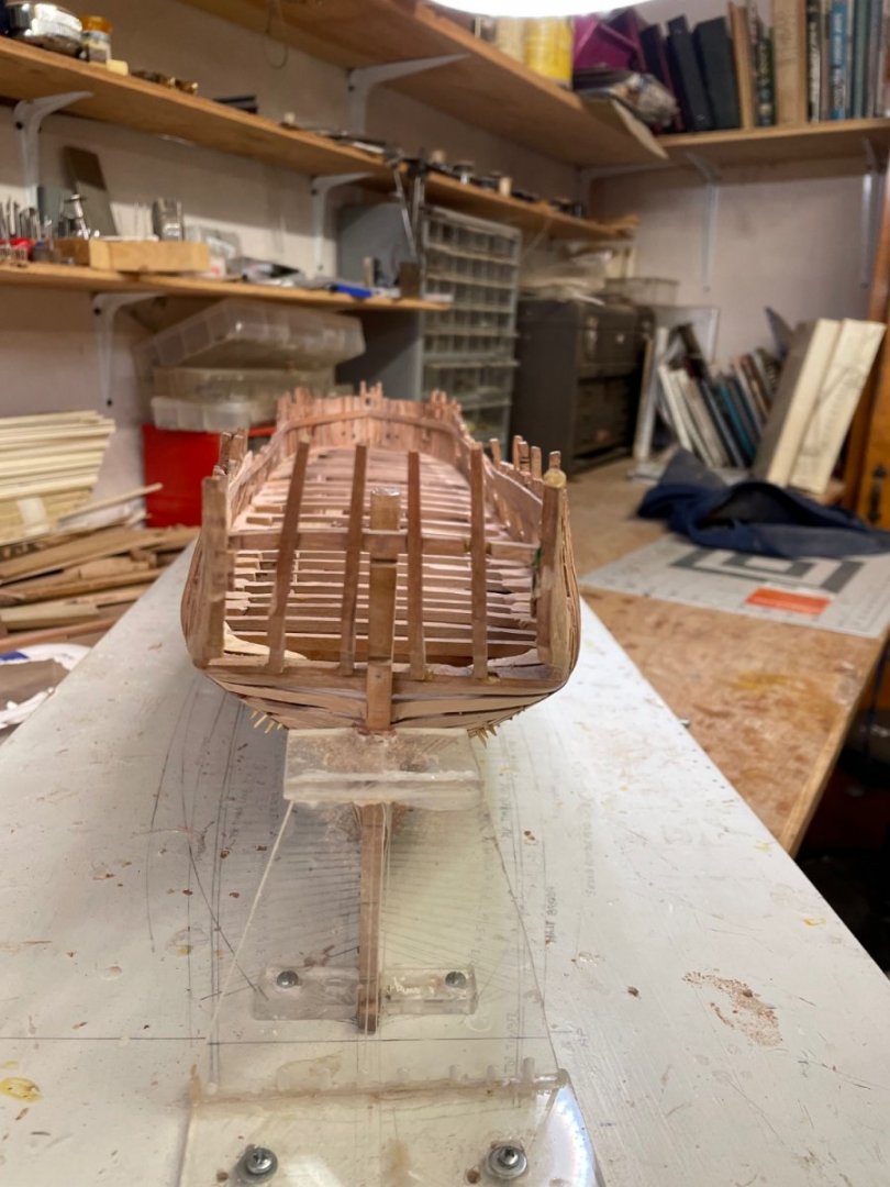
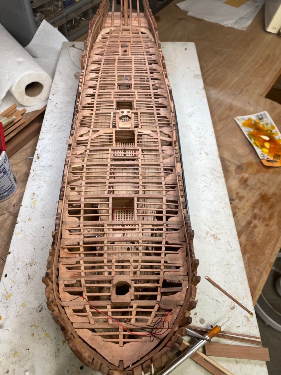
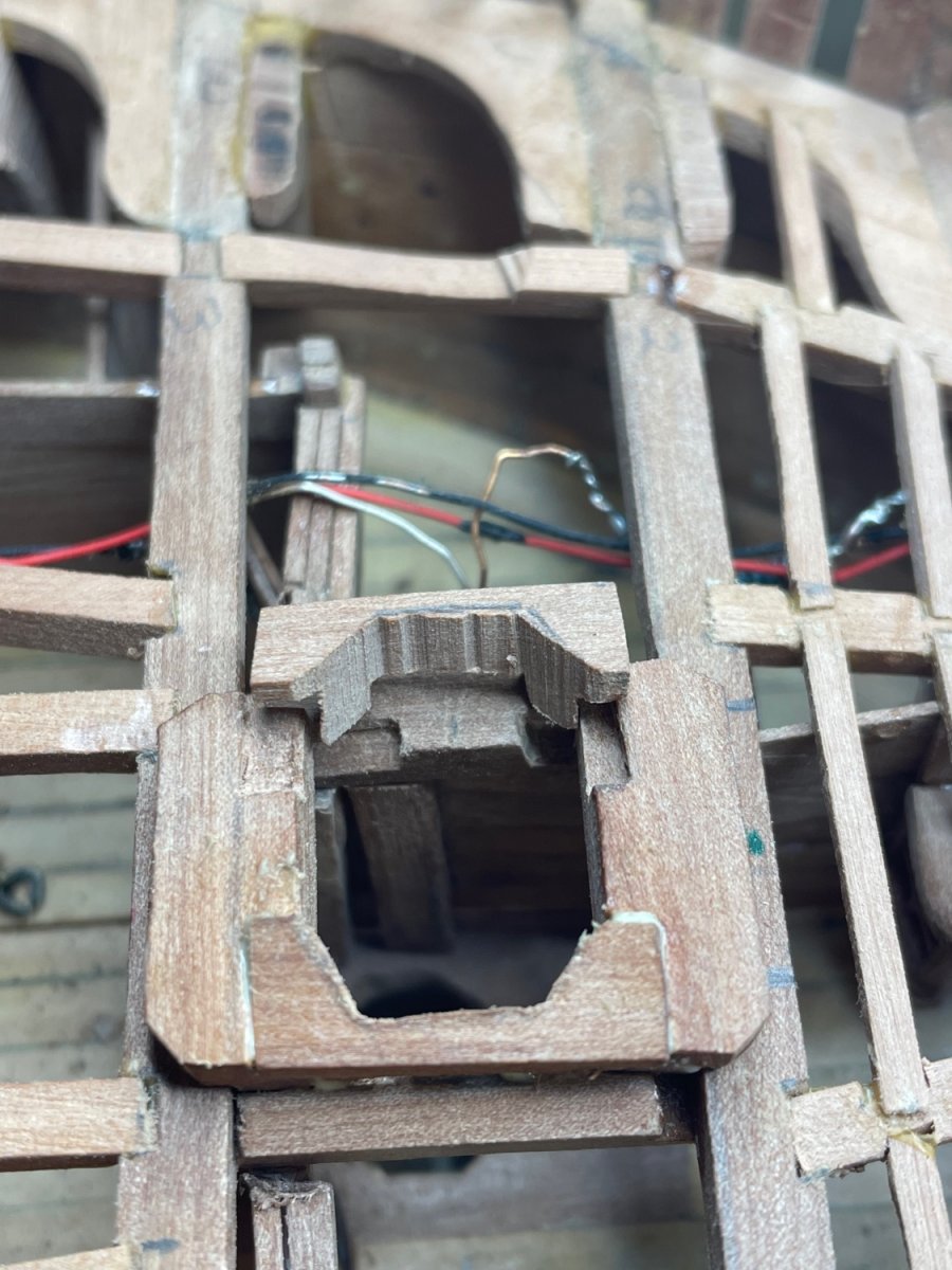
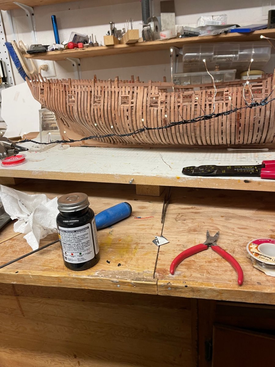
Note also the wires for lighting the lower deck laid in a trough cut into the deadwood and tunneled through the keel. Not sure yet what I’ll do with them from here, but will probably run them along the keel and rout them through the aft pedestal and through the mounting board and then out through the base of the case to a switch. Hopefully when completed there will still be an intact circuit.
- mtaylor and Kevin Kenny
-
 2
2
-
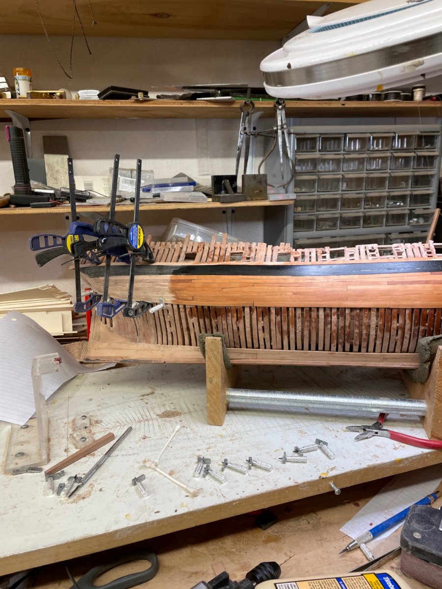
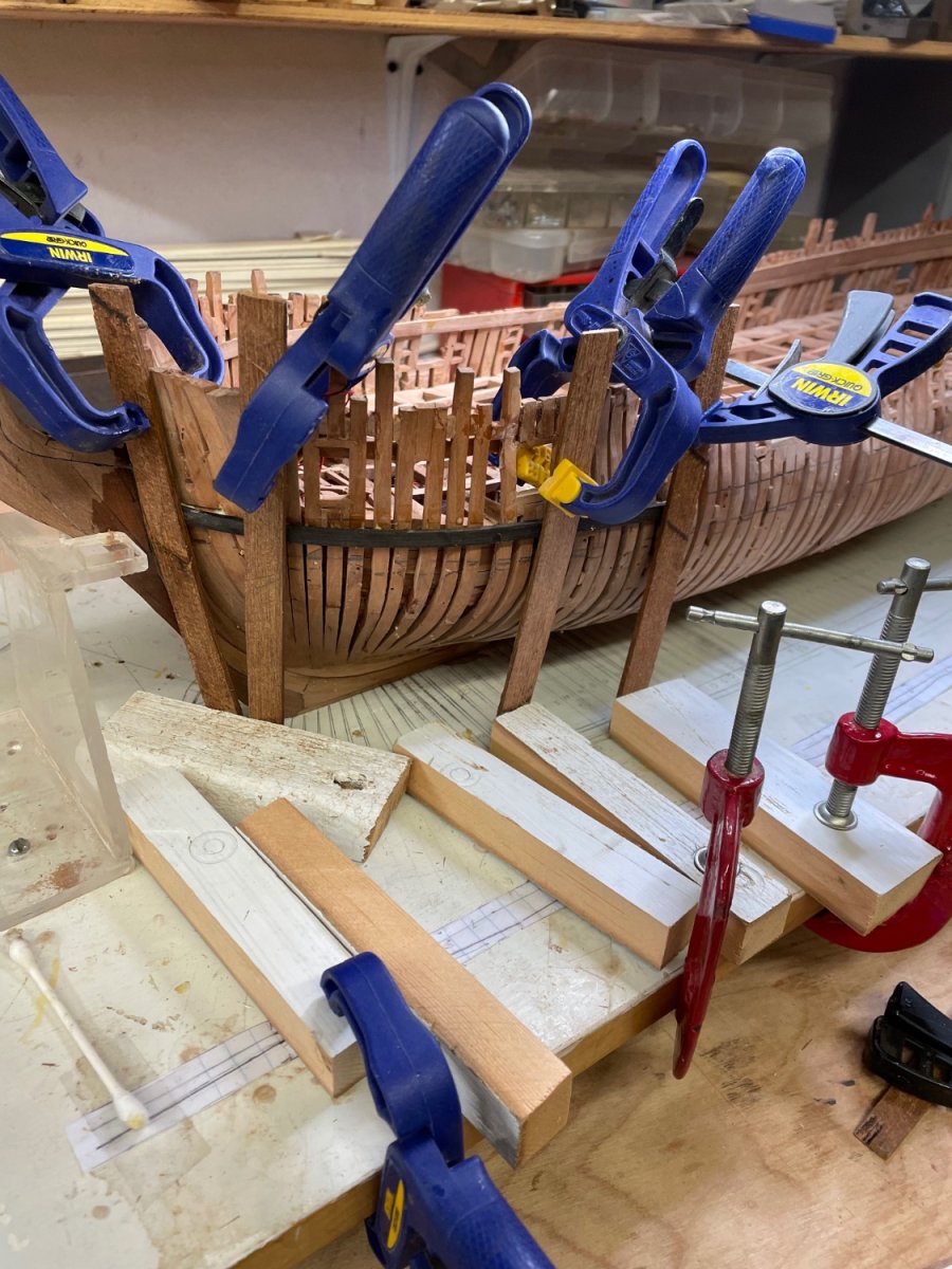
Progress on port side interrupted by a frame faring error not appreciated when applying #11. No good options other than replacing that plank. This was a challenge! But with the help of Isopropyl alchocol, a Dremel router bit and small chisels, the plank came out. After cleaning the site with care not to damage adjacent planks, the replacement plank solved the original problem.
- Saburo, GrandpaPhil, dvm27 and 2 others
-
5
-
On 9/19/2022 at 4:55 PM, druxey said:
For drawing, wood, a pair of parallel pliers work better.
What brand and jaw config would you recommend?
On 10/25/2022 at 6:29 AM, Kevin Kenny said:Henry i thought you had gotten one.
I did. The one you recommended. Just following up on Druxy’s advice. In the meantime, I am trying to get Dave at the Lumberyard to tell me if my recent wood orders were quarter sawn and whether he has Juniper.
Henry
-
-
-
-
I hate it when the build falls off your lap onto the concrete floor.
- gjdale, Landlubber Mike, mtaylor and 1 other
-
 4
4
-
-
-
-
-
Coming along. I’ve just ordered a draw plate from Jim Byrnes as my several plates are not as precise as I’d like. But I can’t seem to find a pair of drawing pliers. Anyone know of a vendor?

- GrandpaPhil, yvesvidal, bruce d and 3 others
-
6
-
-
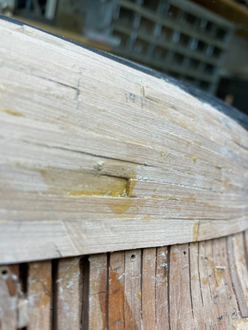
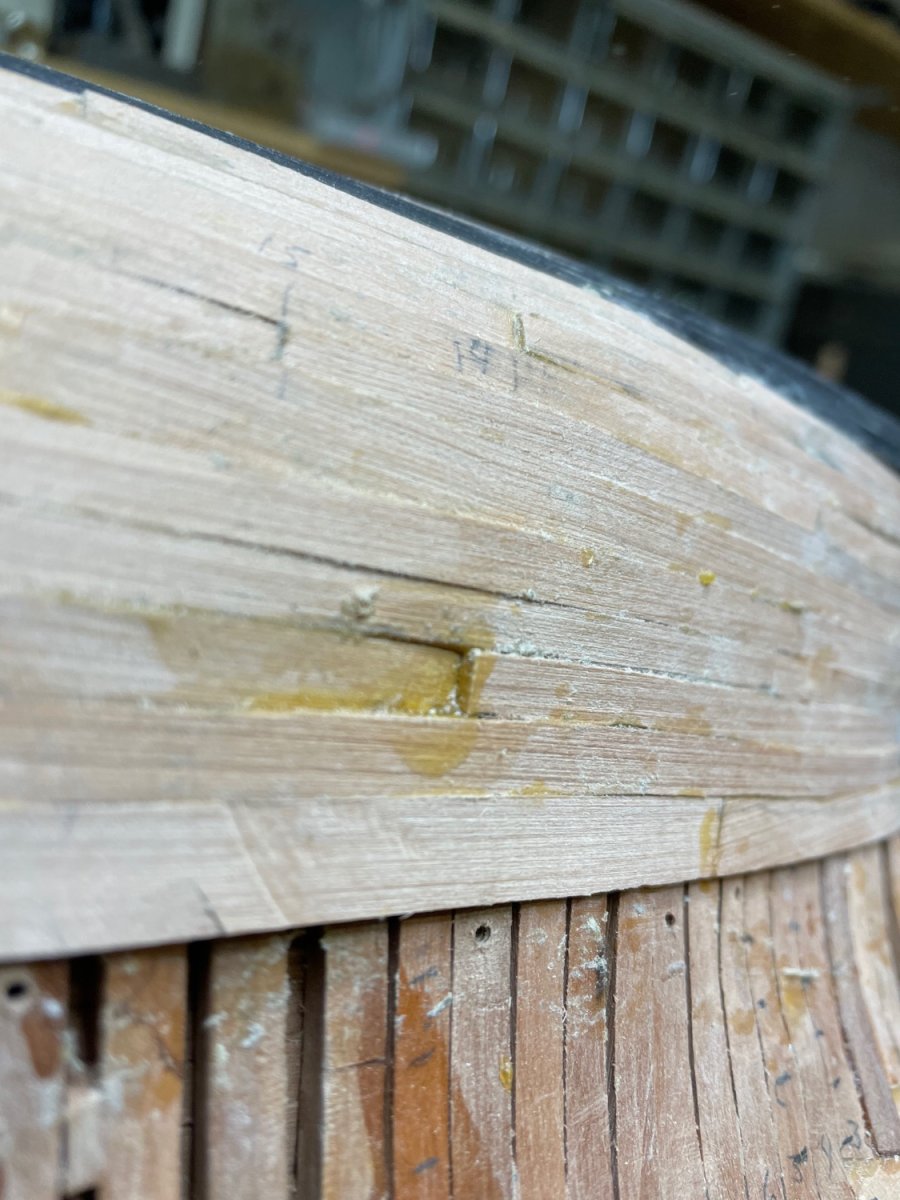
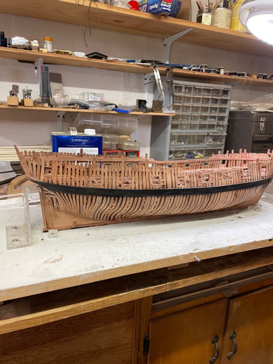
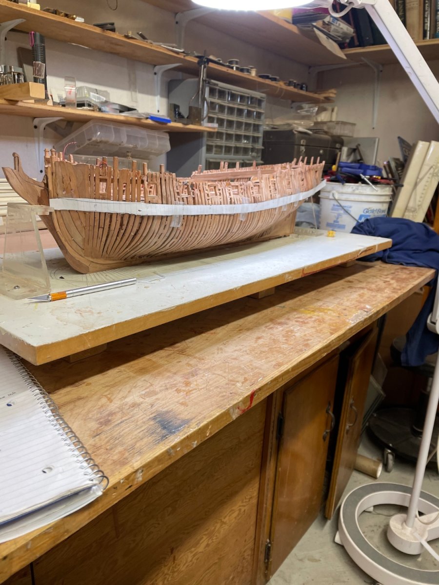
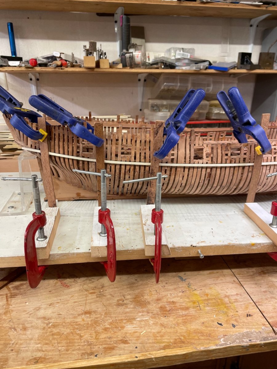
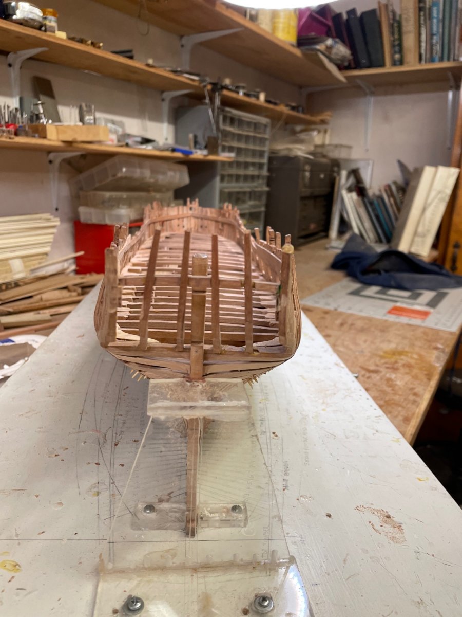
Greg, the text on page 14 shows a drawing of an “apparent reversal of the sheer curve”. If I take the measurements off the plan, they produce a real reversal when applied to the model. The photo below shows the wake as applied with two lines marking 1) the upper edge as cut which conformed to the plan, and 2) the line that would produce a smooth curve. Which is correct??

-
-
-
-
-
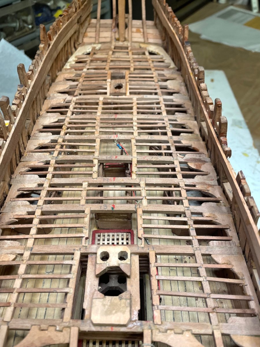
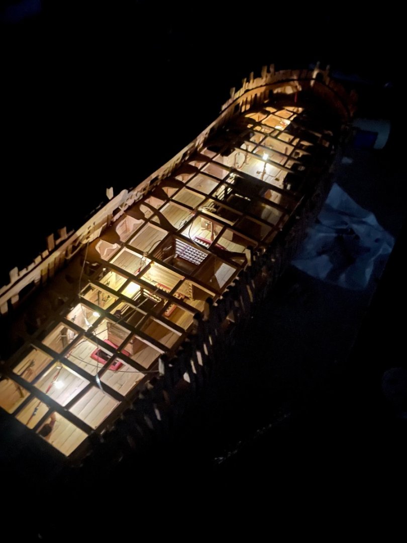 Once the starboard deck is planked, the actual lights will be mostly hidden. The camera shows the lights more intense than they appear in reality. This is my second iteration. The first had more lights and longer stalks that were to be put in the cabins. But it proved too tedious with many shorts between adjacent soldered terminals and wire breakage. So this is a simplified version, which seems adequate to permit some visibility of lower deck details once the upper decks are installed.
Henry
-
-
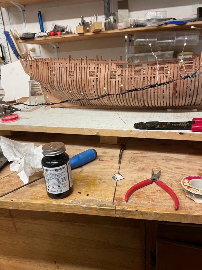
I decided to experiment with micro LED illumination of the lower deck. Thus a pause in construction while I learn what to do. Purchased some micro LED’s which came with a separate bunch of resisters. Each LED came with 3” set of leads. Each positive lead is soldered to one of the resister leads, the other end of which is then soldered to a connector wire (red) of 28 ga insulated 36 v 5 amp colored wire. The negative LED lead is soldered to a black connector wire of similar specs. This was repeated at intervals, most on short stalks intended to run beneath the portion of main deck framing that won’t be planked, with a few long stalks to bring into more confined areas such as the crew quarters. The resulting string is shown powered by a switch box containing 2 1.5 v batteries.(double A). Each soldered junction is coated with liquid tape to prevent shorting against adjacent connections, which I found to be a big problem. The string will then be fed through an aft frame space and brought up to the under side of the main deck framing and secured with CA. At this point, the ledges can be added. We’ll see
-
-
-
On 6/15/2022 at 6:57 AM, hdrinker said:
For reasons I think relate to my interpreting the stern extension of the half breath plan onto the building board, my outer counter timbers don’t square up to the wing transom when viewed from aft for parallelism with the quarterdeck transom temporarily installed. So to fix this error, I need to add and subtract to and from the outer counter timbers so they align properly with the quarterdeck transom. Or…..I could, I suppose, remake the whole stern. Any advise would be welcome.
Didn’t remake the stern but after a few XM adjustments to the outer counter Timbers, things ended up OK.
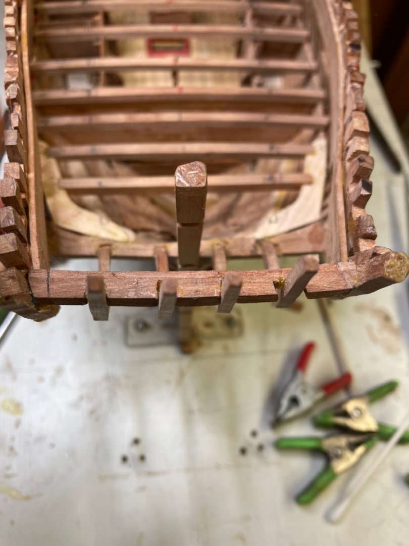
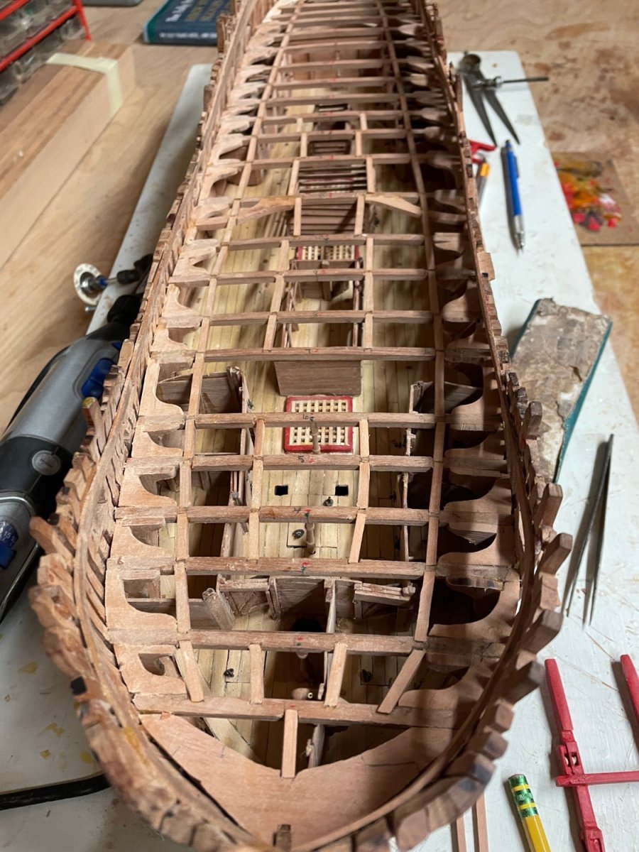
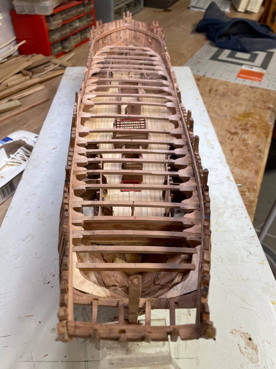
Now to start the main deck framing, using lessons learned from the lower deck. First thing was to lay out the line for the outer carlings, so they’re both symmetrical and make a smooth curve. I think it will look much better than my previous effort.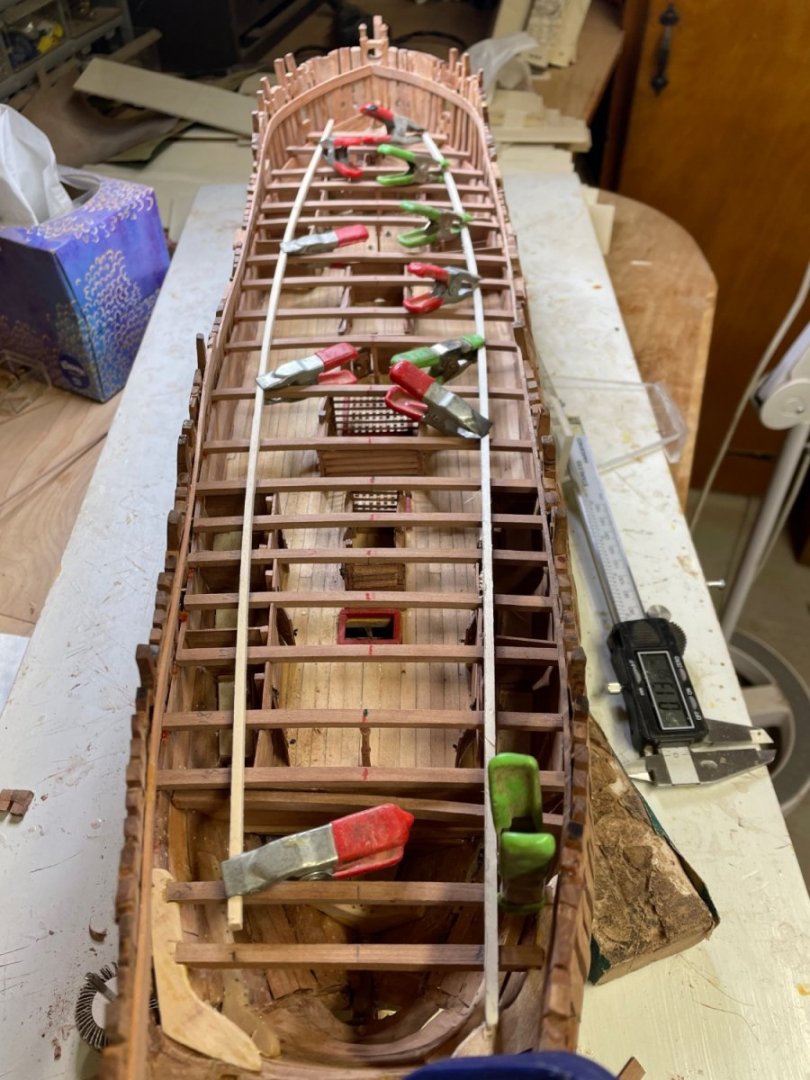

- Saburo, KARAVOKIRIS, mtaylor and 4 others
-
7


Pegasus by hdrinker - 1:48 - POF - Swan practicum
in - Build logs for subjects built 1751 - 1800
Posted
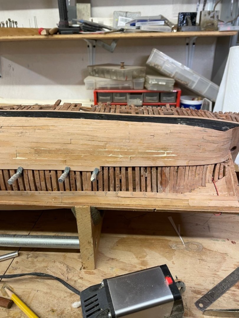
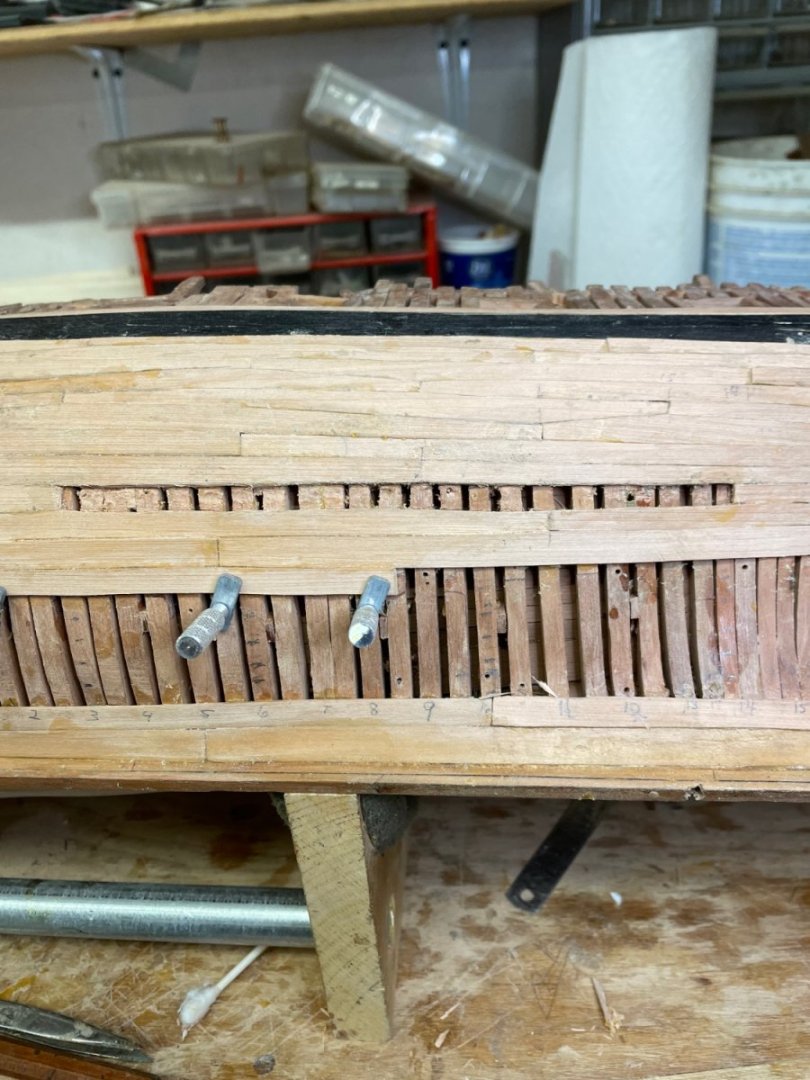
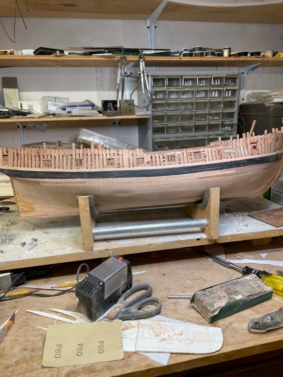
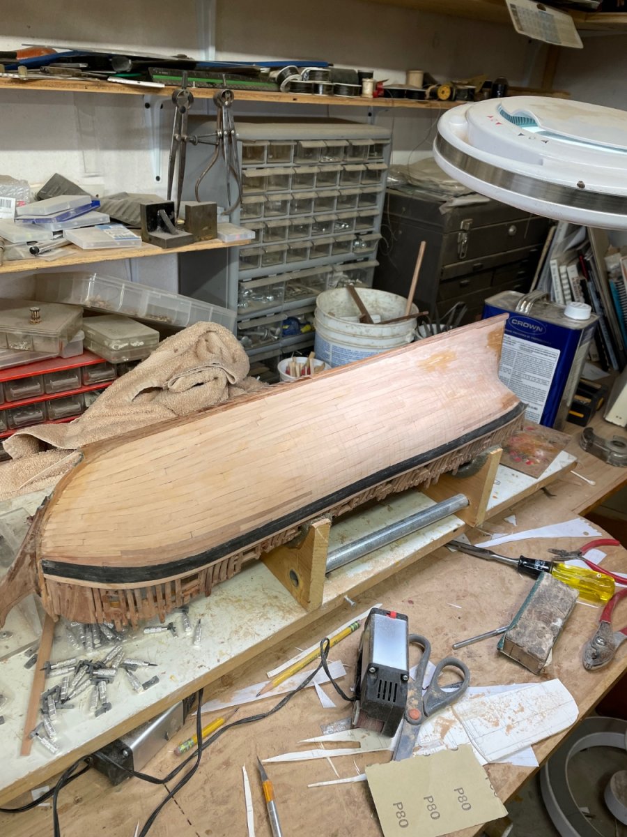
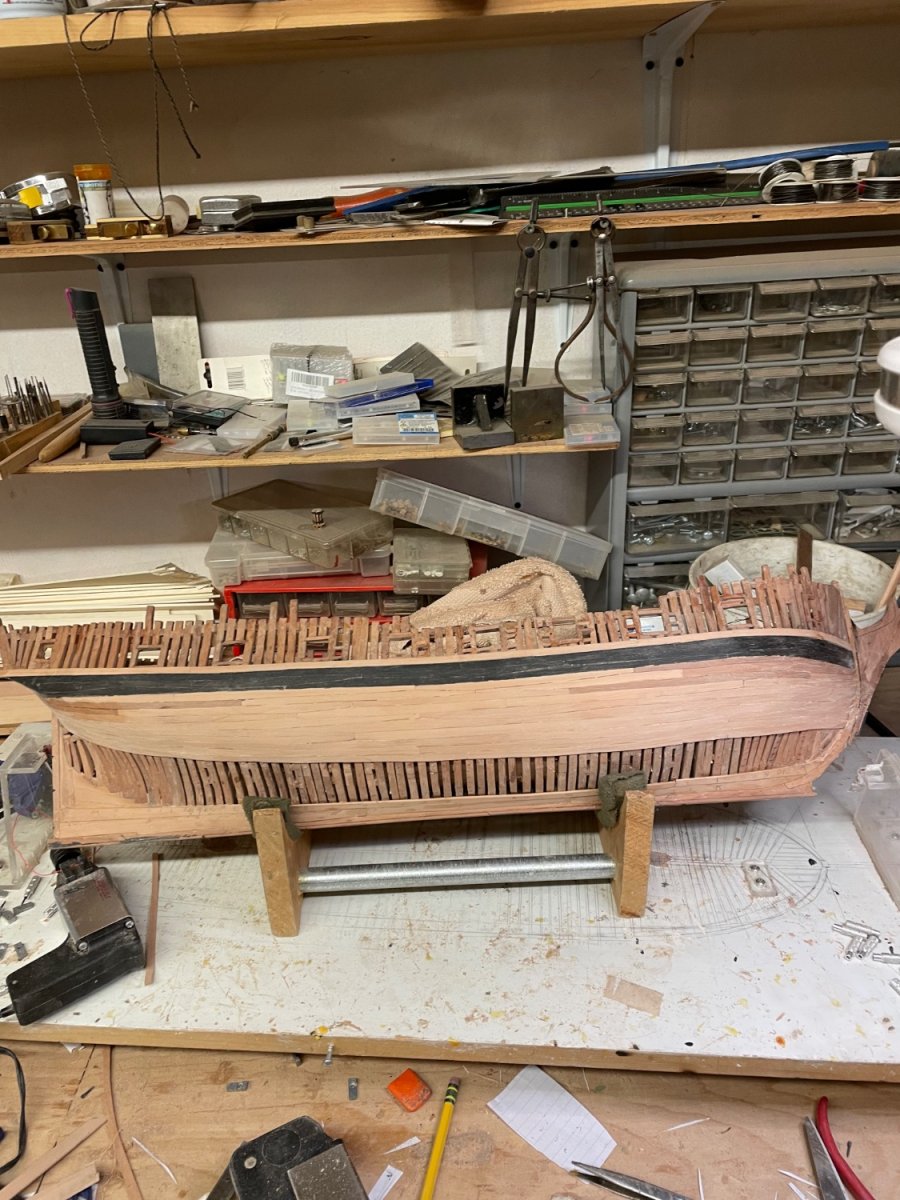
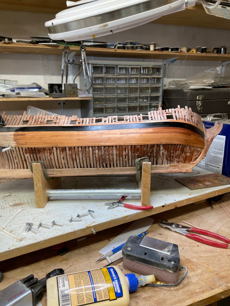
So far, so good with the light circuit. Starting the tree nails. Planking complete on both sides and preliminary sanding.