


hdrinker
-
Posts
170 -
Joined
-
Last visited
Content Type
Profiles
Forums
Gallery
Events
Posts posted by hdrinker
-
-
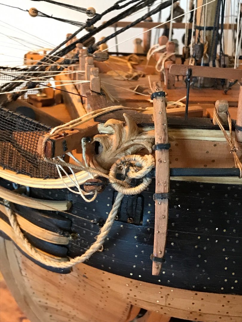
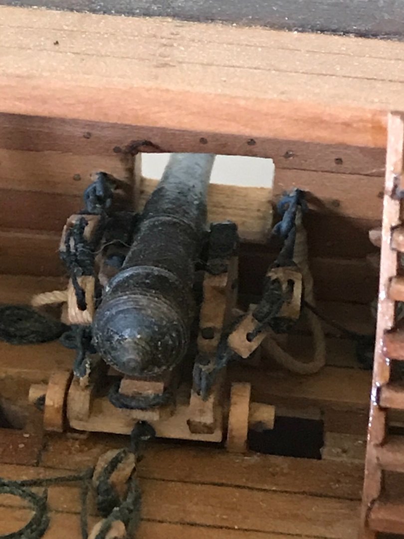
Kevin, thanks so much for your kind attention to my riding bit delemna. My problem actually is not the location of the pins, but their length. Maybe if I knew the height of the pin tops relative to the upper deck, I could apply that measurement to my model and come up with the correct pin length overall. Even a photo from the side of a completed model would help, if it showed the riding bits.
Henry -
-
-
-
-
Hi Kevin,
I am using a soft silver solder paste, yes.
- Saburo, mtaylor and Kevin Kenny
-
 3
3
-
-
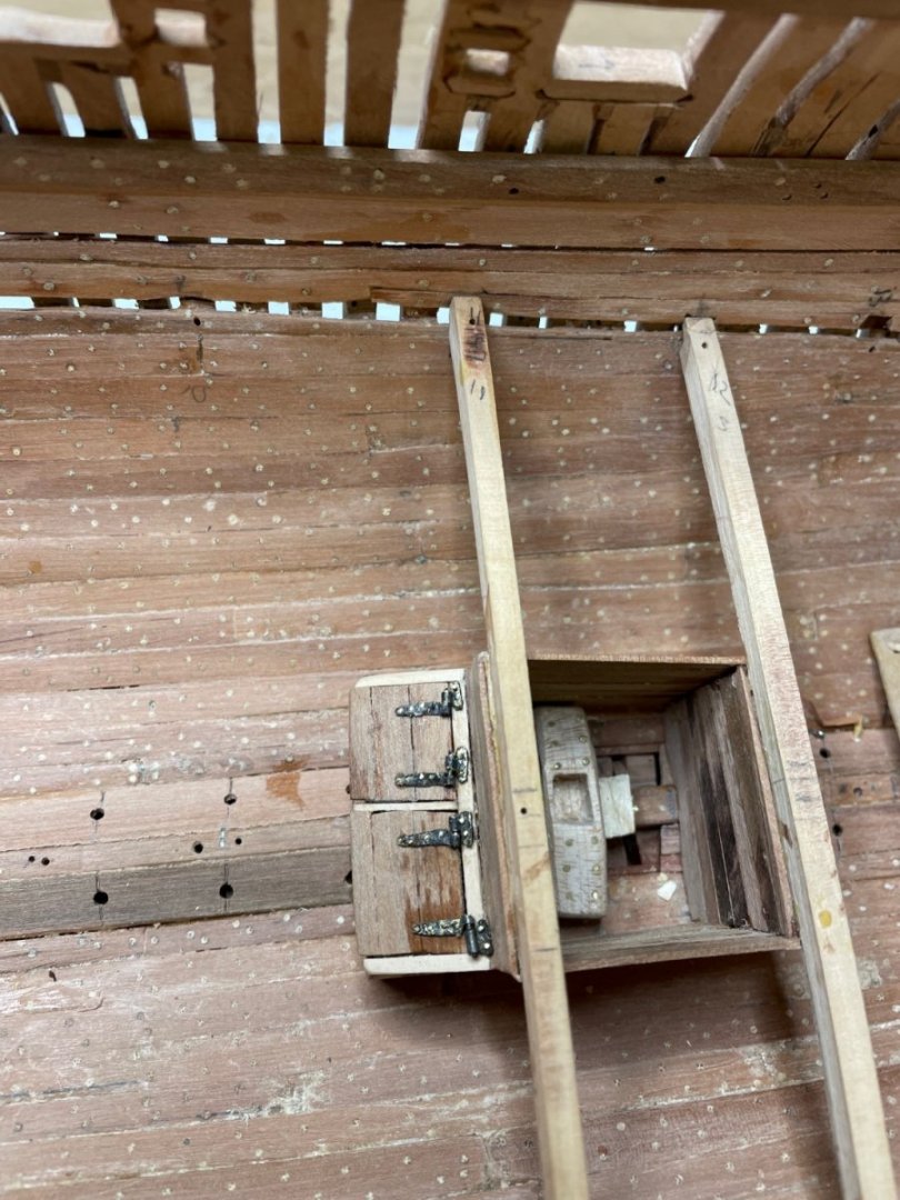
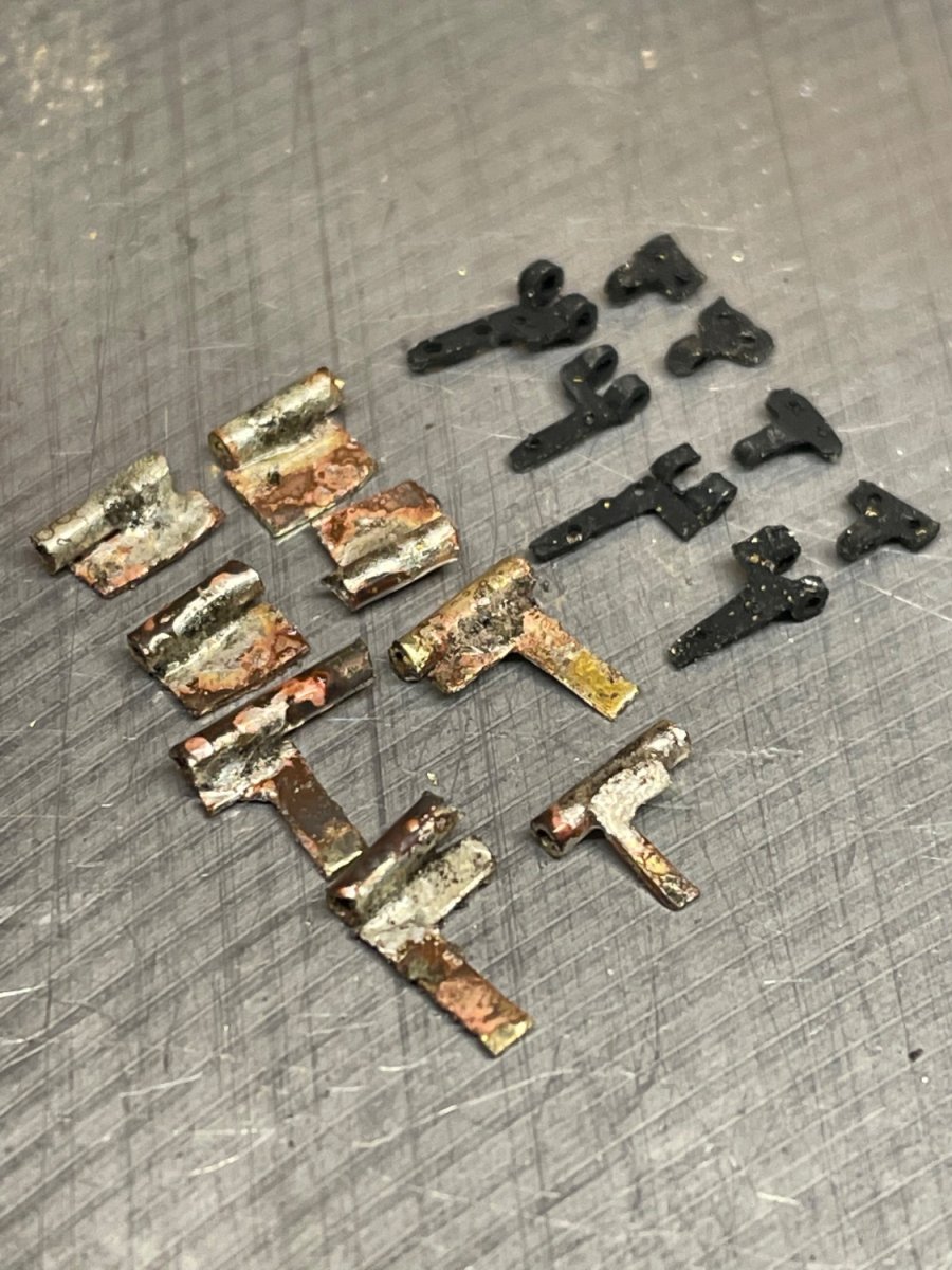
Very hard to scale real hinges down. So far, all are too big. Just received tubing .0126 “ iD. We’ll see if I can work these down to 1/48… When I started this build, I had the plans for framing and spars provided with the 1st volume of David and Craig’s series. But they don’t provide framing for the decks or deck furniture. Where are those available?
-
-
-
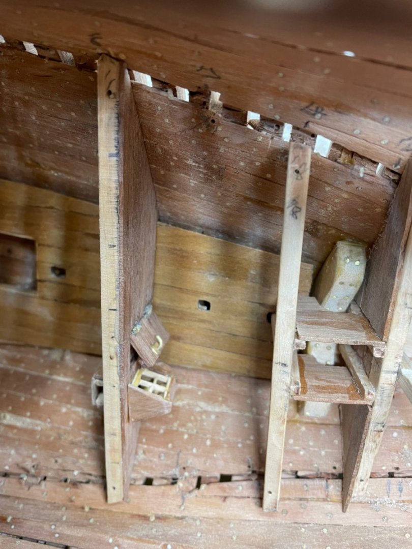
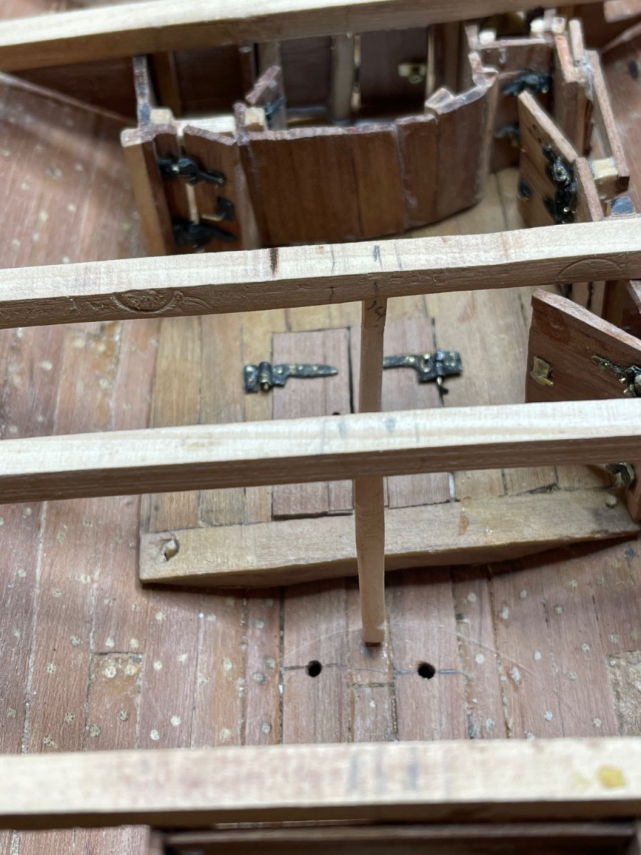
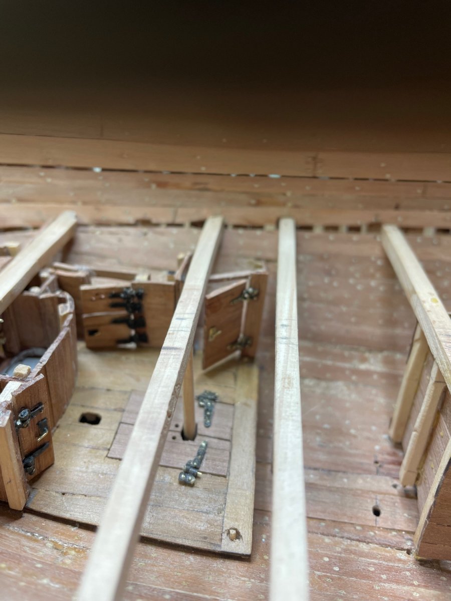
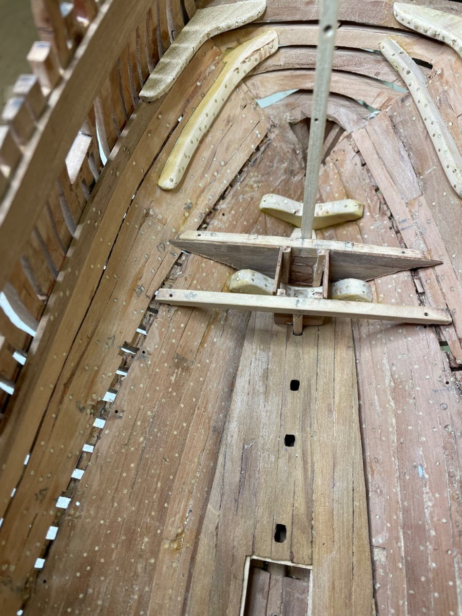
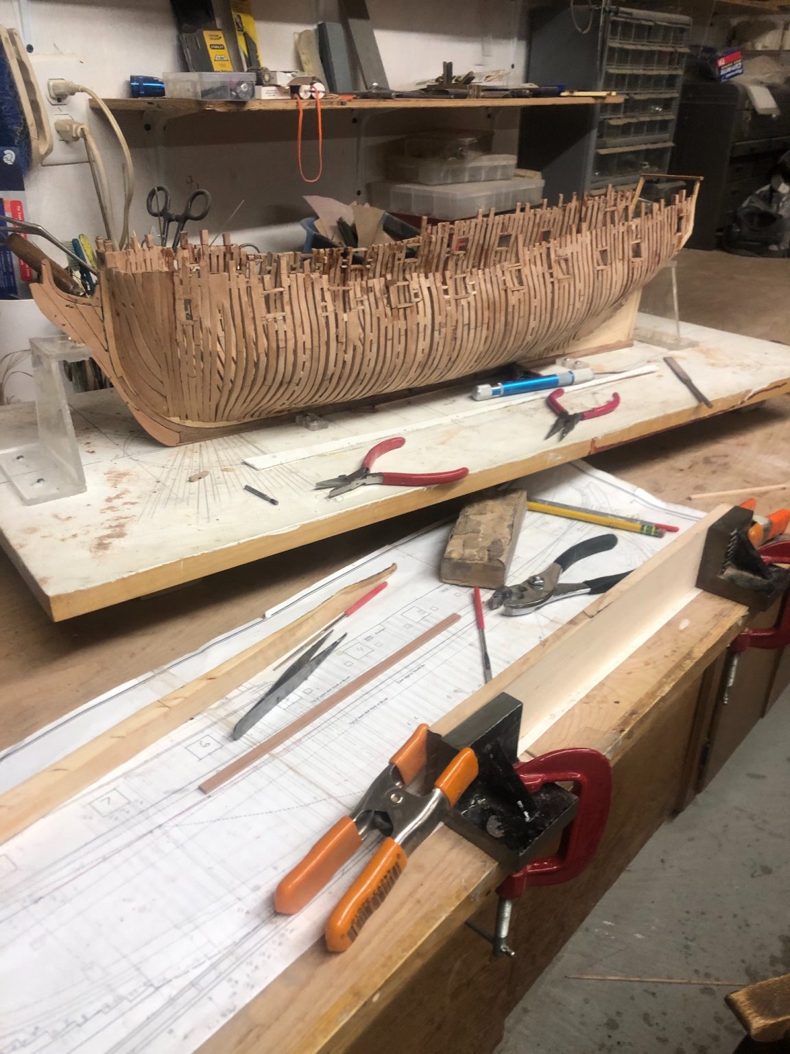
Making progress on my second iteration. So far I’ve followed the posts of Kevin Kenny and Stuglo with great appreciation and admiration. Your skill level is way beyond my own. I find myself spending hours on improving my hinges, trying to make them smaller and smaller. The key has been perfecting my silver soldering technique. The stronger the joint, the more I can file them down to the desired size without the joint failing.
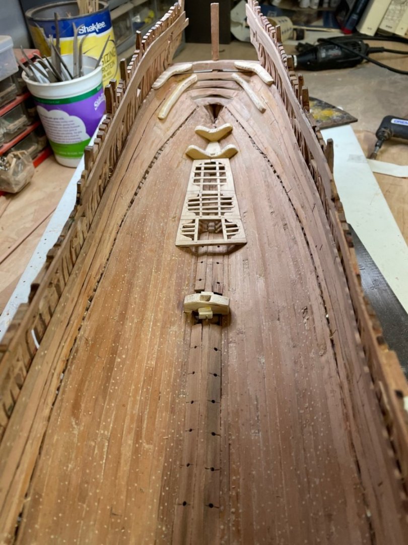
I’ve not yet made a decision on how, and whether to display the interior in the final product. So for now, I’m doggedly applying all the interior detail. If nothing else, it’s a fun process and serves to improve my methods. After all, Isn’t that what it’s all about!
It’s a cold morning in eastern Massachusetts. Great weather for making progress in the model shipyard.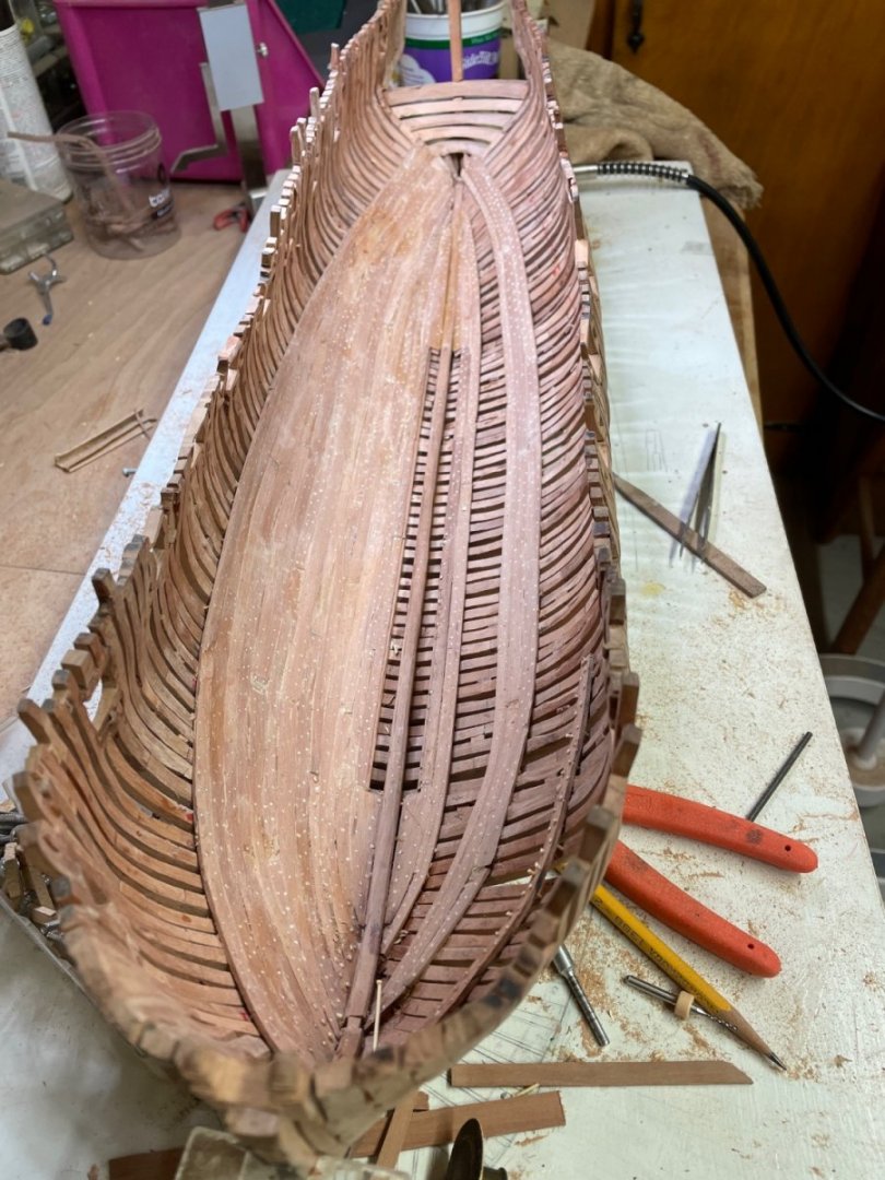

- Keith Black, dvm27, KARAVOKIRIS and 7 others
-
10
-
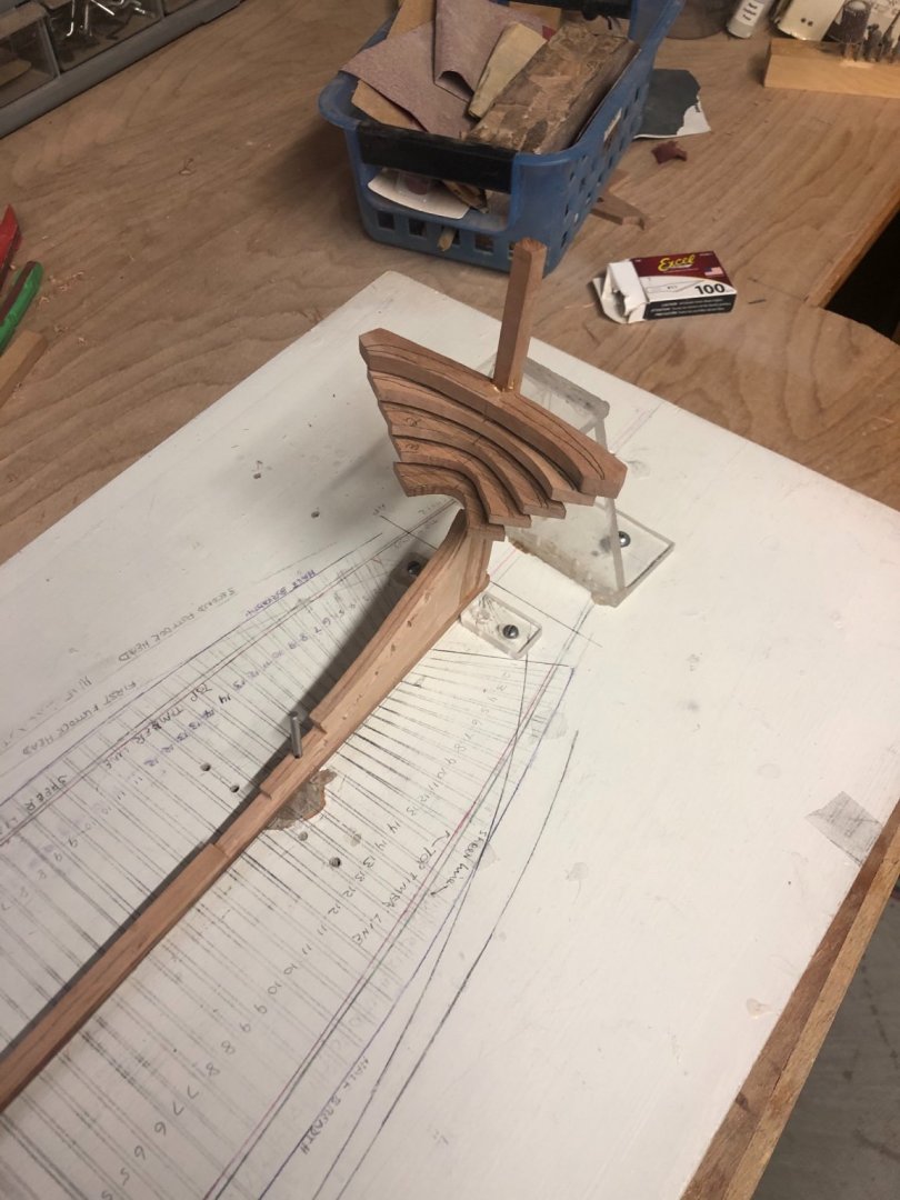
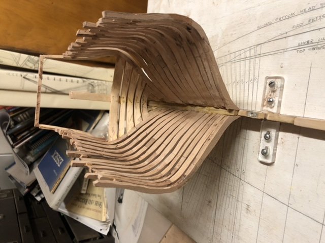
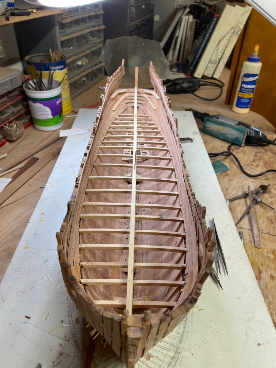
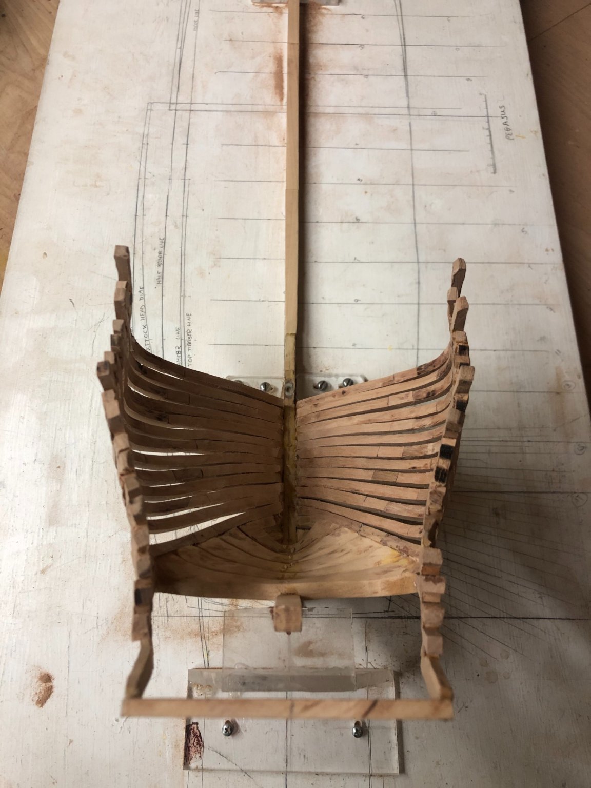
I did start again. Added a digital height gauge and digital angle gauge to my gadget box. Those have made certain things more accurate. Payed much more attention to height of breath this time as well as the top timber alignment, and as a result, some of my earlier alignment issues have not been repeated. Now that the cant frames are in place fore and aft, I’ll focus on getting the right sheer of the ports. I put the foremost and after most ports in by measurement and have made a template of the port sheer line as a check going forward.


- GrandpaPhil, gjdale, mtaylor and 5 others
-
8
-
That’s wonderful to hear and very encouraging. I’m going back over the plans, the tutorial and my framed version recording in a journal where the errors probably occurred and plan to spend much more attention to detail next time. Even though it’s a bit foreboding to begin again, that’s the plan. I’m learning a lot. Not by any means is the first run waisted!
-
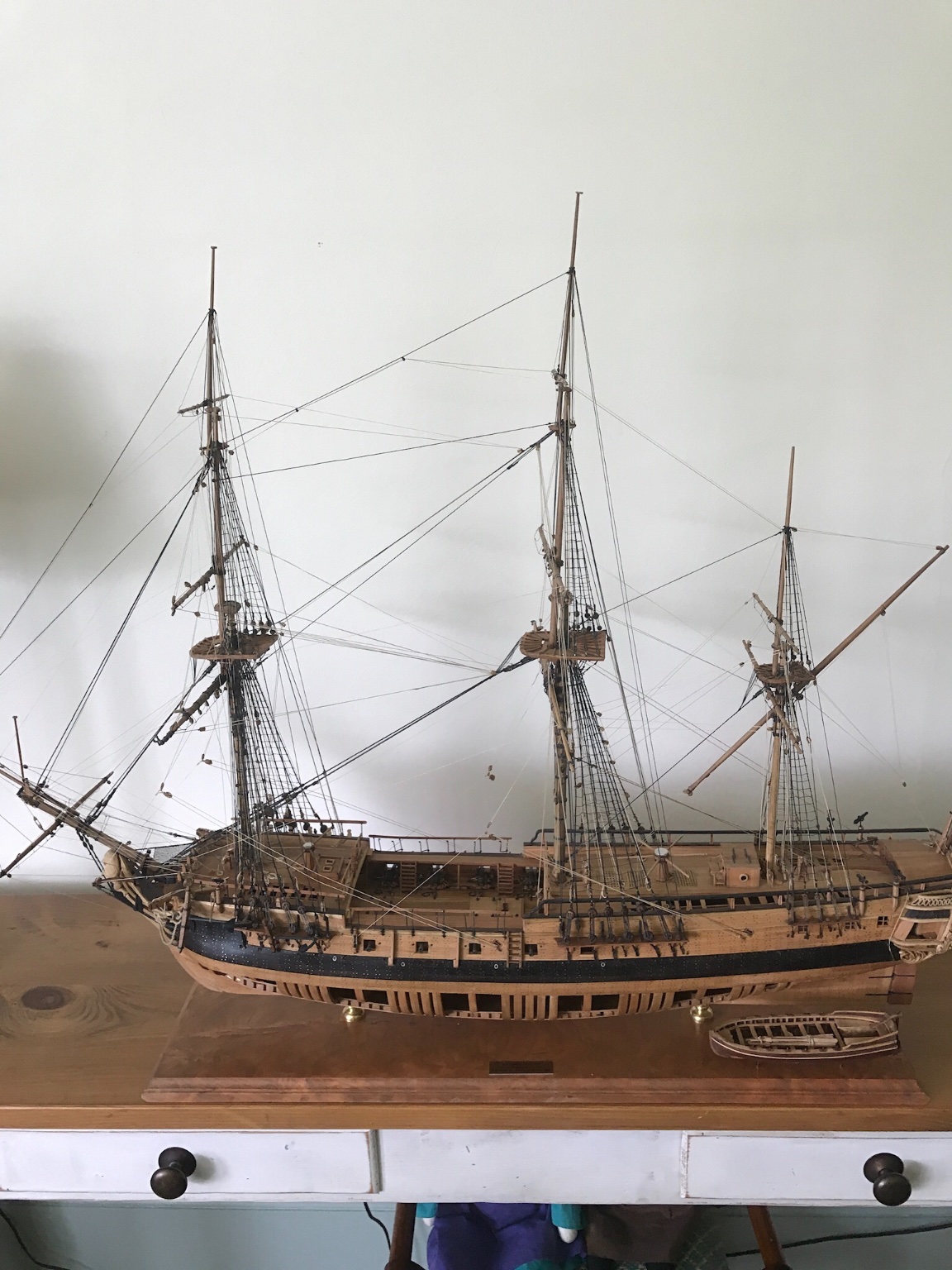
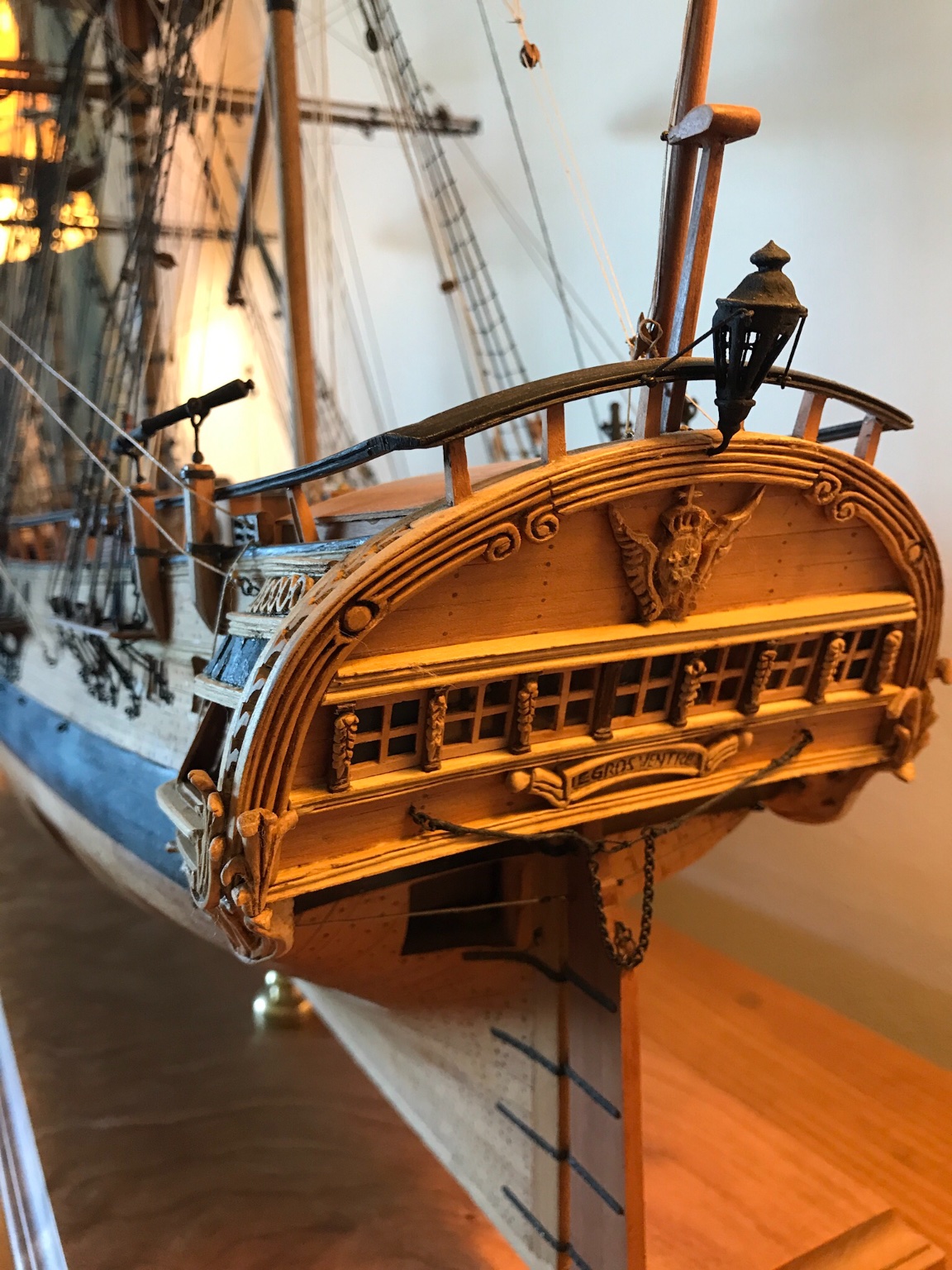
Thanks for that advise. But why settle? I don’t have room in the house, as my wife likes to remind me, for more ship models. I kept a log of my ‘Gros Ventre” and didn’t seem to have avoided the same issues this time. As you will appreciate from the photo of that POF, the issues for me have not been what happens after the framing. I’d like to feel I got it right....


- Saburo, ccoyle, GrandpaPhil and 4 others
-
7
-
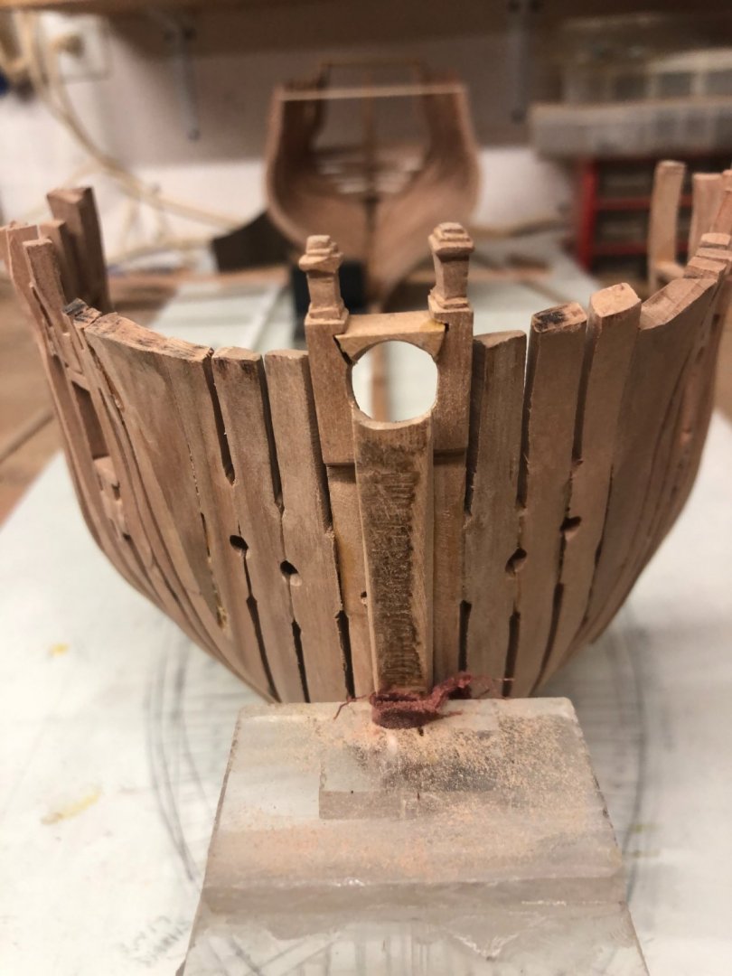
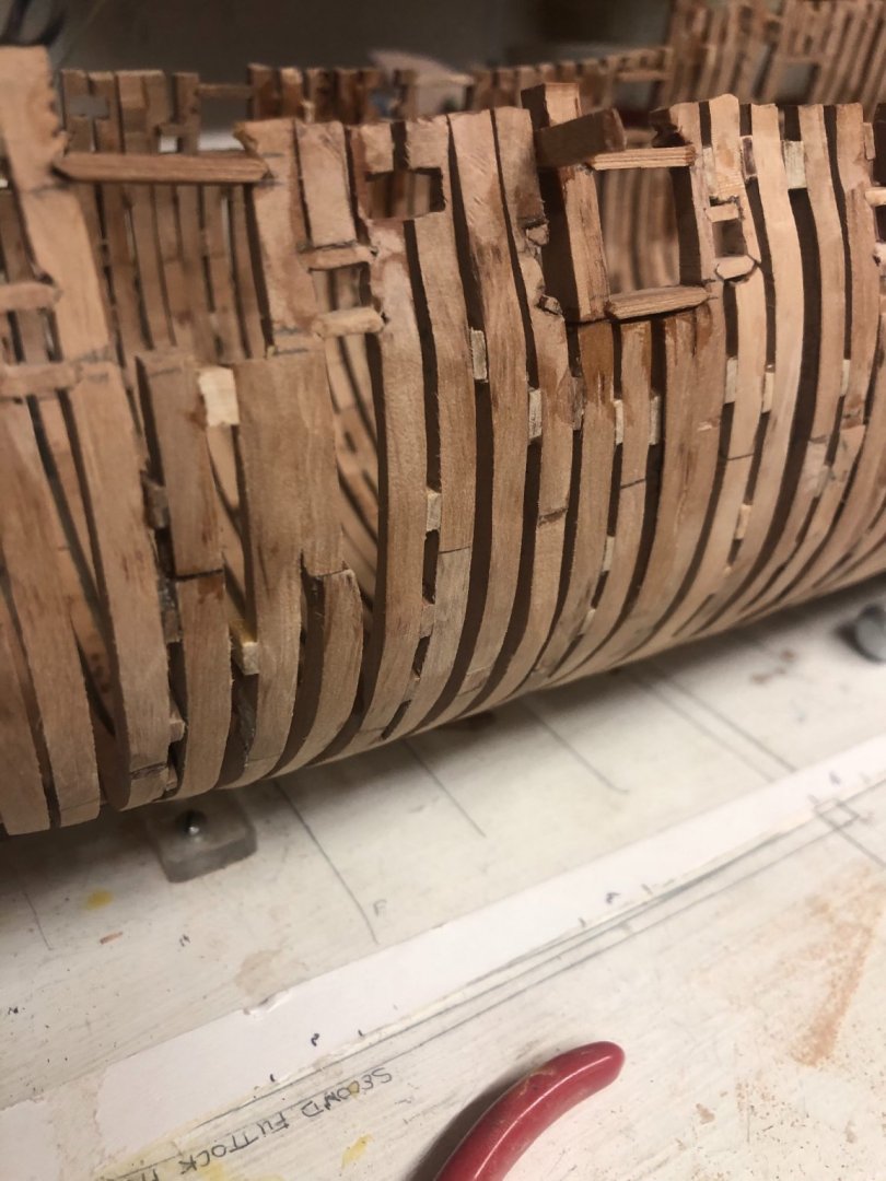
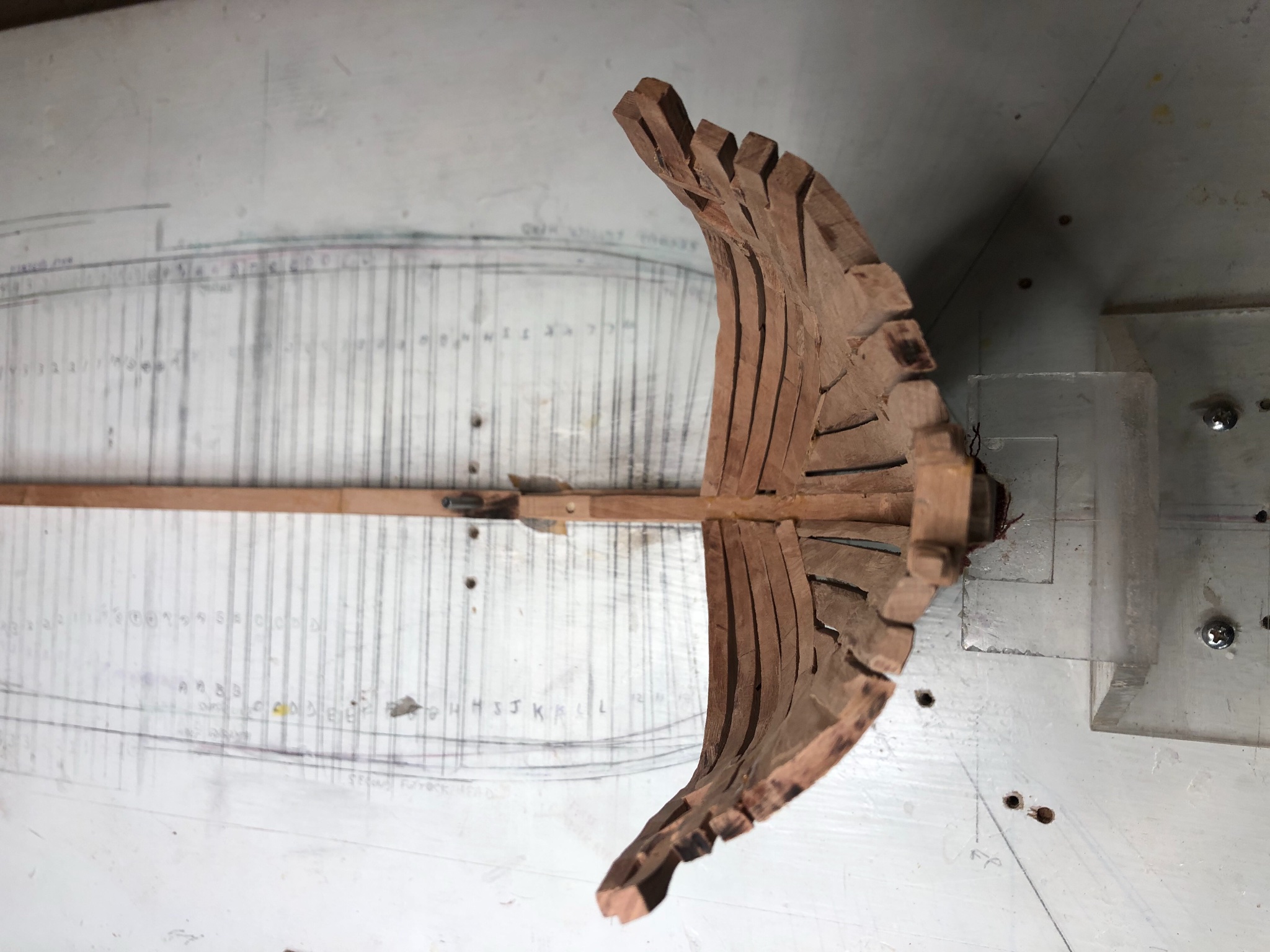
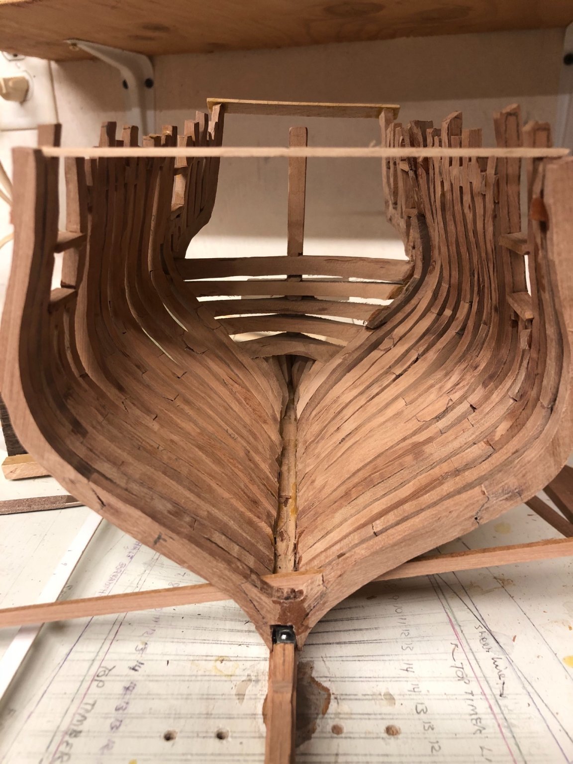
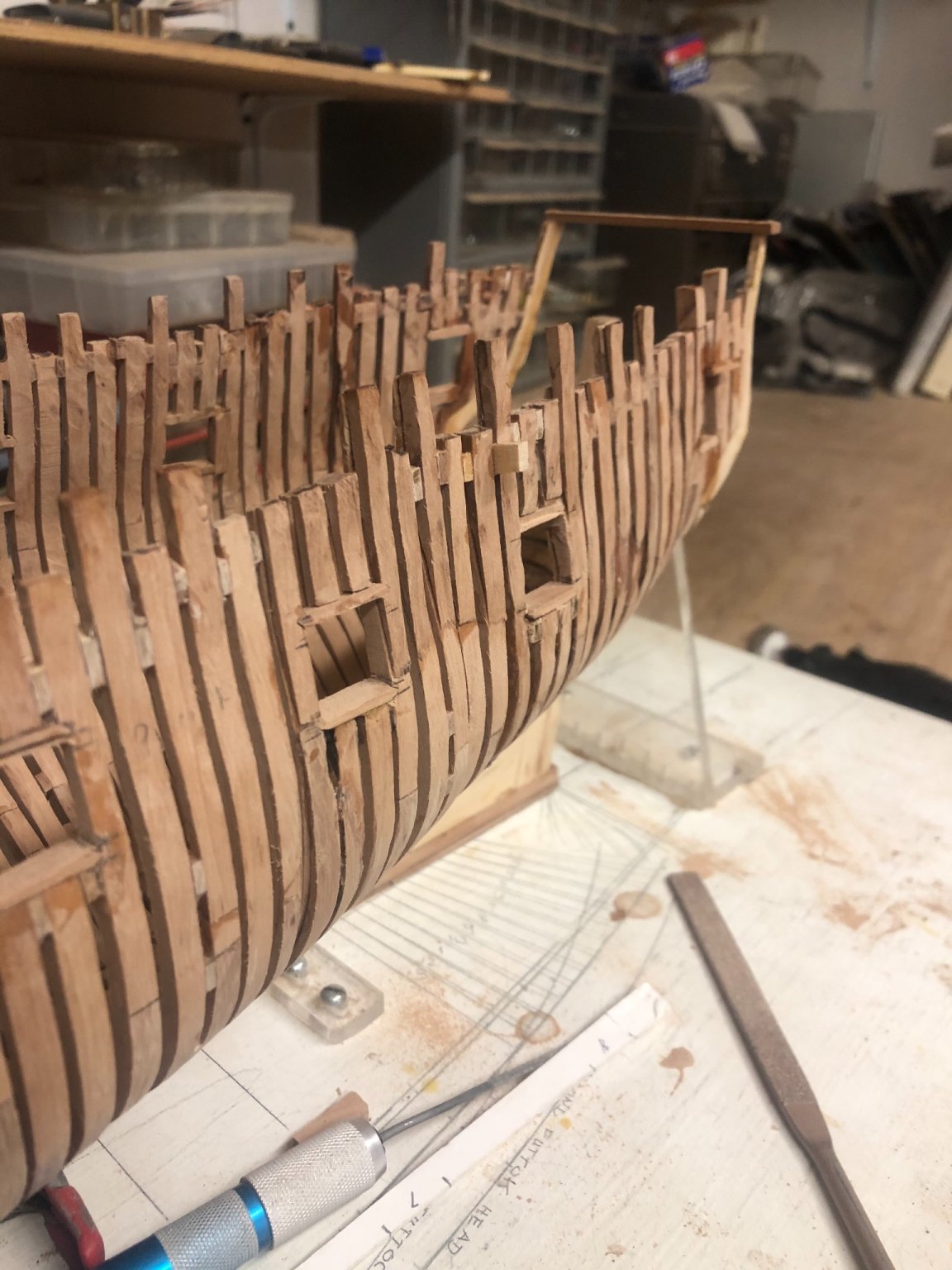
Note the undulating top timber line. I should have remade the offending cant frames at that point but was unsure of the eventual top timber contour, and so I decided to make corrections at the end.

- GrandpaPhil, Ron Burns, mtaylor and 2 others
-
5
-
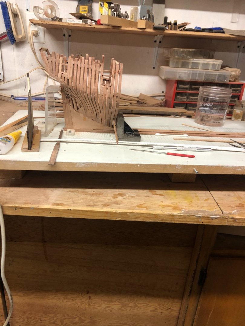
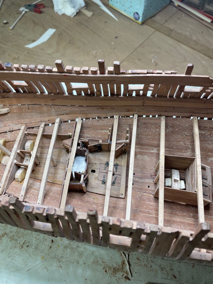
I’ve now completed the hull framing and find it less than satisfactory from a visual point of view but structurally fine. I would be embarrassed to leave it unplanked! The two biggest issues were#1: an undulating top timber line and #2: port alignment not true to sheer. As a result, I’ve revised the ports and have had to add and subtract considerable material to create a smooth top timber line. Wish I’d completed the framing before cutting in the ports. A template of the sheer could then have been used to insure proper port alignment. I’m tempted to begin again, having some idea for how to avoid these mistakes now. I’m more interested at this point in my skill development in the process than the final product.


-
Kevin, I very much enjoyed your videos. Beautifully done. Your skill level is understated. I am just finished the hull framing of Pegasus. My attention to detail has been inferior by far to yours. The two most significant problems I encountered were #1: maintaining a smooth top timber line, particularly with the aft cant frames and #2: alignment of the ports consistent with the sheer. I cut the port notches as I went and the end result was poor. I decided to redo all the ports. I think I would prefer next time to cut them after the framing was complete by drawing the correct locations relative to the sheer beforehand. The top timber line correction was completed by adding and subtracting material. While the end result is satisfactory from a construction standpoint, I would not want to leave it unplanked in the end.
Your work makes me consider starting again from scratch. My first two POF models were undertaken as much for the end result as for the process itself. This one was purely for the process. Well done!Henry Drinker
-
On 6/24/2020 at 1:39 PM, hdrinker said:
I’ve been scratch building POF models since about 1995, having retired 7 years ago as an orthopedic surgeon. So my projects have been drawn out quite a bit until more recently. I started with the USS ESSEX, following the Practicum of the late Portia Tachajian, followed by the Delacroix “LE GROS VENDRE”. David Antscherl’s Practicum on the Swan Class intrigued me as it represents the methods used by the English in the 18th century, as compared to that of the French of the same period. I also met David at the NRG annual in New Bedford last year and was drawn in both by his personal appeal as well as his amazing attention to detail and methodology.
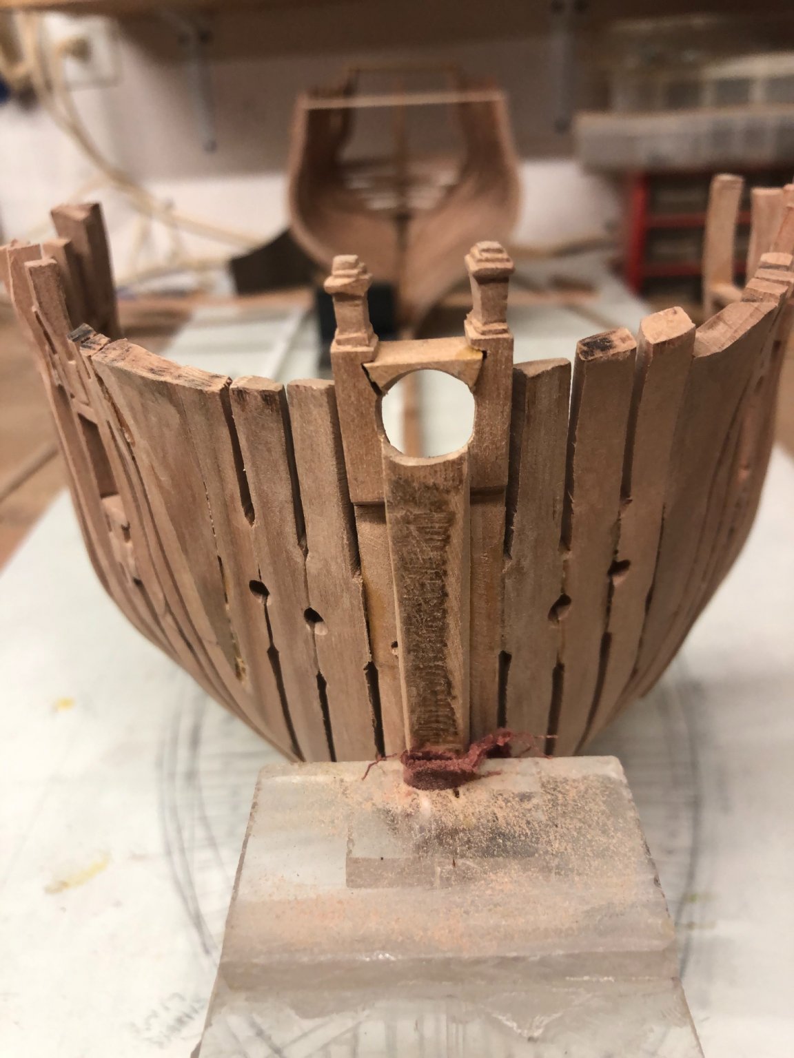
So, I’ve kicked this project off, sticking to the Antscherl Practicum in 1/48 of the Pegasus, and have progressed as far as completing the bow and stern framing and beginning the full frames. The bow and stern are roughly fared and sanded. I’m fitting chicks between Cutty is and have decided to keep the sided dimension of full frames equal from floor up instead of dIminishing.
I admit to being a little confused about full frame spacing and sided dimensions. Perhaps the reader could enlighten me. The text seems to indicate the use of spacers on either side of each futtuck joint, and seems to say that the spacers are as thick (sided) as the frame, at least at the floor level, and indicates the frames to be cut from 10” stock. I assume there to be similar spacers between each frame pair as well as between each frame half. Adding all that material up at those dimensions, and locating the station lines on the elevation plan as defined in the text as being mid way between the two frame halves, I understand, perhaps mistakenly, the space between each set of station lines to extend from midway through the first frame pair spacer, through a whole frame pair , to mid way through the next frame pair spacer, or the equivalent of two full frames. Using the dimensions above, the space occupied by all that exceeds the length between stations on the elevation plan by a considerable amount. So something is wrong with my interpretation of the text, I fear.
HD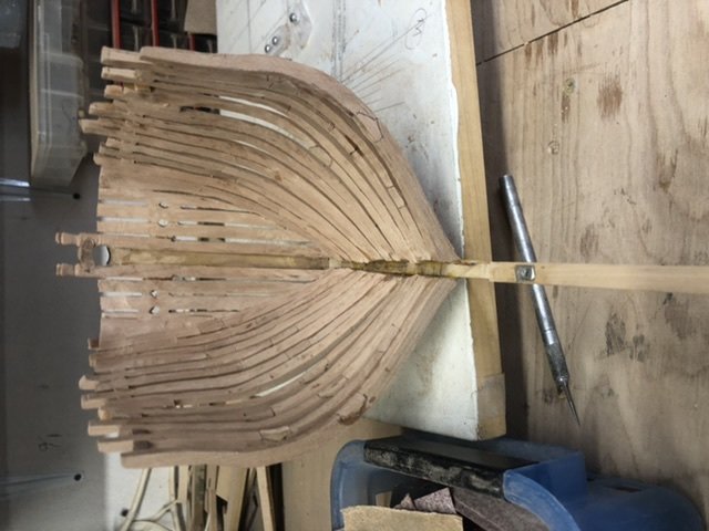
- Saburo and Landlubber Mike
-
2
-
I’ve been scratch building POF models since about 1995, having retired 7 years ago as an orthopedic surgeon. So my projects have been drawn out quite a bit until more recently. I started with the USS ESSEX, following the Practicum of the late Portia Tachajian, followed by the Delacroix “LE GROS VENDRE”. David Antscherl’s Practicum on the Swan Class intrigued me as it represents the methods used by the English in the 18th century, as compared to that of the French of the same period. I also met David at the NRG annual in New Bedford last year and was drawn in both by his personal appeal as well as his amazing attention to detail and methodology.
So, I’ve kicked this project off, sticking to the Antscherl Practicum in 1/48 of the Pegasus, and have progressed as far as completing the bow and stern framing and beginning the full frames. The bow and stern are roughly fared and sanded. I’m fitting chicks between Cutty is and have decided to keep the sided dimension of full frames equal from floor up instead of dIminishing.
I admit to being a little confused about full frame spacing and sided dimensions. Perhaps the reader could enlighten me. The text seems to indicate the use of spacers on either side of each futtuck joint, and seems to say that the spacers are as thick (sided) as the frame, at least at the floor level, and indicates the frames to be cut from 10” stock. I assume there to be similar spacers between each frame pair as well as between each frame half. Adding all that material up at those dimensions, and locating the station lines on the elevation plan as defined in the text as being mid way between the two frame halves, I understand, perhaps mistakenly, the space between each set of station lines to extend from midway through the first frame pair spacer, through a whole frame pair , to mid way through the next frame pair spacer, or the equivalent of two full frames. Using the dimensions above, the space occupied by all that exceeds the length between stations on the elevation plan by a considerable amount. So something is wrong with my interpretation of the text, I fear.
HD
-
-
On 2/3/2017 at 5:10 PM, Trussben said:
Yeh Gary,
I have made some silly mistakes when cutting out frames, only piece of absolute advice I can definitely give is check the scale every time you print a set out plans for the framing - ask me how I know!!
Ben
Have recently embarked on the Antscherl Practicum of the Swan Class (Pegasus 1/48) and am looking to connect to any willing to share their experience in that project, as there are inevitable questions that arise.
Henry -
Your work is an inspiration to someone who has completed this model by hand without the knowledge and skill to use my milling machine (Sterling). It took 12 years, having started with the original group and Gerard Delacroix’s guidance. Your wonderful results make me want to start all over again. Are you using a CNC SYSTEM? I’d love to see how you make those complex bevels on the hawse timbers and reproduce them for the opposite side!!
- Saburo, PeteB, Edwardkenway and 1 other
-
4
-
-


HMS Thorn by Kevin Kenny - 1:48 scale - Swan-class - David Antscherl practium
in - Build logs for subjects built 1751 - 1800
Posted
Kevin, thanks so much for your kind attention to my riding bit delemna. My problem actually is not the location of the pins, but their length.
So, I measured the distance from the bilge to the top of the lower deck beam #5 in my build and added that to the measurements on your note to the top of the pins and came up with a pin length of 4.069”. Does that make sense? If so, I am left only with the remaining question of where you derived the measurements on your note….
Henry