
HOLIDAY DONATION DRIVE - SUPPORT MSW - DO YOUR PART TO KEEP THIS GREAT FORUM GOING! (Only 36 donations so far out of 49,000 members - C'mon guys!)
×

Kenchington
-
Posts
679 -
Joined
-
Last visited
Content Type
Profiles
Forums
Gallery
Events
Everything posted by Kenchington
-
 Mark a centreline on the building board, then on each of the frame units. Line those up, add Lego blocks and masking tape to keep all square (sanding the slots in the building board if necessary). Then check, check and check again! Small errors in the initial set-up will only get worse as your build moves ahead -- and none of us want that. Trevor
- 32 replies
-
- 3
-

-
- Dory
- Lowell Grand Banks Dory
- (and 4 more)
-
Bulkhead, maybe? Trevor
-
Well that certainly shows plenty of fastenings! Bolts though, whereas the photo that Roland noticed certainly shows treenails. Trevor
-
Hull planking
Kenchington replied to The Bitter End's topic in Building, Framing, Planking and plating a ships hull and deck
The (few) contracts and specifications I have seen tend to say something like "not less than X between butts of adjacent planks" and "not less than Y planks between two butts on the same beam". Regular patterns could be efficient when large, open extents were being planked but it must have needed a lot of thought when working around hatchways, mast partners and the like. Some off-cuts might be useful, when filling in between obstacles. Some longer lengths could avoid a butt here or there but not if they threw off the pattern and drove more cutting somewhere else. Trevor -
There are treenails there but, to my eye, rather few. Some fasten the scarfs, some join the two parts (forward and aft members of a pair). One neat detail is that there are thin boards on the upper face of each rider, presumably to take the wear-and-tear of feet and anything else placed on top of the major strength elements. I would have expected those boards to be fastened with small, iron nails, but there are treenails running through them into the riders. Trevor
-
Without seeing the pictures you refer to, it is hard to be sure. However, where ship timbers have survived to be examined by archaeologists, they often have unexpectedly large numbers of treenails (which I assume is what you mean by "wood dowels") running in assorted directions. Big wooden ships were (and are) made of a whole lot of (relatively) small pieces fastened together and the fastenings are critical to keeping everything not just together but stiff and water-tight, despite the vigorous movements of a vessel tossed by waves. So there were lots of bolts and very many more treenails, even in a new ship -- with the treenails scattered about far more randomly than we see in models, so as to minimize splitting along the grain. Then more treenails would be added to tighten a ship as she aged and began to work, with even more when planks had to be removed and replaced. And then (though likely not in Victory) pieces of an old ship that had been broken up could be re-worked and included in a new vessel or a repair, with yet more treenails driven through. Trevor
-
The weather running backstays are set up and the lee ones slacked away. Small boats usually manage without them and modern, high aspect-ratio bermudan mainsails can fit underneath a standing backstay led from the masthead to the stern, so no running backstays needed. But with older bermudan sails and any gaff rig, on anything bigger than a small boat, you get to set up and slack away the running backstays whenever you gybe. Depending on the geometry, it might be possible to keep the lee running backstays taut when close hauled but, aboard Bluenose, I suspect that they had to be set up and slacked away on every tack too. Lots to do to keep the crew busy and out of trouble! Trevor
-
That's often been said but I'm not so sure. The heyday of the spritsail topsail was around the time of the Anglo-Dutch wars. Line-of-battle tactics emerged through that period but there were melee battles too, when the ability to turn quickly could be critical -- especially if another ship was lining up to empty a broadside into your stern. Those battles could be fought in light airs in the summer, when lots of canvas was needed to get anywhere. Under those conditions, a medium-sized sail at the tip of the bowsprit would have been very valuable indeed. Doubly so if the spritsail had to be clewed up for the forecastle guns to fire at an enemy ahead. Trevor
- 321 replies
-
- 2
-
-
- Sovereign of the Seas
- Airfix
- (and 1 more)
-
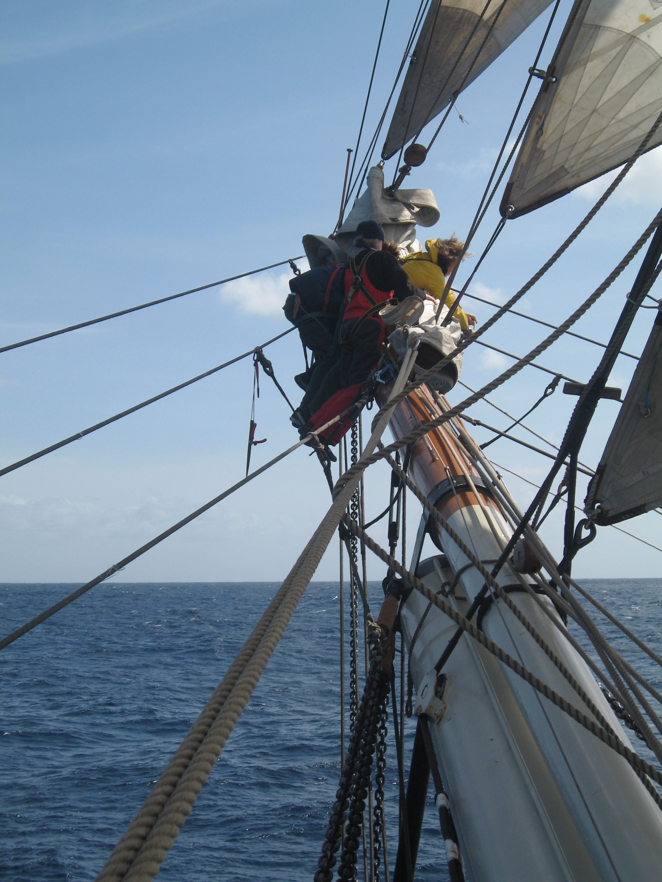
John Harland once published a paper in which he showed that a spritsail topsail would not set, while sailing on the wind, if the spritsail yard was braced around the axis of the bowsprit, nor if it was rotated in a horizontal plane. Armed with an early desktop computer, I sat down and figured out the geometry of the two yards (spritsail and spritsail topsail) that would allow the sail to set. Suffice to say that it was possible but would have been a bit like playing with a racing yacht's flat-cut spinnaker -- while coping with multiple lines, not just guy and sheet, two flexible pine yards (not one, stiff spinnaker pole) and highly unstable flax canvas, rather than "ripstop" nylon. Seeing the running rigging laid out as you have, I'm trying to wrap my head around the level of skills needed in each of a team of seamen, as they continually adjusted everything to keep that sail full and drawing. And all that while getting a wetting whenever the ship dipped her beakhead into a wave! You're doing a fabulous job of bringing it all to life. Trevor
- 321 replies
-
- 2
-

-
-
- Sovereign of the Seas
- Airfix
- (and 1 more)
-
Eileen, It has been a very long time since I read Derby's book cover-to-cover but I think he wrote that he could not find any lines plan for the ship. Maybe someone has since uncovered them! Trevor
-
At some times and in some places, shipwrights took the moulds into the woods and chose trees that suited particular pieces that they needed. A century and more after Endeavour, the schooner builders of Essex, Massachusetts sent sets of moulds to contractors in Delaware (the nearest remaining source of suitable white oak). The contractors chose the trees and had their workmen rough out the required pieces, which were transported north by sea. It was a whole different process from going to a local lumber yard and buying planks sawn to standard dimensions -- though plank and deals could be bought that way, if not sawn in the shipyard. Trevor
-
All of the contemporary textbooks described the structures of major warships and the similar, large merchantmen. I am confident that the Whitby colliers were different in at least details but I have no idea what the differences were. I don't even know whether there is any evidence that historians and archaeologists might examine. That being so, I will answer through the underlying principles of mid-18th Century English warship construction, even though that will be misleading somewhere. With that caveat: Bows were framed (in so far as the timbers that the planking was fastened to) with pieces that rose up and out from the centreline structure (of keel, keelson, stem etc.). Through to 1700 and a bit later, dockyard practice had a knighthead either side of the stem, with hawse pieces next. In a bluff-bowed collier, their outboard faces would have faced almost straight ahead. The foremost "square frame" (not a contemporary term) formed the outer edges of the beakhead bulkhead, in those vessels which had one. The cants framed the curve in between. However, they were nothing like the 19th-Century cant frames. In plan view, each of those look much like one-half of a square frame but set at an angle to the centreline. In contrast, the cants of 1700 (in plan view) reached out at right angles to the centreline. What made them different was that each piece was twisted around the axis of its own length (hence "cant", meaning twisted). That twist minimized the need for bevelling -- a process which turns very expensive compass timber into wood shavings. The English Royal dockyards adopted something closer to 19th-Century cants around 1715 but I expect the old way was maintained by distant shipwrights building smaller vessels. How long the Whitby shipwrights stuck with tried and true, I cannot say (and very likely nobody else can either). So much for the bows and the cants. The framing of sterns was quite different and maintained principles that made sense with 16th-Century square tucks. The principal pieces were the transoms, set transversely across the post. In warship construction, the highest (the wing transom) was at the level of the lower deck and the main wale. That ran nearly straight from starboard to larboard. With a round-tuck stern, the transoms below had to be increasingly curved and then angled. Low down in the hull, a transom would have needed trees that had grown with deeply-veed shapes and yet large thicknesses. As those were so rare as to be unobtainable, something else was needed. But higher up, where the hull was more broadly curved, the stern was framed with transverse transoms. So the short answer is that cants were not needed to frame the broad buttocks of a collier because those were not framed with timbers rising upwards from the keel but with transoms reaching (more or less) horizontally out from the post. At least, that would be so if warship-like framing structure was used. Cants were not needed below the lowest transom either, because what set the height of the lowest one was the narrowness of the run (need to provide a clean water flow to the rudder) and there the shape of the hull was not very far off parallel to the centreline, so that only moderate bevelling was needed. I don't want to be drawn into criticism of the work of any author who is not here to defend his efforts. I am certainly not going to pass judgement on a book that I have not read. However, to reconcile what I have just written with the framing diagram posted yesterday, I will note that my version would have the forward ends of the lower transoms extend to maybe Station 20, if they were to match the hull lines, whereas the framing diagram shows them reaching only to Station 26. Maybe Whitby shipwrights did use such short transoms and, if they did, they may have had to cant some of the timbers in the stern, rather than bevelling away half of the wood. But that would take me into the differences between warship and collier structures and, once again, I have no information on those. Trevor
-
It's the definitive source for Bluenose II and as close as we will get to the original schooner for things like hull shape and spar dimensions. Deck arrangements may be another matter, so worth checking MacAskill's photographs taken in the 1920s. "Yogi" Jensen's book was first published as a large-format, limited-edition folio at a price that (to me, as a student at the time) seemed astronomical. Fortunately, Nimbus' down-sized edition is very affordable, though my now-old eyes need a magnifier for some of the detail! Trevor
-
Damaged model, looking for the original details on it
Kenchington replied to Kevin Kenny's topic in Wood ship model kits
The model is a bit naive, maybe not quite to scale, and perhaps the details should not be taken too seriously. However, the double white bands on red funnels are distinctive and might give a clue. Unfortunately, the only line I can find that used that pattern was the Nelson Steam Navigation Co., which ran a service to Buenos Aires and maybe other South American ports. The only fleet list I can find for them shows the earliest ship as 1903, whereas the model is clearly of something much earlier. Peruvian is a much closer match. Her mainmast looks to have been proportioned and rigged for square yards (as in the model), though none were crossed when the photo was taken. Trevor -
I'll have to get back to that question this evening!
-
How ships' hulls were put together varied through time, from place to place and with the type of ship or shipwright. At one time, the Dutch had an approach in which they laid the bottom planks (with temporary fastenings) then put in the floors afterwards. The circa 1750 New England schooner that we partially excavated 40 years ago looked like the top timbers towards the stern had been added after the planking there, though I could not be sure. The main bend had futtocks treenailed together, though I would guess each timber was added to the growing structure, rather than the later approach of constructing a whole frame and then raising it into position. (As few other bends had the timbers fastened together, there was plenty of space to work an auger and swing a mallet around the main bend.) Warship construction in the major dockyards was a whole other business -- same basic concepts but far more exacting. Certainly, there was much use of (temporary) ribbands to tie the developing structure together until the wales, clamps and other permanent longitudinal elements were in place. There does seem to have been some conceptual link between designed bends and the fastening together of futtocks. English warship draughts of the 18th Century typically had only the bends for every third floor drawn out. On the actual ship, every third set of futtocks seems to have been fastened together, with "filling frames" (which may not have been a contemporary term) in between. In the dockyards, the intermediate futtocks were probably lofted by interpolating from the draughts. In contrast, small vessels like our schooner could have only the main bend and a few "mould frames" (again a modern term) fastened together. With those set up, and ribbands run around them, the shape of the other timbers may have been taken off the ribbands, rather than from a table of offsets -- though I doubt there is any contemporary evidence either way. But all of that concerns full-size construction. Unless you are documenting archaeological records in 3D or seeking to display a part-built vessel, there's not much need to replicate real-world complications. The classic Navy Board models show a very beautiful but very stylized version of 17th-Century ship structure! Trevor
-
I don't know what evidence there is for the frame of Endeavour specifically. Perhaps she had as many timbers in paired bends as that illustration indicates but in that era many another ship, built following English methods, had far fewer -- and not just high in the hull but from the first futtocks upwards. (The French, in contrast, had long-since adopted the 19th-Century approach for their warships, with the timbers in each bend fastened to one another. That gave more strength for the same amount of timber but at the cost of needing more weight in iron bolts.) Yes. But that was how boats and ships had been built for centuries and how the smallest wooden ones still are (unless they are glued together with modern chemicals). Into the mid-18th Century, the practice in English Royal dockyards was to get all of the floors bolted in place before any futtocks were added. At that point, there was no way to drive bolts between adjacent floors and futtocks, as they were far too close together. All connections between them were via the planking and footwaling. To anyone familiar with later ship structures, that looks weird. But it is how it was done. Of course many timbers curved in three dimensions. But there should not have been any cants in the after parts of such a ship. Cants were needed where the bow curved around towards the stem -- a curve in the design waterlines (not that the waterlines were drawn out in that era). There was no similar curvature in the stern, though there were sharper bends in the sections and what would now be the buttock lines. Canting the timbers would not have helped with framing those. Also: The attachment of the head of one timber to the heel of the next above is a bit of a vexed question. There certainly is evidence that some 18th-Century vessels were built with scarphing chocks, which were presumably fastened to the timbers above and below. Then there is mention in contemporary sources of eking pieces, used where the main timbers didn't quite curve enough, leaving a gap that could be filled by something that looked a lot like a scarphing chock but was an infill in low-cost construction rather than an expensive strengthening of a high-cost ship. And there were plenty of vessels built with the heel of one timber not even reaching to the head of the one below, let alone fastened to it. High-end warship construction produced relatively neat and regular structures but many a smaller vessel had framing that was decidedly irregular. The textbooks didn't show that, of course, but archaeological records of how real ships actually were do -- if the archaeologists took the time to study what was in front of them. Trevor
-
Sorry, Banyan but, as @ClipperFan has documented, clipper ships were initially a North American development, as were the (Baltimore) clippers which preceded them. The design concepts employed in the Baltimore clippers of circa 1810 had been discussed in Britain in the 1780s but it was US shipwrights who put them into practice in a major way and it is to the USA that we owe the term "clipper". It was also there that the clipper ship, the adaptation of clipper concepts to ship-sized hulls designed for sail, emerged -- even if their greatest designer, Donald McKay, was Nova Scotia-born and merely a "whitewashed Yankee". Scottish yards certainly contributed their own, later developments, such as the Aberdeen bow, but they were later. If you want to claim a British lead, it might be in the big steamers, which had quite other reasons for fine lines but did precede most of the Yankee clippers. Trevor
-
The transcontinental railroad was responsible for drawing the USA away from the sea. More exactly, opening the interior, with all of its opportunities for investment, was the draw, the railroad only the most prominent symbol. Sure, the War of Northern Aggression hastened the end but it would have come anyway. Shipping is inherently international and the British, paying less to their workers and hence with lower labour costs, could carry cargo to and from the USA more cheaply. Meanwhile, ships are their own advertisements, as they move from port to port. British shipyards, already more technically advanced as they had to cope without access to abundant timber, learnt from the Yankee clippers and produced more efficient (though slower) ships. Most of us who build models care about ships as artifacts but merchant ships are, first and foremost, commercial investments. They were and are mostly about profit margins and returns to capital -- for all that the people most closely involved got excited about speed or size, while the tea trade became the greatest sailing race there has ever been or is ever likely to be. Trevor
-
That is interesting. I think it is pointing but maybe grafting (and please don't ask me to define the difference!). Ashley illustrated multiple alternatives as his #3550 to #3565, with others scattered about on nearby pages of his tome. But why go to the extra trouble n the eye of a stay, instead of just serving? Did it produce a thicker cover for the rope within? Was it more stable, if part was worn away, where long lengths of service can come loose? Or maybe the ship's bo's'un was just showing off his skills and the pride in his ship! Trevor
-
I won't say that is wrong but I find it surprising -- where tarring of cordage is concerned. @wefalck: Can you point to your source for the use of coal tar in ship rigging, before the era of museum ships? There's scope for some confusion here. When laying up new rope in a ropewalk, both hemp and manila fibres were always tarred with pine tar -- the Stockholm (actually made more broadly in Sweden and probably elsewhere around the Baltic) product being preferred. So far as I am aware, that has never ceased, though few ropewalks produce hemp or manila material now. (Whether other fibres were tarred is more than I can say. I'll guess that cotton wasn't and isn't, but I don't know about coir. Modern synthetics are not.) That tarring of fibres when rope was/is made was/is standard. However, it would be unusual to apply extra tar to the outside of running rigging, once it was in place on board, aside from on servings covering eyes at ends and so forth. Surface tar along the length of running lines would gum up blocks, coat the crew in tar and generally create a mess. So we have standing rigging dark because of repeated application of tar to its surfaces, running rigging a lighter brown because its only tar is internal. Trevor
-
Joggling -- usually, though Smyth didn't include that term (or only with an unrelated meaning) and nor did Paasch, so I don't know whether it was in use before the 20th Century.
-
That one, I think I can answer: No, there were no deck lights in sailing ships. There is usually enough light, even on a moonless night, for men to work the rig and usually no call for anything more detailed (maintenance tasks or whatever) until daylight. When it was (and is) truly dark, seamen were expected to work by feel, knowing which line was belayed on which pin. As to lights for other ships to see and follow: My guess is that a rather ordinary lantern would be hoisted in the rigging, probably using a spare flag halliard or the like. That's how anchor lights were shown in more recent times. In the 1940s, it was claimed that U-Boat lookouts could find a convoy if one smoker could not resist the need to strike a match when on deck at night. (I don't know the truth of it but that was claimed at the time.) So a lantern with even a single candle could likely be seen from a distance, given reasonable weather. Trevor
-
Note also, in the posted images, that much (not all) of the rigging is in left-laid cord of some kind, whereas almost all rope is right-laid. That departure from full-size practice (I won't call it an "error") stands out like a sore thumb once you have the eye for it. Sure, any sailing-ship model is (today) a work of art rather than a miniature version of some full-size prototype. But, for myself, I don't see the artistry in misrepresenting the cordage. Trevor
-
Yes, if "common" means many ships had some lengths wormed but not parcelled and served. No, if you mean was much of the rigging done that way. It was one treatment among several alternatives and had specialized purposes at particular times. Trevor