


henrythestaffy
-
Posts
56 -
Joined
-
Last visited
Content Type
Profiles
Forums
Gallery
Events
Posts posted by henrythestaffy
-
-
Ian,
I have reduced the eagle to 4.5mb with 3D builder and it looks ok especially if the print was small. You need to open the STL file with 3dbuilder and then on the left top toolbar hit the import model button. Once that is done the other buttons on the toolbar will become selectable. Click on the model to select it. Then select Edit on the toolbar and then simplify on the far left of the toolbar. You should then see a reduction slider on the toolbar with the number of faces on the model. I slide the slider along about half way and reduced the faces quite a bit. It would be a case of experimenting with how far you want to go. Once you have decided where you want the slider to be hit the reduce faces button and depending on the power of your computer a little time later it will produce a result. Once you have what you want hit the save button and you are right to go with Tinkercad.
regards
Paul
- Ian_Grant, mtaylor and Glen McGuire
-
 2
2
-
 1
1
-
Ian,
I couldnt find that eagle on thingiverse. Do you have a link to it and I will see if I can make it a little smaller megabyte wise. Fusion 360 is also able to do it. I like your boat by the way. Last year I printed some rostra/rostrum and copper plated them. It was an experiment to see whether I could do it or not. I dont think I would bother again, the copper finish was a bit rough. The rostra turned out ok. I got the pictures from the Athlit study on academia. If you have a resin printer then the detail on the eagle will be ok even at a smaller size.
Regards
Paul
- mtaylor and Glen McGuire
-
2
-
Ian,
If you are using windows there is a program built in called 3d builder. If you import the eagle file into it there is an option to simplify which will reduce the size in megabytes. It might be an option to consider.
regards
paul
- Glen McGuire, mtaylor and Ian_Grant
-
3
-
Hi Patrick,
I saw your message regarding the cannons. Send me a pm and i try and help you out.
regards
paul
- Baker, scrubbyj427 and mtaylor
-
2
-
1
-
-
Have you thought about printing them?
- Keith Black and mtaylor
-
2
-
-
Tony,
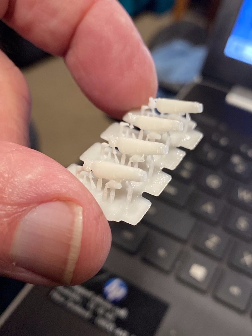
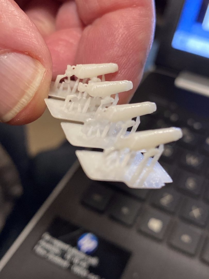
I am not sure what printing companies do but I can tell you that I take the picture that you posted above and import it into Fusion 360. I then create the model and scale it down after I am happy with the end result. The screenshots show the carronade after I have scaled it down from the size it would have been when originally created, which is the size of the drawing. I then save it as a mesh and import it into my slicer where the supports are installed. That can be a bit of trial and error. The last shots show the end result. As you can see they are very small. The detail is there except for the thin handles on the screw.
Paul
.png.543076c7995d268744e4d365dd845abd.png)
.png.0b1e615e6f8da082b4f7b059cd0bba00.png)
-
Ron,
When I use white resin the printer is set to 60 seconds for the first five layers and then 6 seconds for the rest. How did you arrive at 2.3 seconds for your print? Do you use the slider in the slicing software to simulate the print? It is a great tool for identifying "islands" which are the bane of all resin print jobs. Using default support positions will only go part of the way to a success print. I would also look at angling the parts so that the angled edge is printed first and gains a nice connection to the supports before the strain of a full edge is printed.
Paul
-
Tony, if you have a picture or pictures of the carronade you want I would be only too happy to create an STL file for you. The scale is unimportant at this stage as it can be adjusted prior to printing. You can also have a look on some of the sites that allow you to download files but you can not always find the one you want. This way if you have a particular gun in mind I can make exactly what you want.
Regards,
Paul
- tkay11, thibaultron and mtaylor
-
3
-
Kevin, I would look at why the fep sheet is winning the tug of war with the build plate by firstly checking the size of the connection from the supports to the model. It appears they are not strong enough to handle the pulling forces. The strength of the support is only as good as the point it connects to the model in most cases. Maybe alter it to make the connection a little deeper and wider. Second, as suggested above, tilt your model in a way that creates a lesser amount of connection to the fep. Say around 30 to 40 degrees. Printing a large surface parallel to the build plate is not a very good habit to get into. When a model is tilted you can get away with using finer supports. If these steps dont help then i would look at replacing the fep sheet as it seems to have too strong a hold on the model as it prints. Good luck.
Paul
- thibaultron and mtaylor
-
1
-
1
-
-
Steven, if you did want them printed what size and how many holes would you need?
- mtaylor and Keith Black
-
2
-
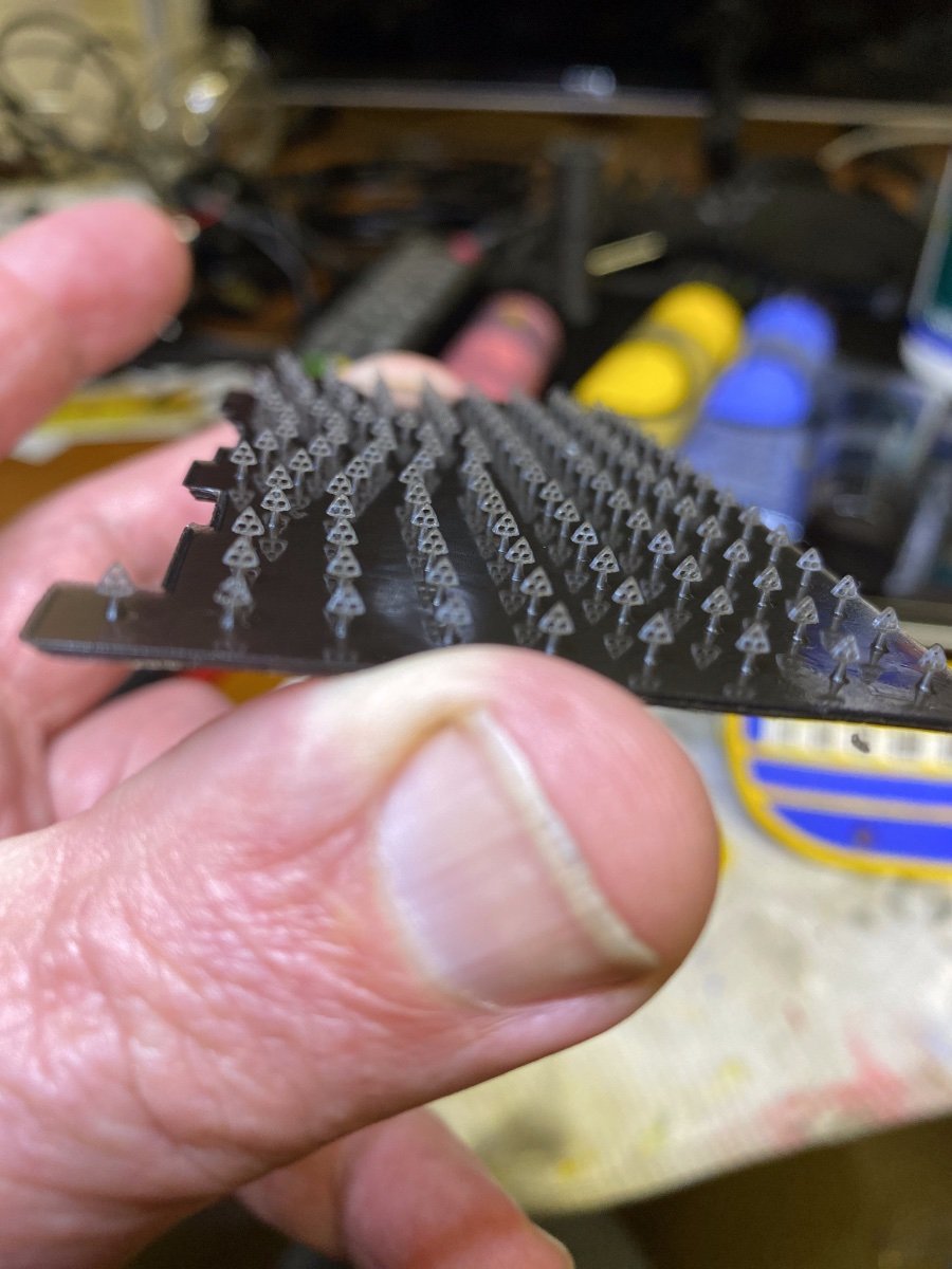
Steven i have two lots of deadeyes totalling about 250 so far. The sides are a bit straighter than the previous ones but not completely straight. I found they didnt print very well unless i added a bit of meat around the holes. I have made the ends a lot tighter as you wanted as well. I reckon if i print this amount again it should give you enough to complete your task . I should have them finished on monday for you.
regards
Paul

- Keith Black, liteflight, Baker and 10 others
-
9
-
 4
4
-
Steven, let me know if you want me to print some for you.
Paul
- mtaylor and Keith Black
-
2
-
I like your figures. Did you design them yourself?
- thibaultron and mtaylor
-
2
-
-
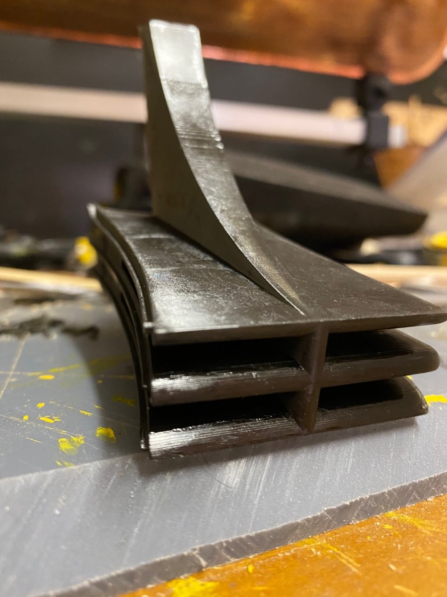
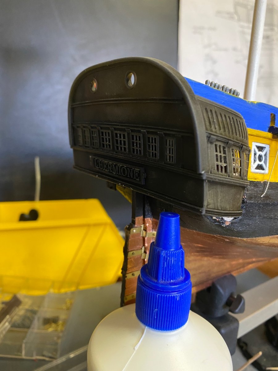
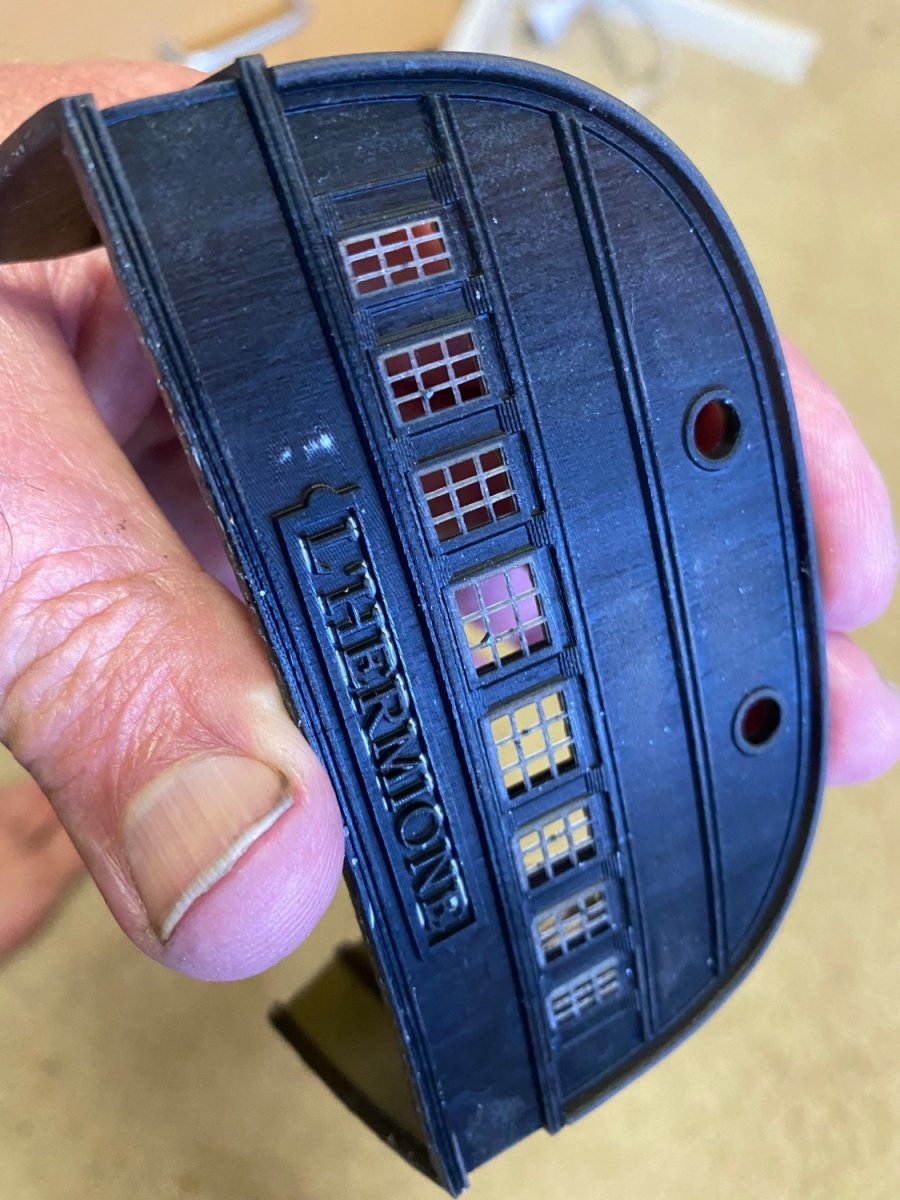
I had a look at your Victory log and I was very impressed. Especially with the way your made the arms and other "organic" shapes. This is an area I have trouble with and it gives me hope that there is a way to do it properly. My original wooden stern had the problem your mention with the unsupported top part starting to straighten and it drove me mad to look at it. It frustrated me so much I just pulled it off and forced myself to do it again with resin. I noticed you made the letters seperate to make it cleaner with painting which I like the idea of. My stern is all one piece and I can see that painting the letters is going to cause me some concern. Have you ever considered using resin to adhere your parts together instead of glue? It works quite well and is very strong. I was thinking of printing some plugs similar to the ones that screw into plaster walls and screwing them into the ship at points where the stern will touch the model. Then use resin to adhere the two parts together which should create a strong bond. Either that or a resin rod through the model from quarter to quarter and then attaching the stern to that.
-
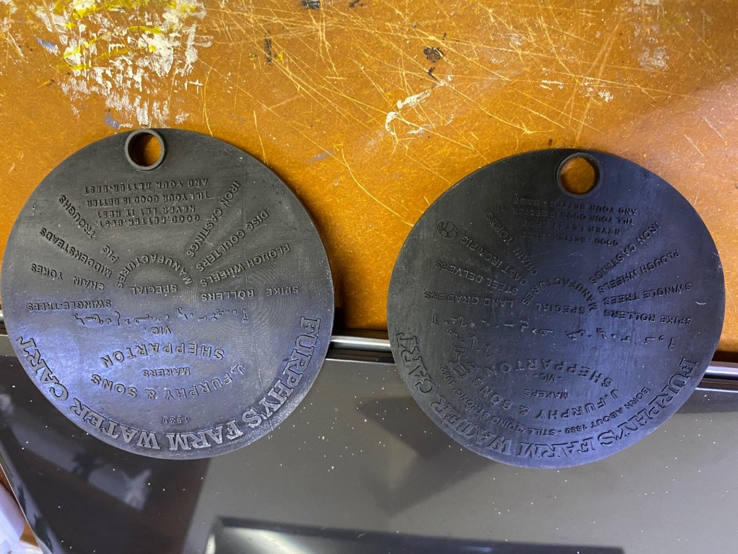
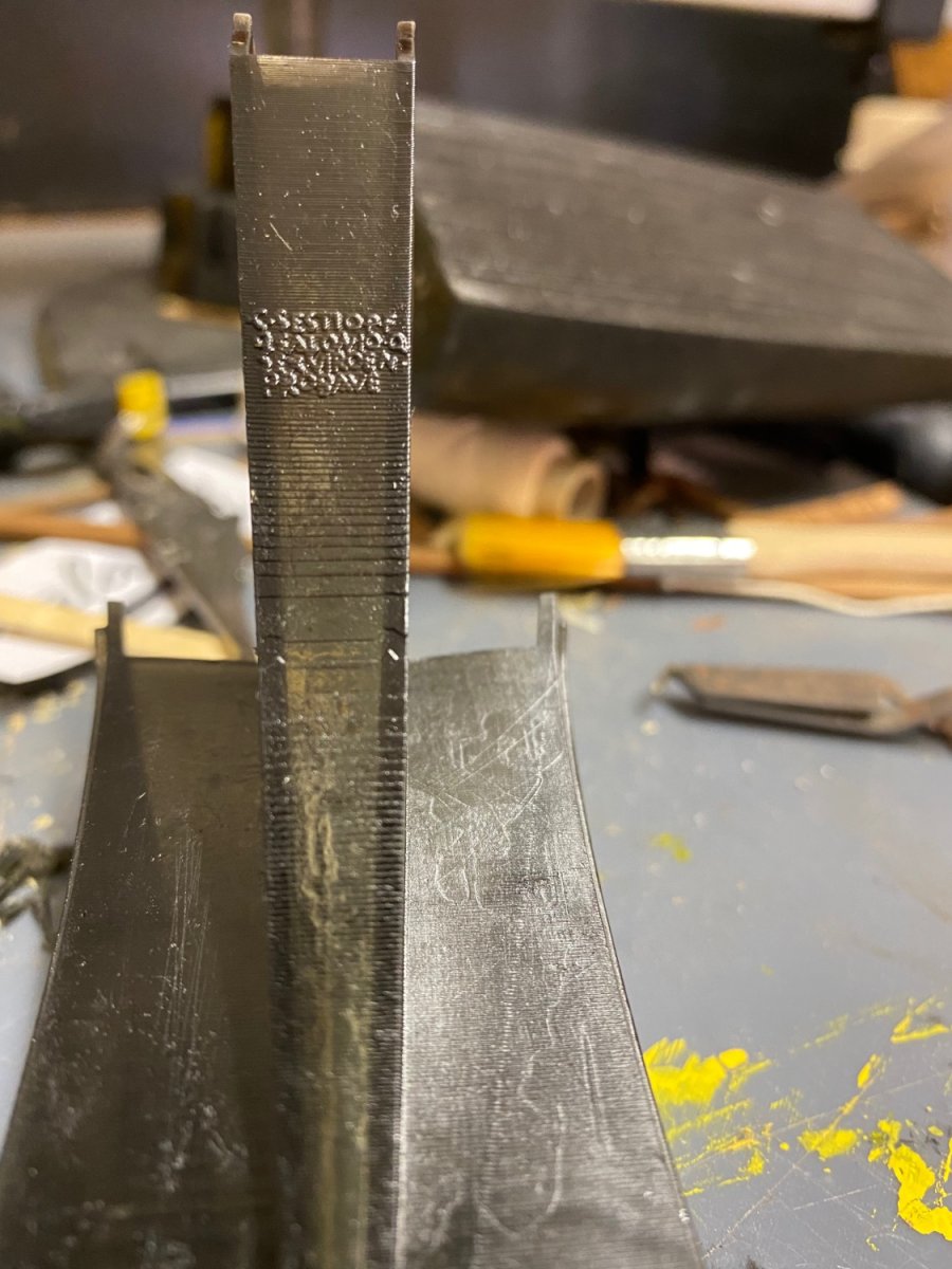
These would be recognisable to most Aussies. I am not sure if there are any overseas, though i believe there are a couple in Antarctica. Created with fusion and printed with resin.
- Keith Black, bruce d and thibaultron
-
3
-
-
You are a very talented man Steven
- Keith Black, mtaylor, Louie da fly and 1 other
-
3
-
1
-
Dave,
I can print as many barrels as you need or if you have access to a printer near home I can send you an STL file. All I need from you is a picture or drawing of the cannons.
Paul
- Dave_E, mtaylor and Keith Black
-
2
-
1
-
-
Thanks Ian,
Let me know if you want some cannons for the Soliel in a bigger scale.
- thibaultron and mtaylor
-
2
.png.6d3db5fa47163033dc556d3884df9200.png)


Redoing Oseberg
in CAD and 3D Modelling/Drafting Plans with Software
Posted
I am not sure if i can be of any help but i use fusion 360 and have an interest in oseberg. My services are at your command if you wish.
paul