Chuck
-
Posts
9,703 -
Joined
-
Last visited
Content Type
Profiles
Forums
Gallery
Events
Everything posted by Chuck
-
 Thanks George....No kit but definitely some other parts....see this post in the build log. But I havent ruled it out entirely. I Never say never. http://modelshipworld.com/index.php/topic/8131-hm-cutter-cheerful-1806-148-scale-by-chuck/?p=244654
- 1,051 replies
-
- 3
-

-
- cheerful
- Syren Ship Model Company
- (and 1 more)
-
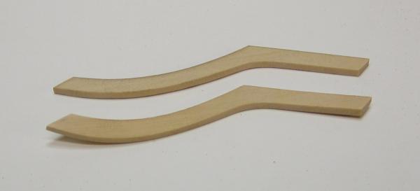
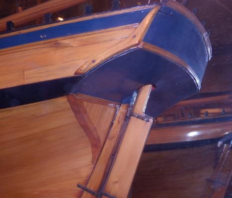
I was able to shape the fashion pieces today. They are will be in one piece with the boom crutch added separately later. The boom crutches wont be added until the cap rail is added way down the road. For now I just left them extra long so I can file them back to where I want them. You can see in the photo how the bottom fashion piece was bent using heat.....no water or soaking. The top one is the flat 1/16" thick piece which has not been bent yet. Once these were glued on the model, the second layer of the wales (two strakes) were added and painted. I still have to paint them on the other side. After thats done I will treenail above the wales. That will be easier to do before I add the fancy molding along the sides of the hull per the plan. Notice how the fashion piece covers the end grain of the planks on the stern transom. When the stern is all done there shouldnt be any end-grain exposed for any of the planking. The fashion piece and square tuck protect them from the elements.

- 1,051 replies
-
- 34
-
-
- cheerful
- Syren Ship Model Company
- (and 1 more)
-
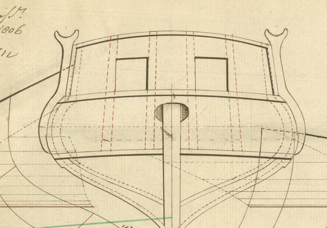
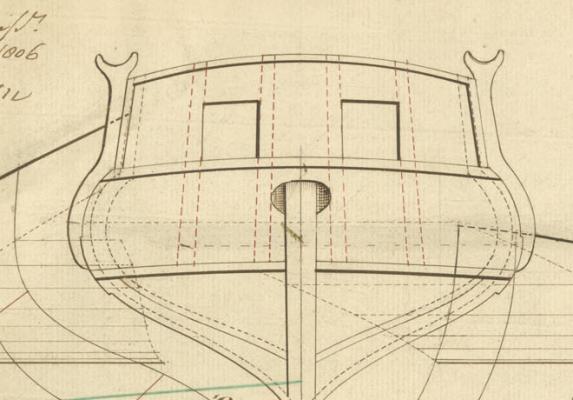
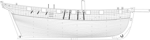
These were actually either centered as you have shown or there were two P & S. Here is a detail from the Cheerful draft. They were actually angled to match the angle of the boom rather than facing straight ahead. They were an extension above the fashion pieces.
-
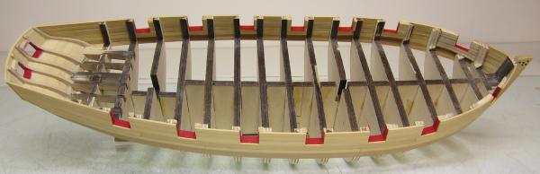
That look like a very well constructed skeleton. Its looking faired and true. Well done!!
-
Thats not entirely true....if everyone thought I was nuts or off-base I wouldnt have. Based on the even mix of opinions though, I feel comfortable that folks wont say "what was he thinking". So black and red it is.....the comments are a huge help actually. I am hopefully going to get the fashion pieces made and installed today and then the final layer of wales. Chuck
- 1,051 replies
-
- 6
-
-
- cheerful
- Syren Ship Model Company
- (and 1 more)
-
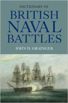
Dictionary of British Naval Battles By John D. Grainger Woodbridge, Suffolk: The Boydell Press, 2012 6-1/2” x 9-1/2”, hardcover, xiv + 588 pages Maps, glossary, bibliography, index. $90.00 ISBN: 9781843837046 John D. Grainger has presented readers with a thorough and accessible reference source on British naval encounters in his book, Dictionary of British Naval Battles. Focusing on British naval encounters from the Middle Ages through modern day, Grainger offers a new resource for naval historians and those with a casual interest in naval warfare alike. Addressing not only on the major battles of British naval history but on small naval encounters as well, Grainger offers an interpretation of Britain’s naval prowess rarely covered in other accounts. In doing so, Grainger presents the development of a diverse and influential naval force that became the dominant power on the sea throughout much of history. Grainger’s central objective is to demonstrate the breadth and multiplicity of British naval power throughout British history. Highlighting the widespread influence of Britain across the globe and its use of naval power to obtain this supremacy, Grainger aptly portrays the British navy as an active and disseminated entity almost continuously utilized. Using largely secondary sources, Grainger discusses each naval encounter in a clear and concise manor, detailing the vessels involved and their outfits, in addition to discussing the details of each event. Grainger organizes his work by naval vessel and individual battle, allowing him to discuss even small naval encounters largely overlooked in many British naval histories. Grainger begins his work discussing the meaning of the expressions “British”, “naval” and “dictionary”, effectively describing his definitions for the words as they pertain to the topics included in his work. Maintaining that “British” must include any navy under British rule, in one volume, Grainger effectively is able to discuss naval encounters ranging from the northern Irish attack on the Hebrides in 580 AD to Britain’s naval endeavors in the Persian Gulf. Focusing on each naval battle in turn, Grainger maintains a level of detail in each entry that surpasses many other works of the same nature. Grainger has produced detailed and well-crafted entries on a wide range of British naval topics, spanning from the medieval period to modern day. While his research is comprehensive, his scope remains very large, which at times can seem overwhelming. Though his general outline takes a logical and systematic approach, the wide range of topics covered has the potential to lose a reader. At times, the chronology of events is lost due to the alphabetical organization of the work, taking away from a more liminal understanding of Britain’s naval history. Despite this, Grainger clearly addresses his organizational technique in his introduction, and provides readers with additional references at the end of each entry for those interested in learning more about specific topics. Overall, Grainger has produced a well-researched and skillfully written addition to the canon of British naval history. Grainger has developed a valuable source of knowledge on British naval events, effectively producing an important reference source on British vessels, battles, and naval warfare. Caitlin Zant East Carolina University
-
- 4
-
-
Well done...It is looking really good. Chuck
-
Natural is the safe way to go. I think I am a bit more adventurous than that. So I will go with the Surly color scheme. It will be interesting to see a few more with different paint schemes should any of you decide to build her as well. Thats the fun part of this hobby. But who knows, I could change my mind tomorrow.
- 1,051 replies
-
- 11
-
-
- cheerful
- Syren Ship Model Company
- (and 1 more)
-
That looks very good Rusty. As fine as any planking job that I have seen. I applaud your willingness to try the proper planking techniques of spiling and such. Its different than just force bending and may take more time but once you start, its something you will just continue to do. Well done!!! Chuck
-
I am actually leaning towards the Surly paint scheme. Black caprail and black sheer strip, with red bulwarks and red counter. But that can change, This is always a struggle for me to decide. Chuck
- 1,051 replies
-
- 6
-
-
- cheerful
- Syren Ship Model Company
- (and 1 more)
-
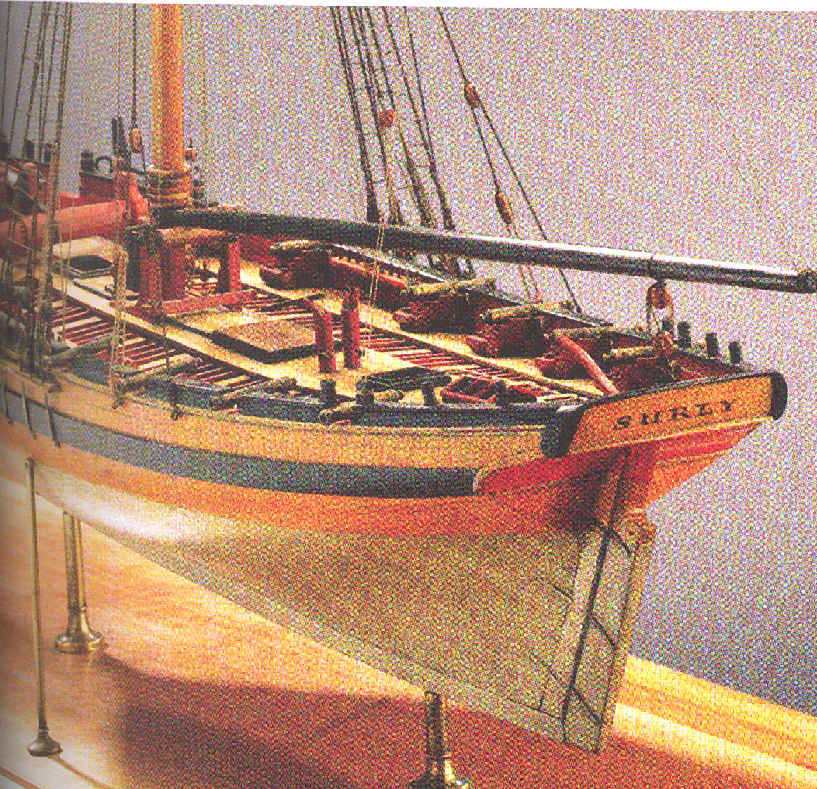
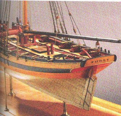
Almost forgot.....looking for some second opinions. I am thinking about painting the lower counter and leaving the transom natural. Like the Surly contemporary model. What do you think? Maybe blue....but not this bright. Is it too much? Maybe leave it all natural back there? You will also note how the Surly had the bulwarks cut down which is why the transom is a funky shape. This was done during a refit long after the Cheerful was already gone. Cheerful didnt last too long. Maybe I will switch and call her the Surly....I am not feeling too cheerful today.. Chuck
- 1,051 replies
-
- 12
-
-
- cheerful
- Syren Ship Model Company
- (and 1 more)
-
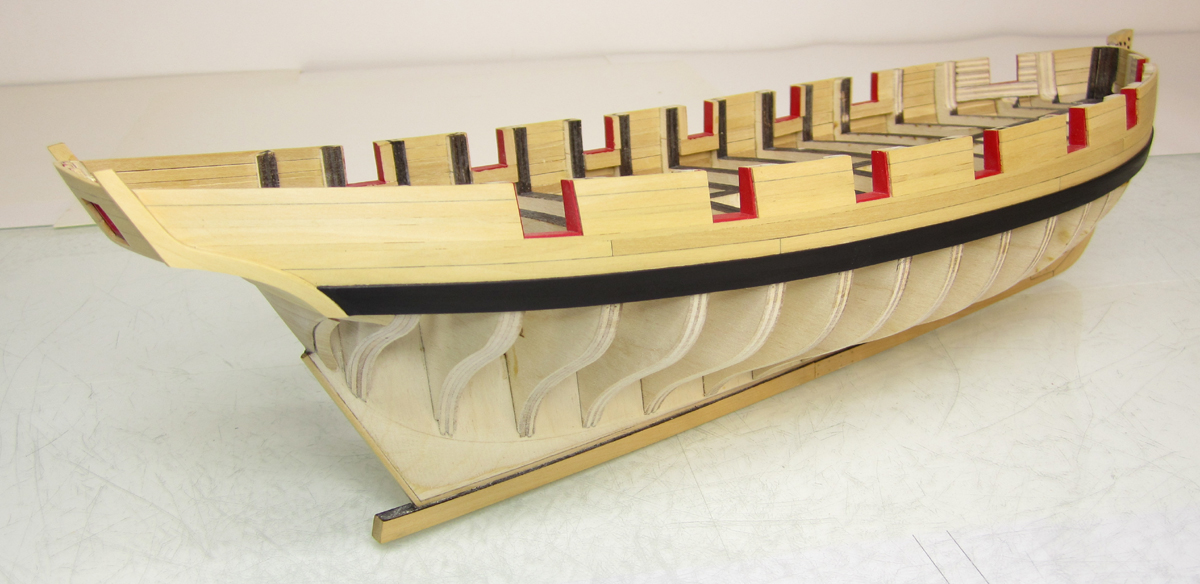
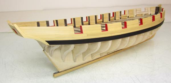
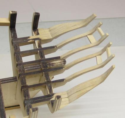
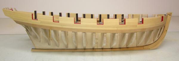
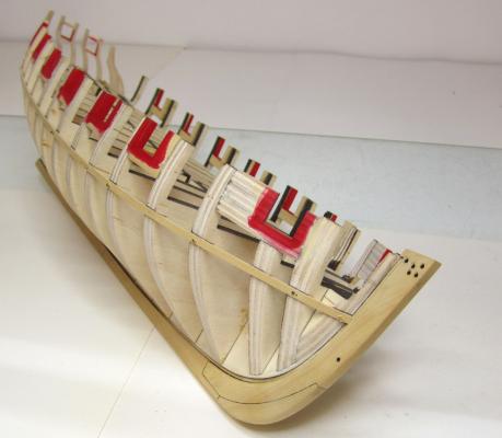
Got the counter and the transom planked. You may notice that I thinned down the outside stern frames considerably before planking the stern. The first photo shows how thick they were before it was planked. After the sides of the hull were planked the outside stern frames were strong enough to handle the thinning down. It makes the model more historically correct. The inboard side of the stern and counter will not be planked so I wanted to make sure it looked as authentic as possible. That of course means that I must really clean up the inboard side between the stern frames carefully to prepare it for painting. I will fill any cracks and sand it smooth and do lots of surface prep. Now I can have some fun. Its time to put the fashion pieces on and the wales and fancy trim. This is the step that will make it really come together. Chuck

- 1,051 replies
-
- 35
-
-
- cheerful
- Syren Ship Model Company
- (and 1 more)
-
It would be tough to get pieces large enough if you are building in a larger scale. But I have used hard maple from Home Depot or lowes that was 1/4" thick. It worked fantastic. The stuff is rock hard though so be prepared to sand and sand....its tough to cut as well as the blades will get dull quickly. Chuck
-
Funny....Yes, I introduced my son to binge watching the X Files from start to finish on Netflix. He bought me that poster as a thank you. It was a blast watching it with him. Big Sci-fi buff. Chuck
- 1,051 replies
-
- 3
-
-
- cheerful
- Syren Ship Model Company
- (and 1 more)
-
Thats the laser char....I didnt bother sanding it....it will all be removed when I take down the bulwarks later. The ply burns a bit and teh char is more evident. Chuck
- 1,051 replies
-
- 3
-
-
- cheerful
- Syren Ship Model Company
- (and 1 more)
-
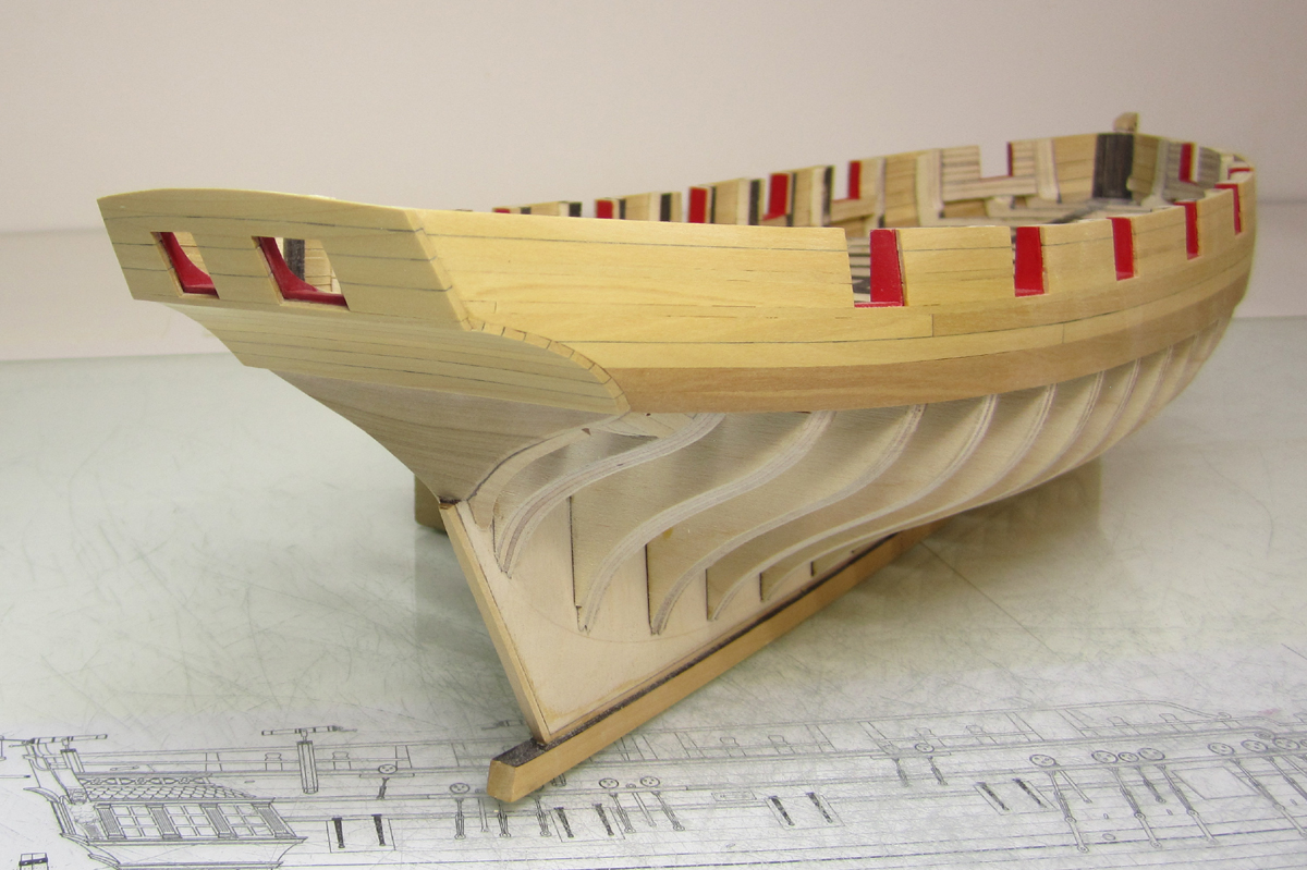
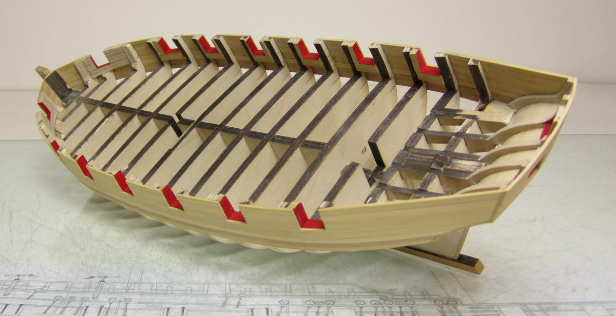
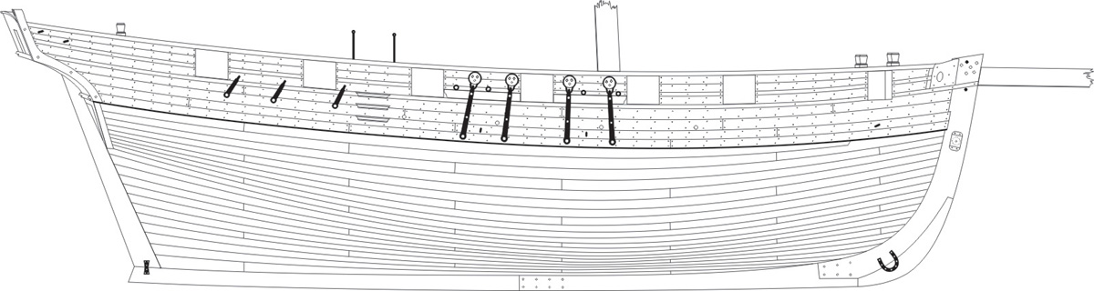
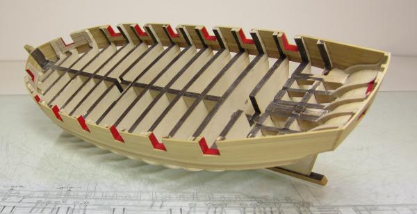
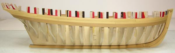
The planking above the wales is basically completed. Just a few more planks to add on the port side as you can see. I didnt bother simulating the caulking between the seams where it wont show. So it looks a bit weird now. But once the molding and second layer of the wales is added it will look fine. You can only see a few places with a crisp line for the seams. This was done by running a number two pencil down one plank edge. If I did this on both plank edges it would have been too pronounced for my tastes. I will plank the transom and counter next at the stern. Its an interesting detail that in case of a cutter like this you dont plank the stern counter first. The transom and counter are planked after the sides of the hull. The exposed end-grain of the counter planking and transom planking will be protected from the elements and rot by the fashion pieces. You can see them in the profile drawing. So you will not see any of the end grain from the planking. The frame for the square tuck also does this for the end grain of the planks. Its an interesting feature and I almost forgot NOT to plank the counter first. It is something I am so accustomed to doing. Before I plank the stern transom and counter I have some shaping of the outer stern frames to do. I will post pictures of this as well because its an important feature to keeping the finished model looking accurate. So far its coming together quite well without any real issues. Its a fun build so far. You can start to see the final shape of the cutter come to life as the planking progresses. I know the bulwarks look thick at this point but they will actually be thinned down quite a bit soon. The outboard and inboard planking at the sheer was actually just 1 1/2" thick....once its planked inboard and out the final width will be just 1/8 - 5/32" thick at the most. Closer to 1/8" thick I hope.
- 1,051 replies
-
- 33
-
-
- cheerful
- Syren Ship Model Company
- (and 1 more)
-
Nautical Research Guild Winter Issue is in the mail. Become a member and get it delivered to your front door every 3 months. Here are some highlights including the table of contents. EDITORIAL . . . . . . . . . . . . . . . . . . . . . . . . . . . . . . . . . . . . . . . . . . . 242 The Weedon Island Dugout: A 1,100 year-old Saltwater Canoe by Irwin Schuster . . . . . . . . . . . . . . . . . . . . . . . . . . . . . . . . . . . . . . .243 The Blockade Runner Condor by Jeneva Wright . . . . . . . . . . . . . . . . . . . . . . . . . . . . . . . . . . . . . . . .251 Scratch Building a United States Navy Anchor Hoy of circa 1819 by Don Meadows . . . . . . . . . . . . . . . . . . . . . . . . . . . . . . . . . . . . . . .271 Trash to Treasure—A Restoration Project by Bill Mitchell . . . . . . . . . . . . . . . . . . . . . . . . . . . . . . . . . . . . . . . . . 281 HMS Ardent: A King’s Ship, But Which King? by Ron Neilson . . . . . . . . . . . . . . . . . . . . . . . . . . . . . . . . . . . . . . . . .289 A Traditional 10-foot Wooden Dinghy Model by Byron Rosenbaum . . . . . . . . . . . . . . . . . . . . . . . . . . . . . . . . . . . .305 SHOP NOTES Simulated Deadeyes for Mini-Models by Irwin Schuster . . . . . . . . . . . . . . . . . . . . . . . . . . . . . . . . . . . . . . . . 311 A Bonding Jig for Acrylic by Irwin Schuster . . . . . . . . . . . . . . . . . . . . . . . . . . . . . . . . . . . . . . . . 311 MODELERS’ REVIEWS Orange Hobby HMS Victorious (1966) Kit by Mark Myers . . . . . . . . . . . . . . . . . . . . . . . . . . . . . . . . . . . . . . . . . . 313 Letters to the Editor. . . . . . . . . . . . . . . . . . . . . . . . . . . . . . . . . . . . . . . . . .315 BOOK REVIEWS . . . . . . . . . . . . . . . . . . . . . . . . . . . . . . . . . . . . . . . . . . ..315 ADVERTISER INDEX . . . . . . . . . . . . . . . . . . . . . . . . . . . . . . . . . . . . . . . . 316 Click here to read one of the articles.... Read this months Editorial by Paul Fontenoy For more info on the Journal and the NRG please visit the website.

-
- 5
-
-
I will move it to the correct forum....
-
Thanks...Yes indeed I do But it all gets done eventually. I really like coffee. Chuck
- 1,051 replies
-
- 6
-
-
- cheerful
- Syren Ship Model Company
- (and 1 more)
-
Very nice....With a little luck I will be back at my Winnie in a month or so!! I cant let you catch up to me
-
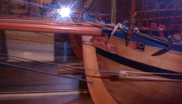
On the Hawke...that isnt the bobstay. That is actually the Jib outhaul. But I agree with you on Frank on the bobstay. But as with the Hawke and the model used for teh Peterson book, some contemporary models dont show it. In fact...many of the photos Michael showed above are not actually the bobstay. They are also the jib outhaul attached to the traveler ring. Then it reeves through the end of the bowsprit and runs to a sheave along the stem. Or in some cases a simple block setup Go figure.
- 17 replies
-
- 1
-
-
- Sherbourne
- bobstay
- (and 2 more)
-
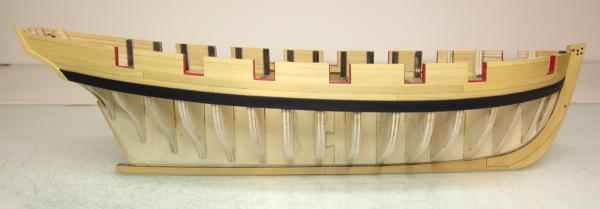
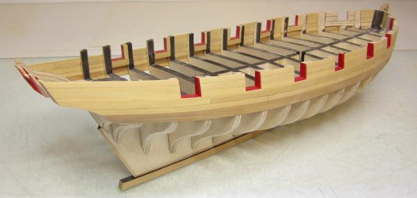
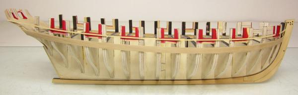
Thanks guys Rusty it will be basically the same. Except in this case the original planking expansion did show one drop plank at the bow. I am basically replicating that draft exactly. So I will include that drop plank and then divide the bottom of the hull into belts. But only two this time. Then I will line off the hull before moving forward with the planking. Heres what the hull looks like after those two planks were added between the molding and the wales. I only darkened the seams where it will eventually be noticed. This helps if I need to tweak the placement of the second layer for the wales and molding. Without the seams darker its easier to move the second layer without folks noticing. You will notice the darker wales. This was just a sheet of boxwood I had that was noticeable darker. I figured what the heck, I might as well use it for the wales. Its going to be painted anyway. It also helps me visualize the run of the wales as I plank above them.
- 1,051 replies
-
- 20
-
-
- cheerful
- Syren Ship Model Company
- (and 1 more)
-
Only the wales.....its a single plank on bulkhead, But rather than use a thicker plank for the wales and molding, those are done in two layers.
-
Unfortunately you cant base everything 100% from Peterson's book. It is based only on one model. There are countless examples of a cutter from many different time periods rigged with a bobstay. The Surly is rigged with one as the image shows above. Earlier examples had the bobstay go through a hole in the stem. Later they had an iron fitting with an eyebolt attached to the front of the stem so they didnt have to drill through it. This made it prone to rot. The cheerful in the Rogers collection has one. Chuck
- 17 replies
-
- 1
-
-
- Sherbourne
- bobstay
- (and 2 more)
-
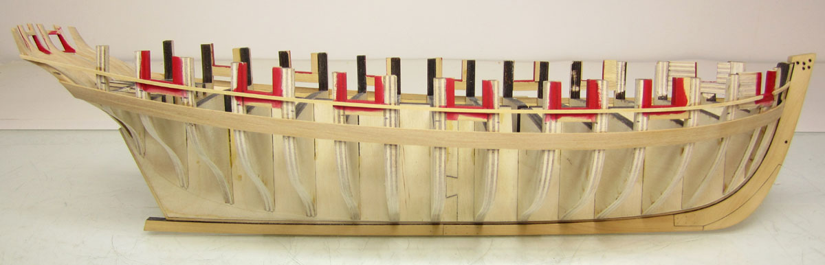
I started the planking today. This always begins with placing battens on the hull. The top of the batten represents the bottom edge of the wales. I really spent a lot of time on these because it will establish the run of all of the planks on the hull. It was added to both sides so I can check it from every conceivable angle. Once I was satisfied I planked the wales with two strips. This will be the first layer. After I plank the hull from here up to the sheer, I will come back and add the final layer. Its a hold over from my time building kits. I like the idea of being able to make small adjustments with the run of the wales on the final layer. Since it will be painted black and this isnt the final layer it laid down in one long strip rather than in 25 foot long pieces. Now on most ships you can just start planking from the wales up...the run of the wales determines the run of the planking above it to the sheer. Mostly anyway. In this case however it isnt true. It is again one of the reasons I chose the Cheerful. Its not difficult work at all but requires careful planning. If you examine the plan for the cheerful you will see the run of two moldings just under and through the gunports. I was fortunate to have the original draft for teh planking expansion and my model will follow it exactly. The same number of strakes and their run are precisely copied from it. The space between this molding and the wales is not consistent. So I decided to add the 1/16" strip first which for the most part runs right under the ports, leaving a 1/64" rabbet along the bottom of each port. Then I divided up that space between the molding strip and the wales equally so I can taper these two strakes that will fit between them. You may be able to see my tick marks defining the space and strakes on each bulkhead. The molding strip is just the first layer also....Once its all done I will come back and add the final layer after scraping the fancy profile into it. Once again, having a little wiggle room to adjust teh run of the molding later is a huge plus. Then its just a matter of finishing the planking and other molding strip as I work my way up to the sheer. Chuck

- 1,051 replies
-
- 29
-
-
- cheerful
- Syren Ship Model Company
- (and 1 more)