Chuck
-
Posts
9,703 -
Joined
-
Last visited
Content Type
Profiles
Forums
Gallery
Events
Everything posted by Chuck
-
 Measure the scale bar on teh plan as most likely the plan was printed too small. The sections of the scale bar should be 1/4" long. It is so weird that they could screw up such a small kit having so few pieces. If the plan is OK and the parts are too big...hopefully you can adjust them by sanding the laser char off and making them the correct size. Chuck
- 55 replies
-
- 1
-

-
- 18th century longboat
- model shipways
- (and 1 more)
-
Beautiful!! Well done and the perfect size.
-
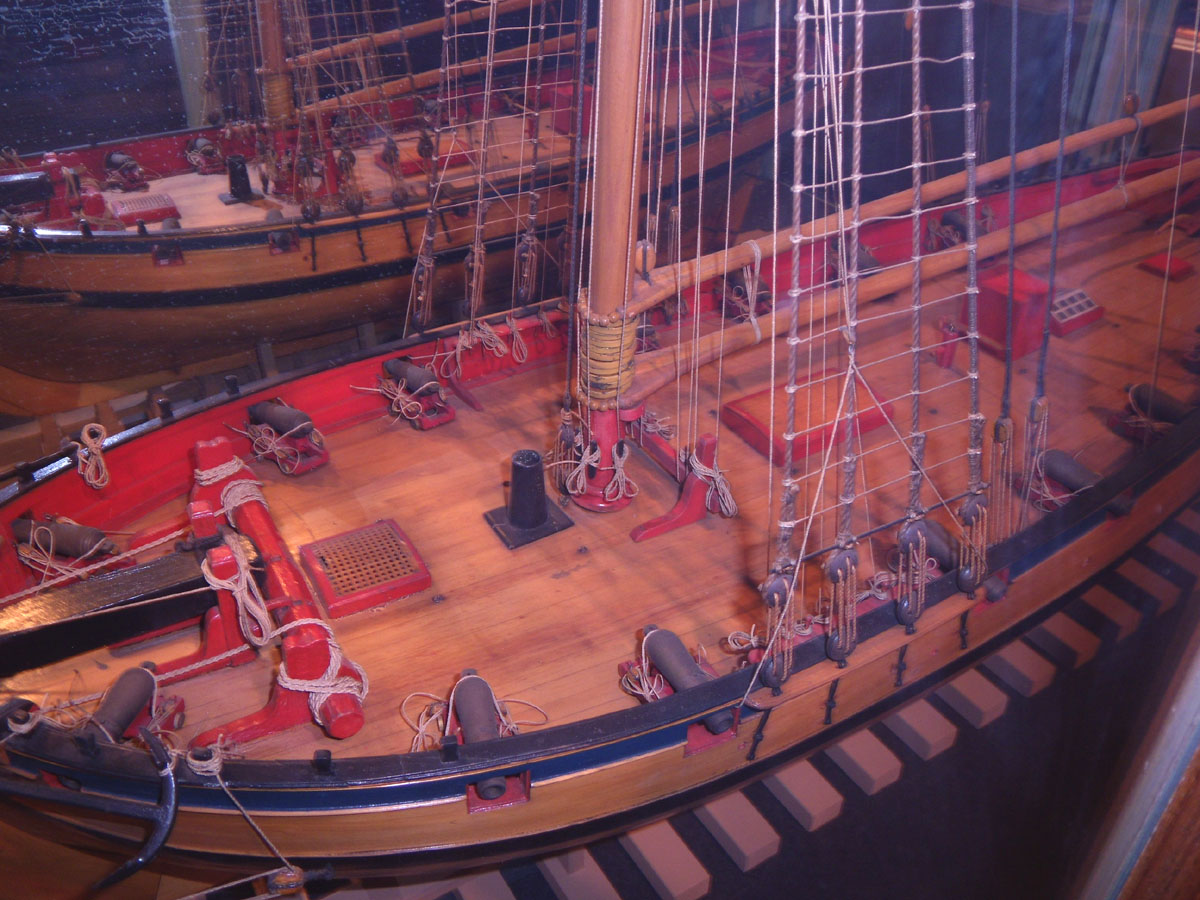
Yes I agree with that...Half of its original width at the butt end. If it was thinner it would defeat the purpose of doing it that way. Primary sources are key including contemporary models. Its like the outboard planking around the ports... You rarely see it illustrated and talked about in books like Robert's or Mondfeld. But the methods are shown on contemporary drafts and texts and building contracts.... Like this detail outboard of the planking on top of and below the ports...you will never find it in Monfeld If you want raise the level of accuracy always try and get your hands on some primary sources.
-
Uh...not exactly From the same Goodwin book. It just wasnt illustrated. There is a whole section about the margin plank. The bottom drawing does show and list the margin plank but only the later nibbed variety. In actual practice this is how it was done back then. Here is an excerpt... " Parallel to the ships side and fayed to the waterway was a strake of planking known as the margin plank. The function of this was to prevent the normal straight deck planking from being tapered to a fine angle where it met the curvature of the ship's side at the fore and after ends. The margin plank was thus fashioned to receive the butts of those planks. It was stipulated that no plank was to be 'joggled" into the margin plank unless the length of its tapered edge was more than twice the width of the plank, and that the plank was only to be tapered or "snaped" to half its width at the butt end. The margin plank was the same thickness as the deck plank, but one and a half times as wide." This describes very late 18th century nibbing practice and early 19th. Prior to this, 1760's... rather than nib into the margin or waterway, they hooked the planks as shown in the contemporary models I posted which is as primary a source as you can get. The "hooked" planks instead sitting against and alongside the margin. They were also tapered and curved a bit at the fore and aft ends of the deck. This was done to keep the margin/waterway in tact among other reasons. The rules are out there..you just have to find them. Primary sources are the key. Secondary sources are all over the map with omissions and simplifications. Goodwin is an excellent source. Sadly Mondfeld is not held in the same way. Although I wish that it was indeed the way Roberts described..it would be much less hassle. To further complicate about actual deck planking practices from this time, other details are rarely illustrated but can be seen on contemporary models and described in primary texts. Those include the anchor style deck planks that sometimes ran along the bulwarks a couple of strakes inboard. Also from Goodwin.. " fitted two strakes of either top and butt or anchor stock 4ft from each side of the ship. The function of this was to resist any athwartships compression that occurred when the vessel was in heavy seas." One other rule....not often illustrated "no plank butts between the hatches and comings" A single length of deck plank was laid between the hatches with no need for butt seams even though this may have disrupted the normal three or four butt shift pattern. Depending on how historically accurate you want to get with the details,there are many rules like this and no one source really contains them all. But once again, luckily for us... most have been compiled in the fully framed series. Makes our lives much easier. This secondary source contains more of these rules in one place than any other. So unless you want to poke around and gather the many many other resources...both primary and secondary for these individual nuggets, I highly recommend the series.
-
I am going to paint my windlass red... just in case you are wondering. It would be easier to do before you assemble the individual completed sections of the drum. It looks like a promising start so far. Yes it was designed so that you could use the laser char to gauge when you are done beveling. It should all be gone from the edge when you are done...but just barely. I also icluded an extra face or two for some segments. But let me know if you need additional for boo-boos. I just used an emery board that was 1 inch wide with a medium grit to create the bevel while holding the faces between two fingers. Basically eye-balling it. Your method seems much more accurate. But if you do plan on painting it red...you can fill the few cracks and seems that may be there. Chuck

-
Cutter Cheerful 1806 by Maury S - 1:48 - POB
Chuck replied to Maury S's topic in - Build logs for subjects built 1801 - 1850
That looks so familiar....looks great. -
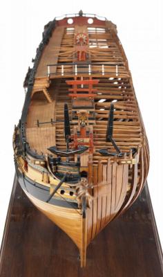
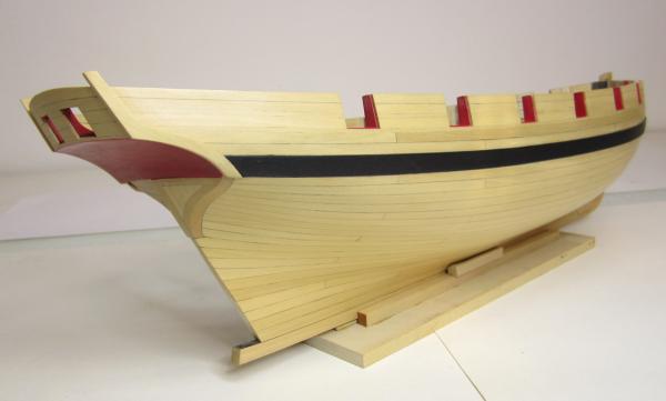
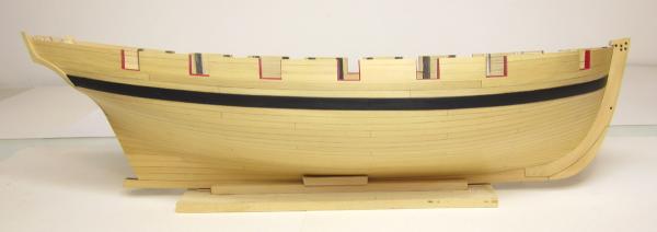
Yes indeed that is the Model shipways solid hull kit, Essex....I think we have one in the Gallery....Here are some comparison images...just the paint colors are different. From the early 60's or 70's and possibly even the early 80's. It was made in two scales...1/8" scale was the first version and that could be as old as the 50's but this is clearly the 5/32" version. It may have been built later because I see some of the earmarks spelled out in Jim Roberts book on building the kit. Which buy todays standards was just a min practicum on building the kit. Many of the details on your old model are dead ringers for what he wrote about. The figurehead is also a dead give away...you see, the metal casting...lead at the time was very soft. The hatchet or axe the Indian was supposed to hold in his hand was always bent or broken and had to be replaced. It is why it may appear slightly different on models that were completed. But the body is a perfect copy with its flowing cape. I may even have one laying around the shop. Comparison
- 16 replies
-
- 3
-
-
- 38-gun
- Artois-class fifth rate
- (and 2 more)
-
Discussions are good I think Jim simplified it for model builders Keep in mind the use of the term Margin plank in my instructions...it is yet another simplification. Essentially the waterway at this time was a very wide plank that had a raised lip on its outer edge....one piece To simply it and model it in two pieces, I refer to it in the Confederacy instructions as two separate parts....the waterway being a thin rounded piece placed over what I describe as "the margin plank". The thin piece becoming the raised lip. But essentially they were one piece and properly identified as the waterway...one piece.... I hope that makes sense. I have never seen a rounded bow with deck planking that wasnt hook scarfed or later nibbed into this waterway because it would create really thin pointy deck planks which are prone to rot very quickly. If someone can help me explain it better that would be great. A really great explanation and example can be found in Danny's log here http://modelshipworld.com/index.php?/topic/230-hms-vulture-by-dan-vadas-1776-148-scale-16-gun-swan-class-sloop-from-tffm-plans/page-5#entry5230
-
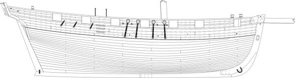
Wq3296...interesting but I have never heard of that before or seen any primary sources that show it done that way...without a margin plank that is... Do you have any other sources besides the Jim roberts book. At this early time I have always seen a margin plank (wide waterway plank) for English Frigates and larger. For a Bermuda sloop I am not as certain....but I would include it. Jim just breezed over the topic of deck planking in that book writing about a page and a half. No illustrations or mention of time periods etc. Or which decks. I am also just talking about round bowed weather decks from the period...not a forecastle deck such as shown on ships like Bellona with a beakhead bulkhead. That was handled slightly different across the flat end on the forward side of the focastle deck. But the lower decks as far as know would have been scarfed and hooked as I have shown with a wide waterway/margin plank. Jim Roberts was entirely too brief on the subject...But I would love to see additional sources about it. See this image There was no reason to use hooked planks on the forecastle deck above....however the lower decks I assumed were done just as described and shown in the earlier post of the frigate Minerva. But the waterway/margin was very wide. It is perfectly described in the Fully Framed series...Volume one for the lower decks and Volume two for the weather decks Chuck
-
David Antscherl's Swan series......Volume two I believe. I am not sure if there is a how-to but he shows the layout clearly and talks about. At any rate, a fantastic reference to have for this period all around. I also showed how I do it in the instructions for the confederacy... http://modelshipworldforum.com/resources/Confed/Chapter10.pdf Chuck
-
Nope...Just name it properly and you are good to go...A good name would be one like I posted below. Civil War Ironclad, USS St. Louis - 1:24 POF - Gateway Model Shipcrafter's Guild I am looking forward to it. Chuck
-
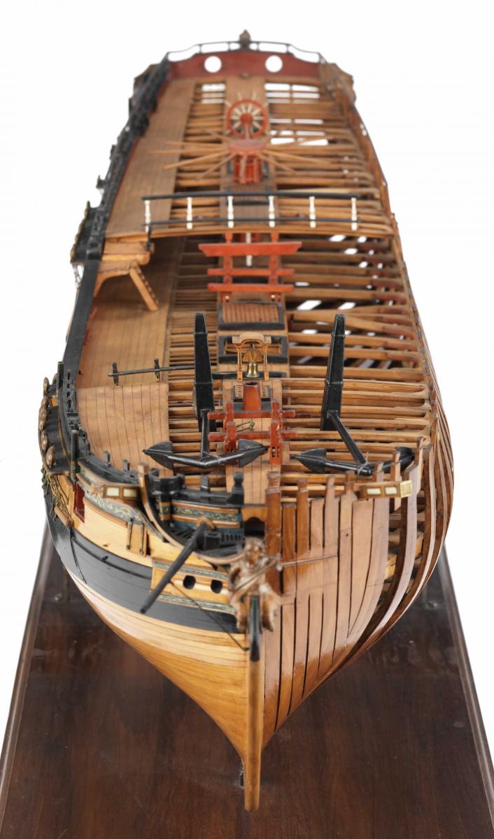
Kieth Have a look at the images from the NMM website. The planks werent nibbed at all around this time. They were "hooked" alongside the margin plank. See this image....also, the planks were curved and tapered slightly at the bow. You can see the curve here... The second photo shows a hooked or scarphed end to the plank against the margin. Both models are contemporary....and to the period we are discussing. These are considered primary sources...any secondary sources written by Roberts, Goodwin or anyone else is not nearly as weighted. If I had to choose the more accurate...I would stick with the primary sources from the time period every time. It is very hard to argue against those. Chuck
-
Cutter Cheerful 1806 by Maury S - 1:48 - POB
Chuck replied to Maury S's topic in - Build logs for subjects built 1801 - 1850
I will make an adjustment to my materials sheet. -
Cutter Cheerful 1806 by Maury S - 1:48 - POB
Chuck replied to Maury S's topic in - Build logs for subjects built 1801 - 1850
That little side to side difference wont matter. I would try and just open the slots up evenly on both sides. Use a sanding stick that is pretty large with some coarse sandpaper glued to it. I just ordered a bunch of plywood so hopefully it will be the correct thickness. If time permits I may cut some sets if the thickness is OK. Its midwest ply...not the 6mm stuff. You must look for actual 1/4" thick stuff. Dont forget to download the first chapter of the monograph online. I just added it and plan to get the others written within a week or so until I am caught up with my progress thus far. One important thing I always mention is for the builder to always measure the thickness of the ply before they start cutting. This way they can make adjustments to the slots before they start making sawdust. Its awful trying to find accurate good quality ply. It looks good so far though.... Chuck -
Ouch!! Those are awful
-
Could be pau marfim.....
-
HMS Sphynx by TBlack - 1:64
Chuck replied to TBlack's topic in - Build logs for subjects built 1751 - 1800
That is a fantastic start.... -
That looks fine Rusty. Nice save on the gallery counter. They are tricky buggers. The hard part is making sure the angle is correct so the windows fit OK. Luckily...if your windows for the galleries need some tweaking, I can just make some adjustments and cut you new ones. So dont fret about that. All you would need to do is send me some templates with the correct angles. Chuck
-
I have uploaded the Sultana practicum here..... http://modelshipworldforum.com/ship-model-build-and-practicums.php Chuck I will add the Phantom in a little while. Once I find it...I know its here somewhere.
-
If they dont put them back on the site I will fish around for the master CD;'s I have and place them somewhere on this site. Chuck
-
Looking great Dan...Have a great vacation Chuck
-
Thanks Guys Christian...I wont be plating the hull. She probably was copper plated but few contemporary models including the Surly ...They were not plated. The Surly model was painted with white stuff. I couldnt find anything definitive about it so I am going to leave the hull as is. Chuck
- 1,051 replies
-
- 5
-
-
- cheerful
- Syren Ship Model Company
- (and 1 more)
-
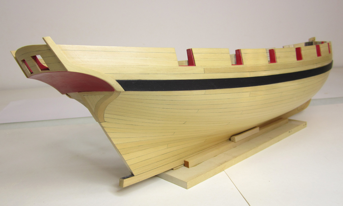
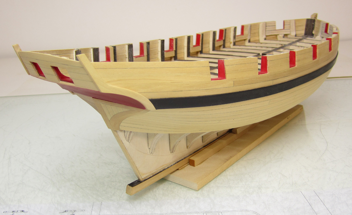
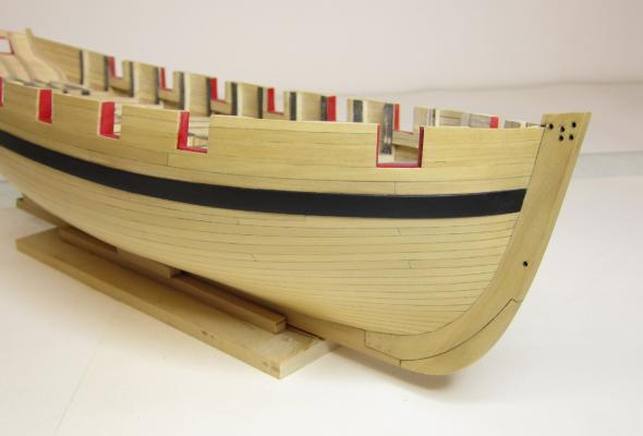
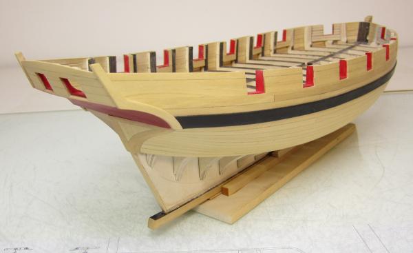
Thank you Alistair Red is a very transparent color to paint with. If you use thin coats it will be somewhat transparent. I have many more coats and more sanding to get it where I want but it will most likely have some transparency. I found some workshop time....so I finished planking the starboard side. Its a big milestone but then I look at the port side and have to repeat the entire process, including the square tuck But it all worked out very well. Once the other side is finished I can start treenailing.
- 1,051 replies
-
- 50
-
-
- cheerful
- Syren Ship Model Company
- (and 1 more)
-
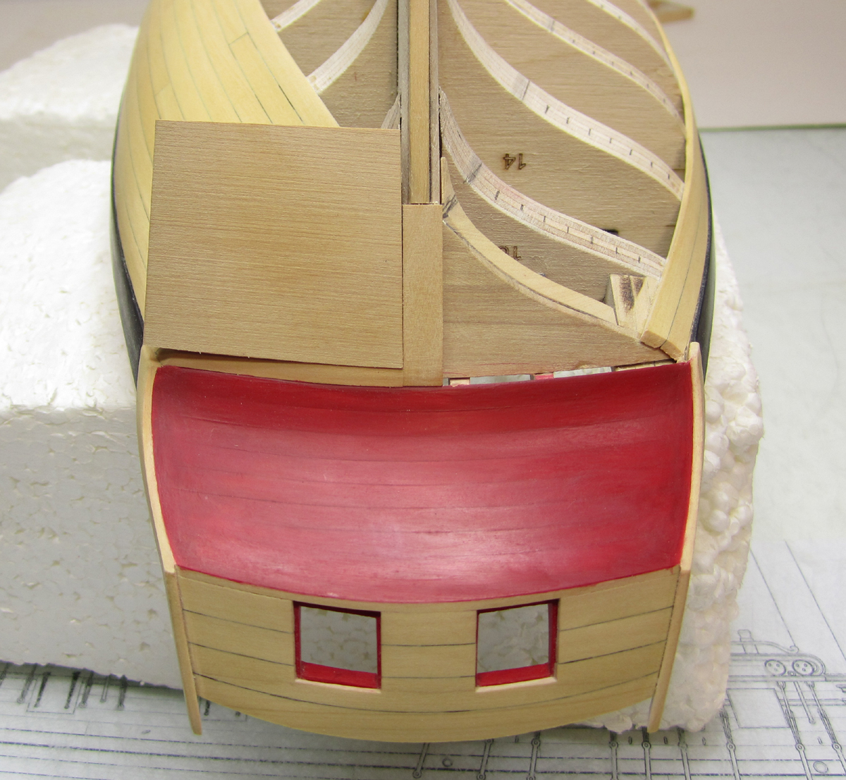
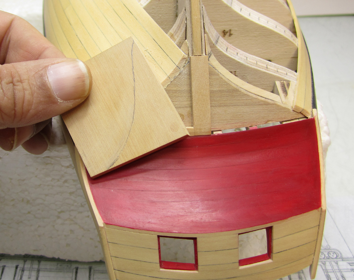
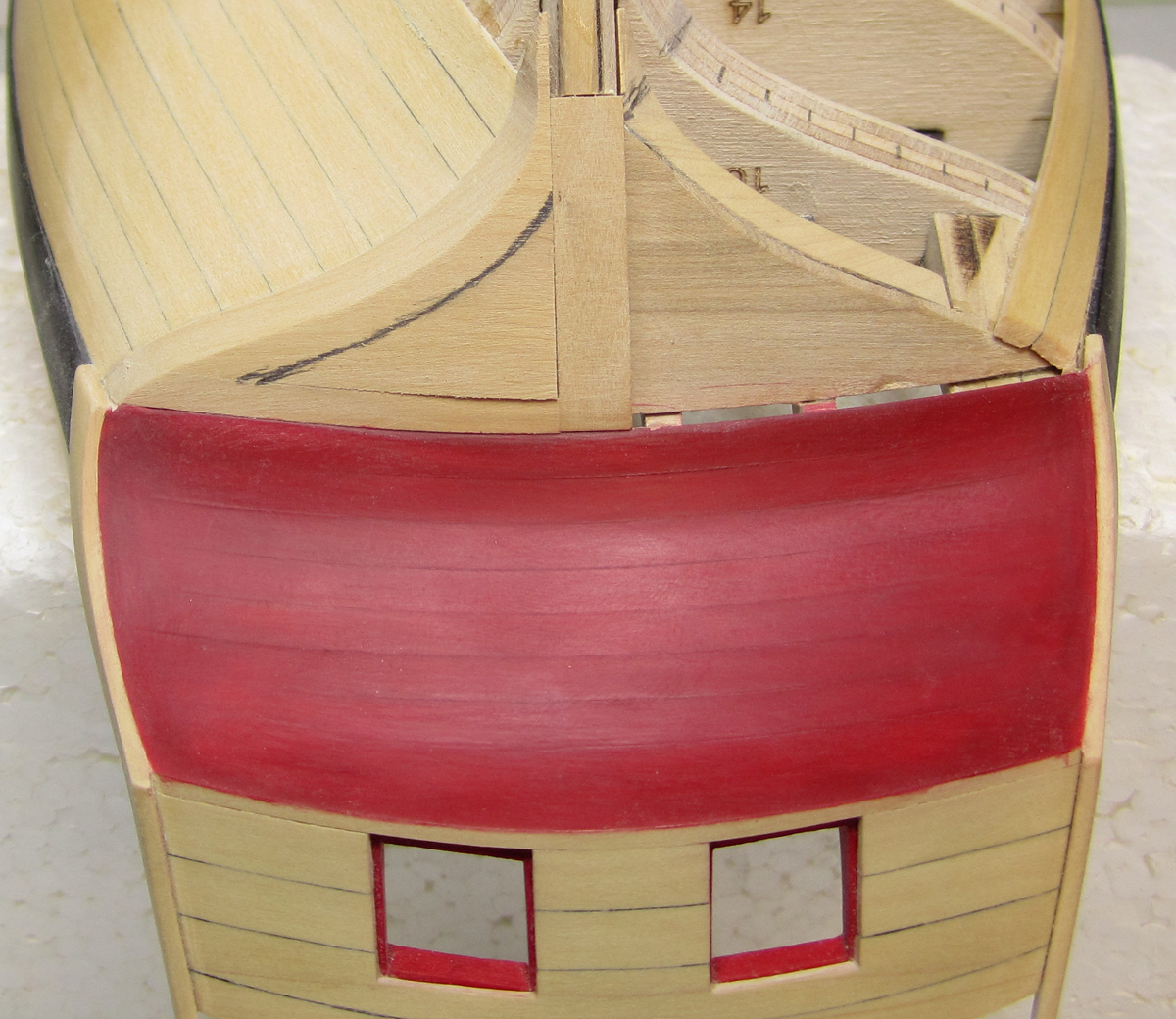
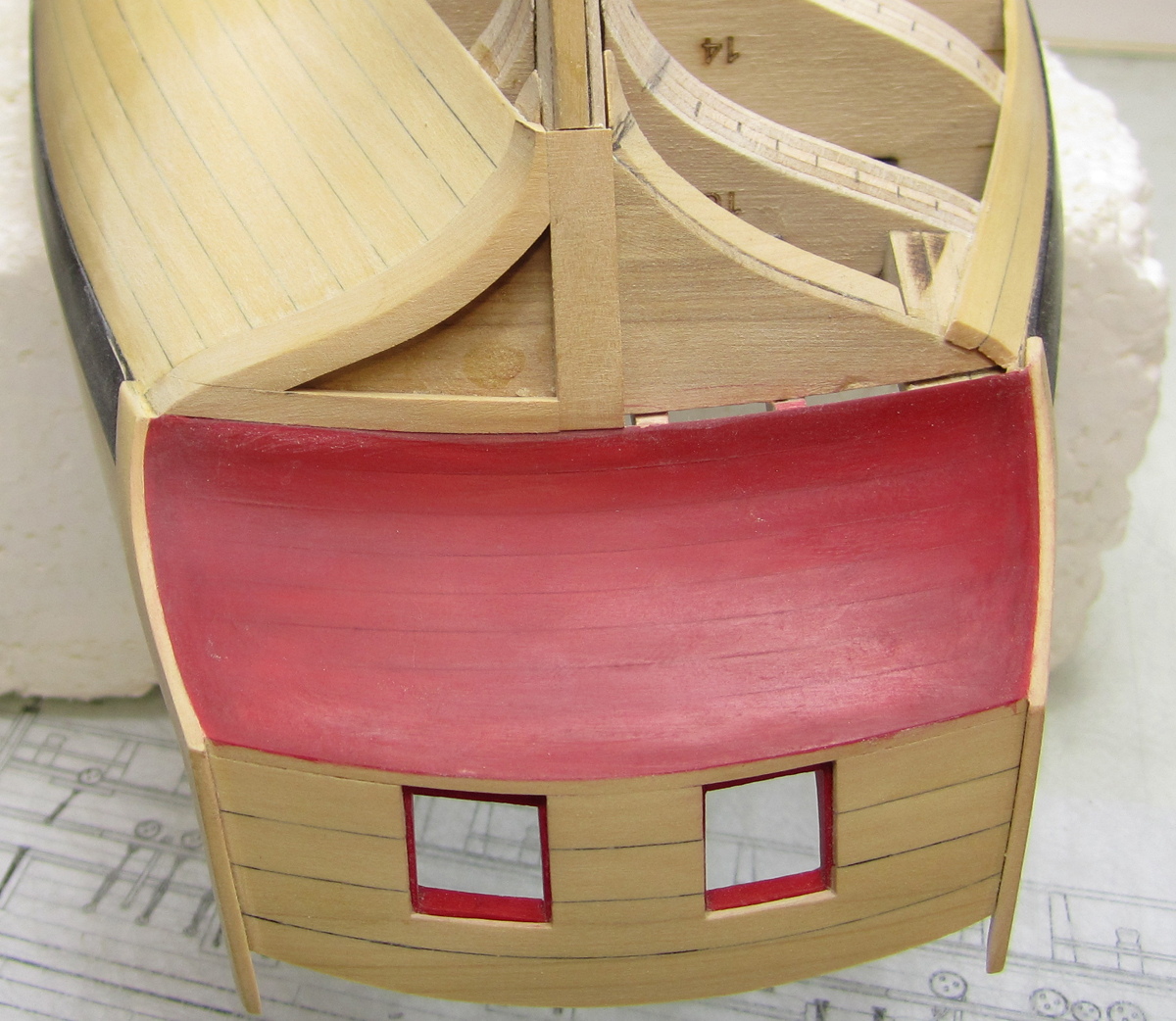
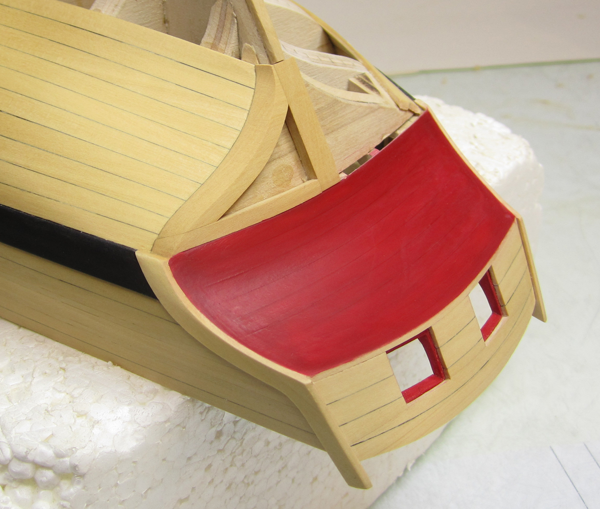
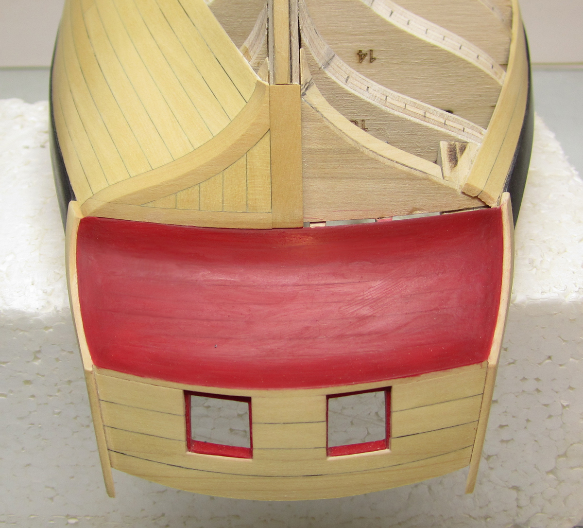
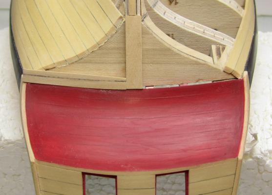
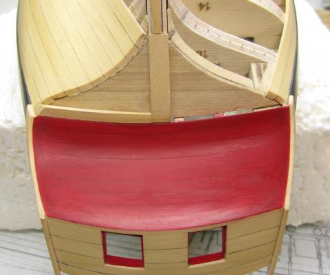
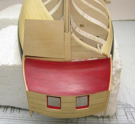
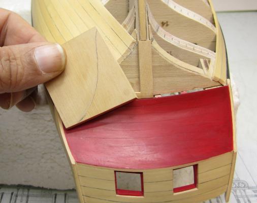
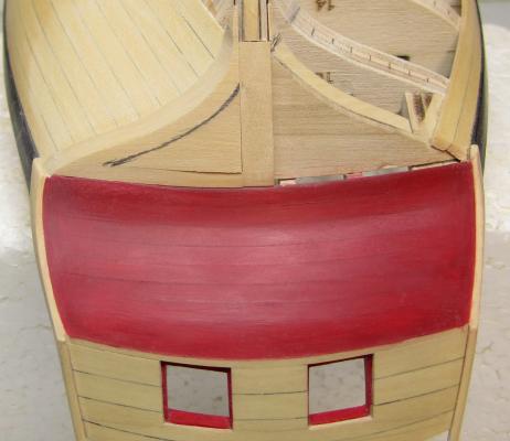
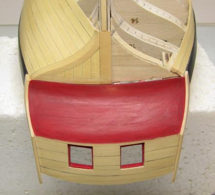
The Square tuck....Thank goodness this isnt a real POF project. Here is the simplified version. The photo below shows the first beam added which to create teh base for the stern post. It runs down the center of the square tuck so I can glue the stern post on later. It is 1/8" thick and 7/32" wide. The same width as the stern post The same photo below shows the second timber....how I took a wider piece that was 1/8" thick. I shaped it so the seam between the lower counter and this timber was very tight. Then I measured and marked it so it would be 1/8" wide as well. This will of course be repeated on the other side once it is planked. The finished timber below. Then it was time to create the side piece which will finish the square tuck frame....this was the hardest piece but not that difficult at all. I just took a larger 1/8" thick piece of boxwood and shaped it to fit tightly against the two timbers I just just completed. I tried to get real tight seams. At the same time, it hangs off the side of the hull. Then I traced the shape of the hull against the back of this piece. Heres what the tracing looks like. The piece was cut to shape on the scroll saw. Then, this piece was temporarily glued back in position with just a small dot of CA. This was done because it will need to be removed after it is faired with the hull planking. See below. And as done before, I drew another line to establish a 1/8" wide finished timber. This was cut out and glued into position finishing the frame for the square tuck on this side of the hull. Here is what it looks like. Finally....it was planked inside with vertical planks the same width as the hull planking. Tarred seams were simulated. I was very careful to get very tight seams. In actual practice these planks would be normal thickness and the ends resting in a rabbet along the edges of the square tuck frame. In my case though, I just faked it using planking that was actually 1/8" thick which is the same thickness as the frame. It all worked out in the end. I am quite pleased with the results as this is normally a really tough detail to model convincingly. Now to touch up the red paint on the counter or maybe its just best to wait till the planking is all done. I can now start planking the last belt on the starboard side.


- 1,051 replies
-
- 49
-
-
- cheerful
- Syren Ship Model Company
- (and 1 more)
-
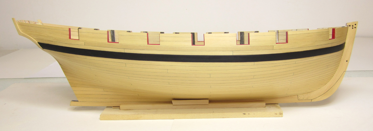
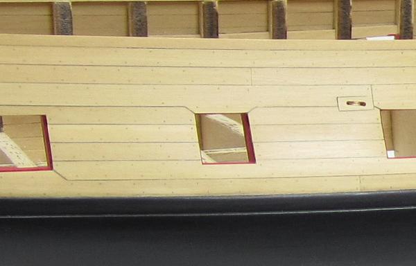
Thanks Any art store will have the pinstripe tape. Graphic arts tape... Clinker planking may in fact be easier for you but in the case of the Cheerful it would just be wrong historically. I find it difficult to clinker plank a hull. I havent seen many hulls that are done properly or to my satisfaction...so I chose a carvel planked hull. I think most model builders prefer this anyway. Its what they are used to.
- 1,051 replies
-
- 3
-
-
- cheerful
- Syren Ship Model Company
- (and 1 more)