Chuck
-
Posts
9,703 -
Joined
-
Last visited
Content Type
Profiles
Forums
Gallery
Events
Everything posted by Chuck
-
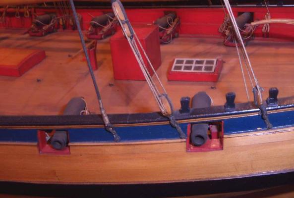
 Nicely done Dan. Cannon rigging look good. Chuck
 -
Basically you should taper the bulkhead former a bit more than 3/32' thick at the stern just to be safe. This was my first kit design trying out the rabbet strip concept. From the bearding line to the rabbet strip it should really be a gradual tapering to 1/16" thick. But after the hull is planked it will be a bit thicker than the stern post, so yes, you will need to gradually sand the hull planking along the stern post so it sits flush with the stern post (1/8" wide). Because the planking is 1/16"' thick....its really too thick for this scale. So gradually sanding the finished planking toward the stern post to make it flush will be required. It only need to be done really at the lower corner of the stern post where the keel meets it. Because the original kit supplied basswood at 1/32" thick couldnt be used as planking material...its real crap and would literally fall apart. I had to substitute thicker 1/16" basswood strips. This means it will stand proud of the stern post and keel by 1/32" This extra thickness needs to be gradually knocked down to sit flush against the 1/8" wide stern post and keel after you finish planking the hull and add them..
-
Thank You!!! Its Windsor & Newton Acrylic Galleria paint from a tube. The color is crimson. Chuck
-
You are correct. There would not have been breech rings at that time. But it simplifies the process of rigging them. Have you ever tried to splice plastic rigging line properly? So it was an oversimplification to spare folks the headache when trying to rig the breech line around the button of the cannon as supplied by MS. Especially after a fine paint job. I talked about the decision quite a bit on the original build log for the prototype. Nice catch again and hopefully this log will now serve as the place to get the scoop on that. Its looking great Augie. Chuck
- 2,191 replies
-
- 3
-

-
- confederacy
- Model Shipways
- (and 1 more)
-
The loose end would indeed be fixed to the shroud itself. Just above the upper block. Think of it in terms of mirroring the way the lanyard is fixed above a deadeye. Its the same thing.
-
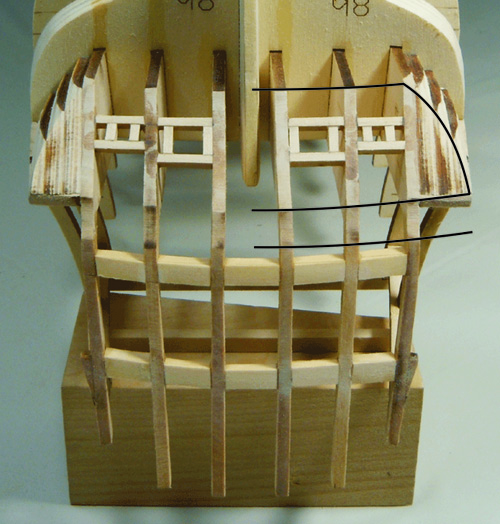
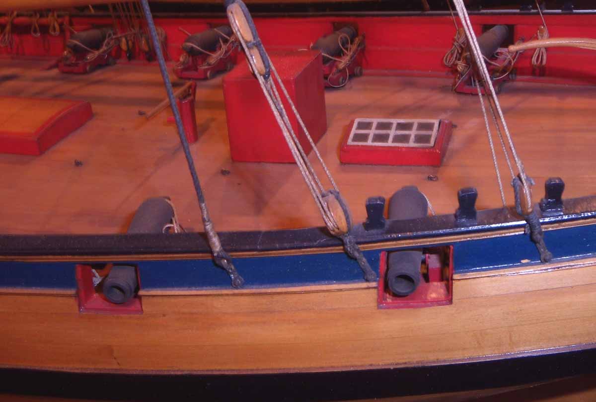
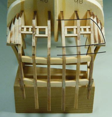
Its hard to see the definition in the lower and upper counters. This can be tricky unless you define it better. Note in the first picture I drew the shape of the counters with lines on the right. But on the left side you can still see a very crisp edge and corners that define these areas. I would take some sandpaper and sanding sticks to your counters and see if you can better define their shapes as shown in this photo. Remember the upper counter (the skinny long one on the bottom in these photos) needs to be a consistent width as it works its way port to starboard. Most folks have a tendency to make it wider in the middle and I can see that happening in your pictures. You can correct this buy working the sand paper across the counters carefully as you fair it more. Remember to try and create hard line breaks between these counters and the sides of the lower counter. Chuck
-
Thats the plan Druxey. We shall see how it goes. I think it will work out OK. Bill, All laser cutters cut on an angle. You can minimize it a lot but never get rid of it entirely. Basically the laser is cone shaped as it travels through the lense that focus' it. Much like how you would focus the sun through a magnifying glass. So it gradually comes to a point. If you focus that beam so the point ends in the center of the thickness of wood you can minimize the angle of cut but its hard to do. So its just a matter of focusing well and the, choosing the proper laser power for that thickness along with the most appropriate speed. If you pick the slowest setting possible along with the least power possible to just cut through the wood, then the Kerf will be as thin as possible......thus reducing the angle. The angle is always more noticeable on thicker pieces which are few on a model. So I enlarge them by 1% or 2% to compensate. Once the laser char is removed with a sanding stick while you at the same time make a true 90 degree angle the part will be the appropriate size. Its just a fact of life for laser cutters and all kit cut pieces. But you can minimize it quite a bit with practice, trial and error. Chuck
- 1,051 replies
-
- 10
-
-
- cheerful
- Syren Ship Model Company
- (and 1 more)
-
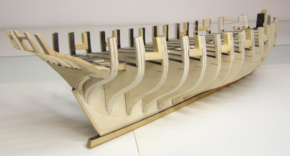
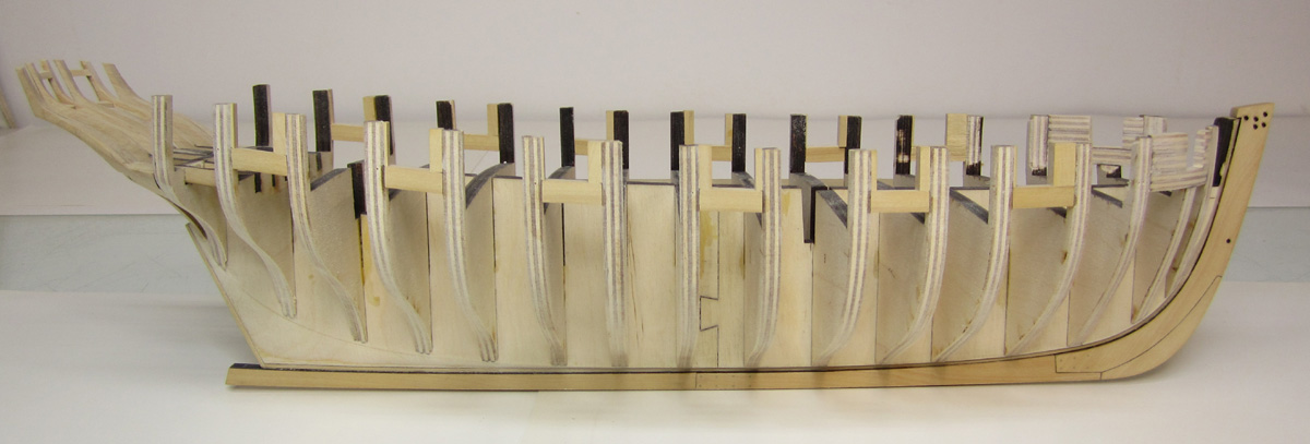
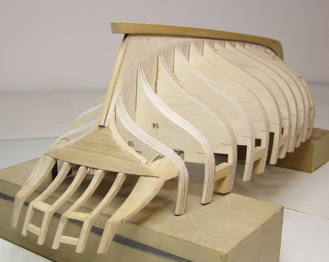
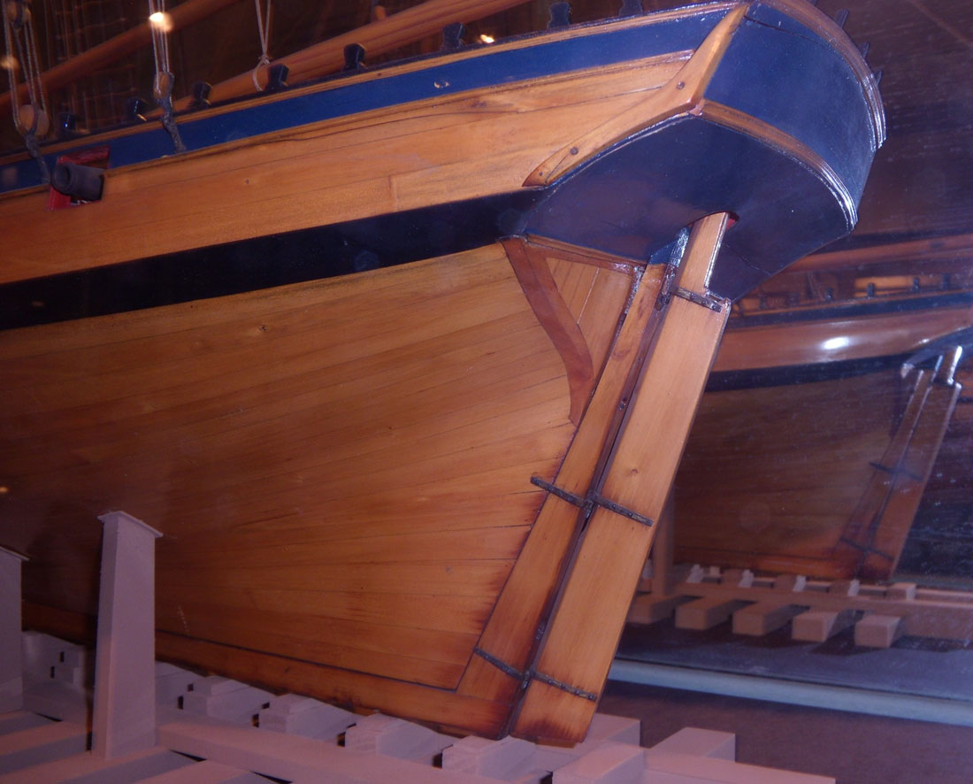
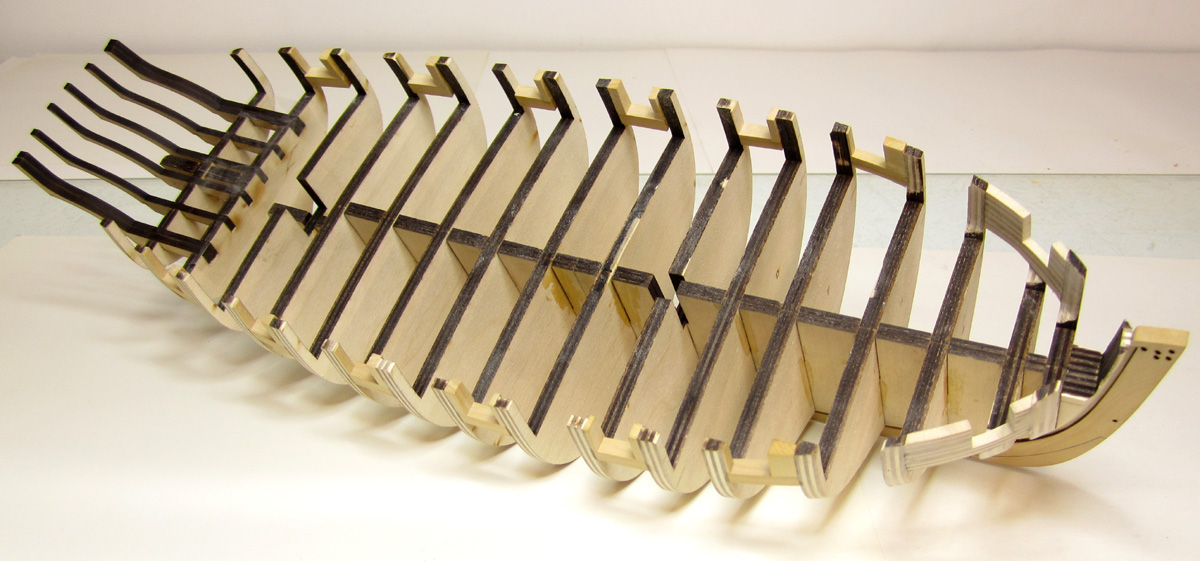
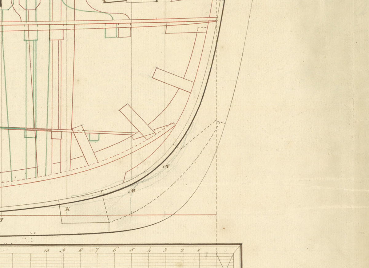
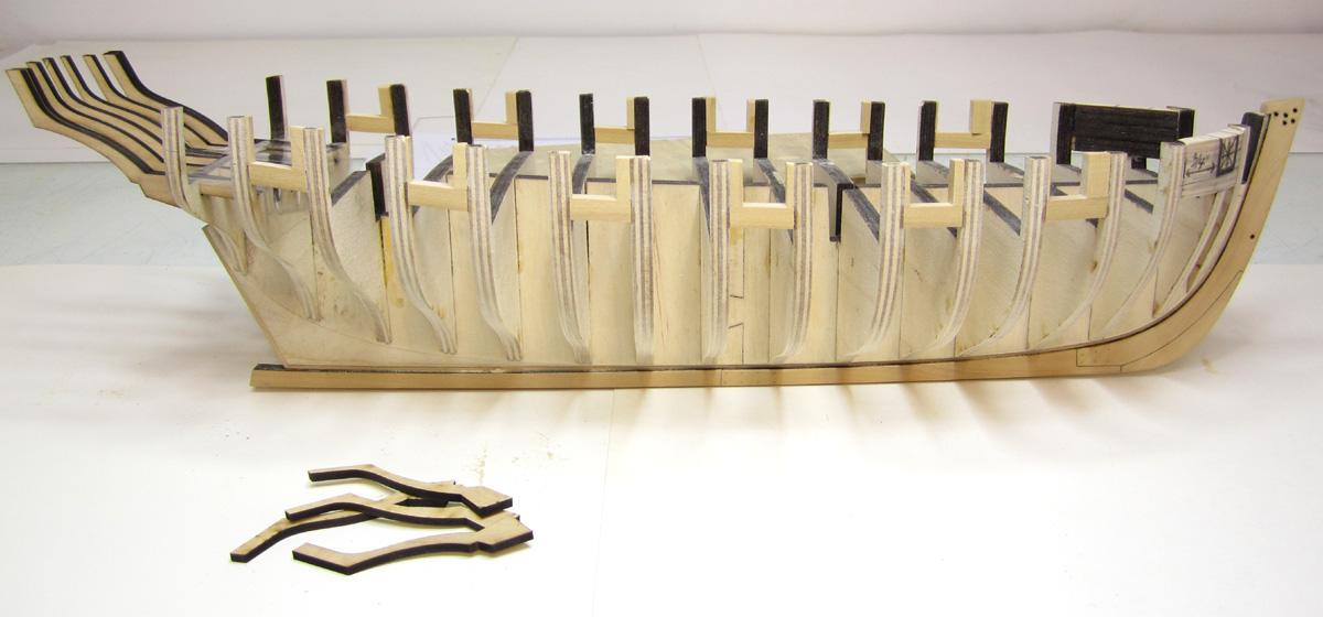
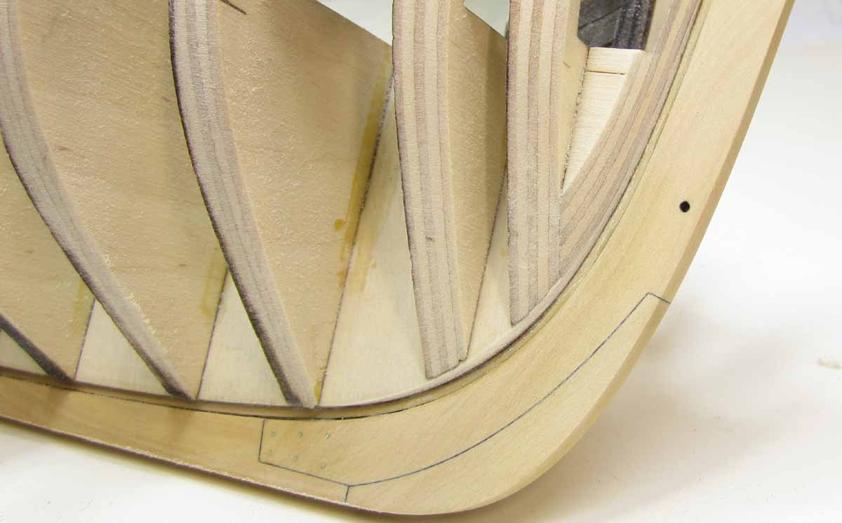
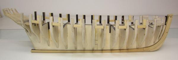
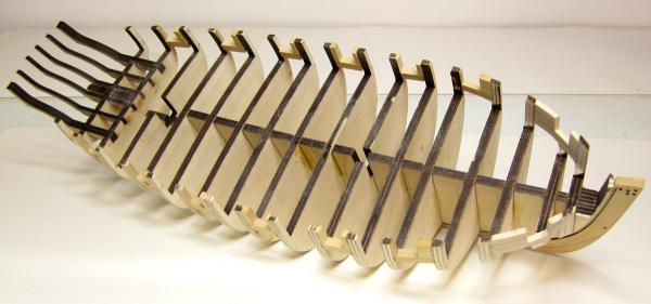
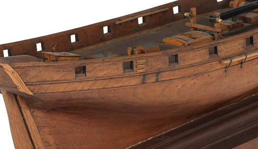
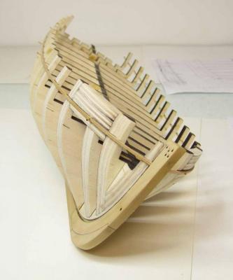
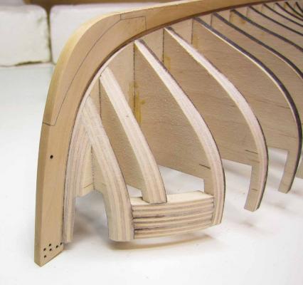
I managed to finish the skeleton for Cheerful today. So its now ready for planking. The stern framing was pretty standard although the design concept was modified for the square tuck. This is a feature that is rarely shown correctly on these cutters. There are some pretty complex angles. Its hard to tell in the images but the square tuck is not flat and completely perpendicular to the keel. It has a slight convex curve as it works its way from the center outward. It isnt complete yet. The actual framed square tuck will be added after the sides of the hull are planked. Its probably the trickiest part on the model but I simplified it quite bit as far as the construction is concerned. But when its done it should look exactly like the real thing. Thats my hope anyway. The first image shows the Rogers collection model with its square tuck. The frame around the vertical planking will be added after the hull is completely planked. Then I will fill it in with the vertical planks. Chuck


- 1,051 replies
-
- 32
-
-
- cheerful
- Syren Ship Model Company
- (and 1 more)
-
Oops I meant earlier......wrong choice of words.
-
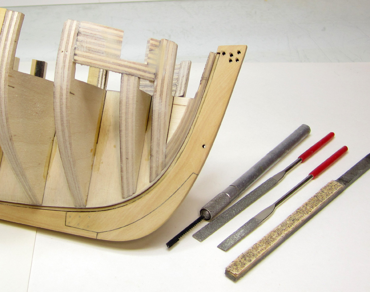
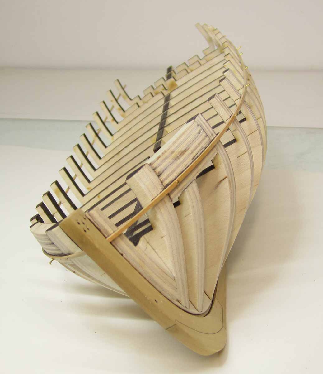
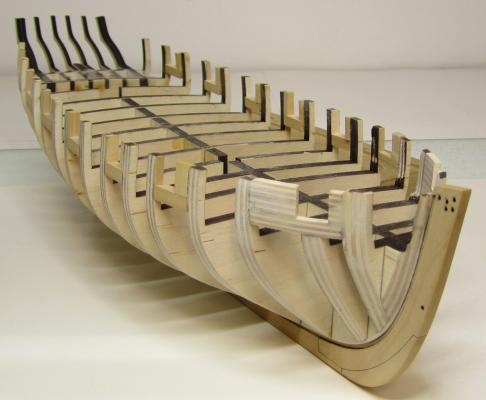
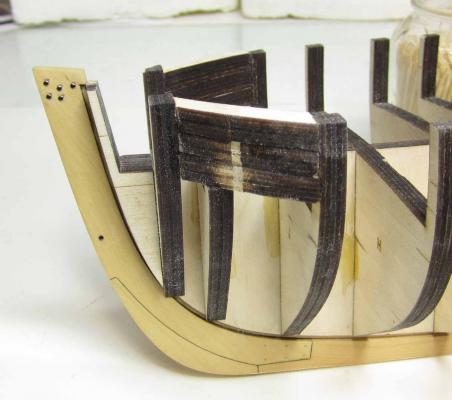
Thank you. Its a tough thing to describe in writing. It is so much easier to demo it. That was a good idea about doing another demo at next years conference. I will talk it over with the guys. I actually did one for my local club members. I just showed them how to prepare the surface and paint a solid color without brush strokes. What brushes to use and how to paint a straight line without using tape. When I was in college I had to take an entire course in color theory where we had to paint 2" x 2" square swatches of solid color. Th e teacher was rough to say the least. If the painted swatch wasnt completely flat without brush strokes and perfectly even color you would fail. I can only now see where that class had a purpose that was worthwhile so many years later. I had to paint hundreds and hundreds of swatches. Oh the memories of art school. Anyway, after spending hours cleaning the shop, I had a chance to cut those forward ports. I used a scroll saw blade that I snipped a small length off off. I placed it in my hobby blade handle and used it to cut out the ports. You can see it in the photo. Then it was a matter of refining the sides of the port opening with files and chisels. This was to try and get straight sides and sharp corners. Then I wanted to do a quick preliminary fairing inboard at the bow. I didnt want to look at that disgusting thick bow with all the laser char as I planked the hull. You can look at earlier pics to see just how thick it was. I used a sanding drum in my dremel to cut down the thickness to around 1/8" thick at the bow. It needs much more attention and will eventually be thinner. But its easier for me to look at now as I work on other areas. Tomorrow I will start framing the stern permanently. Then its on to planking. You will see how rough and uneven the inboard side of the bulwarks look. I wasnt careful about how uneven the pieces of wood stuck out on that side. As long as they were deep enough to faired later I didnt care. I will take the sanding drum to it after the outboard planking is done and it wont take long to make it all look nice and clean. You can start to see that taking shape at the bow after just the preliminary thin-down. The stern frames are still just taped into place temporarily. You can see how they are let into slots in the two last bulkheads. It makes proper placement a lot easier.
- 1,051 replies
-
- 29
-
-
- cheerful
- Syren Ship Model Company
- (and 1 more)
-
Gesso Thick milky white base used to coat canvases for painting. see this link http://www.art-is-fun.com/what-is-gesso.html Chuck
- 1,051 replies
-
- 4
-
-
- cheerful
- Syren Ship Model Company
- (and 1 more)
-
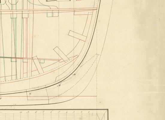
Hopefully not to confuse the situation, But here is a better image of Cheerfuls stem parts. You are using the outboard plan. This is from the inboard draft. I have seen this arrangement on two other cutters but sadly these details are not shown on most cutter drafts. The Alert is much younger also so this may not even be applicable. But I wanted to mention how all of the lines on the draft you posted are dashed for these elements. On the inboard sheet however it shows the dashed lines as if they were parts cut for the other side of the stem only. Meaning that the stem was intended to be cut in one piece and the two other elements used for the boxing joint and apron on the other side only. That is ...if I am reading the draft correctly. It seems unlikely that they could find such a large piece to make the stem like that. So I agree with Ed that in all likelihood it depended on what wood they had on hand and probably ended up with a much different "made up" stem that may not have matched any of these choices. So I simplified it a great deal for my project because I dont find all of these elements an attractive addition to a ship model anyway. Its too distracting and busy. In fact....you never see the separate pieces on almost all of the contemporary cutter models I have seen. The stem is always one piece down to the boxing joint.
-
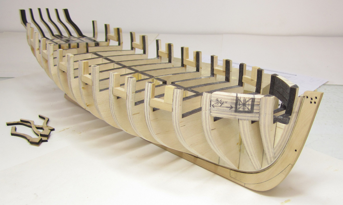
Thanks Guys.... Tom, I will bring her to the meeting tonight along with the plans to show our Jersey Club Members. Its bring a model night!!!! I finished framing the port openings in Boxwood. I used the reference line from the batten to mark to top of the gunport sills. They should paint nicely because they are all boxwood. Unlike the first port which will be cut from ply fillers. You can see it marked in pencil. I am about to cut it out right now. I also laser cut and tested the stern frames. They are not glued in yet. Its just a test and all looks good. It helps make the shape of this little cutter come to life. I will begin permanently framing the stern as soon as I cut those two forward ports. Before painting them I will prepare the surface with wood filler or even gesso to smooth it out. This creates a nice surface to paint on after its sanded with a very fine sandpaper.


- 1,051 replies
-
- 28
-
-
- cheerful
- Syren Ship Model Company
- (and 1 more)
-
Storing Wipe-on-Poly
Chuck replied to ortho85's topic in Painting, finishing and weathering products and techniques
I have yet to use a full can before having to throw it away. Th e plastic top gets crusty and the poly gets thicker over time. I end up buying a new one every six months. So I am very interested as well. Chuck -
Kevin....look a few posts back. It was already discussed. Thanks guys, I am glad you are enjoying the process. Yes ....this is the process. Usually any questions are bounced off a few guys and different research aspects are exchanged. I figured it was best to do it publicly so everyone can see the decision making process. Most of it is done. I have only a few things left to decide on.... Chuck
- 1,051 replies
-
- 6
-
-
- cheerful
- Syren Ship Model Company
- (and 1 more)
-
Yes Alistair...that is exactly what a buckler is. I have seen bucklers in many configurations. For example...sometimes a half lid was hinged on the bottom of the port opening and the buckler used only on the top half. In other instances the buckler was full size for the port. They are usually temporarily secured by ring bolts on the inboard side of the buckler and tied off to ring bolts on the bulwarks. Even the same ring bolts used for the breech line of the cannon or the gun tackles.
- 1,051 replies
-
- 5
-
-
- cheerful
- Syren Ship Model Company
- (and 1 more)
-
That absolutely works for me.....makes as much sense as any other theory I have thought of. That would mean Cheerful had no lids but probably had a rabbet so bucklers could be used in rough waters. Thats my story and I am sticking to it.
- 1,051 replies
-
- 10
-
-
- cheerful
- Syren Ship Model Company
- (and 1 more)
-
Also note the vertical planking on the square tuck in that drawing. This cutter has the same based on the original planking expansion. Normally you see the diagonal planking.
- 1,051 replies
-
- 2
-
-
- cheerful
- Syren Ship Model Company
- (and 1 more)
-
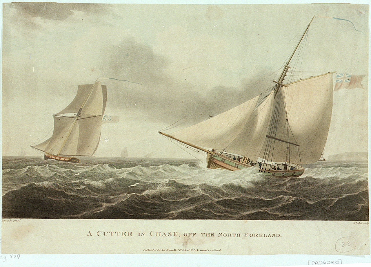
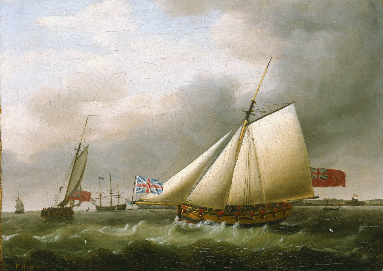
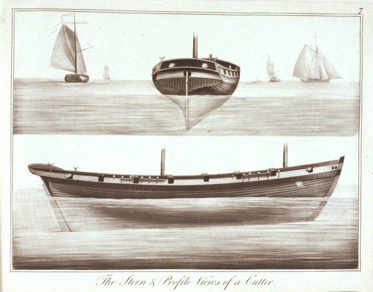
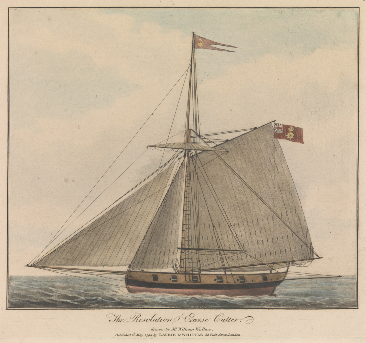
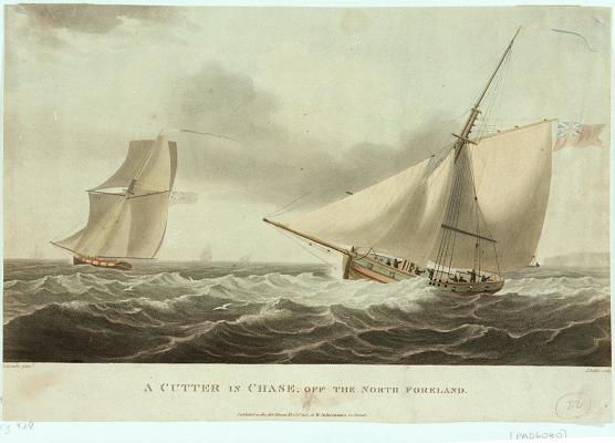
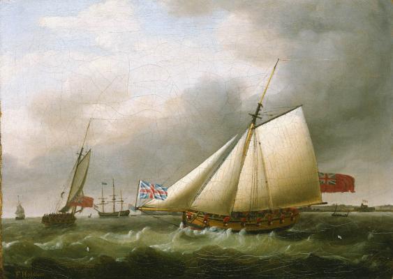
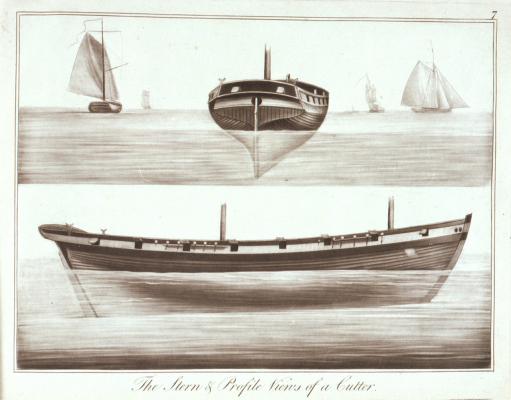
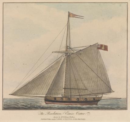
I absolutely agree and I thought the same thing. BUT....then I found these. All contemporary and from the same time period. I have dozens more with and without port lids. I guess we shall never know. I will add the rabbet......and have no lids. That is a safe bet I think. Chuck
- 1,051 replies
-
- 7
-
-
- cheerful
- Syren Ship Model Company
- (and 1 more)
-
As I am about to start framing the ports, I would like to have a bit of a discussion about the. Please feel free to chime in if this is something you are familiar with. I have seen cutters with and without port lids in paintings and drawings. I am talking about 1800-1830ish. My issue is that I have never or rarely seen a contemporary model or set of plans with port lids. I am already resolved not to show them on Cheerful. BUT, that leads to my question. On many contemporary models I can see the rabbet around the port opening. On others still there is no rabbet. I can only assume there wasnt and standard with this. Maybe some sort of buckler was used rather than a port lid. But then why some models without a rabbet. I have yet to decide if I should show this feature of a rabbet around the sides and bottom of the port openings. Cheerful in the rogers collection has them This contemporary model does not...except at the bottom maybe... All of the others from this period that I have seen have no rabbets. Any thoughts or research out there to help me in my decision? Thanks in advance.
- 1,051 replies
-
- 3
-
-
- cheerful
- Syren Ship Model Company
- (and 1 more)
-
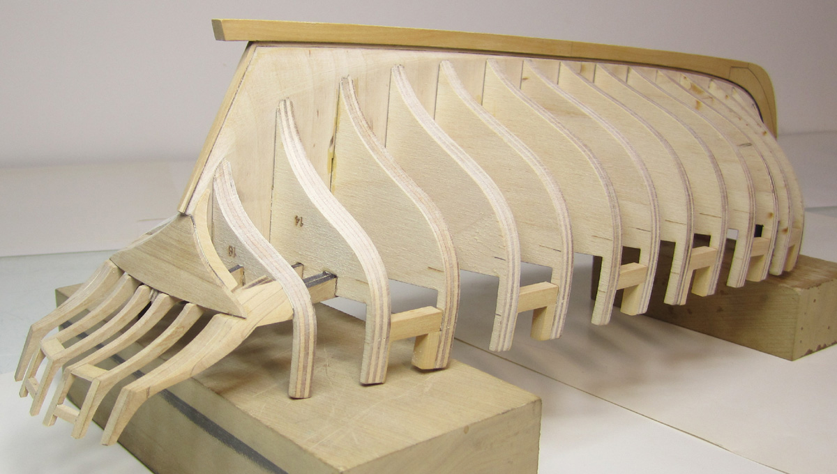
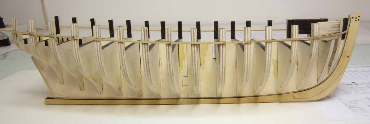
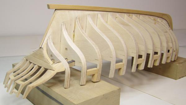
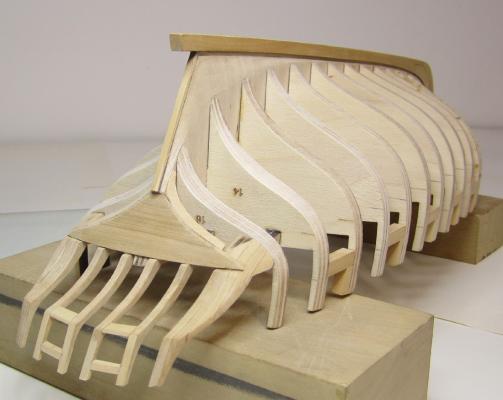
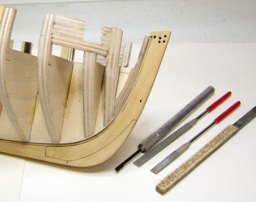
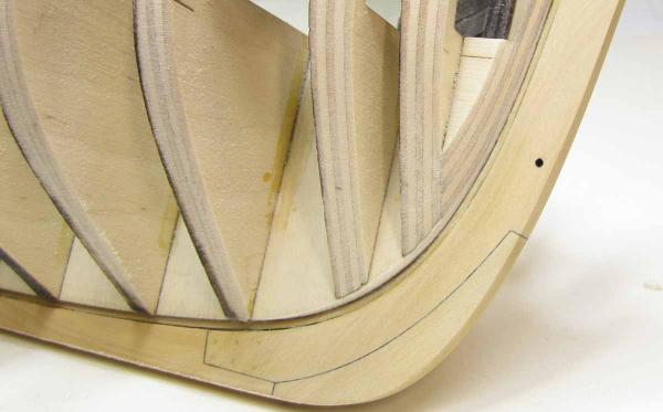
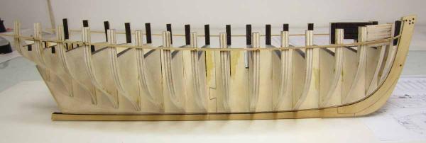
Today I wanted to get the crappy part out of the way. What a mess. Fairing the outside of the hull before I start putting in the port sills. Lots of saw dust. You folks are very familiar with this. Even with a smaller hull it took the whole day. This is the single most important part of the project. Unfortunately because its such a pain its easy to understand why people rush through it only to have issues later on. At the bow is the usual "Bow filler piece" and a few horizontal pieces which is where the forward port will reside. Fairing the bow was challenging. Whenever you think its done...its really not. This is easy to spot using a batten. I dont angle my rabbet for the planking until this stage. And its important. Most folks angle the rabbet before gluing the bulkheads into the former. But I can never get the angles right. Its easier for me to visualize when fairing the bow and inserting battens every now and again to see how they fit. Before fairing After a good start at fairing the bow. Notice how the bulkhead former within the rabbet is faired to match the angle of the bow filler after its faired. If you dont do this then the plank wont fit nicely into the rabbet and defeats the purpose of having one to begin with. This is what takes lots of time. Small chisels nd sanding sticks...the usual suspects to do it. I am using the laser char on the bulkhead edges to check how the fairing is progressing as I work towards mid ship. Then I switch around and work from the stern to midship again to complete the fairing. Here are some battens added to check the run of the port sills. There are laser reference marks on each bulkhead as is usually the case. After some careful adjustments the top of the batten was marked off on each bulkhead edge to indicate the top of the port sills. Notice how the batten fits into the rabbet and because of how its faired, I didnt have to even pre bend this strip. It lays in there perfectly and no pins are used to hold it in the rabbet. That will make planking so much easier.....which would have been a fight if I didnt take my time with this fairing. I am gald its all done, but I can still see some spots... Tomorrow I will add the port sills and port framing before starting on the stern framing.
- 1,051 replies
-
- 24
-
-
- cheerful
- Syren Ship Model Company
- (and 1 more)
-
Yes indeed it will Lou. Thanks for the kind words. Yes I plan on using National balsa when the time comes. I have used them a lot in the past and they are my go to source. The last batch of ply I got from them was awful though so I will have to call them first and make sure I get the good stuff. It is so great see you back on the site. I am literally working on her as we speak. Chuck
-
Its a great start and dont hesitate to ask me any questions. The Mayflower II was a fun project to build. Chuck
-
I received my copy and read through the entire book. Its a just a great book and I have already picked up a few tricks from it. There are quite a few nice techniques described in this book that will help you as a model builder construct fittings and ship's details that would be part of any Eighteenth Century vessel. I highly recommend it. Well worth a look!! even if you dont plan on building the Comet. Chuck