
Supplies of the Ship Modeler's Handbook are running out. Get your copy NOW before they are gone! Click on photo to order.
×
Chuck
-
Posts
9,449 -
Joined
-
Last visited
Reputation Activity
-

 Chuck got a reaction from FrankWouts in Sloop Speedwell 1752 by Chuck - Ketch Rigged Sloop - POF - prototype build
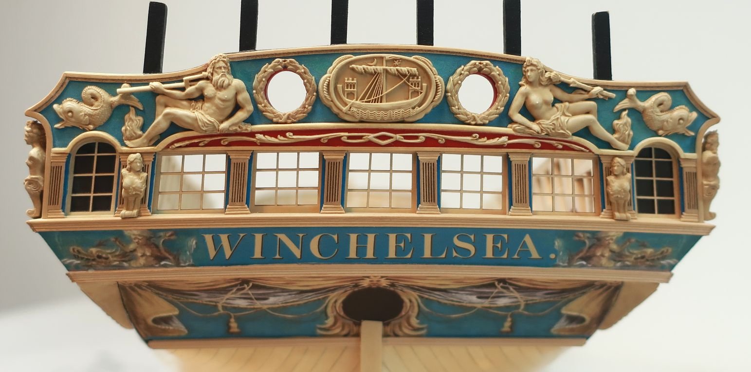
The hawse holes can be complex but if you spend a lot of time preparing and measuring it will go smoothly. Before I begin describing my process here is a look at the contemporary model. You can see many close up details here.
I started by preparing some new templates. They are very much like the other templates but I wanted to add some other reference lines to help me more with aligning the hawse holes. So these are the ones you want to use when you get this stage.
You will note a few things in that photo. First you will see the dashed vertical lines I added that extend up to the cap rail. These will allow you to mark the locations of the hawse holes on top of the cap rail. To do this I cut some painters tape to the width of the hawse holes and placed it on the cap rail using the template as a guide. The tape runs parallel to the keel across the cap rail.
You will also notice how I cut the hawse holes from the template so I could use it as a stencil after taping it to the hull. I also cut an opening to mark the location of the hawse hoods or naval hoods. These are the plates that sit over the planking. The template sits on top of the wales as before. The forward edge sits against the stem.
I of course cut away the molding strip on the hull before I taped the template in position. I dont want to forget to mention that. Then I traced the hawse holes onto the hull.
On the inboard side of the hull, I prepared another template specifically for the hawse holes. Note the dashed lines again that extend to the cap rail. This template was lined up with the tape I placed across the cap rail. This will be the path I plan to drill through the hull for the hawse holes. This was a lot of measuring and planning to come up with these templates but it all worked out well. Just trace the hawse holes on the inboard side as well. Note how the template is sitting on the deck which establishes the correct height...I hope.
I didnt take any pictures right after drilling the hawse holes. I cant believe I forgot to do it. But let me explain the process. I drilled them out using progressively larger drill bits. I drilled from both sides. I drilled half way through from the front and then switched to inboard. I drilled half way through until the holes met in the middle and the first small hole was clear and through. Then I switched to a slightly larger drill bit and repeated the process. I increased them until the hawse holes were almost full size and then I switched to a round file to clean them up and enlarge them further.
THE ENTIRE time while drilling from the outboard side I used the blue tape on the top of the cap rail to guide the drill bit at the same angle. Following the keel. The hawse holes are almost level in height inboard and outboard with only a slight upward angle needed as you drill from the outboard side. A very slight angle. Not to worry if its not exact because when you dill from the inboard side to meet the outside hole it should all meet up decently.
I touched up the red paint inboard and used a soft pencil to darken the insides of the hawse holes black...to represent lead or tin I suppose.
Next up was to add the Hawse hoods or Naval hoods on the outboard side. These are made in two layers. They are laser cut and on the outermost end is a laser etched detail. This small etched detail wouldnt be difficult to carve with a sharp chisel. But I just assume etch it onto the ends. This means you must clean up the laser char from this "stepped" detail. I used a small flat needle file. It doesnt have to be perfectly clean either. Just do the best you can. Mine isnt perfect by any means and this little bt of char will actually accentuate the carved detail. Look at the photo of the contemporary model to see it on the original. The parts on the left are not yet cleaned.
The two layers are glued together carefully. The circles for the hawse holes are registered together. But a little tip....while gluing the two layers you can actually pre bend the hoods so they will stay bent and curved once the glue dries. Its hard to see this in the photo but the one on the right is curved to almost match the hull curvature exactly. This will make it so much easier to glue onto the hull.
Here you can see the two layered assembly glued onto the hull. Please note that after gluing the two layers together the inside edge against the stem must be beveled. I also cut these pieces a but longer (not by much) so you can line them up with your hawse holes drilled through the hull. Just carefully bevel the edge a little at time until as you are test fitting it on the model it the hawse holes line up. The holes themselves are also slightly smaller on this so you will have even more wiggle room to enlarge them after this is glued on the model. I think they look pretty good and look quite a bit like the contemporary model.
Lastly...the bolster. This piece is slightly thicker and not long enough to bend easily. So I laser cut it on even thicker boxwood stock. Its easier to sand the curve into the back side rather than bend it to fit on the hull. Once the bolster sits nicely on the hull and the curve matches, you can sand the outside to match. This will leave the overall thickness at about 3/64". Maybe slightly more.
Round off the top edges and sides but dont touch the hawse hole cut-aways just yet. This will be done after you glue the bolsters on the model. You will notice the oddball shape of the hawse hole cut-aways. They dont look like half circles. This is on purpose. Remember the hawse holes are drilled through parallel to the keel. So these weird shaped half holes are shaped like l=this so you can file them to the proper shape. Use a round file to open them up to match the angle of your hawse holes through the bulwarks. I hope that makes sense. When initially gluing the bolster on the hull, line up the iboard side to match the profile of your hawse holes. Just like in the photo. Then use your file to shape them.
They will or should be opened up to look like this. The holes were touched up and blackened with a soft pencil.
-

 Chuck got a reaction from Hubac's Historian in Sloop Speedwell 1752 by Chuck - Ketch Rigged Sloop - POF - prototype build
The hawse holes can be complex but if you spend a lot of time preparing and measuring it will go smoothly. Before I begin describing my process here is a look at the contemporary model. You can see many close up details here.
I started by preparing some new templates. They are very much like the other templates but I wanted to add some other reference lines to help me more with aligning the hawse holes. So these are the ones you want to use when you get this stage.
You will note a few things in that photo. First you will see the dashed vertical lines I added that extend up to the cap rail. These will allow you to mark the locations of the hawse holes on top of the cap rail. To do this I cut some painters tape to the width of the hawse holes and placed it on the cap rail using the template as a guide. The tape runs parallel to the keel across the cap rail.
You will also notice how I cut the hawse holes from the template so I could use it as a stencil after taping it to the hull. I also cut an opening to mark the location of the hawse hoods or naval hoods. These are the plates that sit over the planking. The template sits on top of the wales as before. The forward edge sits against the stem.
I of course cut away the molding strip on the hull before I taped the template in position. I dont want to forget to mention that. Then I traced the hawse holes onto the hull.
On the inboard side of the hull, I prepared another template specifically for the hawse holes. Note the dashed lines again that extend to the cap rail. This template was lined up with the tape I placed across the cap rail. This will be the path I plan to drill through the hull for the hawse holes. This was a lot of measuring and planning to come up with these templates but it all worked out well. Just trace the hawse holes on the inboard side as well. Note how the template is sitting on the deck which establishes the correct height...I hope.
I didnt take any pictures right after drilling the hawse holes. I cant believe I forgot to do it. But let me explain the process. I drilled them out using progressively larger drill bits. I drilled from both sides. I drilled half way through from the front and then switched to inboard. I drilled half way through until the holes met in the middle and the first small hole was clear and through. Then I switched to a slightly larger drill bit and repeated the process. I increased them until the hawse holes were almost full size and then I switched to a round file to clean them up and enlarge them further.
THE ENTIRE time while drilling from the outboard side I used the blue tape on the top of the cap rail to guide the drill bit at the same angle. Following the keel. The hawse holes are almost level in height inboard and outboard with only a slight upward angle needed as you drill from the outboard side. A very slight angle. Not to worry if its not exact because when you dill from the inboard side to meet the outside hole it should all meet up decently.
I touched up the red paint inboard and used a soft pencil to darken the insides of the hawse holes black...to represent lead or tin I suppose.
Next up was to add the Hawse hoods or Naval hoods on the outboard side. These are made in two layers. They are laser cut and on the outermost end is a laser etched detail. This small etched detail wouldnt be difficult to carve with a sharp chisel. But I just assume etch it onto the ends. This means you must clean up the laser char from this "stepped" detail. I used a small flat needle file. It doesnt have to be perfectly clean either. Just do the best you can. Mine isnt perfect by any means and this little bt of char will actually accentuate the carved detail. Look at the photo of the contemporary model to see it on the original. The parts on the left are not yet cleaned.
The two layers are glued together carefully. The circles for the hawse holes are registered together. But a little tip....while gluing the two layers you can actually pre bend the hoods so they will stay bent and curved once the glue dries. Its hard to see this in the photo but the one on the right is curved to almost match the hull curvature exactly. This will make it so much easier to glue onto the hull.
Here you can see the two layered assembly glued onto the hull. Please note that after gluing the two layers together the inside edge against the stem must be beveled. I also cut these pieces a but longer (not by much) so you can line them up with your hawse holes drilled through the hull. Just carefully bevel the edge a little at time until as you are test fitting it on the model it the hawse holes line up. The holes themselves are also slightly smaller on this so you will have even more wiggle room to enlarge them after this is glued on the model. I think they look pretty good and look quite a bit like the contemporary model.
Lastly...the bolster. This piece is slightly thicker and not long enough to bend easily. So I laser cut it on even thicker boxwood stock. Its easier to sand the curve into the back side rather than bend it to fit on the hull. Once the bolster sits nicely on the hull and the curve matches, you can sand the outside to match. This will leave the overall thickness at about 3/64". Maybe slightly more.
Round off the top edges and sides but dont touch the hawse hole cut-aways just yet. This will be done after you glue the bolsters on the model. You will notice the oddball shape of the hawse hole cut-aways. They dont look like half circles. This is on purpose. Remember the hawse holes are drilled through parallel to the keel. So these weird shaped half holes are shaped like l=this so you can file them to the proper shape. Use a round file to open them up to match the angle of your hawse holes through the bulwarks. I hope that makes sense. When initially gluing the bolster on the hull, line up the iboard side to match the profile of your hawse holes. Just like in the photo. Then use your file to shape them.
They will or should be opened up to look like this. The holes were touched up and blackened with a soft pencil.
-
 Chuck got a reaction from scrubbyj427 in Sloop Speedwell 1752 by Chuck - Ketch Rigged Sloop - POF - prototype build
The hawse holes can be complex but if you spend a lot of time preparing and measuring it will go smoothly. Before I begin describing my process here is a look at the contemporary model. You can see many close up details here.
I started by preparing some new templates. They are very much like the other templates but I wanted to add some other reference lines to help me more with aligning the hawse holes. So these are the ones you want to use when you get this stage.
You will note a few things in that photo. First you will see the dashed vertical lines I added that extend up to the cap rail. These will allow you to mark the locations of the hawse holes on top of the cap rail. To do this I cut some painters tape to the width of the hawse holes and placed it on the cap rail using the template as a guide. The tape runs parallel to the keel across the cap rail.
You will also notice how I cut the hawse holes from the template so I could use it as a stencil after taping it to the hull. I also cut an opening to mark the location of the hawse hoods or naval hoods. These are the plates that sit over the planking. The template sits on top of the wales as before. The forward edge sits against the stem.
I of course cut away the molding strip on the hull before I taped the template in position. I dont want to forget to mention that. Then I traced the hawse holes onto the hull.
On the inboard side of the hull, I prepared another template specifically for the hawse holes. Note the dashed lines again that extend to the cap rail. This template was lined up with the tape I placed across the cap rail. This will be the path I plan to drill through the hull for the hawse holes. This was a lot of measuring and planning to come up with these templates but it all worked out well. Just trace the hawse holes on the inboard side as well. Note how the template is sitting on the deck which establishes the correct height...I hope.
I didnt take any pictures right after drilling the hawse holes. I cant believe I forgot to do it. But let me explain the process. I drilled them out using progressively larger drill bits. I drilled from both sides. I drilled half way through from the front and then switched to inboard. I drilled half way through until the holes met in the middle and the first small hole was clear and through. Then I switched to a slightly larger drill bit and repeated the process. I increased them until the hawse holes were almost full size and then I switched to a round file to clean them up and enlarge them further.
THE ENTIRE time while drilling from the outboard side I used the blue tape on the top of the cap rail to guide the drill bit at the same angle. Following the keel. The hawse holes are almost level in height inboard and outboard with only a slight upward angle needed as you drill from the outboard side. A very slight angle. Not to worry if its not exact because when you dill from the inboard side to meet the outside hole it should all meet up decently.
I touched up the red paint inboard and used a soft pencil to darken the insides of the hawse holes black...to represent lead or tin I suppose.
Next up was to add the Hawse hoods or Naval hoods on the outboard side. These are made in two layers. They are laser cut and on the outermost end is a laser etched detail. This small etched detail wouldnt be difficult to carve with a sharp chisel. But I just assume etch it onto the ends. This means you must clean up the laser char from this "stepped" detail. I used a small flat needle file. It doesnt have to be perfectly clean either. Just do the best you can. Mine isnt perfect by any means and this little bt of char will actually accentuate the carved detail. Look at the photo of the contemporary model to see it on the original. The parts on the left are not yet cleaned.
The two layers are glued together carefully. The circles for the hawse holes are registered together. But a little tip....while gluing the two layers you can actually pre bend the hoods so they will stay bent and curved once the glue dries. Its hard to see this in the photo but the one on the right is curved to almost match the hull curvature exactly. This will make it so much easier to glue onto the hull.
Here you can see the two layered assembly glued onto the hull. Please note that after gluing the two layers together the inside edge against the stem must be beveled. I also cut these pieces a but longer (not by much) so you can line them up with your hawse holes drilled through the hull. Just carefully bevel the edge a little at time until as you are test fitting it on the model it the hawse holes line up. The holes themselves are also slightly smaller on this so you will have even more wiggle room to enlarge them after this is glued on the model. I think they look pretty good and look quite a bit like the contemporary model.
Lastly...the bolster. This piece is slightly thicker and not long enough to bend easily. So I laser cut it on even thicker boxwood stock. Its easier to sand the curve into the back side rather than bend it to fit on the hull. Once the bolster sits nicely on the hull and the curve matches, you can sand the outside to match. This will leave the overall thickness at about 3/64". Maybe slightly more.
Round off the top edges and sides but dont touch the hawse hole cut-aways just yet. This will be done after you glue the bolsters on the model. You will notice the oddball shape of the hawse hole cut-aways. They dont look like half circles. This is on purpose. Remember the hawse holes are drilled through parallel to the keel. So these weird shaped half holes are shaped like l=this so you can file them to the proper shape. Use a round file to open them up to match the angle of your hawse holes through the bulwarks. I hope that makes sense. When initially gluing the bolster on the hull, line up the iboard side to match the profile of your hawse holes. Just like in the photo. Then use your file to shape them.
They will or should be opened up to look like this. The holes were touched up and blackened with a soft pencil.
-
 Chuck got a reaction from BenD in Sloop Speedwell 1752 by Chuck - Ketch Rigged Sloop - POF - prototype build
The hawse holes can be complex but if you spend a lot of time preparing and measuring it will go smoothly. Before I begin describing my process here is a look at the contemporary model. You can see many close up details here.
I started by preparing some new templates. They are very much like the other templates but I wanted to add some other reference lines to help me more with aligning the hawse holes. So these are the ones you want to use when you get this stage.
You will note a few things in that photo. First you will see the dashed vertical lines I added that extend up to the cap rail. These will allow you to mark the locations of the hawse holes on top of the cap rail. To do this I cut some painters tape to the width of the hawse holes and placed it on the cap rail using the template as a guide. The tape runs parallel to the keel across the cap rail.
You will also notice how I cut the hawse holes from the template so I could use it as a stencil after taping it to the hull. I also cut an opening to mark the location of the hawse hoods or naval hoods. These are the plates that sit over the planking. The template sits on top of the wales as before. The forward edge sits against the stem.
I of course cut away the molding strip on the hull before I taped the template in position. I dont want to forget to mention that. Then I traced the hawse holes onto the hull.
On the inboard side of the hull, I prepared another template specifically for the hawse holes. Note the dashed lines again that extend to the cap rail. This template was lined up with the tape I placed across the cap rail. This will be the path I plan to drill through the hull for the hawse holes. This was a lot of measuring and planning to come up with these templates but it all worked out well. Just trace the hawse holes on the inboard side as well. Note how the template is sitting on the deck which establishes the correct height...I hope.
I didnt take any pictures right after drilling the hawse holes. I cant believe I forgot to do it. But let me explain the process. I drilled them out using progressively larger drill bits. I drilled from both sides. I drilled half way through from the front and then switched to inboard. I drilled half way through until the holes met in the middle and the first small hole was clear and through. Then I switched to a slightly larger drill bit and repeated the process. I increased them until the hawse holes were almost full size and then I switched to a round file to clean them up and enlarge them further.
THE ENTIRE time while drilling from the outboard side I used the blue tape on the top of the cap rail to guide the drill bit at the same angle. Following the keel. The hawse holes are almost level in height inboard and outboard with only a slight upward angle needed as you drill from the outboard side. A very slight angle. Not to worry if its not exact because when you dill from the inboard side to meet the outside hole it should all meet up decently.
I touched up the red paint inboard and used a soft pencil to darken the insides of the hawse holes black...to represent lead or tin I suppose.
Next up was to add the Hawse hoods or Naval hoods on the outboard side. These are made in two layers. They are laser cut and on the outermost end is a laser etched detail. This small etched detail wouldnt be difficult to carve with a sharp chisel. But I just assume etch it onto the ends. This means you must clean up the laser char from this "stepped" detail. I used a small flat needle file. It doesnt have to be perfectly clean either. Just do the best you can. Mine isnt perfect by any means and this little bt of char will actually accentuate the carved detail. Look at the photo of the contemporary model to see it on the original. The parts on the left are not yet cleaned.
The two layers are glued together carefully. The circles for the hawse holes are registered together. But a little tip....while gluing the two layers you can actually pre bend the hoods so they will stay bent and curved once the glue dries. Its hard to see this in the photo but the one on the right is curved to almost match the hull curvature exactly. This will make it so much easier to glue onto the hull.
Here you can see the two layered assembly glued onto the hull. Please note that after gluing the two layers together the inside edge against the stem must be beveled. I also cut these pieces a but longer (not by much) so you can line them up with your hawse holes drilled through the hull. Just carefully bevel the edge a little at time until as you are test fitting it on the model it the hawse holes line up. The holes themselves are also slightly smaller on this so you will have even more wiggle room to enlarge them after this is glued on the model. I think they look pretty good and look quite a bit like the contemporary model.
Lastly...the bolster. This piece is slightly thicker and not long enough to bend easily. So I laser cut it on even thicker boxwood stock. Its easier to sand the curve into the back side rather than bend it to fit on the hull. Once the bolster sits nicely on the hull and the curve matches, you can sand the outside to match. This will leave the overall thickness at about 3/64". Maybe slightly more.
Round off the top edges and sides but dont touch the hawse hole cut-aways just yet. This will be done after you glue the bolsters on the model. You will notice the oddball shape of the hawse hole cut-aways. They dont look like half circles. This is on purpose. Remember the hawse holes are drilled through parallel to the keel. So these weird shaped half holes are shaped like l=this so you can file them to the proper shape. Use a round file to open them up to match the angle of your hawse holes through the bulwarks. I hope that makes sense. When initially gluing the bolster on the hull, line up the iboard side to match the profile of your hawse holes. Just like in the photo. Then use your file to shape them.
They will or should be opened up to look like this. The holes were touched up and blackened with a soft pencil.
-
 Chuck got a reaction from marsalv in Sloop Speedwell 1752 by Chuck - Ketch Rigged Sloop - POF - prototype build
The hawse holes can be complex but if you spend a lot of time preparing and measuring it will go smoothly. Before I begin describing my process here is a look at the contemporary model. You can see many close up details here.
I started by preparing some new templates. They are very much like the other templates but I wanted to add some other reference lines to help me more with aligning the hawse holes. So these are the ones you want to use when you get this stage.
You will note a few things in that photo. First you will see the dashed vertical lines I added that extend up to the cap rail. These will allow you to mark the locations of the hawse holes on top of the cap rail. To do this I cut some painters tape to the width of the hawse holes and placed it on the cap rail using the template as a guide. The tape runs parallel to the keel across the cap rail.
You will also notice how I cut the hawse holes from the template so I could use it as a stencil after taping it to the hull. I also cut an opening to mark the location of the hawse hoods or naval hoods. These are the plates that sit over the planking. The template sits on top of the wales as before. The forward edge sits against the stem.
I of course cut away the molding strip on the hull before I taped the template in position. I dont want to forget to mention that. Then I traced the hawse holes onto the hull.
On the inboard side of the hull, I prepared another template specifically for the hawse holes. Note the dashed lines again that extend to the cap rail. This template was lined up with the tape I placed across the cap rail. This will be the path I plan to drill through the hull for the hawse holes. This was a lot of measuring and planning to come up with these templates but it all worked out well. Just trace the hawse holes on the inboard side as well. Note how the template is sitting on the deck which establishes the correct height...I hope.
I didnt take any pictures right after drilling the hawse holes. I cant believe I forgot to do it. But let me explain the process. I drilled them out using progressively larger drill bits. I drilled from both sides. I drilled half way through from the front and then switched to inboard. I drilled half way through until the holes met in the middle and the first small hole was clear and through. Then I switched to a slightly larger drill bit and repeated the process. I increased them until the hawse holes were almost full size and then I switched to a round file to clean them up and enlarge them further.
THE ENTIRE time while drilling from the outboard side I used the blue tape on the top of the cap rail to guide the drill bit at the same angle. Following the keel. The hawse holes are almost level in height inboard and outboard with only a slight upward angle needed as you drill from the outboard side. A very slight angle. Not to worry if its not exact because when you dill from the inboard side to meet the outside hole it should all meet up decently.
I touched up the red paint inboard and used a soft pencil to darken the insides of the hawse holes black...to represent lead or tin I suppose.
Next up was to add the Hawse hoods or Naval hoods on the outboard side. These are made in two layers. They are laser cut and on the outermost end is a laser etched detail. This small etched detail wouldnt be difficult to carve with a sharp chisel. But I just assume etch it onto the ends. This means you must clean up the laser char from this "stepped" detail. I used a small flat needle file. It doesnt have to be perfectly clean either. Just do the best you can. Mine isnt perfect by any means and this little bt of char will actually accentuate the carved detail. Look at the photo of the contemporary model to see it on the original. The parts on the left are not yet cleaned.
The two layers are glued together carefully. The circles for the hawse holes are registered together. But a little tip....while gluing the two layers you can actually pre bend the hoods so they will stay bent and curved once the glue dries. Its hard to see this in the photo but the one on the right is curved to almost match the hull curvature exactly. This will make it so much easier to glue onto the hull.
Here you can see the two layered assembly glued onto the hull. Please note that after gluing the two layers together the inside edge against the stem must be beveled. I also cut these pieces a but longer (not by much) so you can line them up with your hawse holes drilled through the hull. Just carefully bevel the edge a little at time until as you are test fitting it on the model it the hawse holes line up. The holes themselves are also slightly smaller on this so you will have even more wiggle room to enlarge them after this is glued on the model. I think they look pretty good and look quite a bit like the contemporary model.
Lastly...the bolster. This piece is slightly thicker and not long enough to bend easily. So I laser cut it on even thicker boxwood stock. Its easier to sand the curve into the back side rather than bend it to fit on the hull. Once the bolster sits nicely on the hull and the curve matches, you can sand the outside to match. This will leave the overall thickness at about 3/64". Maybe slightly more.
Round off the top edges and sides but dont touch the hawse hole cut-aways just yet. This will be done after you glue the bolsters on the model. You will notice the oddball shape of the hawse hole cut-aways. They dont look like half circles. This is on purpose. Remember the hawse holes are drilled through parallel to the keel. So these weird shaped half holes are shaped like l=this so you can file them to the proper shape. Use a round file to open them up to match the angle of your hawse holes through the bulwarks. I hope that makes sense. When initially gluing the bolster on the hull, line up the iboard side to match the profile of your hawse holes. Just like in the photo. Then use your file to shape them.
They will or should be opened up to look like this. The holes were touched up and blackened with a soft pencil.
-
 Chuck got a reaction from Tobias in Sloop Speedwell 1752 by Chuck - Ketch Rigged Sloop - POF - prototype build
The hawse holes can be complex but if you spend a lot of time preparing and measuring it will go smoothly. Before I begin describing my process here is a look at the contemporary model. You can see many close up details here.
I started by preparing some new templates. They are very much like the other templates but I wanted to add some other reference lines to help me more with aligning the hawse holes. So these are the ones you want to use when you get this stage.
You will note a few things in that photo. First you will see the dashed vertical lines I added that extend up to the cap rail. These will allow you to mark the locations of the hawse holes on top of the cap rail. To do this I cut some painters tape to the width of the hawse holes and placed it on the cap rail using the template as a guide. The tape runs parallel to the keel across the cap rail.
You will also notice how I cut the hawse holes from the template so I could use it as a stencil after taping it to the hull. I also cut an opening to mark the location of the hawse hoods or naval hoods. These are the plates that sit over the planking. The template sits on top of the wales as before. The forward edge sits against the stem.
I of course cut away the molding strip on the hull before I taped the template in position. I dont want to forget to mention that. Then I traced the hawse holes onto the hull.
On the inboard side of the hull, I prepared another template specifically for the hawse holes. Note the dashed lines again that extend to the cap rail. This template was lined up with the tape I placed across the cap rail. This will be the path I plan to drill through the hull for the hawse holes. This was a lot of measuring and planning to come up with these templates but it all worked out well. Just trace the hawse holes on the inboard side as well. Note how the template is sitting on the deck which establishes the correct height...I hope.
I didnt take any pictures right after drilling the hawse holes. I cant believe I forgot to do it. But let me explain the process. I drilled them out using progressively larger drill bits. I drilled from both sides. I drilled half way through from the front and then switched to inboard. I drilled half way through until the holes met in the middle and the first small hole was clear and through. Then I switched to a slightly larger drill bit and repeated the process. I increased them until the hawse holes were almost full size and then I switched to a round file to clean them up and enlarge them further.
THE ENTIRE time while drilling from the outboard side I used the blue tape on the top of the cap rail to guide the drill bit at the same angle. Following the keel. The hawse holes are almost level in height inboard and outboard with only a slight upward angle needed as you drill from the outboard side. A very slight angle. Not to worry if its not exact because when you dill from the inboard side to meet the outside hole it should all meet up decently.
I touched up the red paint inboard and used a soft pencil to darken the insides of the hawse holes black...to represent lead or tin I suppose.
Next up was to add the Hawse hoods or Naval hoods on the outboard side. These are made in two layers. They are laser cut and on the outermost end is a laser etched detail. This small etched detail wouldnt be difficult to carve with a sharp chisel. But I just assume etch it onto the ends. This means you must clean up the laser char from this "stepped" detail. I used a small flat needle file. It doesnt have to be perfectly clean either. Just do the best you can. Mine isnt perfect by any means and this little bt of char will actually accentuate the carved detail. Look at the photo of the contemporary model to see it on the original. The parts on the left are not yet cleaned.
The two layers are glued together carefully. The circles for the hawse holes are registered together. But a little tip....while gluing the two layers you can actually pre bend the hoods so they will stay bent and curved once the glue dries. Its hard to see this in the photo but the one on the right is curved to almost match the hull curvature exactly. This will make it so much easier to glue onto the hull.
Here you can see the two layered assembly glued onto the hull. Please note that after gluing the two layers together the inside edge against the stem must be beveled. I also cut these pieces a but longer (not by much) so you can line them up with your hawse holes drilled through the hull. Just carefully bevel the edge a little at time until as you are test fitting it on the model it the hawse holes line up. The holes themselves are also slightly smaller on this so you will have even more wiggle room to enlarge them after this is glued on the model. I think they look pretty good and look quite a bit like the contemporary model.
Lastly...the bolster. This piece is slightly thicker and not long enough to bend easily. So I laser cut it on even thicker boxwood stock. Its easier to sand the curve into the back side rather than bend it to fit on the hull. Once the bolster sits nicely on the hull and the curve matches, you can sand the outside to match. This will leave the overall thickness at about 3/64". Maybe slightly more.
Round off the top edges and sides but dont touch the hawse hole cut-aways just yet. This will be done after you glue the bolsters on the model. You will notice the oddball shape of the hawse hole cut-aways. They dont look like half circles. This is on purpose. Remember the hawse holes are drilled through parallel to the keel. So these weird shaped half holes are shaped like l=this so you can file them to the proper shape. Use a round file to open them up to match the angle of your hawse holes through the bulwarks. I hope that makes sense. When initially gluing the bolster on the hull, line up the iboard side to match the profile of your hawse holes. Just like in the photo. Then use your file to shape them.
They will or should be opened up to look like this. The holes were touched up and blackened with a soft pencil.
-
 Chuck got a reaction from Seventynet in Sloop Speedwell 1752 by Chuck - Ketch Rigged Sloop - POF - prototype build
The hawse holes can be complex but if you spend a lot of time preparing and measuring it will go smoothly. Before I begin describing my process here is a look at the contemporary model. You can see many close up details here.
I started by preparing some new templates. They are very much like the other templates but I wanted to add some other reference lines to help me more with aligning the hawse holes. So these are the ones you want to use when you get this stage.
You will note a few things in that photo. First you will see the dashed vertical lines I added that extend up to the cap rail. These will allow you to mark the locations of the hawse holes on top of the cap rail. To do this I cut some painters tape to the width of the hawse holes and placed it on the cap rail using the template as a guide. The tape runs parallel to the keel across the cap rail.
You will also notice how I cut the hawse holes from the template so I could use it as a stencil after taping it to the hull. I also cut an opening to mark the location of the hawse hoods or naval hoods. These are the plates that sit over the planking. The template sits on top of the wales as before. The forward edge sits against the stem.
I of course cut away the molding strip on the hull before I taped the template in position. I dont want to forget to mention that. Then I traced the hawse holes onto the hull.
On the inboard side of the hull, I prepared another template specifically for the hawse holes. Note the dashed lines again that extend to the cap rail. This template was lined up with the tape I placed across the cap rail. This will be the path I plan to drill through the hull for the hawse holes. This was a lot of measuring and planning to come up with these templates but it all worked out well. Just trace the hawse holes on the inboard side as well. Note how the template is sitting on the deck which establishes the correct height...I hope.
I didnt take any pictures right after drilling the hawse holes. I cant believe I forgot to do it. But let me explain the process. I drilled them out using progressively larger drill bits. I drilled from both sides. I drilled half way through from the front and then switched to inboard. I drilled half way through until the holes met in the middle and the first small hole was clear and through. Then I switched to a slightly larger drill bit and repeated the process. I increased them until the hawse holes were almost full size and then I switched to a round file to clean them up and enlarge them further.
THE ENTIRE time while drilling from the outboard side I used the blue tape on the top of the cap rail to guide the drill bit at the same angle. Following the keel. The hawse holes are almost level in height inboard and outboard with only a slight upward angle needed as you drill from the outboard side. A very slight angle. Not to worry if its not exact because when you dill from the inboard side to meet the outside hole it should all meet up decently.
I touched up the red paint inboard and used a soft pencil to darken the insides of the hawse holes black...to represent lead or tin I suppose.
Next up was to add the Hawse hoods or Naval hoods on the outboard side. These are made in two layers. They are laser cut and on the outermost end is a laser etched detail. This small etched detail wouldnt be difficult to carve with a sharp chisel. But I just assume etch it onto the ends. This means you must clean up the laser char from this "stepped" detail. I used a small flat needle file. It doesnt have to be perfectly clean either. Just do the best you can. Mine isnt perfect by any means and this little bt of char will actually accentuate the carved detail. Look at the photo of the contemporary model to see it on the original. The parts on the left are not yet cleaned.
The two layers are glued together carefully. The circles for the hawse holes are registered together. But a little tip....while gluing the two layers you can actually pre bend the hoods so they will stay bent and curved once the glue dries. Its hard to see this in the photo but the one on the right is curved to almost match the hull curvature exactly. This will make it so much easier to glue onto the hull.
Here you can see the two layered assembly glued onto the hull. Please note that after gluing the two layers together the inside edge against the stem must be beveled. I also cut these pieces a but longer (not by much) so you can line them up with your hawse holes drilled through the hull. Just carefully bevel the edge a little at time until as you are test fitting it on the model it the hawse holes line up. The holes themselves are also slightly smaller on this so you will have even more wiggle room to enlarge them after this is glued on the model. I think they look pretty good and look quite a bit like the contemporary model.
Lastly...the bolster. This piece is slightly thicker and not long enough to bend easily. So I laser cut it on even thicker boxwood stock. Its easier to sand the curve into the back side rather than bend it to fit on the hull. Once the bolster sits nicely on the hull and the curve matches, you can sand the outside to match. This will leave the overall thickness at about 3/64". Maybe slightly more.
Round off the top edges and sides but dont touch the hawse hole cut-aways just yet. This will be done after you glue the bolsters on the model. You will notice the oddball shape of the hawse hole cut-aways. They dont look like half circles. This is on purpose. Remember the hawse holes are drilled through parallel to the keel. So these weird shaped half holes are shaped like l=this so you can file them to the proper shape. Use a round file to open them up to match the angle of your hawse holes through the bulwarks. I hope that makes sense. When initially gluing the bolster on the hull, line up the iboard side to match the profile of your hawse holes. Just like in the photo. Then use your file to shape them.
They will or should be opened up to look like this. The holes were touched up and blackened with a soft pencil.
-
Chuck got a reaction from marsalv in Sloop Speedwell 1752 by Chuck - Ketch Rigged Sloop - POF - prototype build
To scupper or not to scupper.
Most contemporary models do not show the scuppers. In fact the contemporary model of Speedwell doesnt show the scuppers. I didnt add the scuppers on my Winnie build which was typical. But I am going to show them on my speedwell. Nothing fancy. These arent too crazy to do. Not like the hawse holes will be. But you do have to be careful. You need to carefully measure them inboard and outboard so they look like they line up. You can actually use the deck planking templates because I have marked the inboard locations for all of the scuppers.
When I drill my scuppers I dont even try to drill them all the way through. That adds unnecessary difficulty. I drill shallow holes only about 1/16" deep or slightly more. Inboard, I start with a small pilot hole with a small drill bit. Then in this case, I used a #47 drill bit afterwards to make them larger. Finally I used a round file to smooth out the hole’s insides. I lightly sanded the inboard bulwarks over the scuppers with some 400 grit sandpaper to smooth out any fraying. This will require some paint touch-up later when they are all done. The scupper holes were made flush with the deck level or just a hair above.
I prefer to use a soft pencil to darken the inside of the holes. I made sure to cover the entire inside surface of the scuppers including the back of the hole. Then I touch up the red bulwark paint. On this model I drilled the scuppers before I added the waterway. I just wanted to try something new. It worked out really well for me. No chipping or fraying of the water way at all. You can do it whichever way is more comfortable for you.
The picture below shows the holes drilled and darkened with the pencil. They are nice and dark. I touched up the red paint as well on the bulwarks afterwards. You can see the waterway strip also prepared in advance and ready to be glued into position.
The waterway is a 3/64" x 3/64" strip of cedar. I sanded one of the four corners of the strip down its entire length. I used an Emory board or sanding stick. Basically I made it triangular in profile. Then I held it in position so I could mark the positions for the scuppers along its length. I really tried to get these exactly where they should be located. I used a round mini file to make the half round openings along the length of the waterway where the scuppers were marked out. Once in position this really looked good. I used the same soft pencil to darken the round notches I made along the waterway as well. Below you can see how the scuppers inboard turned out. I made the waterway in two pieces for the gun deck rather than use one long strip that spanned across the whole length.
I also prepared the waterway for the poop deck, port and starboard. This was easy...no scuppers, LOL. Just make the strip triangular. Dont worry about trying to make it concave or anything fancy.
Here is a photo.
Finally to the outboard side. No difference here really. I used those outboard templates we used way back when....remember those. If you have to shift the template fore and aft a bit to line them up with the inboard scuppers you made on the opposite side of the deck/hull its no big deal. But this template will give you a really good start and can be rested atop the wales.
I drilled with a small drill bit first and again made the holes larger using the #47 bit. I cleaned them up a bit and darkened them with a soft pencil. Once again...no need to drill all the way through and hope you meet the same scupper hole you drilled on the inboard side. Fake it ...till you make it .....I always say. I drilled part way through once again. Make sure you really darken them inside the holes nicely and completely.
Dont add the waterway on the fcastle deck yet. I think it best to drill the hawse holes first. I will be doing that next me thinks.
-
-
Chuck reacted to Freebird in Sloop Speedwell 1752 by Freebird (Rick) - Syren Ship Model Company - 1:32 Scale - POF
Frame Sanding: I’ve been working on sanding/building the frames. Assembling the frames for the most part goes easily, not much trimming is needed for good fit of the parts. Sanding on the other hand is a long process for each frame, especially the tall frames with their many parts. I don’t mind the sanding as it’s relaxing, but there’s so much of it. I was thinking there had to be a more efficient way to sand the parts especially those that are the same size/shape. Thinking back to my r/c plane building days, which I still enjoy, I remember when making multiple parts that were the same shape/size, I’d stack them together and sand them to size. Why couldn’t I do the same here? All I needed was a way to hold the parts together without leaving any marks on the wood. Clamping them together was out as the clamps would need to be moved around as sanding progressed. Rummaging around my tape supply I came across some Scotch brand double-sided tape. Hmmmm….would the adhesive have enough hold to keep the parts together? Only one way to find out. Starting small, I used the futtock’s from short frame Cf. I applied a short length to each end with some overhang on each end. Matching the parts together is easy (thanks Chuck!), just press them together making sure they look like a single part. Using a sharp blade I trimmed the tape from the concave/convex sides. Now it was a simple task with a spindle sander (a sanding drum on a drill press) for the concave side and a disc sander for the convex side. A couple of swipes removes the majority of the char. Gentle pressure is needed so you don’t over sand the part. I finish up using 320 sand paper and then separate the parts. To do so, you’ll need a new razor blade to pry the parts apart, the tape holds them extremely tight together. Once separated, use the overhang to remove the tape. You now have 2 parts that are identical and the rest of sanding goes very quickly. It takes me about 10-15 minutes to sand a pair of parts instead of 20-30 minutes per piece. Sorry for being so long winded, but I hope someone can use this technique. One other thing, I use the billet from the rising wood as a gage to check the width of the notch and adjust it so the frame will fit on the keel easily. Some pictures.
Best Regards …. Rick
-
 Chuck got a reaction from ccoyle in Sloop Speedwell 1752 by Chuck - Ketch Rigged Sloop - POF - prototype build
To scupper or not to scupper.
Most contemporary models do not show the scuppers. In fact the contemporary model of Speedwell doesnt show the scuppers. I didnt add the scuppers on my Winnie build which was typical. But I am going to show them on my speedwell. Nothing fancy. These arent too crazy to do. Not like the hawse holes will be. But you do have to be careful. You need to carefully measure them inboard and outboard so they look like they line up. You can actually use the deck planking templates because I have marked the inboard locations for all of the scuppers.
When I drill my scuppers I dont even try to drill them all the way through. That adds unnecessary difficulty. I drill shallow holes only about 1/16" deep or slightly more. Inboard, I start with a small pilot hole with a small drill bit. Then in this case, I used a #47 drill bit afterwards to make them larger. Finally I used a round file to smooth out the hole’s insides. I lightly sanded the inboard bulwarks over the scuppers with some 400 grit sandpaper to smooth out any fraying. This will require some paint touch-up later when they are all done. The scupper holes were made flush with the deck level or just a hair above.
I prefer to use a soft pencil to darken the inside of the holes. I made sure to cover the entire inside surface of the scuppers including the back of the hole. Then I touch up the red bulwark paint. On this model I drilled the scuppers before I added the waterway. I just wanted to try something new. It worked out really well for me. No chipping or fraying of the water way at all. You can do it whichever way is more comfortable for you.
The picture below shows the holes drilled and darkened with the pencil. They are nice and dark. I touched up the red paint as well on the bulwarks afterwards. You can see the waterway strip also prepared in advance and ready to be glued into position.
The waterway is a 3/64" x 3/64" strip of cedar. I sanded one of the four corners of the strip down its entire length. I used an Emory board or sanding stick. Basically I made it triangular in profile. Then I held it in position so I could mark the positions for the scuppers along its length. I really tried to get these exactly where they should be located. I used a round mini file to make the half round openings along the length of the waterway where the scuppers were marked out. Once in position this really looked good. I used the same soft pencil to darken the round notches I made along the waterway as well. Below you can see how the scuppers inboard turned out. I made the waterway in two pieces for the gun deck rather than use one long strip that spanned across the whole length.
I also prepared the waterway for the poop deck, port and starboard. This was easy...no scuppers, LOL. Just make the strip triangular. Dont worry about trying to make it concave or anything fancy.
Here is a photo.
Finally to the outboard side. No difference here really. I used those outboard templates we used way back when....remember those. If you have to shift the template fore and aft a bit to line them up with the inboard scuppers you made on the opposite side of the deck/hull its no big deal. But this template will give you a really good start and can be rested atop the wales.
I drilled with a small drill bit first and again made the holes larger using the #47 bit. I cleaned them up a bit and darkened them with a soft pencil. Once again...no need to drill all the way through and hope you meet the same scupper hole you drilled on the inboard side. Fake it ...till you make it .....I always say. I drilled part way through once again. Make sure you really darken them inside the holes nicely and completely.
Dont add the waterway on the fcastle deck yet. I think it best to drill the hawse holes first. I will be doing that next me thinks.
-
 Chuck got a reaction from KARAVOKIRIS in Sloop Speedwell 1752 by Chuck - Ketch Rigged Sloop - POF - prototype build
While I was away, I had taken a bunch of milled cedar strips of various widths. All were 3/64" thick. I spent my evenings planking the decks which was quite nice and relaxing. My wife was also enjoying some wine from the local vineyards while working on her own relaxing projects while overlooking the Long Island Sound.
Not much to say about how to plank the decks as the gun deck and poop were planked like any other deck. Just taper the strips following the provided deck plans. You must cut around the hatches and coamings as usual. These were the most difficult planks to cut but not awful. It just takes careful planning and cutting.
These were the last two planks which I waiting to return home so I could photograph them before gluing them in permanently.
Here are some photos of the completed deck planking. The forecastle deck planks were cut from a 3/64" sheet because of their curvature as I mentioned. But the gun deck and poop were planked with strips. The curves are not that severe and it was a lot easier this way. Note the gentle curve of the planks.
NOW...how much deck planking should be added. Its really just a personal decision. What do like more....or less.
I have an extra strake on the gun deck where the cannon will be located. I dont particularly like when the carriage trucks are hanging over the edge if there were too few strakes. But maybe you are OK with that. This planking scheme matches the plans I provided but you guys can change to suit your sensibilities. Looking at the photos you can see why I omitted all of the deck knees (hanging and lodging). You can try really hard but would ever be able to see even a whisper of them. It just doesnt make sense to add them with this planking layout. I hope you will agree.
Next up will be something I have been blissfully ignoring. Its a bit terrifying for any ship modeler. I will be drilling the scupper holes and hawse holes. Usually I drill the scuppers after adding the waterway. But this usually chips and frays the waterway. So I am going to try something new. I will drill the scuppers first and then add the waterway strip. I will mark and file the waterway strip so it will hopefully not get damaged. We shall see.
The hawse holes are a different story. Those will require some really careful planning.
But waiting any longer to do these will only make them more terrifying.
Chuck
-
Chuck got a reaction from FrankWouts in Sloop Speedwell 1752 by Chuck - Ketch Rigged Sloop - POF - prototype build
Thanks guys....Had a lot of fun and will be back this evening...
One Note
I was contacted while away with an issue about frame 2F. Its really weird because I cant replicate this. My laser files for this 3/16" thick top timber shows the correct part for the top timber. No worries though. This is an easy fix. I have not been contacted by any others so it may even be a one off thing. But if you have the same issue. Just send me a PM or an email and I will send you a new set of top timbers for 2F right away.
Dont reply here .....send me an email or PM!!!! Include your name and address info as well. I will ship immediately. I will cut a whole bunch when I return and have them ready to ship just in case anybody else has this same issue.
-
Chuck got a reaction from FrankWouts in Sloop Speedwell 1752 by Chuck - Ketch Rigged Sloop - POF - prototype build
Thank you guys...we leave tomorrow.
Yes I am headed out to the north and south fork of Long Island. Gonna check out some maritime stuff including some museums that have small boat collections. Still researching that block island Cowhorn. There is supposed to be a nice one in the museum there. I will be online using my phone though....me always needs some MSW time....lol.
Planking has started...today.
The facstle is completed. Nothing to really add except that I followed the planking scheme provided on the plans. You can see that here. You guys may of course change it. I cut these from a 3/64" sheet following the plans rather than use strips. There is quite a pronounced curve to these and they are small enough so it wasnt a chore. I basically traced the plan sheet. Tweaked and sanded to suit. I used a #4H pencil to simulate the caulking between the planks.
Progress below. One plank at a time. The outermost planks are the hardest but not terrible.
-
Chuck got a reaction from FrankWouts in Sloop Speedwell 1752 by Chuck - Ketch Rigged Sloop - POF - prototype build
Just a quick follow up....All of the coamings and hatches and partners are now glued onto the model. Not much to see but here are the details.
The mast partners went in first. Really important was to get them down the center line so your masts arent slanted or crooked. It is best to use a dowel or even any strip of wood near the same diameter as the masts to also check the rake of the masts to determine the position of the partners. I dont have a picture of that but you guys mostly know this already.
The main mast partners needed to have the pump tubes made before I could glue it on the model. I am only making the pump tubes below deck at this time much like Greg did on his model. I used a 1/4 x 1/4 cedar strip and marked it out to become octagonal. I used the 7-10-7 template provided on the plans. You can see it in the picture below. Then I drew lines down each side so I could begin shaving the corners. I just use a sharp #11 blade to carefully shave the corners down to the lines. Just before the lines actually. Then I use a sanding stick to finish it off. Some of you may have some machines that could do this more accurately but this works just fine.
You will notice a small length of 19 gauge black wire I inserted into the top end. This will be inserted into the holes laser cut in partners. The pump tubes are not vertical...so when glued into the bottom of the mast partner I created the slant for these using the plans as a guide.
Then it was just a matter of gluing the main mast partners onto the model. You can barely see these pump tubes under the partners but here is a bad photo showing them entering the well below deck. We will make the top half of the pumps much later and the same holes on the mast partners will be used to register them so they look continuous through the deck. So dont make the wire too long on the top of the tubes. Make them short enough so some room remains to do the same when we add the top of the elm tree pumps later.
The other gratings and hatches were added down the center line permanently.
The last remaining issue was the capstan partners. We need to make the capstan drum below deck. This is easy enough. Its just a round drum that tapers. I started with a 3/8 x 3/8 strip of cedar. Then I converted that into an octagon just like we did for the pump tubes. I have provided another 7-10-7 template for this strip so you can proceed to make it an octagon.
Here is a photo after I rounded it off and tapered the octagon. I just dis this by hand but you can chock it in a hand drill or if you happen to have a lathe....have at it. The length can be taken from the plans as well as the diameter at the bottom so it fits in the capstan step below deck.
Once completed I glued the capstan partner onto the center line of the deck so the drum sits in the step nicely. You might also notice that I made the drum a certain length so there was still room in the hole of the capstan partners. This will allow me to register the actual capstan above deck after we make it. Hope that makes sense.
Thats it for now as I am off to the beach for a few days to recharge....and decompress. I will be back sometime next week ......or maybe not....
-
Chuck got a reaction from FrankWouts in Sloop Speedwell 1752 by Chuck - Ketch Rigged Sloop - POF - prototype build
Thank you Jim...
I have completed all of the hatches, gratings and partners to be placed on deck. You have seen how the gratings were made. The two hatches are pretty similar. The only difference is they have cover boards rather than gratings within in the coamings.
The photo below shows the laser cut coamings assembled. There is no need to remove the laser char from the lap joints at the corners. In fact it probably isnt a good idea at all. They are precision cut so you end up with a perfectly squared up coaming the correct size. You can and should sand both sides of the sheet before removing these laser cut parts to clean the char from those sides. Just glue them up using the same right angle jig provided earlier. Then sand the char off the top of the completed coaming being careful to keep the round-up consistent.
You can see the smaller hatch completed. The larger one shows the three cover boards also laser cut waiting to be glued into position. But this you will also note the ledge created on the inside of the coaming that the cover boards will sit into. These are laser cut for you and can be glued on the port and starboard insides of the coaming.
This photo shows the three coverboards in the coaming. They are pretty thick, but only so they are flush with the center of the coaming to allow for the round-up. The round-up along the sides of the coverboards should be sanded flush to the top edge of the coamings along the P & S sides. I know some folks like to show one or two coverboards off the coaming. You can do this if you want to. But then you should sand that roundup into the bottom of the coverboards as well. But I will show them all in place like the contemporary model.
To finish off the hatches...round off the corners using the right angle jig like you did for the gratings. Trim them down to the top of the deck planking. The bolts were added using black fishing line in the same way. The iron ring for handles were made just like those on the lower platforms. Exactly the same.
Also shown in the photo above are the mast and capstan partners. These are completely laser cut for you. They have etched lines to show the separate sections. All you have to do is sand them clean and round off the corners as described earlier for the capstan partners only. Soften the top edges as well. Add the fishing line bolts and the eye bolts on the main mast partners. Now some of these can be glued onto the model. They are all ready to go so you can start planking the decks.
BUT there are a some like the main mast partners and capstan partners that need some extra work. I will describe that next. For example the elm pump tubes below the main mast partners and the capstan drum as well.
More to follow...but here is a photo with the all of the hatches, coamings and partners simply test positioned on the model. They are not glued into position yet. I did however glue the smaller grating and coaming on the forecastle deck in permanently....those are all finished up. Its getting there!!!
-
Chuck got a reaction from KARAVOKIRIS in Sloop Speedwell 1752 by Chuck - Ketch Rigged Sloop - POF - prototype build
That would be so nice but it probably would put the builder at risk of being abused.
Anyway....those gratings
You will basically get all of the laser cut parts in this chapter. There are only four hatches with gratings. They are not very large. Here are all of the elements needed. You will get two layers for the jig. The two layers are glued together to form the jig.
You also get a right angle jig which is 3/64" thick. The thickness is very important.
Lets get started.
Start with the coamings. They are laser cut and 1/8" thick.
The fore and aft sides are already shaped with the round-up of the deck....or camber as usually described but is an inaccurate term.
Use the right angle jig to glue two sides together...dont worry about the laser char just yet. Then glue the remaining two sides together using the same jig to make a nice right angle.
Glue the two right angles together to form the coaming. Sand the sides clean which are left a bit longer as you can see in order to remove the char and leave a nice bright smooth surface. Also sand the top sides to clean the char. You can see the cleaned coaming below.
Then you can start working on the grating. Again just like my other smaller scale grating kits.
Insert the laser cut grating strips in the slotted jig. NO GLUE of course!!! This is just for alignment.
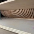
Then start adding the cross battens. These are glued in position. They may be too tight as you want a press fit. So just run the small strips 1/16" x 1/16" through your fingers with some fine sandpaper. Not much. Just enough so the battens fit into the slots. see below. There are seven batten strips and seven laser cut grating strips for three of the hatches. The fourth is made the same way but is much smaller on the fcastle.
When all the strips are glued in position, remove the grating from the jig. Snip off the edges as shown below. Then sand all four edges clean. Try and not distort the perfect square shape. In the photo two sides have the ends snipped off. The smaller hatchway will have fewer battens and more to snip away. Also sand the top surface clean and smooth. Once again try and maintain the proper shape with the round-up. You will know when its all done when the char is cleaned from the laser cut grating strip squares.
The photo below shows the top of the grating and sides all clean and nice and smooth. It makes a nice grating. The holes are 1/16" or 2" on the real ship and perfectly in scale.
You should but dont have to sand the bottom side as well. Here is a look. The battens are clearly less thick than the grating strips and these are pretty close to actual construction methods. Or at least the impression of it.
And almost done...you will see how nice and tight the grating fits in the coaming. Dont over sand the edges and you should test the grating in the coaming as you sand the edges. In fact, the coaming normally has ledges on the port and starboard sides inside the coaming. These create a ledge that the grating sits on so it doesnt fall through. You can add those if you like. But in my case the gratings fit so snug that they were not required. I simply glued the gratings into the coamings making sure the top of the coaming was flush with the grating. I sanded it smooth with some 400 grit paper.
The four corners of the coaming are very sharp at this point. You dont want that. They should be rounded off. But they are only rounded off down to the deck level. That is when you take that same right angle jig and use it.
The jig is the same thickness as the planking. So you can place the coaming into the corner and use a sharp #11 blade to slice away the corner. Slice it down to the top of the jig only. You can make a stop cut at the jig level before slicing off the corner. Then just round off the corner.
Dont slice off too much. Just a little bit to round off each corner.
To finish it off I drilled three holes with a #76 bit. I used 20lb black fishing line to simulate the bolts on the top of the coamings. Three on each side. They cut flush with the top of the coamings with a sharp blade.
All done!!!
-
Chuck got a reaction from KARAVOKIRIS in Sloop Speedwell 1752 by Chuck - Ketch Rigged Sloop - POF - prototype build
What a difference some paint makes. Bulwarks are painted however as usual, I will be applying many more thin coats over the next few weeks as I progress.
Before and after...
-
Chuck got a reaction from KARAVOKIRIS in Sloop Speedwell 1752 by Chuck - Ketch Rigged Sloop - POF - prototype build
Many of you are curious about this photo. Its floating around the forums without an explanation. I brought my Medway Longboat to the New London show last week where it was photographed.. You may not be able to see it right away but yes I changed this Medway English longboat to be an American boat. This model was used in the movie that I worked on last year which I talked about a while back. I changed the flag and the nameplate on the model. They wanted it to be American and have the Character's Name on the model. They were going to slowly pan across it for the movie and wanted Ed Harris' character name very visible etc.
To my Surprise after spending a bunch time with him trying to teach him how to fake being a ship modeler, Ed Harris signed the model. But of course not the base....Black sharpie right across the hull. No fixing that!!! So rather than put the model back to its original English origin and remove the nameplates, I decided to just leave it as is. It will make for a nice conversation piece. The movie is supposed to come out in July I believe....It was about 10 degrees out the day he signed it. The workshop was set up in the garage of the set. I have no idea how they acted as if it wasnt freezing all the time. I suppose that is why he is considered such a great actor.
Starring Ed Harris, Dustan Hoffman, Bill Murray, Gabrielle Union, Jenifer Coolidge, Pete Davidson and a bunch of others you would certainly know. We shall see how the movie turned out!!! At least I have a memento for the wonderful experience.
-
Chuck got a reaction from KARAVOKIRIS in Sloop Speedwell 1752 by Chuck - Ketch Rigged Sloop - POF - prototype build
Bulwark planking has finally been completed. It really wasnt too bad. You just have to keep plugging away and while making careful cuts between those ports. All the cracks, gaps and dents were filled and sanded in preparation for painting.
The second layer of spirketting was added as well to finish off the bulwarks below the ports. The top edge was softened or even rounded off. I dont like to leave a hard edge here. I used a 1/32" strip the same shape and size as the first layer. I took the shapes from the plans because this wide 1/2" strip needs to be tapered like the first layer and shaped before you glue it on. Every model will have slight differences so it will take some time to get it right. Then the top of the sills were very carefully sanded and the cracks filled there as well. I was careful not to sand into the top of the spirketting which would ruin the nice continuous run along its top edge. You can see how bad port sills look now but the surfaces are now smooth and once painted will look really nice.
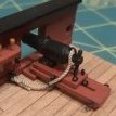
Before I paint however I needed to add the 4 fixed blocks on the inside of the bulwarks. On Winnie, I had used laser cut fixed blocks the same thickness as the planking. You would glue them to the framing before planking and then plank around them. I went a different way this time. I just planked the entire interior bulwarks and then just drilled the fixed blocks through from the outboard side. Then I sanded them clean and reamed them a bit with a round file. To finish off these simulated fixed blocks I took a very small "V" gauge chisel and made a small simulated sheave slot between the two holes. Since the bulwarks will be painted this seemed like the better way to go. You can see the two fixed blocks below at the bow on the starboard side. I used a sharpened pencil to color the sheave to simulate a more appropriate color.
I have also hi-lighted in this photo how I planked the bow inboard. I first glued a 1/4" x 3/64" strip down the inboard side below the bowsprit hole. See the red arrow. This allows me to push the planking strakes up against it which for me makes the process easier and neater. There were two more strakes to add on each side of this to plank the bow inboard. The cracks were filled and it was all sanded smooth for painting.
Here is a photo showing the aft portion of the bulwarks planked and ready for painting as well. Note the two fixed blocks here as well.
The one last thing you might notice is that I did in fact add the margin plank all along the bulwarks. This is 1/4" wide and 3/64" thick. It finishes it off neatly. You dont have to add this yet but I find it easier to paint the bulwarks when I have a nice right angle to paint down to. Hopefully I wont bugger it up and get red paint all over the margin planks. But if you find it easier to paint the bulwarks first without making a mess then fell free to do it that way.
At the bow, the margin planks on each side were cut from a 3/64" thick sheet of yellow cedar. I used the plans and planking template provided. I cut it out and used that paper template as a starting point. After seeing what I needed to adjust for a tight fit, I transferred this shape to the wood sheet and cut it out with a sharp #11 blade. If you look at the photo again you can see my first attempt which I discarded. It didnt fit as nicely as I wanted. So I made more adjustments and cut another. You would be best served to buy a few extra 3/64" thick sheets of Yellow cedar for stuff like this. Every model will be slightly different and you will want to go through this exercise as well for a good fit.
I am ready now for painting....the bulwarks will be carefully painted red over the weekend. Depending on my honey-do list.
-
Chuck got a reaction from KARAVOKIRIS in Syren Ship Model Company News, Updates and Info.....(part 2)
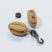
Coming soon. Resin cast barrels.
I have three sizes of cast resin barrels that will soon be available on my site. Currently I have the 11/16" tall and the 1" tall barrels. I am waiting for my casting guy to make the third smaller size. I may even make a fourth smaller size later as well.
I have the two smaller sizes and I am waiting for the last larger size not shown. They are cast in white resin or a light tan like my carvings for the ship models I make. This makes it so much easier to prepare than building my laser cut versions. Those will still be available but these resin versions will give you guys more options. These can be prepared in minutes...
Just clean whatever flashing which is minimal. And remove the small vent hole plugs with a sharp #11 blade.
Then brush on some gel stain...in my case pictured, I used General Finishes Fruitwood gel stain as usual. I have one coat of stain on these. You can add more to deepen the color as you see fit. Then I just used a black sharpie to color the raised iron hoops. You could use any color you want for those as well. You could use a copper leaf pen for example. It isnt difficult....and takes just a few minutes vs. a much longer time to build my laser cut versions.
Each size will be sold two per package.
Its unfortunately too late for me to add these in the hold of Speedwell....but when you need to make a dozen or more barrels for the hold its nice to not have assemble them one at a time.
And Buckets...crates...and other items will soon follow. And whatever else I can possibly think of...please let me know if you guys fancy something in particular.
-
 Chuck got a reaction from cotrecerf in CAFmodel Woodcarving Studio
Really beautiful work Tom. You are making some fantastic progress.
-
 Chuck got a reaction from mtaylor in CAFmodel Woodcarving Studio
Really beautiful work Tom. You are making some fantastic progress.
-
 Chuck got a reaction from Nirvana in CAFmodel Woodcarving Studio
Really beautiful work Tom. You are making some fantastic progress.
-
 Chuck got a reaction from Canute in CAFmodel Woodcarving Studio
Really beautiful work Tom. You are making some fantastic progress.