Supplies of the Ship Modeler's Handbook are running out. Get your copy NOW before they are gone! Click on photo to order.
×

Siegfried
-
Posts
153 -
Joined
-
Last visited
Content Type
Profiles
Forums
Gallery
Events
Everything posted by Siegfried
-
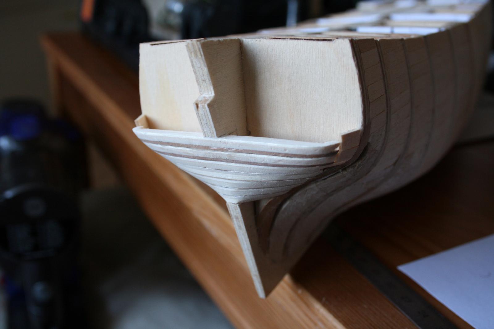
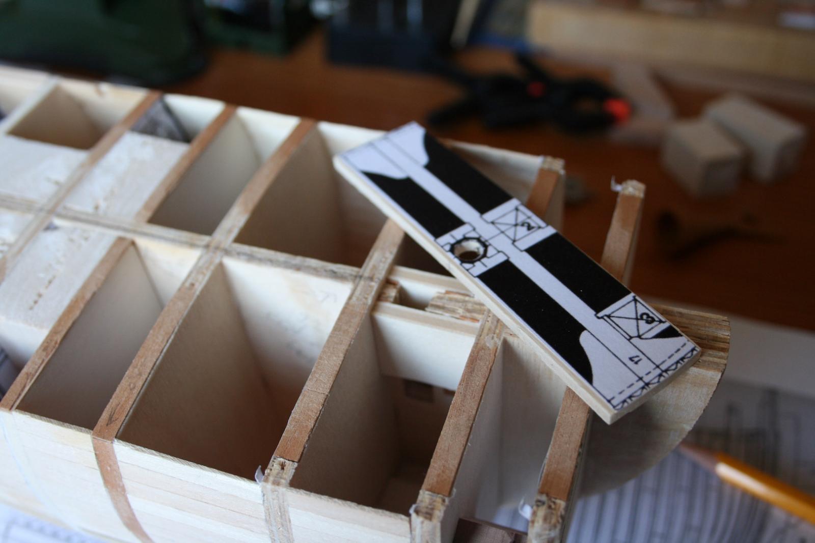
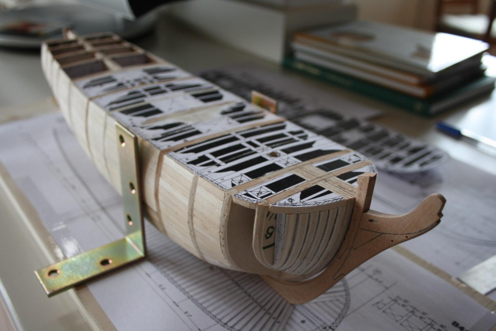
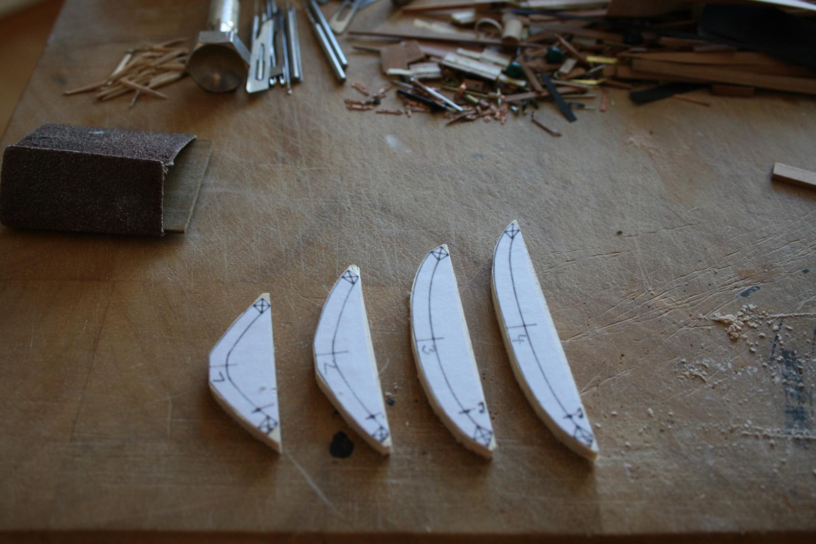
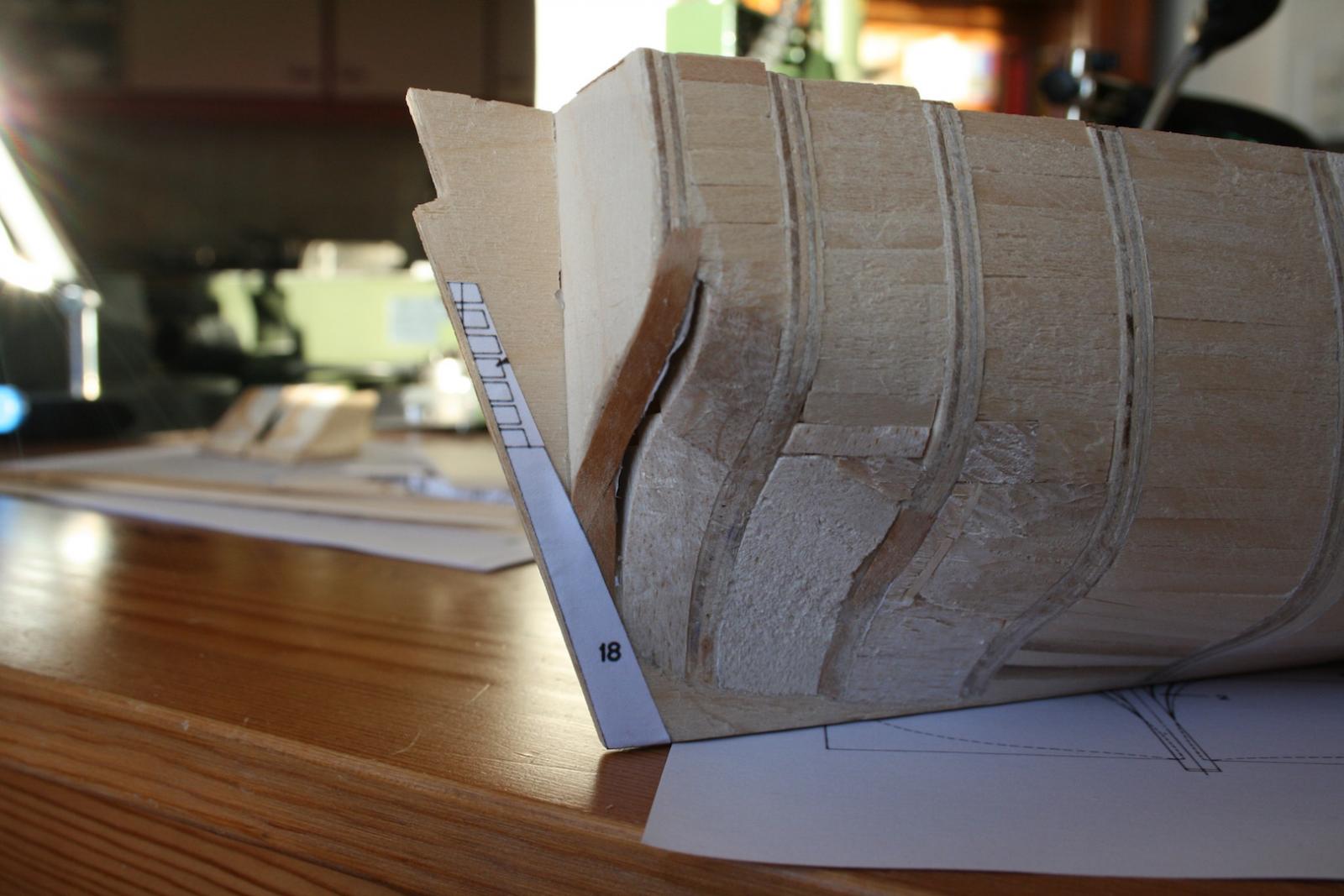
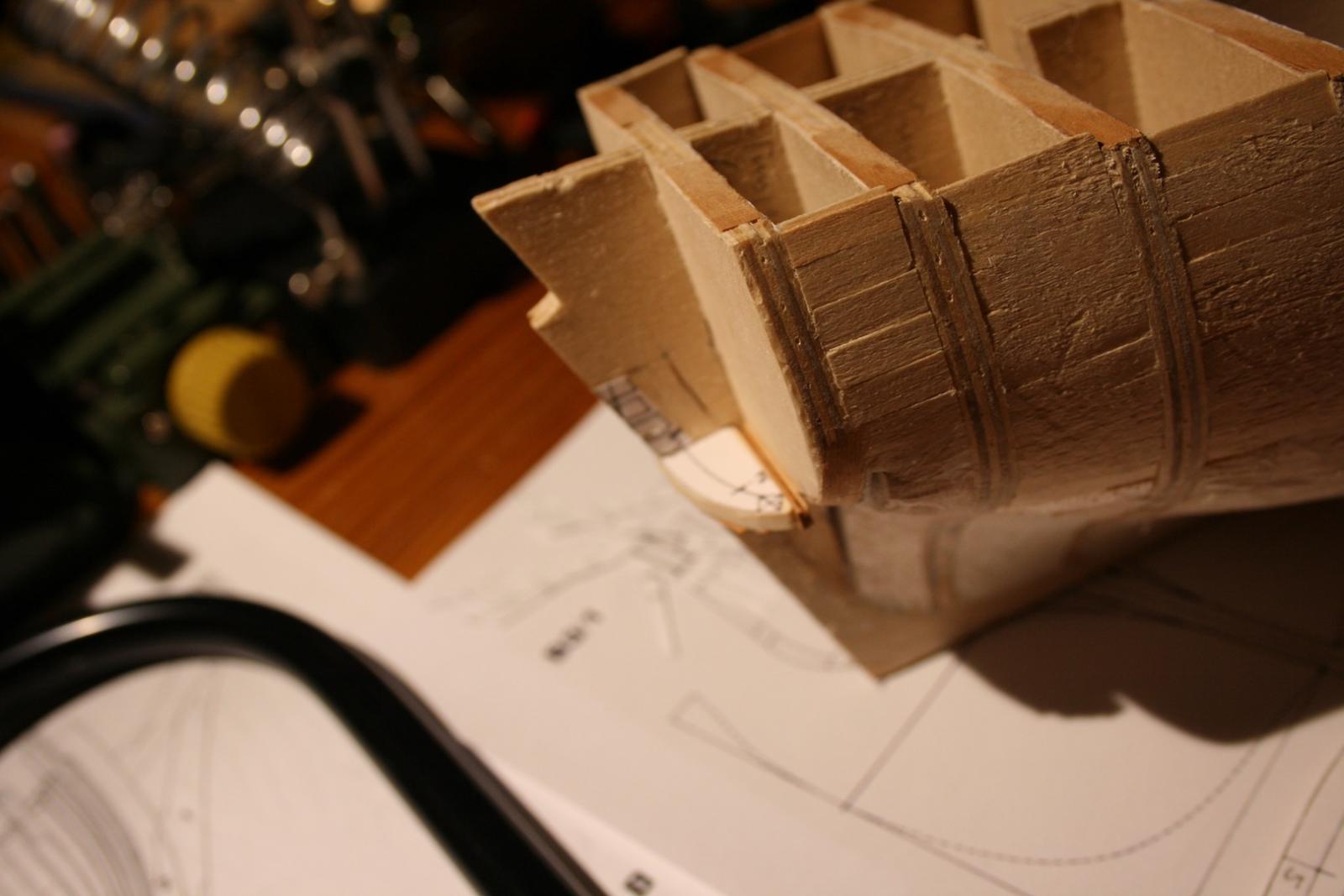
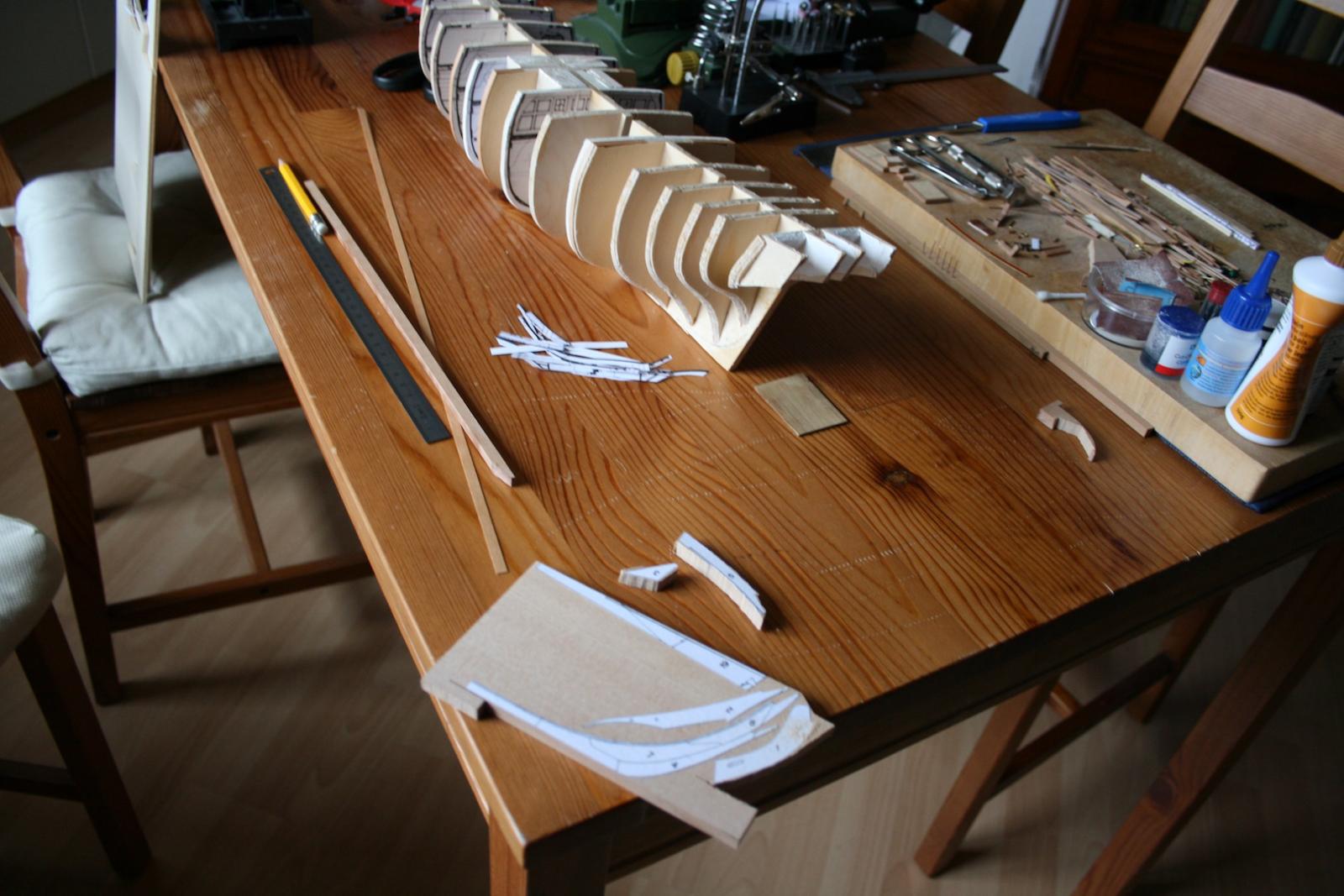
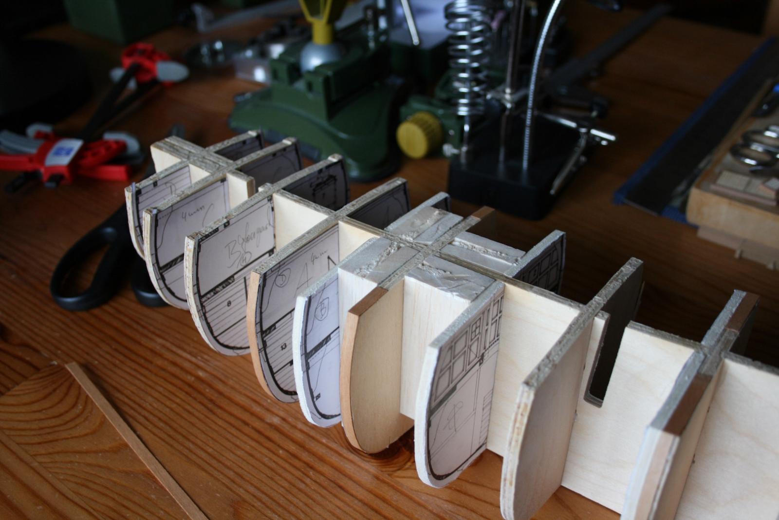
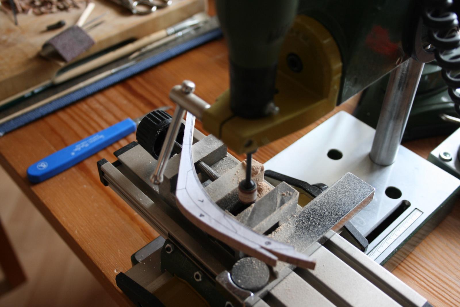
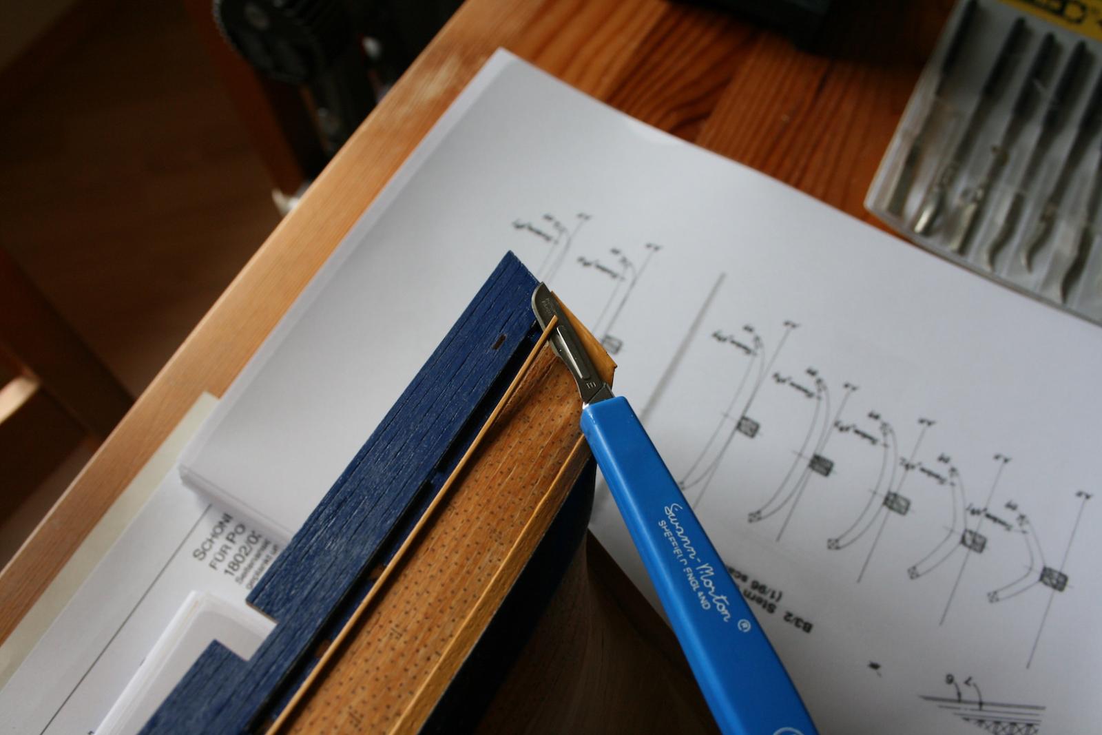
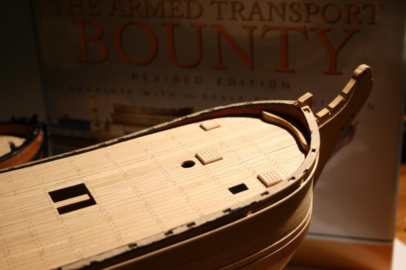
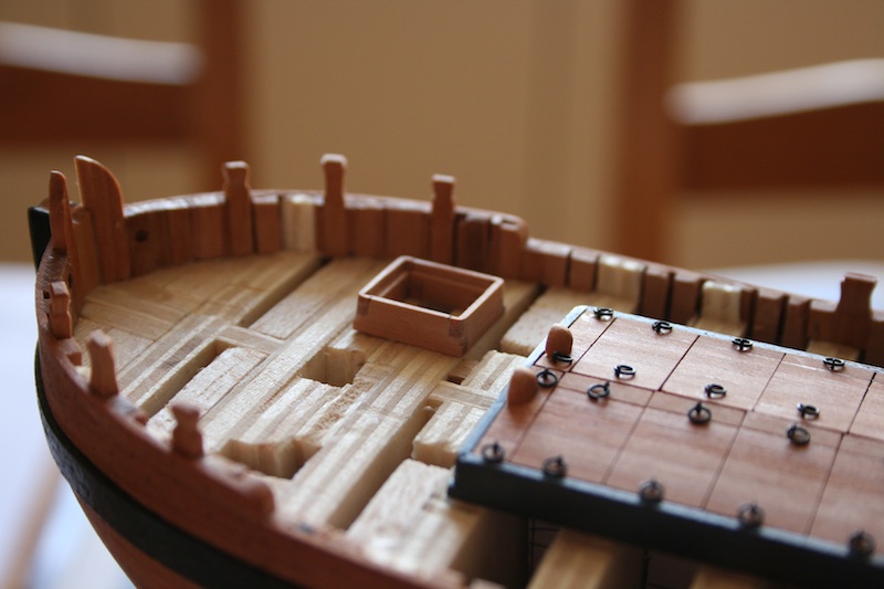
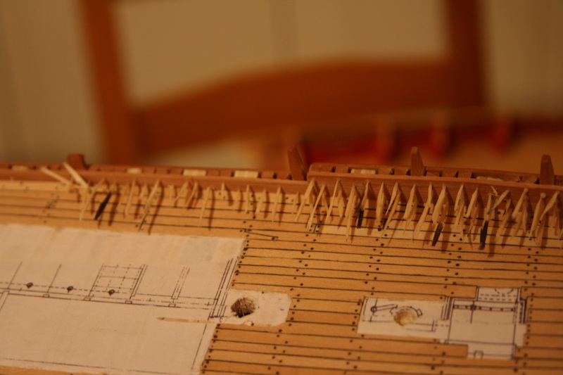
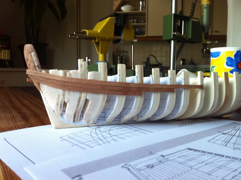
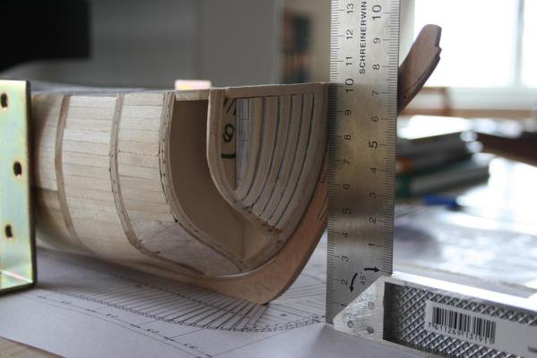
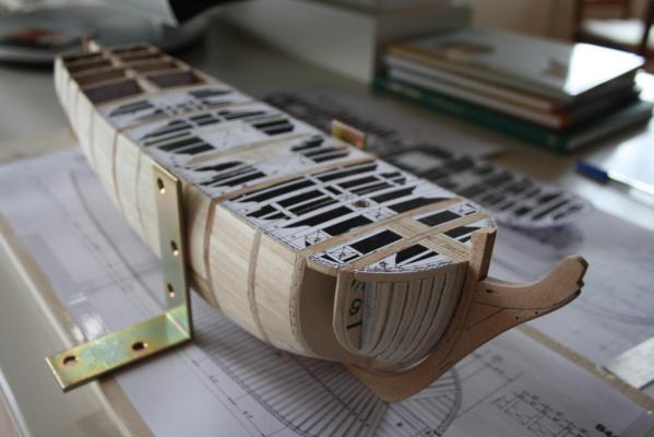
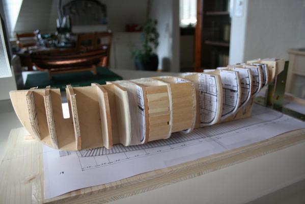
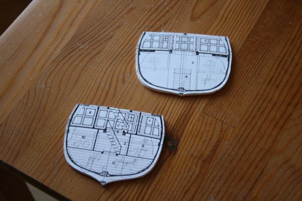
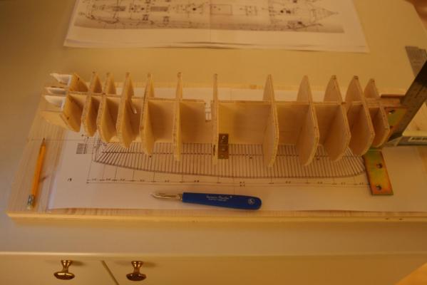
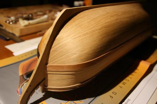
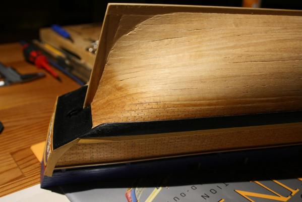
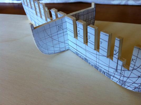
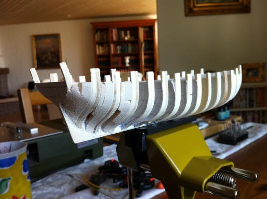
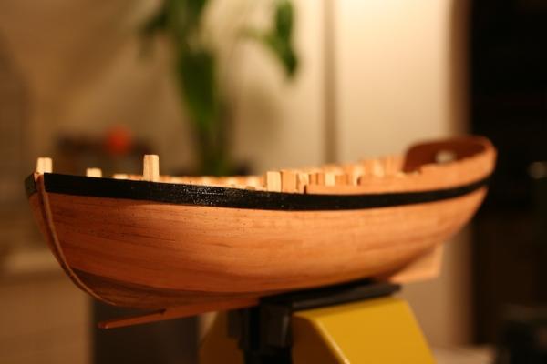
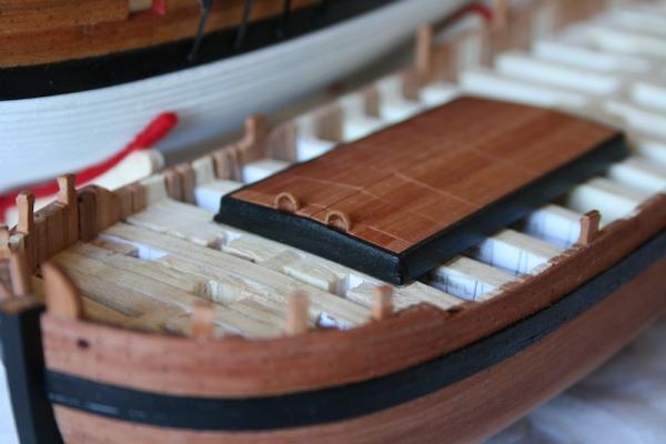
 Hello, The progress is proceeding slowly because of the real job but during the last two weeks I could place all transoms at the stern. After the sanding job the smooth run of the curve is already visible. The transoms are made of 4 mm plywood and I have cut down one of the layers down to 1/8 inch / 3,17 mm, the original size of the transoms in 3/16 scale. By this method the plywood becomes automatically a little bending, which is a perfect effect, as it needs to be bended a little bit. Additionally, I've started with the "frame timbers" at the bow made by 4 mm plywood too. This time I don't had to do any cut off, as the original size of the frames in 3/16 scale is 5/32 or 4 mm. Only the original filler piece of CC's kit, that was already placed on both sides of the stem and needed to be cut carefully from 5 mm down to 4 mm. Between the bow frames I have glued spare wood of 0.8 mm thickness to keep the right distance between the frames. Frames of Bounty where of 10 inch thickness an 2 inch distance between the frames. In 1:64 scale it is exactly 3/16 inch or 4.76 mm respectively 5/32 inch for the frame and 1/32 inch between the frames. Furthermore I could finish the "deck beams" from stern to the aft section of the main mast. Here I used a printout of the deck beam section from AOTS Bounty, glued it piecewise on 4 mm ply wood, cut the ply wood again down to 3 mm to get again the mentioned self-bending effect, which makes it easier to bring the "beams" into the right run of the deck. Therefore I had to cut the centrepiece between the bulkheads step by step down. Abaft the main mast I stopped to continue the work as I am thinking about constructing the full main cabin showing all plant pots and breadfruits. It might be a funny idea to show the Bounty in a diorama right at the moment of the mutiny with open stern windows and angry seaman who throw the plants behind Bligh's barque. Meanwhile I waiting for the timbers I have ordered at Lumberyard and Crowntimberyard. Swiss Pear is for the planks, dead woods and wales. Holly is for the deck. As I had a little time I worked on an Excel file to calculate all masts, yards, planks and wooden pieces down to 3/16 scale in metric as well as in imperial measure. For everyone who wants to build that ship in the same scale it might be useful to order all necessary strips and sheets with the correct thickness. Cheers, Daniel
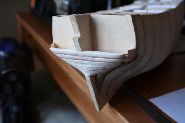

-
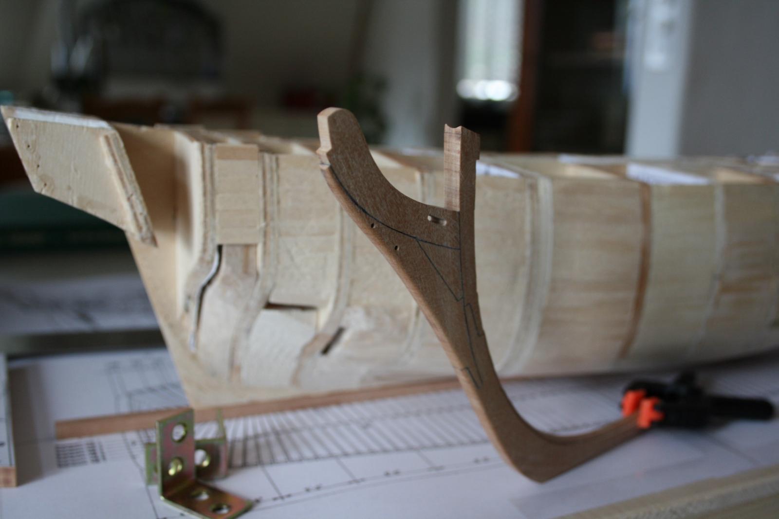
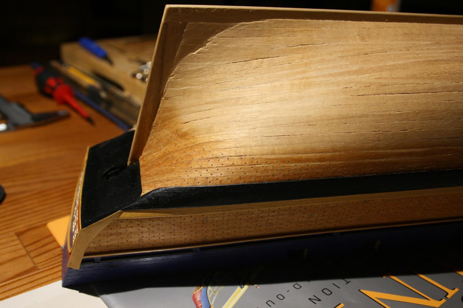
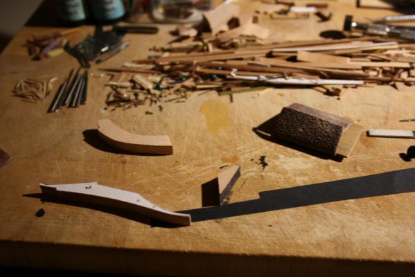
Hello, This week I had a little time to work on the keel rabbit and on the transoms. Cheers, Daniel


-
It's a great looking model. It assumes to be of a large scale. What exactly are the measures? Daniel
-
Hello, Meanwhile I could made some progress on the hull and finished the work on the stem by sanding down and rounding the fore part and cutting the rabbit. Next I have to work on the stern constructions and the transoms. Additionally, I have changed the mast position approx 3/16" respectively 1ft forward. CC has shift it aft to an acceptable range as the lower end of the main mast would directly go through the cross section 1. I am sure they made the decision to keep the kit as simple as well as practicable, even to rookies in this wonderful hobby. Have a nice Sunday, Daniel


-
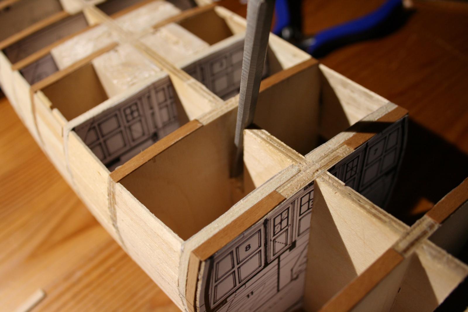
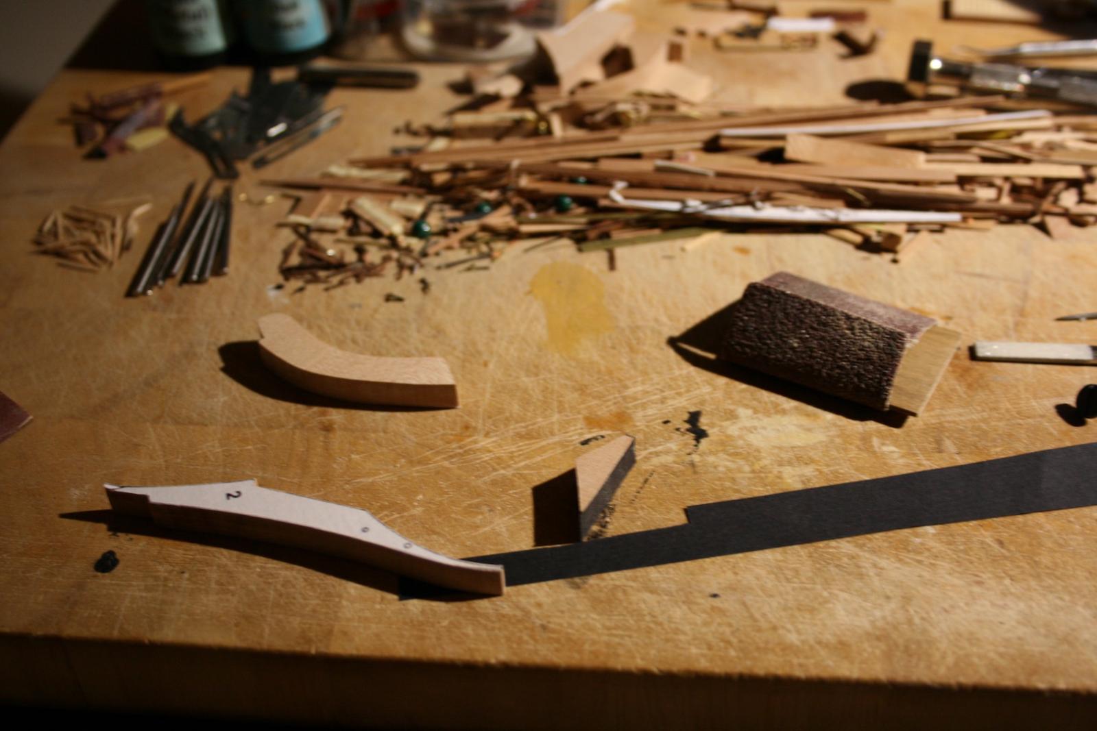
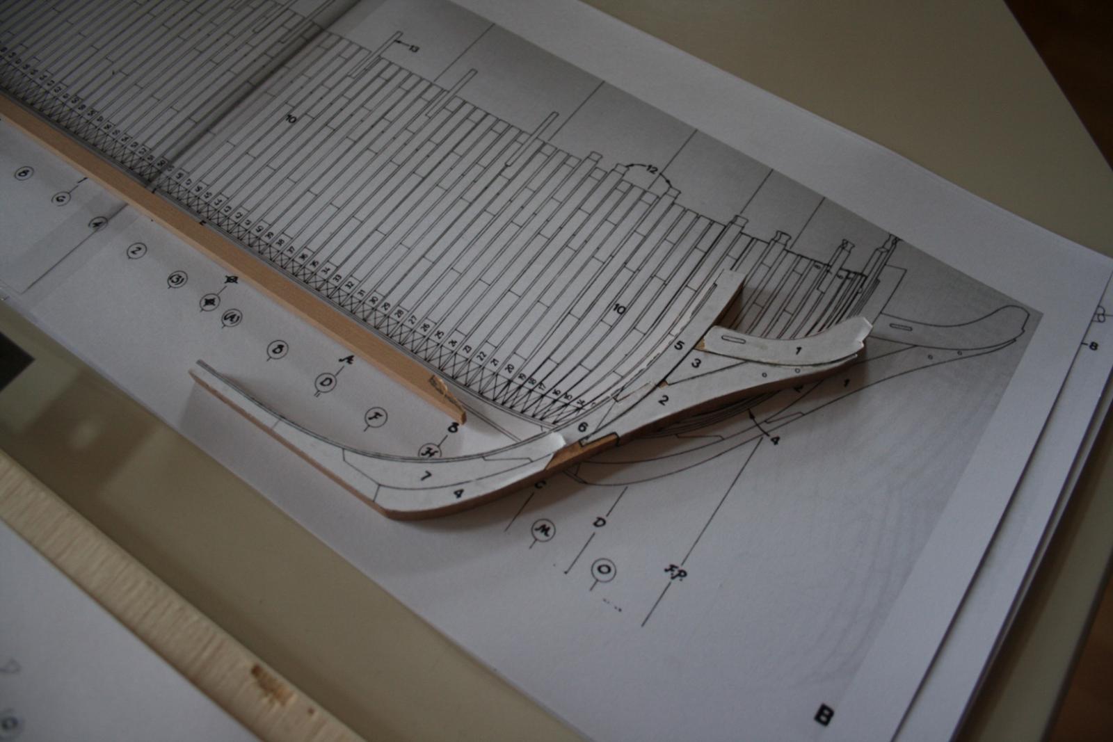
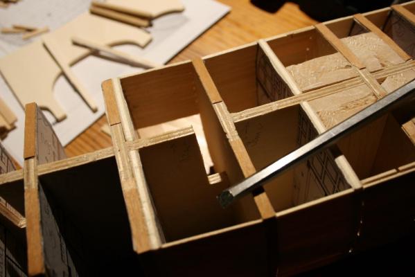
Hello, At least I have finished the work on the bulkheads except the transoms at the stern. First I have glued in the cross sections from AOTS and reshaped the frame by cutting and filling. Further more I placed three additional bulkheads at the sections B, 2 and 10. At this stage I have to correct myself. The positions of the frames in Caldercrafts kit might be exact. Nevertheless, for someone who wants to use the drawings of McKay's book has to be aware about the proper scale of the cross sections. Most of the draughts in the book are in 1:96 scale. However, especially the three cross sections showing the fore, main and mizzen mast doesn't fit exactly to the rest of the drawings and appears to small. This turns out when you place the sawed frames on the centrepiece. Especially the hight between lower edge of the keelson to the upper edge of the deck beams is to low, and doesn't fit to the hight oft the other frames with a gab of up to 2-3 mm. Despite this the wide of those frames is perfect. I've go confused and measured the remained centrepiece of the kit. I have to say that it is of a very exact size comparing to the NMM draughts. Well done by Caldercraft. Therefore I've used the upper edge of the centrepiece as mark for the hight of all deck beams regardless of the hight shown on the printed cross sections. To stabilise the frame construction I am now on to fill the frames with remained spare lime wood. It will be later on a kind of 1st planking and offers a perfect surface to mark the sheers and wales. Additionally, I have scratch build the keel, stem and stern made of pear. Too, it ist important to compare the sizes of the printed side view of the frames, keel and dead wood as well as of the inboard plan. It is not of the same size. First I thought it was a gap because of the print job but after measuring the drawings directly in the book, the gap still remains. The inboard plan ist the most correct one comparing to the NMM drawings, the side view of the frames is to small. Foolishly this was the template I've used for to cut out the timbers for the stem. But fortunately I could compensate the gap by caulking the timbers. This very thin layer between the timbers was enough to enlarge the size of the stem. Generally, as it might known, it is important to sand down the edges of the timbers to avoid exactly this effect. At this time it was welcome. In the end ship building is all about mathematics, physics and geometry. Cheers, Daniel

-
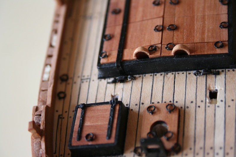
Bravo, I'm loving your details on the ship. Daniel
-
Hello Mark, A wonderful inspiration. Thank you for sharing your technique of glazing the windows. Something I will test later on too. Daniel
-
Now I am on to make additional bulkheads, repair and reshape the kits bulkhead to fit the proper dimensions of the draughts and to make the keel and stern/stem timbers. Cheers, Daniel


-
Hello Antony, That's easy. Just go on NMM / Royal Museums Greenwich homepage and make an order of the plan Nr ZAZ6665 (lines and sheer plan) and of ZAZ6668 (upper deck plan including plant storage). Go to rmg.co.uk, then to national maritim museum, then to shop, then to ship plan prints& scanning and follow the order. There you can have a look on the most ship plans available at NMM. Additionally you can have also the drawings of the original Bethia taken from the dock soon after the purchase of her by the admiralty. I have ordered my plan in 1:36 scale. But in origin it is in 1:48 scale. Alternatively you can order the copies as picture on disk. Then it might be easy to work with it directly in a CAD or any photo software. Cheers, Daniel
-
Wonderful carving job you have done there, Fam. It's looking pretty good. Daniel
-
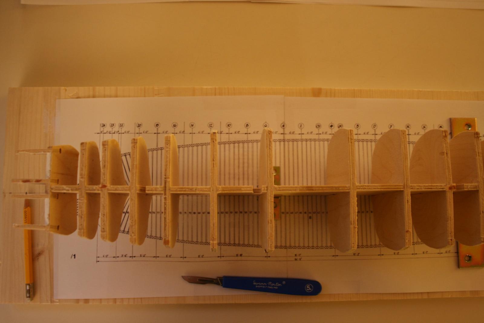
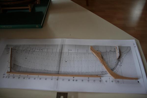
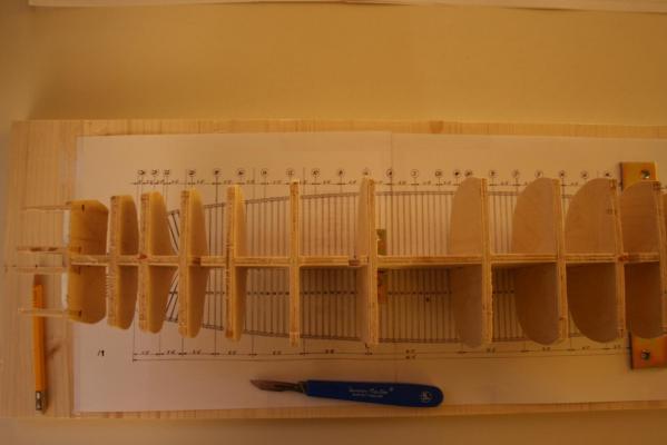
Hello Mark, Indeed, all the bulkheads get a sanding and a reshape. Furthermore, I have to do some additional bulkheads. As you might see on the pictures below, the bulkheads in Caldercrafts kit aren't placed at the proper position. If I compare the frame position of the drawings with the actual position of the bulkheads on the centrepiece, most of the bulkheads are shifted up to 4-5 mm aft. That wasn't my mistake, as the laser cut job on the notches to house the supplied bulkheads was done by Caldercraft. No wonder why the bends of the planks had no smooth run. Because of the size of the vessel I will use the first time a building slip with the frame layout bonded onto the board. With this method I want to place the new self made bulkheads on the proper position. That means I have to reassemble the bulkheads from he centrepiece and to prove the shape of those. Than I have to marke the single frames by a pencil on the centrepiece and to cut in additional notches to house the new bulkheads. Also I have to widen the notches for the changed mast positions and yet to cut the notches for the old bulkheads at the right place/frame. A lot to do and actually a start from the very beginning on. Cheers, Daniel
-
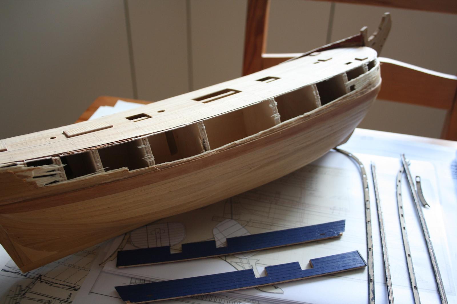
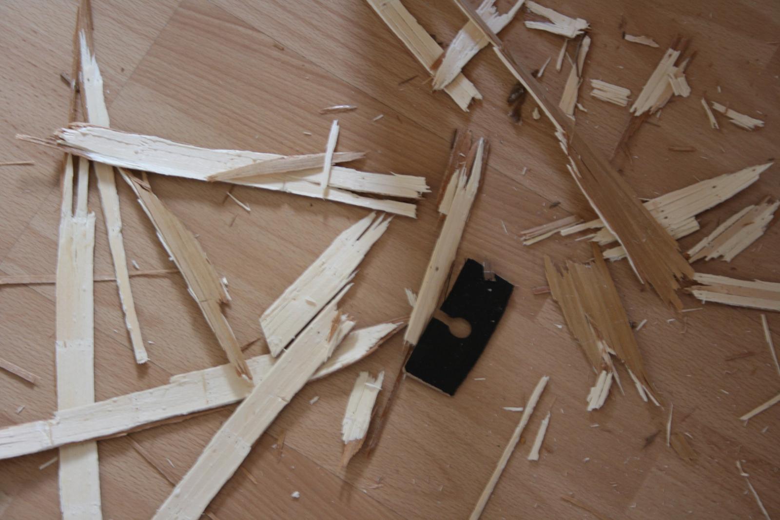
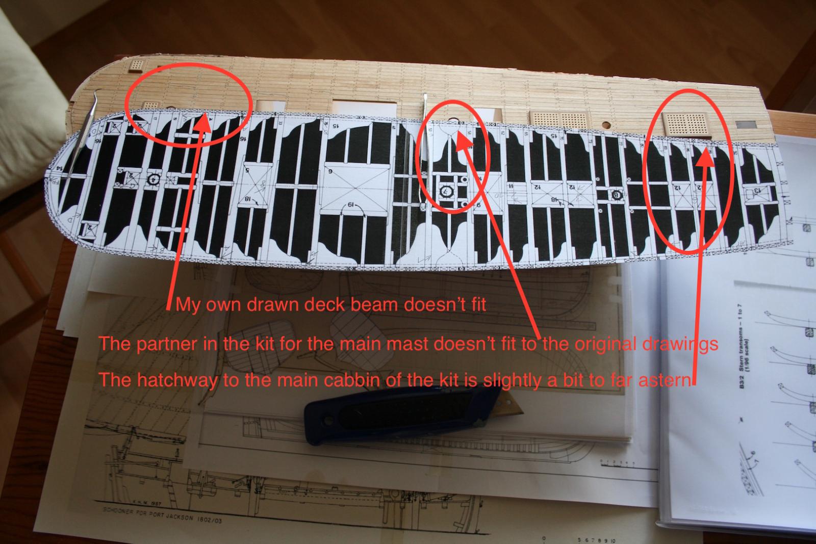
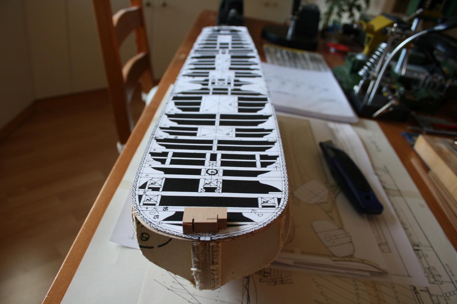
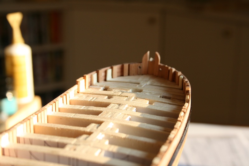
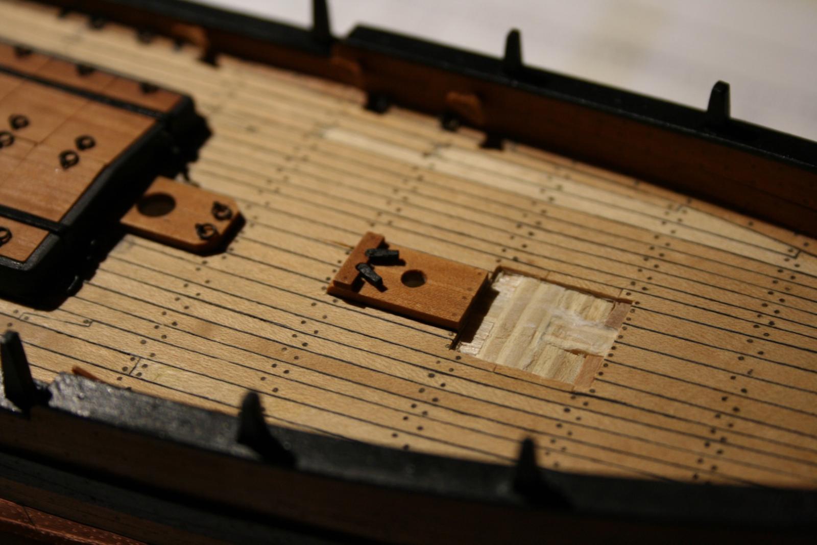
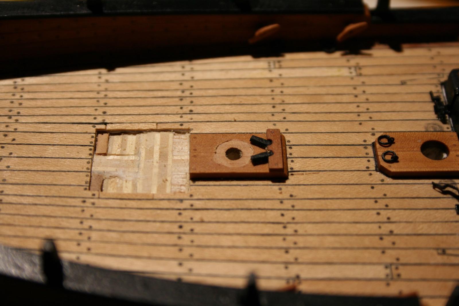
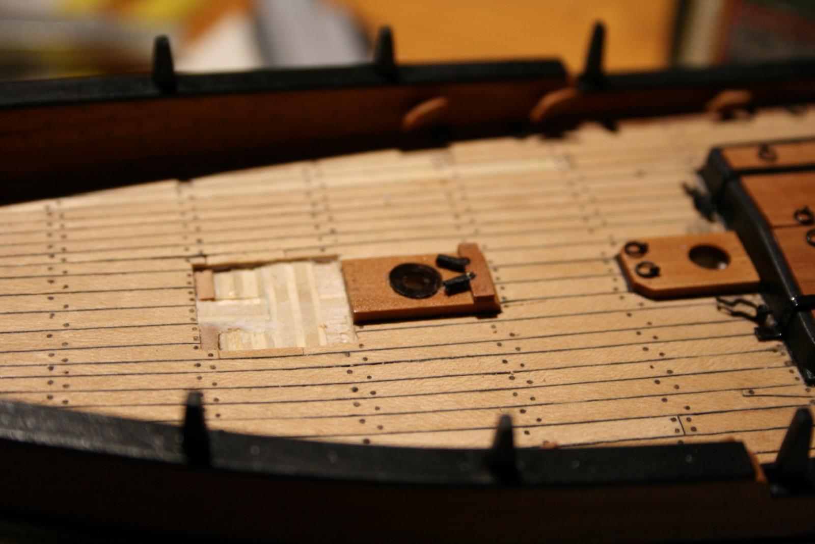
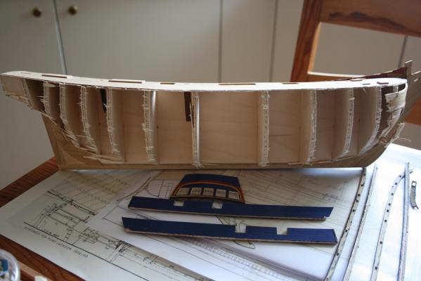
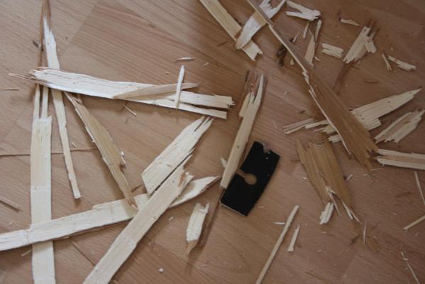
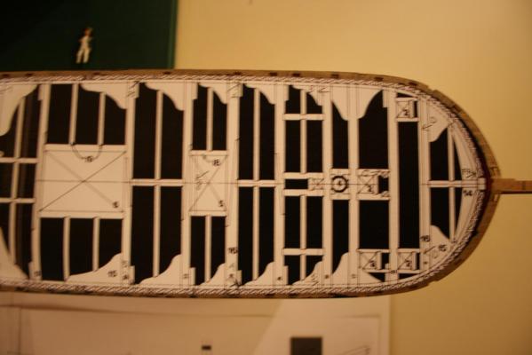
Hello Antony, Thank you for your interest. It's going to be a challenging project. Ladies and gentlemen, may I introduce you HMS Bulkhead :-) I started today to reassembly the ships hull carefully and protected the stern structure. Maybe I can use it later on again. It's a pity to destroy the old work. When I lay the deck beam over the deck plate from Calderkraft's kit there are some differences recognisable. Most of the deck layout fits to the original drawings except the mast partner for the main mast, the mast partner for the mizzen and the hatchway down to the captains cabin. It is slightly a bit settled to far astern. On the second picture is clearly shown the major mistake Caldercraft did with its kit. My deck beam drawing does exactly fit to Caldercraft's deck plate. The problem is , I have let the frames on the side of the drawings to see the proper run of the hull planks in proportion to the deck. That means Caldercraft simply forgot to subtract the wide of the lime wood of the first planking from the kits bulkhead and deck plate. That's why the ship finally is in all dimensions to large if you follow the kit's building manual. As result it does mean, when someone wants to use the general excellent quality of Caldercraft's Bounty kit he has to be aware to disclaim the first planking with the lime wood. Despite this he should fill the space between the bulkheads wit balsa and then plank over it directly with walnut (supplied with the kit) are any other wood of his convenience. I am going to use Swiss pear as usual. Additionally, the technique of filling the space between the frames offers to get awarded by a better shape of the hull. These shall be the last words about the original kit as further comparison is not possible. Next I have to reassemble the bulkheads and will add the hull structure by additional bulkheads taken from the original drawings. Cheers, Daniel


-
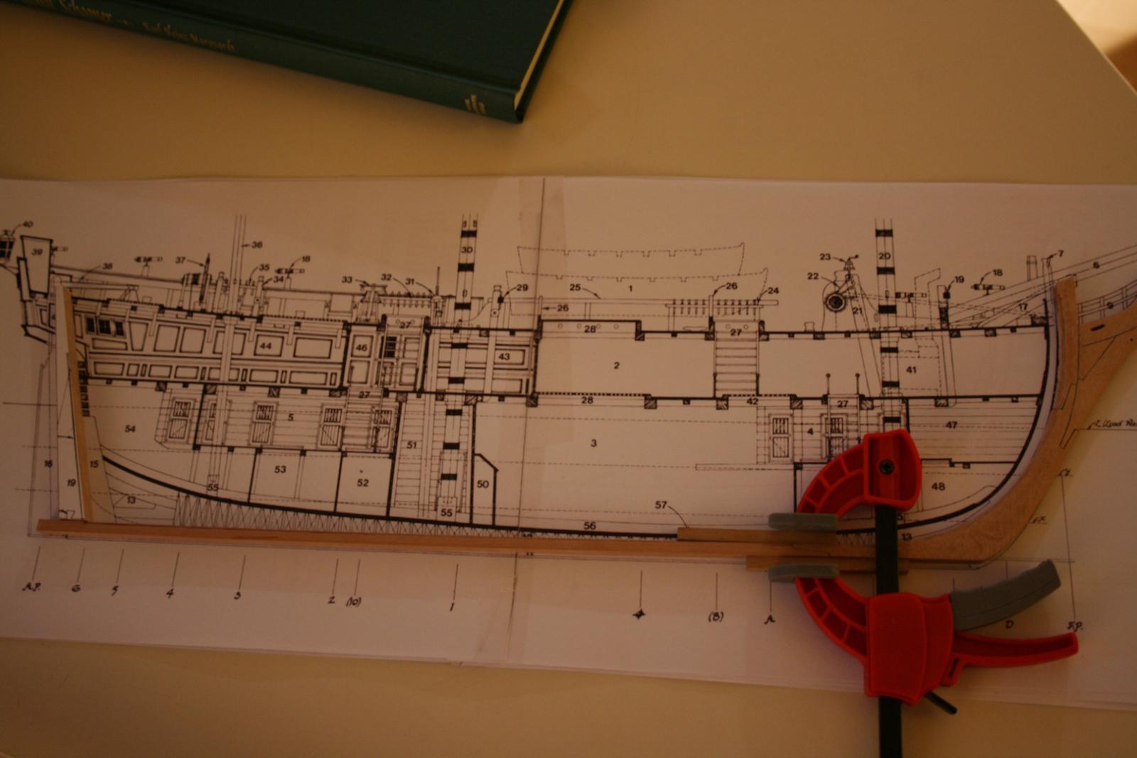
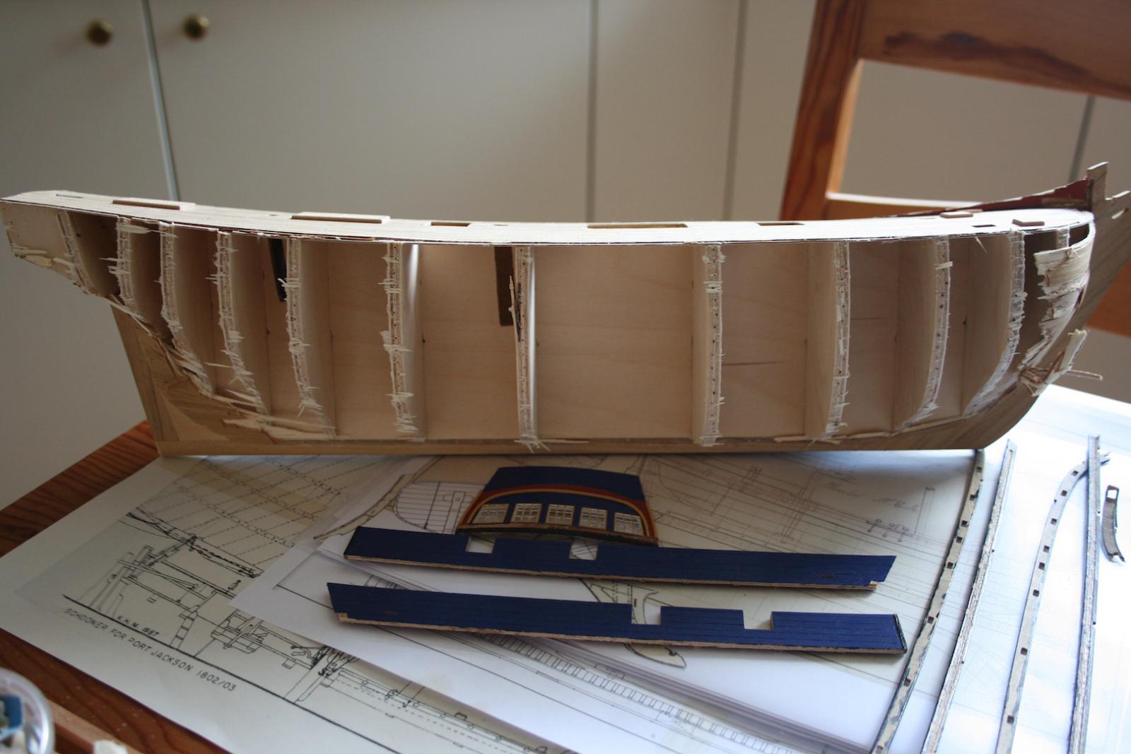
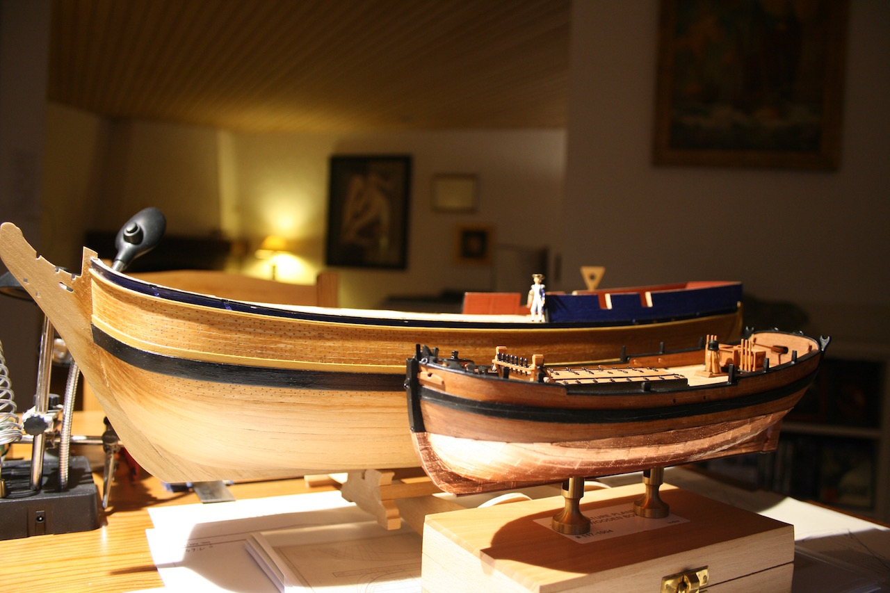
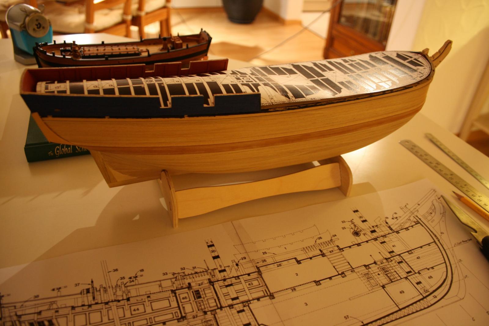
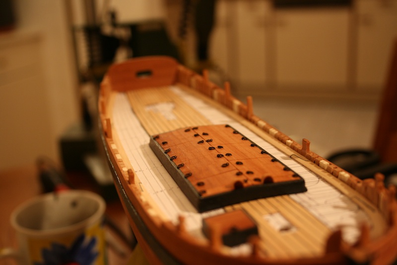
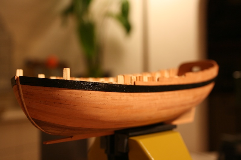
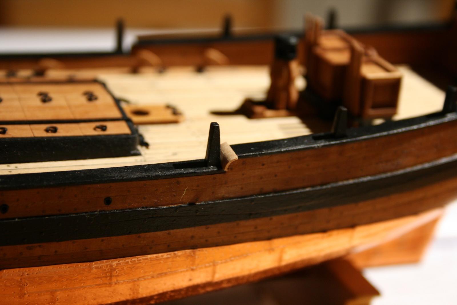
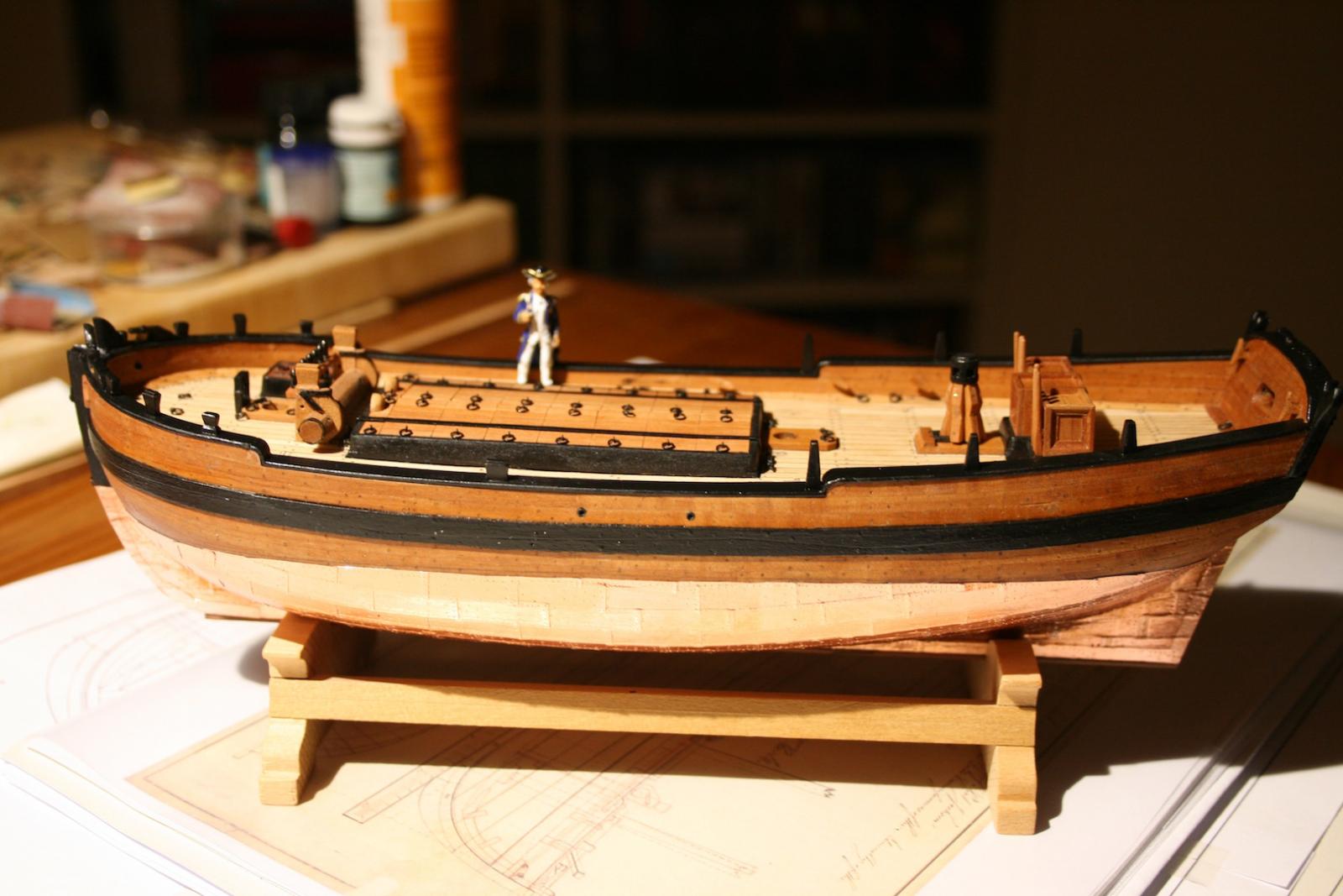
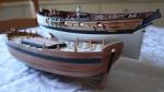
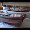
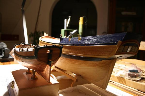
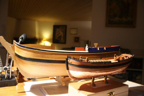
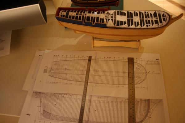
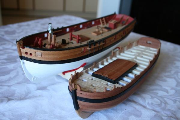
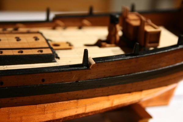
Hello all together out there, About ten years ago I've purchased Caldercraft's Bounty kit but stopped the build, my first build log on MSW I, soon after the finish of the second planking. The reason that led to this decision was simple. Meanwhile I've got John McKays book about the Bounty from the Anatomy of a Ship series as well as a copy of the original drawings made on behalf the Admiralty 1787 soon after the purchase of the Bethia. The drawings have had a lot of alterations to modify the ship for survey service in Her Majesty Service that ends up in the famous voyage and the mutiny in the years 1788/1789. A view on McKays drawings and on the NMM's drawings brought to light, that the dimensions of the spares and parts in the kit doesn't really fit and where oversized. Especially the breadth doesn't fit and seems to be 1 foot 8 inch too wide. In the end, I've got frustrated and began another build, the HMC Sherbourne, but this is another story. Unlike the common knowledge about Bligh, Christian and the mutiny, burned in our minds by well entertaining but less historical movie pictures, we do know nowadays that Bligh was not that despot as shown in the movies. Actually, he was one of the best navigators after Cook and a commander with foresight. 2 years later he fulfilled his order to bring breadfruit plants to the West Indies on a second voyage (a less known fact), became captain, fought at the battle of Copenhagen close to Nelson, was honoured by Nelson to be a very brave and proper commander in the battle and became in 1806 governor of New South Wales. This fact does close the circle form the Bounty to my another scratch build, the Schooner for Port Jackson. These ship sailed during the government of Bligh who became Vice Admiral. It is known today that Edward Edwards, commander of the HMS Pandora cumulated all the granted characteristics told about Bligh. By the way, among his remarkable voyage of 3,618 nautical miles (6,701 km) to Timor in Bounty's 23ft launch in company with his loyal men he survived two another mutinies. Two of his fellows on this voyage did the same trip again in an open boat in 1791 after HMS Pandora wrecked in Torres Street. Thus sailed with captain Edwards to catch the mutineers. To the restart of my build of the Bounty; Over the years the kit is gone and my first try get dusty in the bookshelf. I going to preserve her from an inglorious fate and wanna build her back to the bulkheads first and will start a second scratch build project. Meanwhile I have scaled up the drawings from McKays book to my preferred 1:64 scale. She was my first wooden shipbuild and after the scratch building experience with my Sherbourne and my Schooner for Port Jackson I am less happy with the obvious mistakes I did, especially on the curves at the bow and the stern, as well as with the (minor) incorrectness of the kit. As told, the breadth appears 1 foot 8 inch to large (8 mm in 1:64 scale), too, the bulwark astern is approx 10 inch (4 mm in 1:64 scale) to high. Attached you find some pictures about the current status of the Bounty. It is interesting to compare the 50ft Schooner for Port Jackson with the size of the 89ft Bounty. Both are made of the same scale. Cheers, Daniel


-
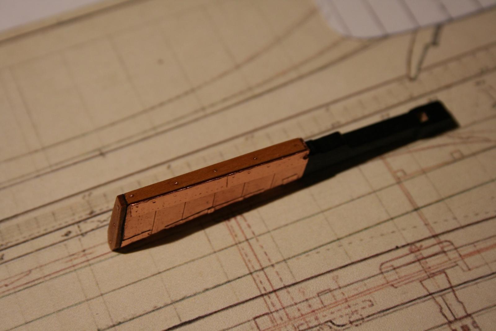
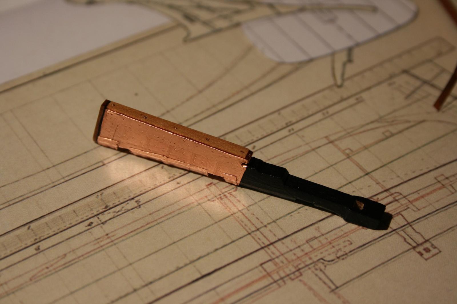
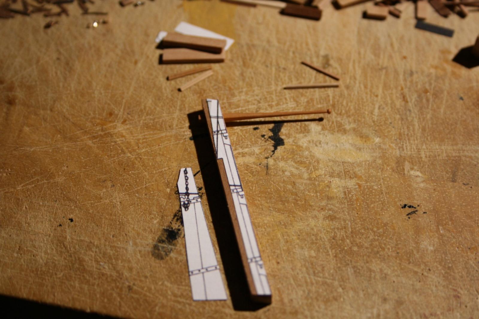
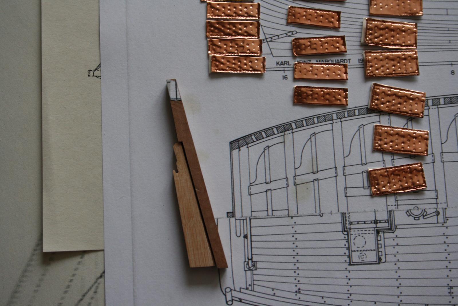
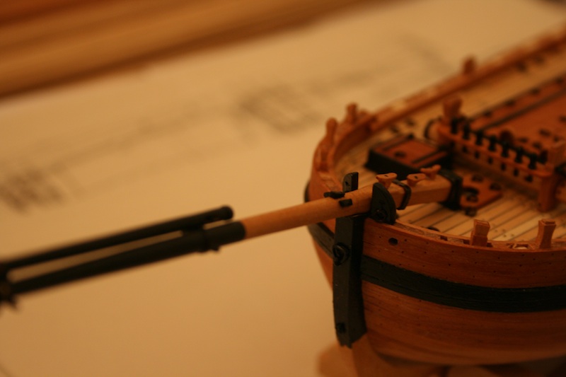
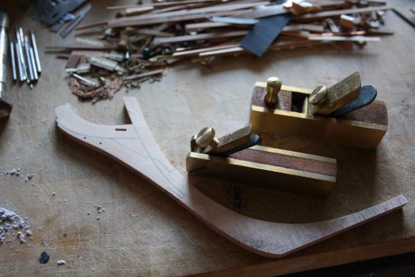
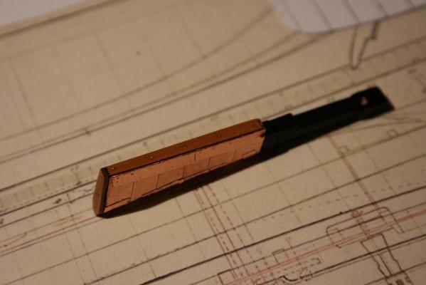
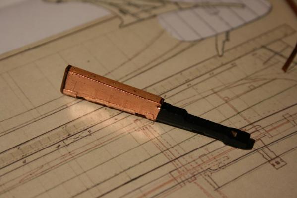
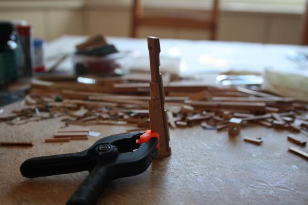
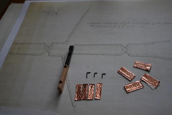
Hello, and so is the rudder looking after copper sheathing and some paint work. The hinges are not finished yet. To copper the areas behind the hinges was a very fiddle job as well as the part with the notch on the backside. I have researched all my monographes, plans and anatomies. On all other ship plans the notch on the rudder was marked over the waterline and therefore generally not coppered. However, on NMM original drawings of the Schooner for Port Jackson the notch is clearly visible under the waterline. The first time I saw that and I have realised that tiny little detail just today. Does someone know another examples? Marquardt has drawn in his plans an additional batten on the backside thats is not drawn on the original plans. I do assume it is something like a false keel with protective effect. Best, Daniel

-
A wonderful and rare project. I am keen to see more. Daniel
- 641 replies
-
- 3
-

-
- greenwich hospital
- barge
- (and 1 more)
-
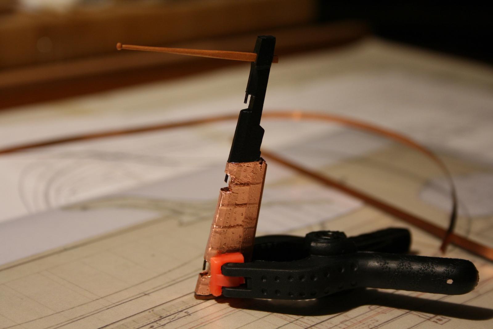
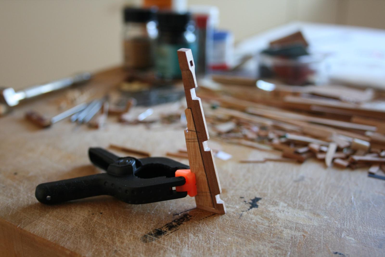
Hello, thank you very much for your Likes. Here are some pictures about the further progress on the rudder. Next I have to cover the underwater part with copper sheaths and to assemble the hinges made of copper too. Best, Daniel

-
Wish you a good start with your revitalised frigate. I am sure to speak for all of us when I am kindly ask you for another pictures of you build. By the way, the oil paint you have posted ist interesting. It seems so that the English frigate and the French one in the background have red-painted gun strips. Best, Daniel
-
Hello Siggi, The quality of the paintings you made at the stern as well the clean and crisp work generally is inspiring. Do you plan to build the rest of the vessel too as a three-piece model? Cheers, Daniel
-
Attached you will find some selected pictures from the very beginning of the build posted on the MSW I three years ago. Daniel


-
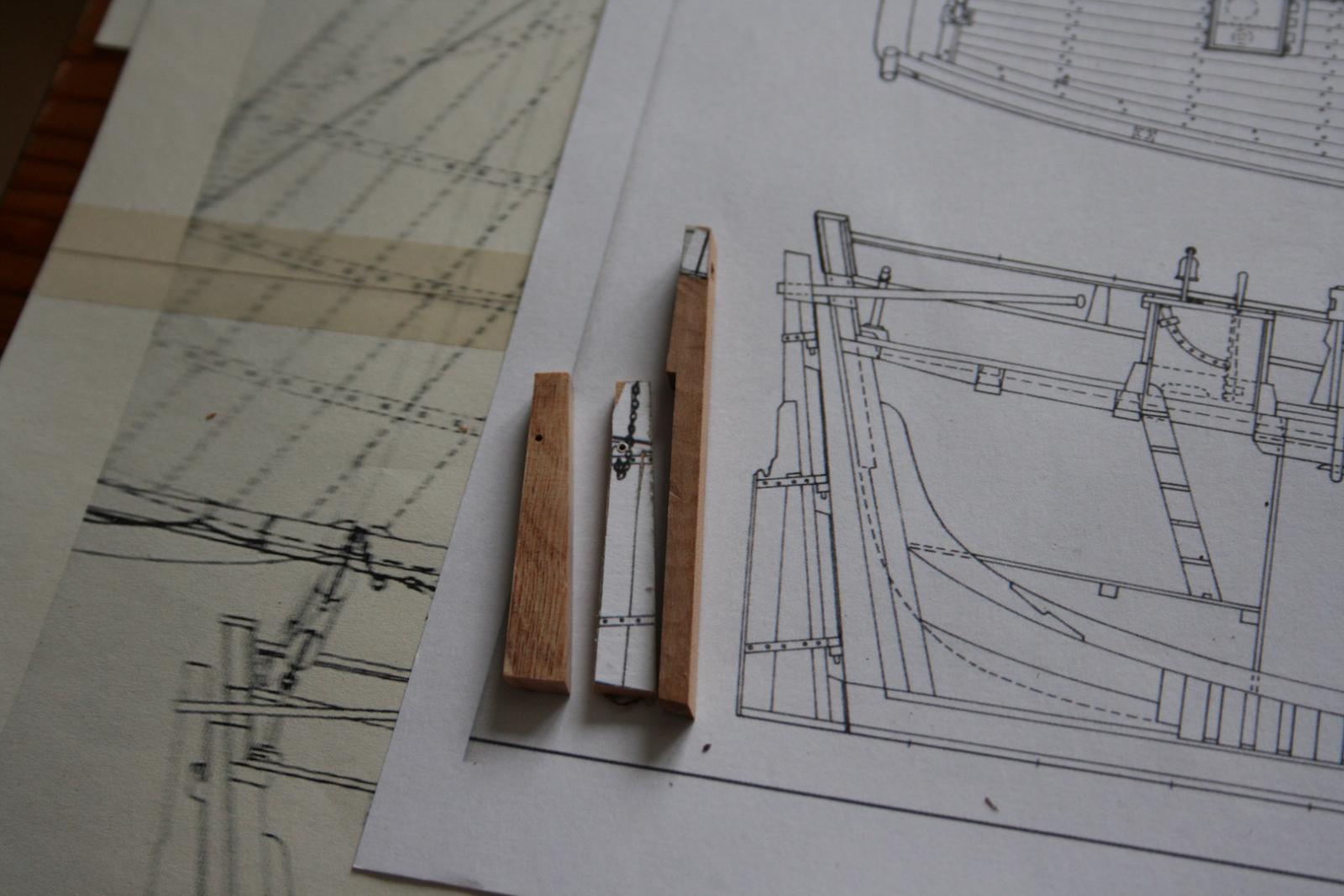
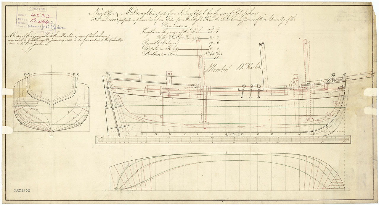
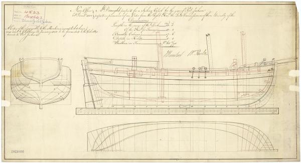
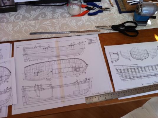
Hello Steve, Thank you very much for the correction regarding the bank note. My fault. I have never been in Australia. It seems so that ms Reibey was a tough lady, especially under the circumstances of the early years in the Australian colonies. My build is completely scratch build following the draughts of Karl Heinz Marquardt in his book Global Schooners. I too use copies of the original NMM draughts ZAZ6101 (frames and deck layout), ZAZ6100 (sheer plan) and ZAZ6102 (middle & lower pintle brace of the rudder). The scale of the build is 1:64. As I do remember right, the scale of Modellers' Shipyard's kit is 1:50. Isn't it? Best, Daniel
-
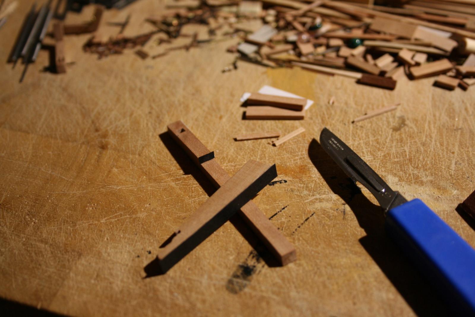
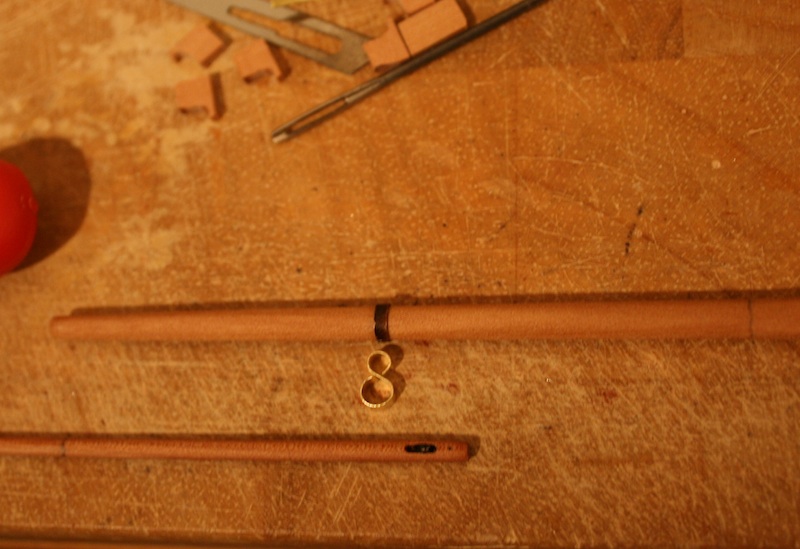
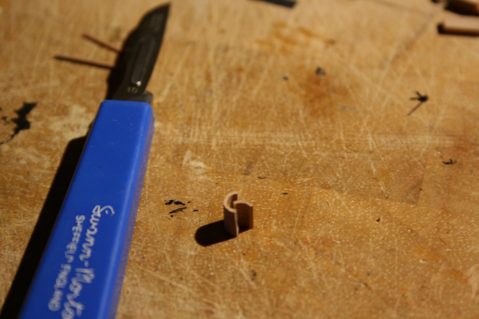
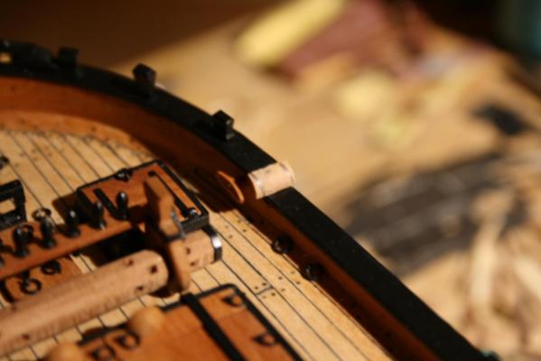
Hello out there, Thanks you all very much for your Likes. Today I've finished the bended parts of the driftrail, finally. I milled a tube made of Swiss pear with an inner diameter of 4 mm and a thickness of 1 mm. next I've quartered it carefully and shaped the pieces to the run of the rail. Daniel


-
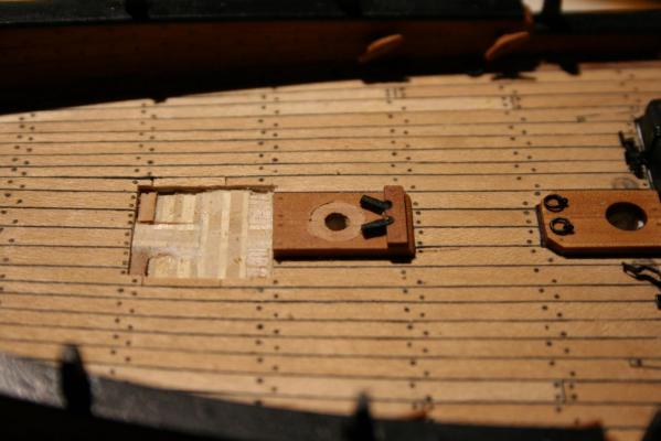
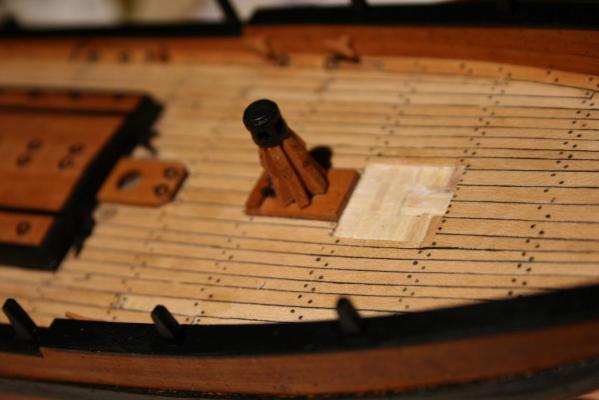
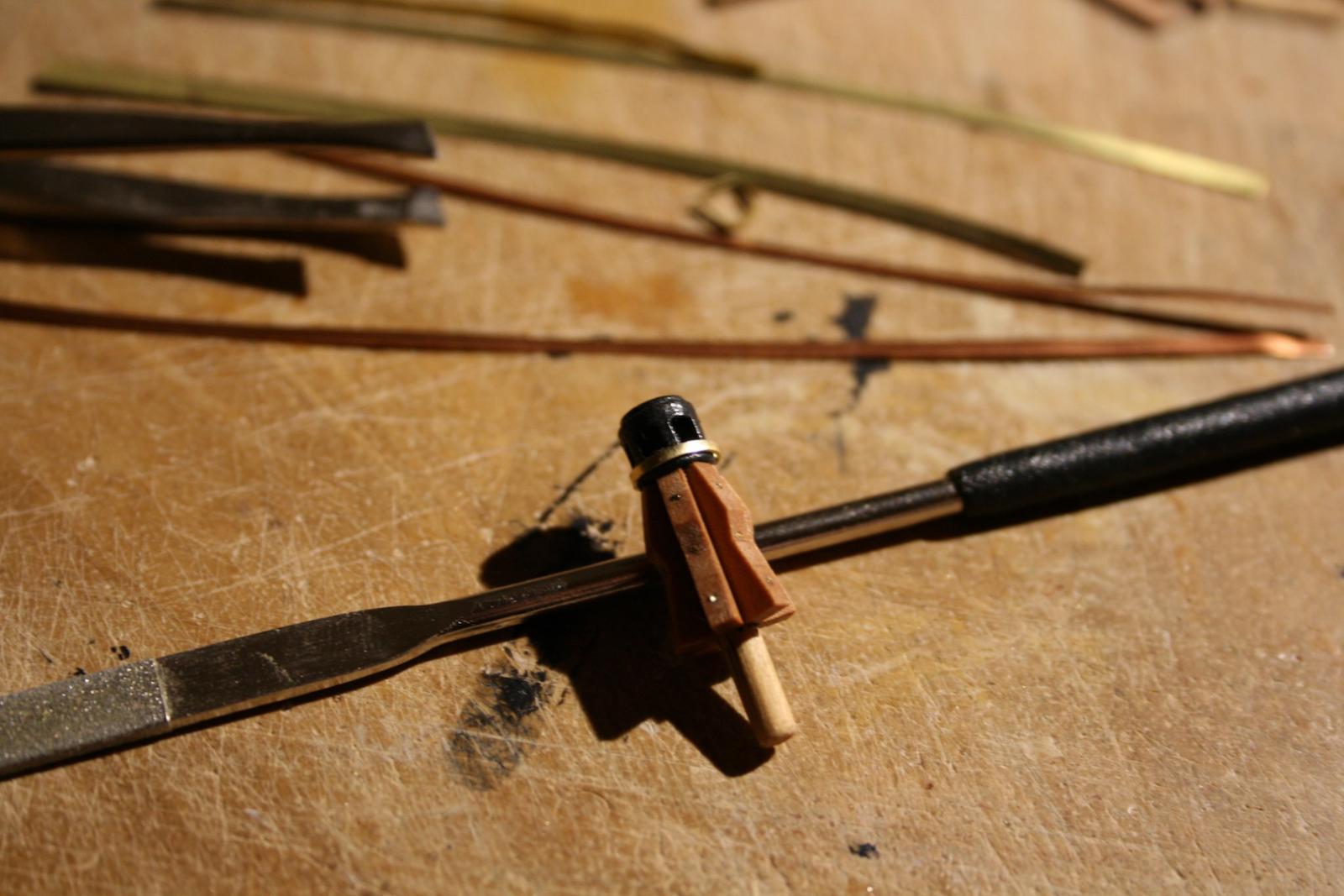
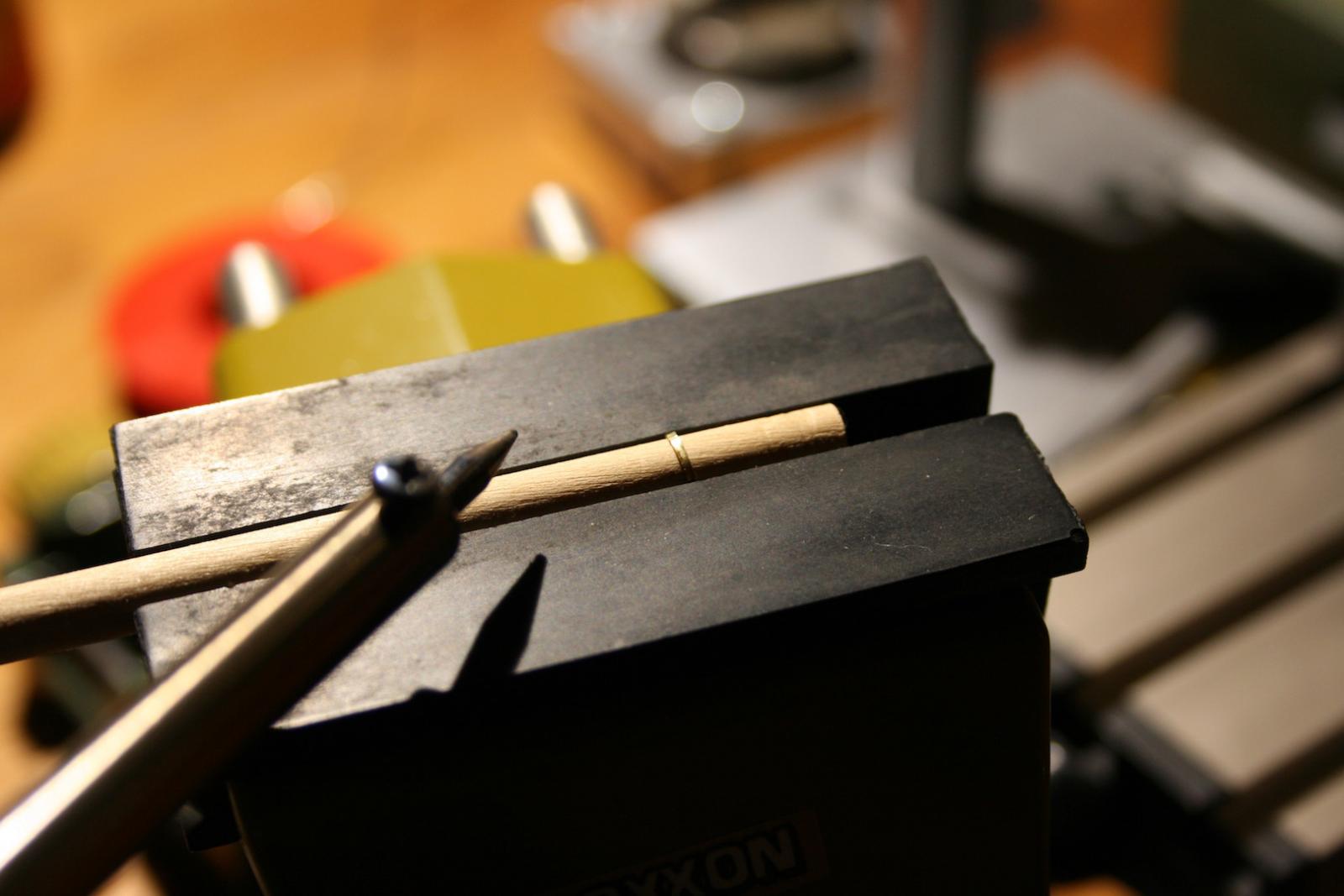
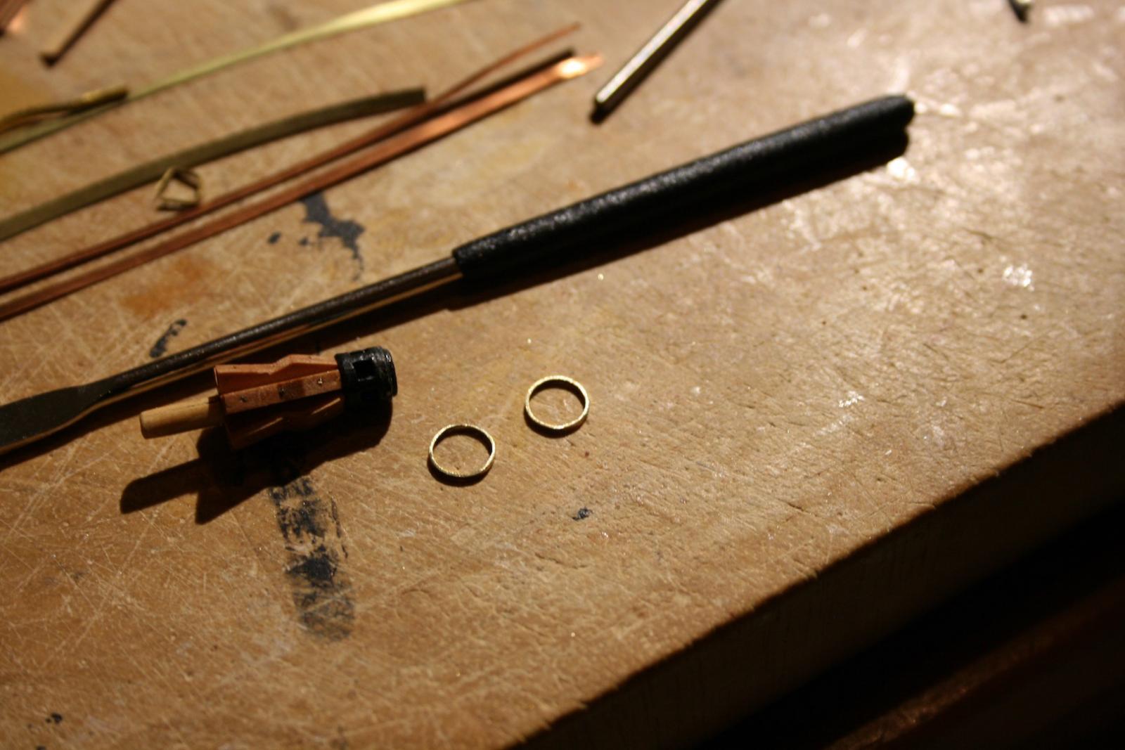
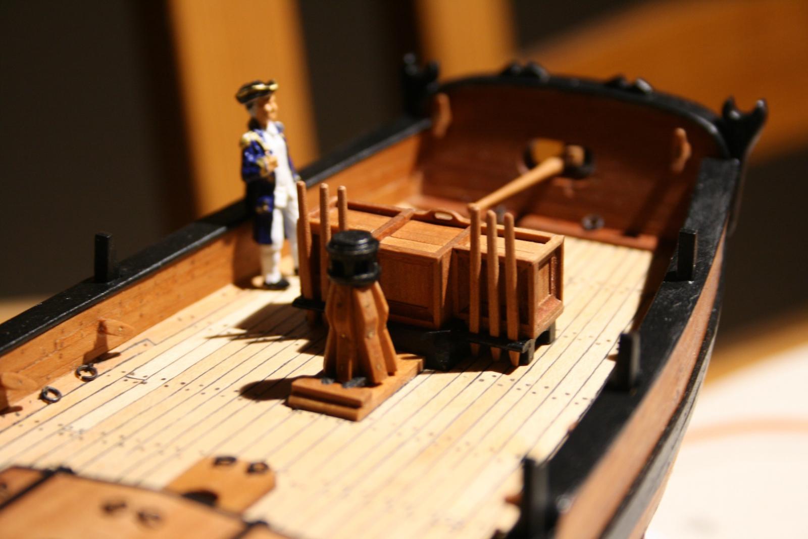
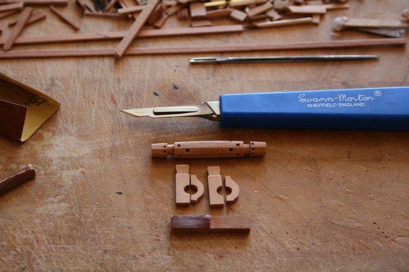
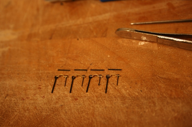
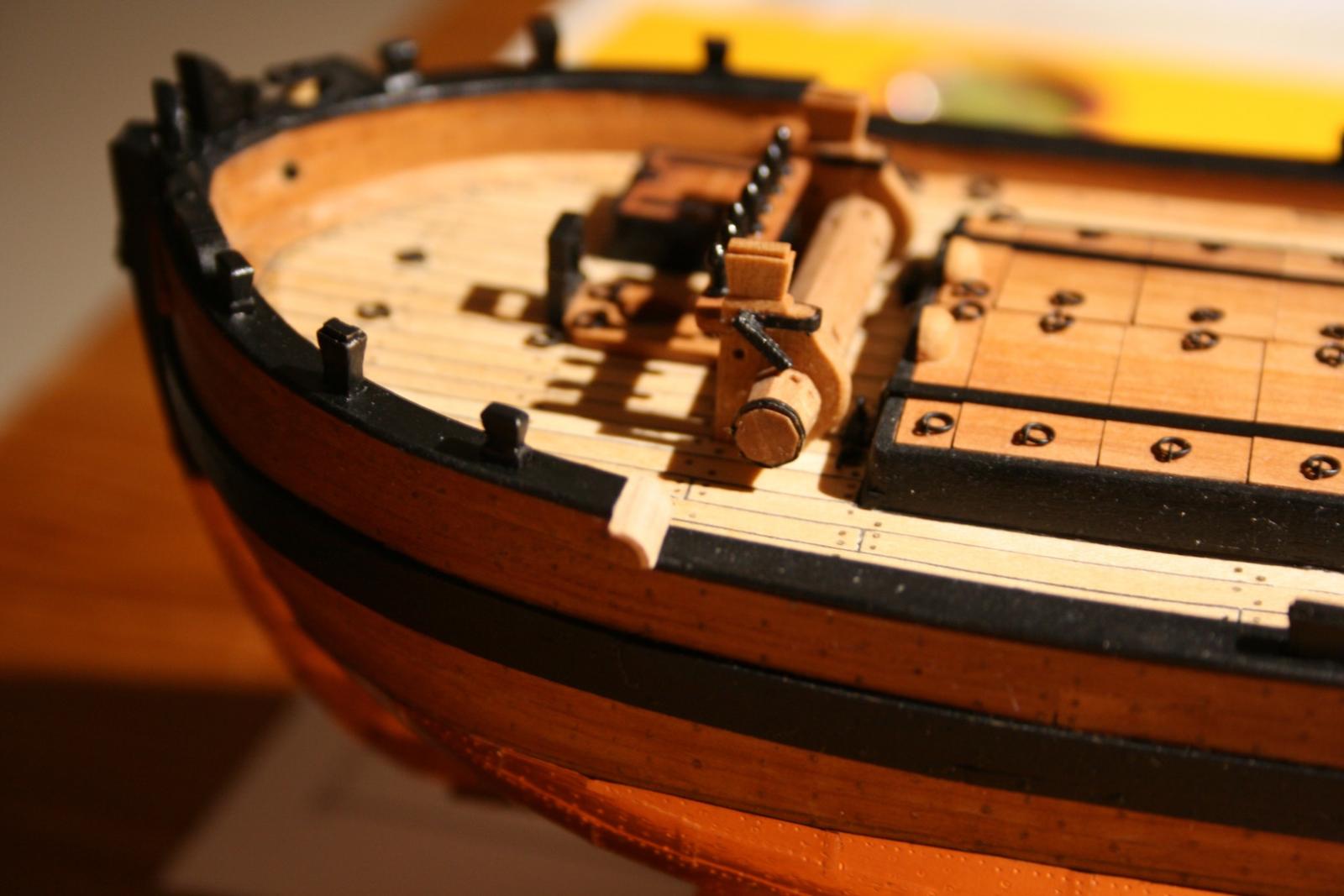
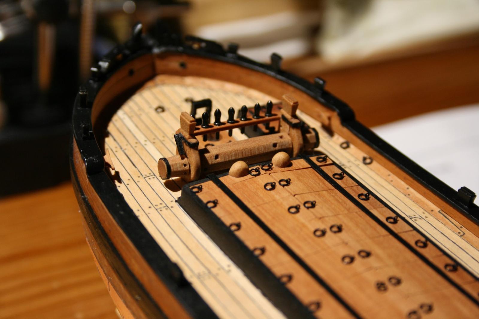
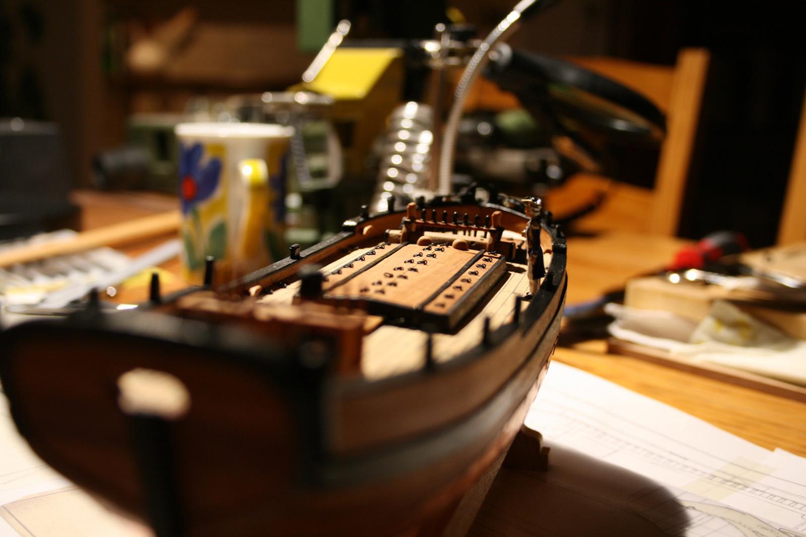
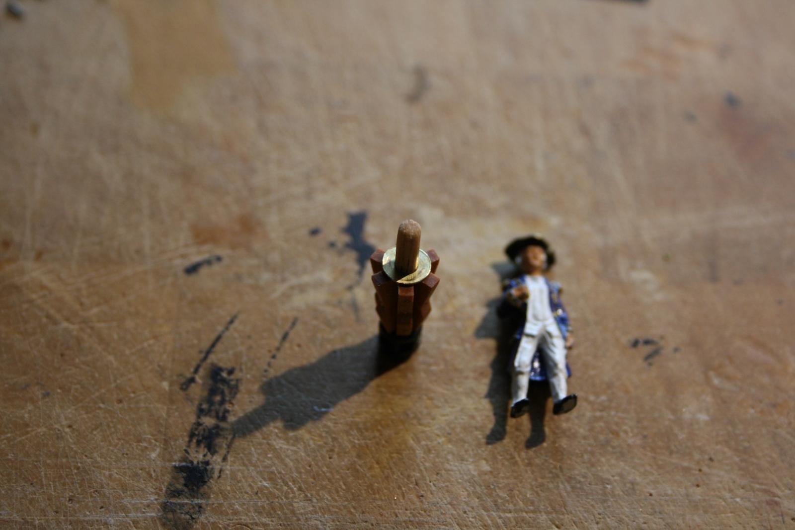
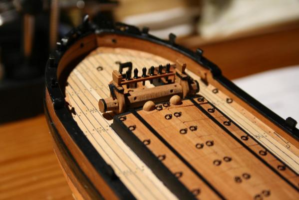
Hello all together out there, Thank you very much for your likes on my post. Today I've finished the my work on the capstan. Daniel