tkay11
-
Posts
1,829 -
Joined
-
Last visited
Content Type
Profiles
Forums
Gallery
Events
Everything posted by tkay11
-
 Wonderful news, Jan! I hope the health problems are now over. It's great to see you back. As usual, there's no rush, so I look forward to seeing your progress when you have the time. Tony
 -
Thanks, Ulrich. I've often thought of making my own. Perhaps I'll get round to it this time! Tony
-
Ulrich, did you make your own block tumbler or did you buy one? If bought, what type is it and what is your experience? The reason I ask is that there was a long discussion some time back about block tumblers and the difficulties of tumbling small blocks. Thanks, Tony
-
George, it will be a delight to see you back at the forum with a new log. As you know, your work and your book have provided the central reference points for my own build, and as to the detailed explanations I can attribute much of that to your example as well! I am therefore really flattered that you have enjoyed my build thus far. I have refrained from entering my log for a while for two reasons. The first is simply that I have been learning about the various ways of rigging the ship by pursuing various books as well as asking detailed questions on the forum. The other is that I have at the same time been thinking hard about how I might approach a plank-on-frame build in the future. All this, by the way, whilst running around in various countries on work. At the moment I'm deep in rural Zambia, and won't be able to get back to any modelling till I return in just over a week. As to progress, I'm as far as having put on the shrouds and backstays, along with the mast tackle (or Burton pendants as they are referred to in Petersson). You may have noticed my question in the rigging forum about that tackle since I reckoned that Petersson had simplified it). When I get back, I'll probably post my progress up to that point although I'll be pretty busy until the end of November. I have spent quite some time working at making blocks of various types at the correct scale, and making sure I could make the rope correctly for the various sizes. Part of that was experimenting with dyes, and I have now settled on using walnut powder dye as used by cabinet makers in various dilutions (as recommended by Frolich in his Art of Shp Modelling). All this I find quite fascinating. It has been repeated many times on this forum that every single step is not only a lesson in history and skill in its own right, but that the piece in focus is also a model in its own right and that there are many ways of achieving a particular result. As a result I have no timetable to finish the build, but am very content just to plug along with each step and learn as much about it as I can. Of course I have made several mistakes along the way and have had to rebuild various parts many times, but I just put that down to the learning process and am always delighted that I can see some kind of progress -- though of course nothing to match the superb skills of the others from whom I learn so much. I remember that you said you spent 7 years on your own Sherbourne, so it is quite possible I will spend that amount of time as well. It'll be interesting to see. You'll be interested to know that I have pretty much decided to put sails on the ship in the same manner as you did -- so this definitely extended my learning process as well as the planning for the various bits of sail rigging. Thanks again, and apologies if I can't get on the internet for the next week to see if you reply! Tony
-
Mast tackles/Burton pendants in 1763 Cutter
tkay11 replied to tkay11's topic in Masting, rigging and sails
That's great, Henry! Just what I needed. Thank you very much. I presume 'served over' just means 'served'. Tony- 8 replies
-
- 2
-

-
- mast tackle
- burton pendant
- (and 2 more)
-
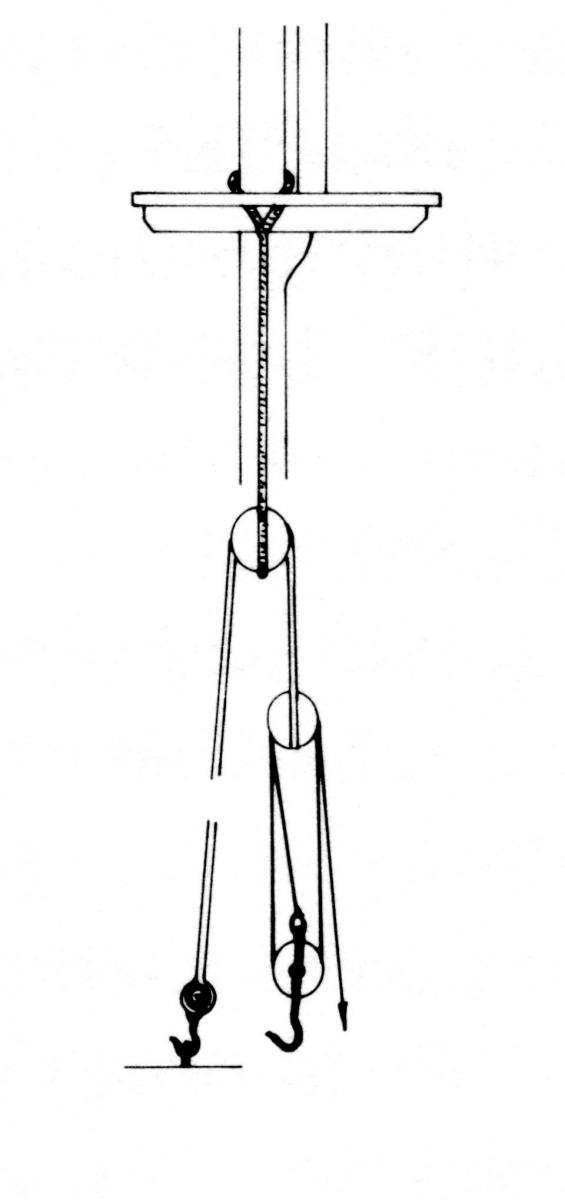
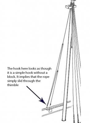
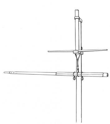
As usual, once I arrive at the point of making a particular part, I find the details confusing. This time it's about the mast tackles. The Sherbourne kit that I have doesn't illustrate or mention mast tackles or Burton pendants. Similarly, the 1763 cutter model I photographed in the Royal Dockyard doesn't have any. On the other hand, one of the cutter models (1790) I photographed does show a similar tackle hooked to the base of the mast as follows: Furthermore, Petersson in his book 'Rigging Period Fore and Aft Craft' shows what he calls a Burton pendant and tackle as follows (though I have added text to point out the difficulty I have with his diagram): This made me think it might be a good thing to set up mast tackles. However, the moment I started looking at this, I thought that the diagram didn't make mechanical sense. It shows the runner going through what looks like a hook without a block -- which would mean it would have to run through a thimble. When I looked up Marquardt's book on Eighteenth Century Rigs & Rigging, he shows the following arrangement: This is very similar to that shown by zu Mondfeld and is clearly more sound (to my mind) in terms of mechanics. Marquardt also supplies the following information about cutter rigging (following Steel) -- the last two paragraphs of which I am at a loss to understand: "The mast tackle pendants were wormed, parcelled and served over their whole length. Each was doubled, and the bight was seized to create an eye which fitted over the masthead. The ends were then spliced together, and a single block was seized in the lower bight. The ends of all splices were tapered, marled down and served over with spun-yarn. The tackle runners had a hook and thimble spliced into one end and were served over. They rove through the pendant blocks and were spliced round the strops of long tackle blocks. The tackle fall was bend to a becket at the lower end of a long stropped single block, with the ends seized. The long strops, with hooks and thimbles spliced in, were hooked to eyebolts in the sides." Here, I don't understand the terms 'served over' and 'long tackle blocks'. I also don't understand which 'long stropped single block' is being referred to as having the becket for the tackle fall. As a result I don't really know whether it's right to put mast tackles on, and, if I do, whether to try to mimic Petersson's diagram, or whether to go for the kind of picture Marquardt shows. Any advice, comment or other will be, as usual, very welcome! Tony

- 8 replies
-
- 3
-
-
- mast tackle
- burton pendant
- (and 2 more)
-
Help with Proxxon MF70
tkay11 replied to Bluto 1790's topic in Modeling tools and Workshop Equipment
Sorry, hadn't realised it was the base itself. Try Proxxon help. Tony -
Help with Proxxon MF70
tkay11 replied to Bluto 1790's topic in Modeling tools and Workshop Equipment
Those three adjusters are just screws that press on to a plate that holds the travelling table. I attach the instructions from the identical table that is sold separately. They are designed primarily to hold the table in the x-y axes. So if you loosen all the hexagonal surrounding nuts first, then, with the supplied allen key, loosen the left hand one and the right hand one, you'll find that there is considerable rotational play in those x-y axes. The diagram is: Although it's not supposed to adjust the play around the z axis, in fact you'll find that with the appropriate tightening of all three screws the play on the z axis will be minimised. This is simply because the plate is being pressed down on the table. However, you have to set that against stiffer movement in the x-y axes. Over-tightening will not only make the table very hard to move, but will also increase wear on the table itself. Of course, after loosening the screws, you'll have to make sure that when you tighten them again the table is indeed still perfectly aligned -- although in reality I don't think that's much of a problem. Once you've finished playing, don't forget to re-tighten the outer hexagonal nuts so that the screws don't change the positions you've decided on. If you want more help, a simple email via their website to Proxxon in Germany should do it. They are incredibly helpful over even the most minor details. Tony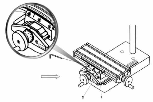
-
Tyes, slings and halliards on a 1763 revenue cutter
tkay11 replied to tkay11's topic in Masting, rigging and sails
Nice one, Henry! Thanks! As well as being very interesting! Tony- 4 replies
-
- 1
-
-
- cutter
- Sherbourne
- (and 3 more)
-
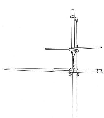
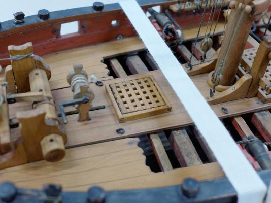
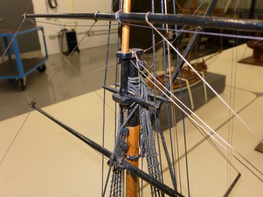
I'm still beavering away at working out the rigging for my Sherbourne cutter of 1763. For reasons given in my build log, I decided to go with the rigging plan shown by Petersson in his book on rigging period fore and aft craft -- rather than the plan shown with the kit. However, this has led me to a few puzzles, current of which is how the lower yard was held. Having prepared the shrouds, backstays and Burton pendants, I was looking at the plans for holding the lower yard. Petersson shows the following: This leaves me puzzled as to how the yard was lowered or raised if just a sling was used. The books I have don't give me a straight answer. Several, such as those by Marquardt, show halliards with blocks (as do the plans for the Sherbourne). Others show just a sling, as does zu Mondfeld: Models in the Royal Dockyard at Chatham show some with a halliard and blocks, whilst others show just a simple sling. Thus a model of a 1763 cutter in Chatham shows the lower yard with a halliard and blocks as follows: I'd be grateful if someone could explain to me whether tyes with blocks were used instead of slings (or vice versa), or whether a ship could be fitted with either (depending on circumstances), or whether both were used together. I have a feeling I'm missing out on understanding function here, so any guidance will, as always, be very welcome! Thanks Tony

- 4 replies
-
- 2
-
-
- cutter
- Sherbourne
- (and 3 more)
-
Don't worry, the pics are self-explanatory. In any case, the book you're getting covers the detail. Tony
-
In addition to the builds on this site, there are a couple of La Jacinthe builds on the French modelling site Marine et Modélisme d'Arsenal which you may want to look at (though the details of the builds are lacking): http://5500.forumactif.org/t1916-la-jacinthe-en-charpente?highlight=jacinthe http://5500.forumactif.org/t1490-la-jacinthe-de-snarlev-au-1-48eme?highlight=jacinthe Tony
-
I don't know if you have seen Frolich's Art of Ship Modelling, but in that he shows how he built La Jacinthe using exactly the plug kind of construction you're talking about. I'll send you by PM a pdf of the relevant pages if you like. There have also been a few builds on this forum of similar ships, but they were on MSW 1.0 and may no longer be available. There are also a few books on modelling that discuss this technique -- but I can't think at the moment where I saw the discussions. An interesting take on the method is in the build 'Istanbul Kayigi by Ilhan Gokcay - (Coastal trade vessel of Istanbul) 18th c. Scale:1/50' which you can see at http://modelshipworld.com/index.php/topic/506-istanbul-kayigi-by-ilhan-gokcay-coastal-trade-vessel-of-istanbul-18th-c-scale150/?hl=%2Bgokcay+%2Bistanbul. In that it looks as though he's going to build a straightforward plank on bulkhead model with complete filling between the bulkheads, but scroll through the pictures and you'll have a shock -- it's in fact to act as a plug. Tony
-
If you're in the UK, Warco make an excellent range. See http://www.warco.co.uk/search.php?orderby=position&orderway=desc&search_query=magnifier&submit_search= I bought the magnifier LED round lens in February last year. Their after-sales service and advice is wonderful, and I haven't found similar lamps cheaper in the uk. Tony
-
Which model engineering show are you going to? I haven't noticed any in the calendar at the Model Engineer website. Tony
- 188 replies
-
- 1
-
-
- Sherbourne
- Caldercraft
- (and 2 more)
-
Too what degree are shrouds and stays served
tkay11 replied to markjay's topic in Masting, rigging and sails
In my copy on Page 50 it seems to have been corrected. It reads "These shrouds are of 7" cable and their laniards are 3 1/2" line." It seems corrections are made on the hoof as people notice them. My copy arrived a month ago. Tony -
How about some TurboCAD help?
tkay11 replied to jwileyr4's topic in CAD and 3D Modelling/Drafting Plans with Software
If you click on the generic line tool you'll see a box with what looks like an inverted T. That allows you to select a line to which you'd like to draw the perpendicular, then the length of the perpendicular and finally the end point of the perpendicular. Tony -
It may be that you have to convert your pictures to jpg before they can be viewed on this site. Tony
- 17 replies
-
- 1
-
-
- abythistos
- cutter
- (and 2 more)
-
Dr. Mike's videos are up to 95 now. He's the one publishing them on YouTube. As before his full list of videos is at https://www.youtube.com/playlist?list=PL5wX2_PJGI8sxN_zzXNTWaZ9qi-U_9Zp7 Tony
-
Thanks, Mick. Useful info. I'd looked at a Peatol/Taig before and wondered how it would compare with the ARC models. I see it's set up for imperial units only, but suppose that's not much of a problem. Sorry for diverting the thread! Tony
-
Looks like a nice lathe. Which lathe is it? Bought in the UK? The reason I ask is that I'm looking for one myself. Tony
-
What a great sense of satisfaction and pride you must have! I've often wondered if at the end of a build there's also a sense of anti-climax, as though you can't quite believe it's all over. Looking forward to your next build Tony
- 63 replies
-
- 2
-
-
- amati
- lady nelson
- (and 2 more)