Srodbro
-
Posts
299 -
Joined
-
Last visited
1 Follower

Recent Profile Visitors
2,903 profile views


-
 Srodbro reacted to a post in a topic:
Gjøa 1872 by Harvey Golden - Roald Amundsen's Cutter built at Rosedahl, Norway
Srodbro reacted to a post in a topic:
Gjøa 1872 by Harvey Golden - Roald Amundsen's Cutter built at Rosedahl, Norway
-
Srodbro reacted to a post in a topic:
Kate Cory by Capt. Kelso (Quint) - Model Shipways - 3/16" scale - Whaling Brig
-
Srodbro reacted to a post in a topic:
Kate Cory by Capt. Kelso (Quint) - Model Shipways - 3/16" scale - Whaling Brig
-
Srodbro reacted to a post in a topic:
Ship paintings
-
Very nice work on the boats.
-
Srodbro reacted to a post in a topic:
Kate Cory by Capt. Kelso (Quint) - Model Shipways - 3/16" scale - Whaling Brig
-
Srodbro reacted to a post in a topic:
US Brig Niagara by Usgecko - Model Shipways - 1:64 Scale
-
Archi reacted to a post in a topic:
Was ship's painted in the UK back in 1600's ?
-
Srodbro reacted to a post in a topic:
Kate Cory by Capt. Kelso (Quint) - Model Shipways - 3/16" scale - Whaling Brig
-
It only reinforces the joint. Any farther in would obstruct the holes for belaying pins. I also anchored the fife rails to the deck with brass pins. . I used the same method on the channels and pinrails, as well.
-
Jolly Jo reacted to a post in a topic:
US Brig Niagara by Usgecko - Model Shipways - 1:64 Scale
-
Coyote_6 reacted to a post in a topic:
US Brig Niagara by Usgecko - Model Shipways - 1:64 Scale
-
I’ve followed your build with interest. Nice work. One suggestion: You might consider reinforcing the joinery on your fife rails as I did with a bit of brass wire. Later on when you are rigging, a bit too much tension on a line could cause the rails to come apart at a time in the build when repairing the fife rails would be extremely difficult ( as I discovered to my dismay on a previous build). Just a thought. Here is a pic of what I did on my Niagara fife rails.

-
phebe reacted to a post in a topic:
HMS Sophie by TBlack - kit-bashing Jack Aubrey's first command from the Vanguard Models HMS Speedy
-
Keith Black reacted to a post in a topic:
Using styrene for making structures on modern ships
-
JKC27 reacted to a post in a topic:
Using styrene for making structures on modern ships
-
shipman reacted to a post in a topic:
Using styrene for making structures on modern ships
-
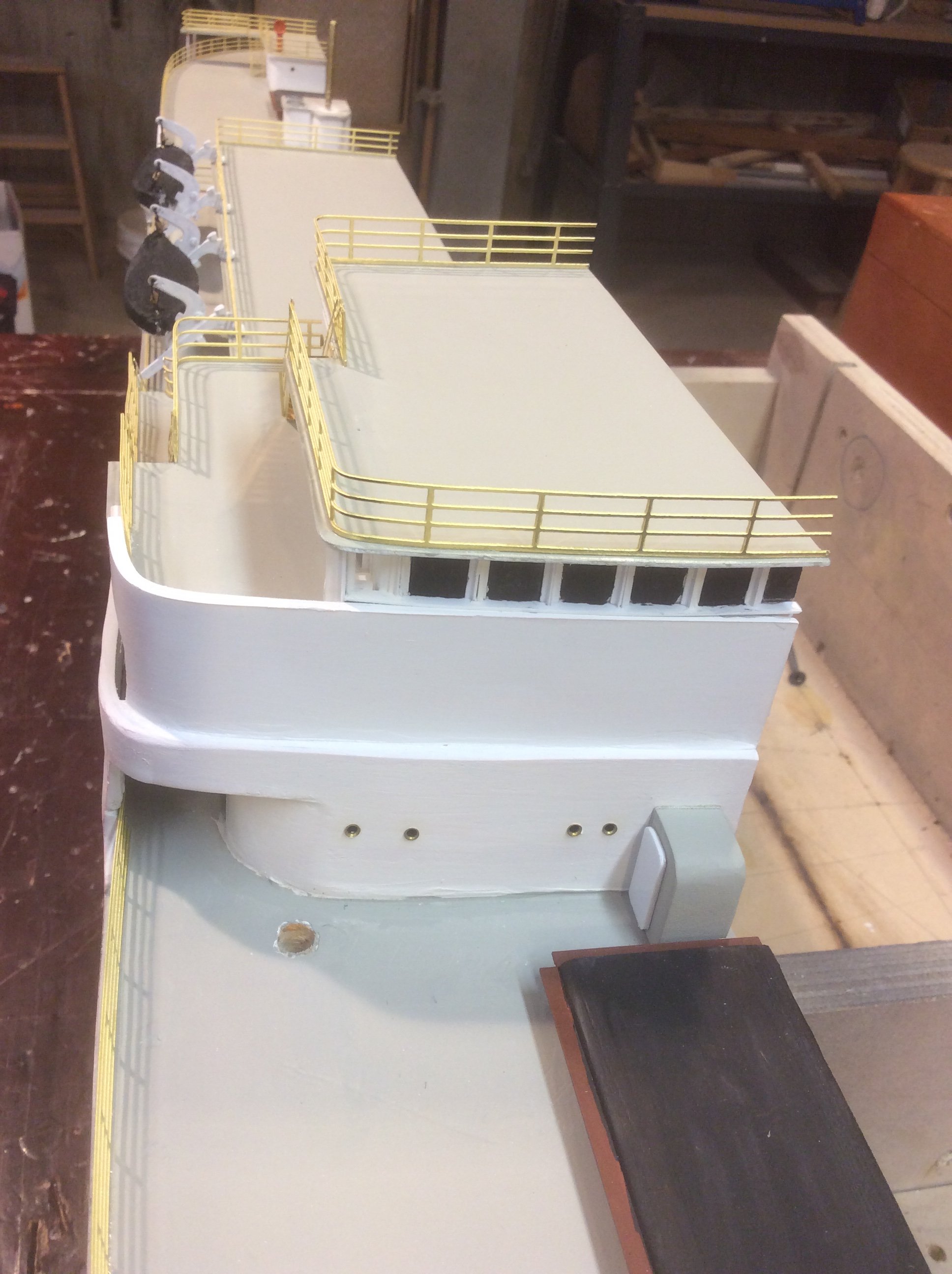
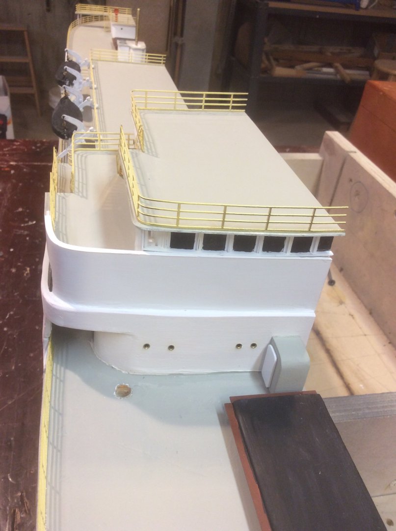
Much depends, I suppose, on the scale to which you are working. On my Fra Berlanga ( approx 1:100), I modeled the structure of wood and styrene, applied clear plastic painted on the reverse with black, then used styrene “ angle iron” strips to detail framing around each window. If I was working at a smaller scale, I might cut a window hole as well as I could, then trim around the individual opening, maybe with card strips, or ( what I have become enamored with lately) aluminum tape ( as used by insulation and sheet metal workers) painted, cut to size with scissors and applied around the opening.
-
Srodbro reacted to a post in a topic:
Gjøa 1872 by Harvey Golden - Roald Amundsen's Cutter built at Rosedahl, Norway
-
Srodbro reacted to a post in a topic:
Gjøa 1872 by Harvey Golden - Roald Amundsen's Cutter built at Rosedahl, Norway
-
Glen McGuire reacted to a post in a topic:
Gjøa 1872 by Harvey Golden - Roald Amundsen's Cutter built at Rosedahl, Norway
-
Keith Black reacted to a post in a topic:
Gjøa 1872 by Harvey Golden - Roald Amundsen's Cutter built at Rosedahl, Norway
-
Harvey Golden reacted to a post in a topic:
Gjøa 1872 by Harvey Golden - Roald Amundsen's Cutter built at Rosedahl, Norway
-
Here’s a quote from Brown’s book: ”As the days grew darker and colder, the men tried to prepare themselves psychologically for the dreaded monotony of the long winter they faced living in the deserted, frozen expanse under a dome of perpetual dark. The daily routine, as far as anyone could predict, would consist of magnetic observations, hunting, taking care of the dogs and feeding themselves, with only a few extended excursions to pass the many months. The members of the small band had already grown tired of each others’ company, and with little to occupy them once winter set in, the lack of new company proved to be the greatest challenge.” Add to that the discovery of blond haired, blue-eyed Inuit several years later … Yeah … plenty there to dramatize!
-
Srodbro reacted to a post in a topic:
Roter Löwe 1597 by Ondras71
-
See Harvey’s post #1 ( there is an English version of Northwest Passage) and the book The Last Viking by Stephen Brown.
-
Being grandson to a blacksmith and great-nephew to a wheelwright I was attracted to this kit as a break from model shipbuilding, and I have just finished building it. I found your build log very helpful especially for the reach-fifth wheel assembly … I agree, the instructions could have been better in this regard. Regarding the question of when to paint the Britannia fittings: There seems to be no avoiding several attempts, whether painted prior to assembly or after. Seems every modeling session included painting and touch-up. Regarding the wheel spoke length: You are right, they are exactly the right length. In fact, I found that after cleaning the char from the spokes and rims, the spokes were too short. I solved this by wrapping the interior groove of the hubs with several turns of tape to effectively make the hub diameter larger. The kit, I thought, was deficient in a couple of ways. First, there is no detailing of any breaking mechanism. Second, and more frustratingly, there is no means for attaching the wagon to a horse, even after purchasing the single horse harness-hitch kit. Conceivably, the mysterious “axel couplings” might have been intended to facilitate the attachment of the poles running from the front axel along the sides of a horse for steering, but there is no hint in the wagon kit ( nor in the harness-hitch kit) that this is the case. But, I couldn’t have been too disappointed with the kit since I have recently purchased the beer wagon and two-horse hitch kits. Again, it was a big help following your log.
-
Good to see you are back.
-
Micro-Mark Desktop Dust Collection System
Srodbro replied to eurekapaul's topic in Modeling tools and Workshop Equipment
I spent some years designing dust and fume collection systems for laboratories and research facilities. Most devices like this are of little value; it’s the nature of the beast. Try this experiment: Get your vacuum cleaner hose, and hold your hand a 1/4” from the nozzle. Feel the air movement? Ok, now move your hand 1” from the nozzle: you probably can’t feel air moving, or just barely. 2” away you feel nothing. Now, connect your vacuum hose to the discharge of the vacuum ( if you can). You can hold your hand several feet from the discharge and still feel the air movement. Why the difference? Air best flows to where it is pushed, not pulled. The suction of the hose is relying on barometric pressure to push the air into it ( essentially, the vacuum hose creates a “ hole” in the surrounding area near the nozzle that the air “falls” into). On the discharge end, the energy from the vacuum cleaner motor has been imparted to the air and will move with more force. To better control the particles in the air, get a small fan to blow across your work surface away from you. -
Glad to see you are back. Yeah, looking forward to doing ratlines is about the least motivating step in a build, but once they are done, you are so much closer to doing running rigging, which I think is motivating. Great looking build.
-
Any words of wisdom regarding the veracity of other woods they sell, like Cherry or walnut?
-
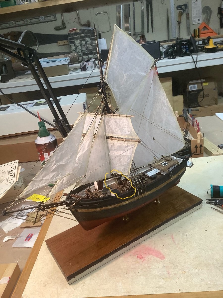
I recently completed my version of Gjoa, which I did with sails. I had the same question about that item, and as near as I could tell it is where the sheet of the fore staysail attaches to the rail traversing the deck forward of the mast. I think the term comes from the idea that this line would “ slap” from port to starboard ( or vice-versa) while tacking. Here is a not so clear pic of my model with the subject circled in yellow. At least, that is how I interpreted it. Though, keep in mind my Norwegian is limited to “ Aquavit” and “Skol”!

-
I am always blow-away by the micro-soldering skills on these forums. Wonderful work!
-
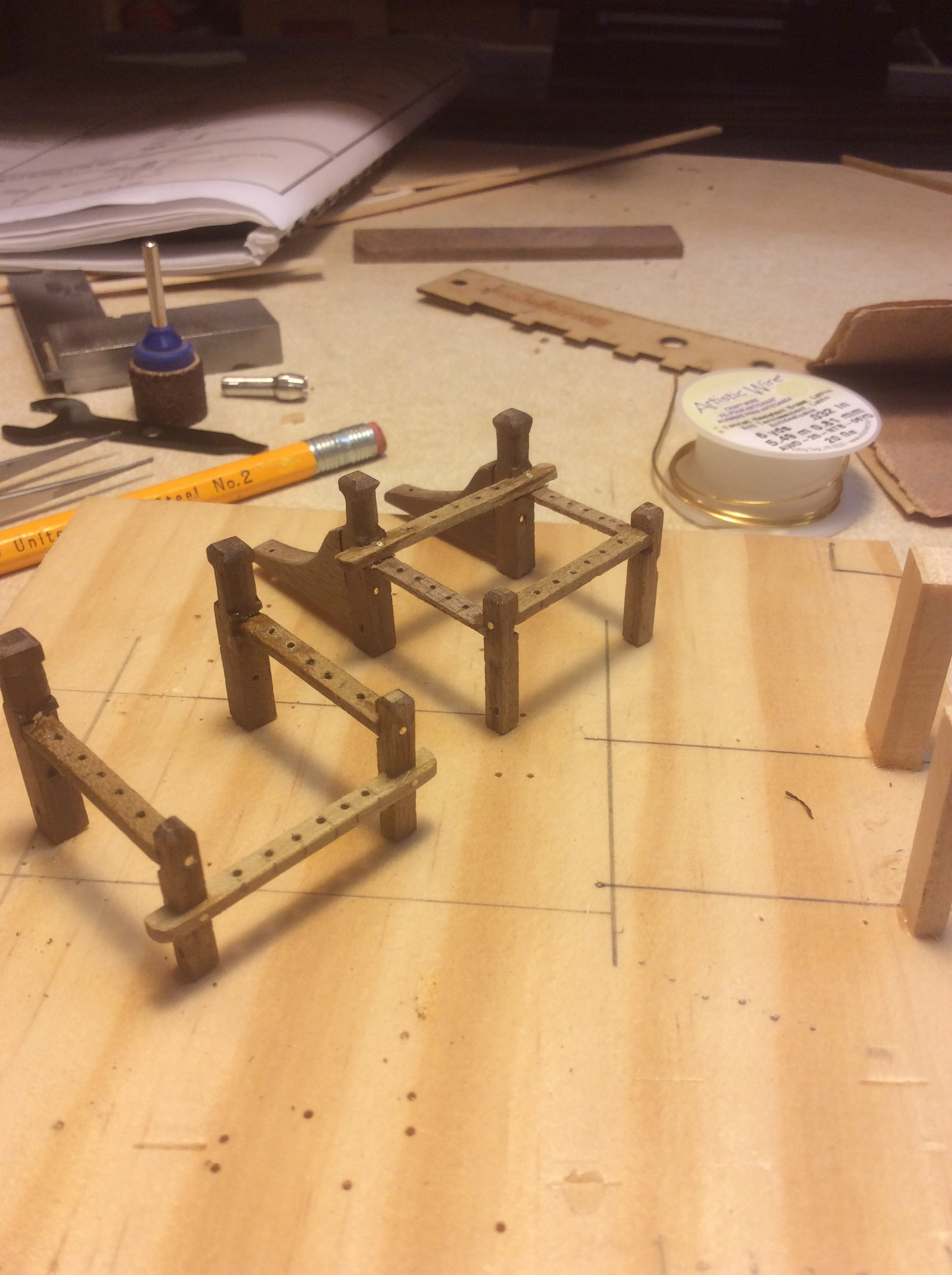
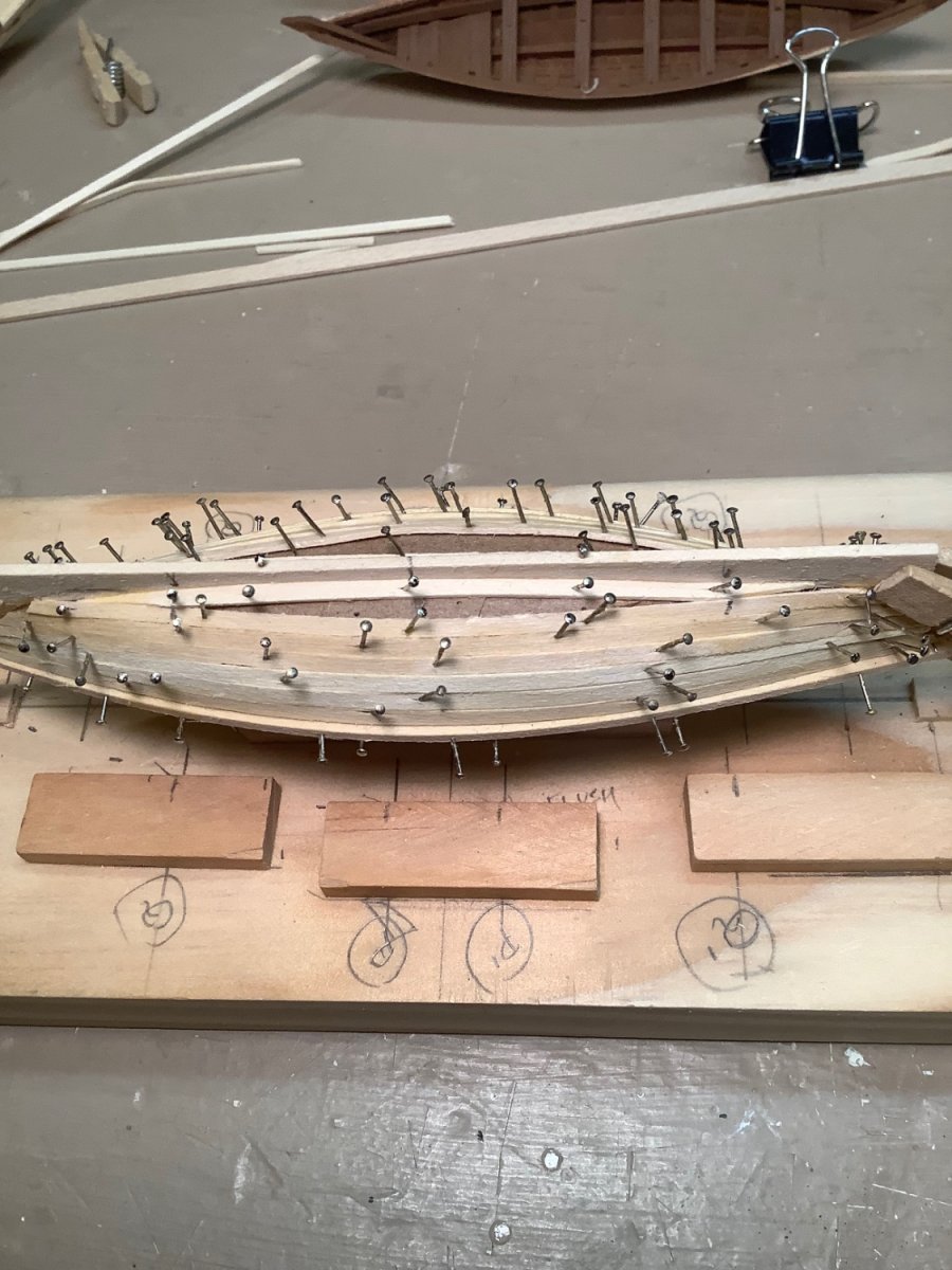
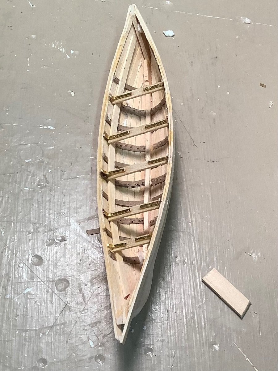
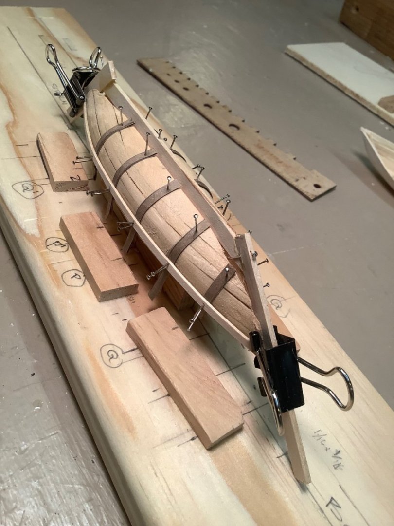
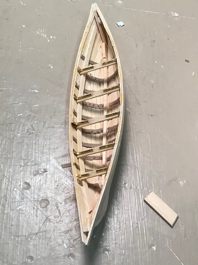
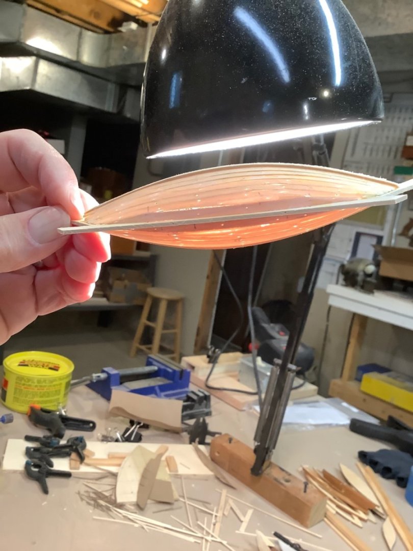
Your boats are progressing nicely. I am concurrently building Morgan and Kate Cory whalers, and decided to first build all the boats for both (like 12 of them). There are some really good examples of whaleboats built by other modelers on these forums, and I cannot dare to compare in the finished quality. I have never had success at grinding/ sanding the interior of these small boats ( uneven, poke-thru’s). So, I used a different methodology. Using the lines provided on the kit drawings, I built a mold upon which I assembled keel and paper ribs, then planking. Filling and sanding gave me a thin hull. Now, honestly I used the center “ scrap” portions of the laser cut boat parts for my mold pattern, so dimensionally I am not super accurate. Nonetheless, I found it sufficed for my purposes. Now, my craftsmanship is far below that of others, but with a bit more patience and skill, and attention to detail ( like more attention to uniformity and number of ribs, etc,) I think this methodology used by the right hands, could be a viable building alternative. Just a suggestion. Love following your progress.

-
Missing your posts. Great work.