

tlevine
-
Posts
2,020 -
Joined
-
Last visited
Reputation Activity
-

 tlevine got a reaction from archjofo in NRG Rigging Project by tlevine - FINISHED
The lower yard is specified on the plans as 41.5 feet long, with a centerline diameter of 9.2”. Just like the mast, the yard is divided into quarters. There are four quarters on either side of the centerline. The two center quarters are octagonal and the yard tapers from 9.2” to 7.8” at the end of the second quarter. Because this is a desktop model, I did not want the yard to extend beyond the side of the hull and made only the middle twenty-five feet.
To make the yard, I started just like the mast, marking the dimensions on all four sides of the dowel. Because this is such a short piece of wood, a template was not necessary. The center octagonal section was made first. Then I wrapped tape around the center quarters to protect them and tapered the outer part of the yards. Finally, I rounded the tapered portions with sandpaper. The drawing illustrates the dimensions.
A pin was placed in the center point of the yard to secure it to the mast. The yard sits at the level of the futtock stave so I drilled a corresponding hole in the mast. You can see the mast hole location in the picture in the previous post, just above the uppermost woolding.
Nine blocks were installed on the yard. The jeer block is part of a pulley system to raise the yard. Its configuration changed several times in the eighteenth century and varied with different sized ships. This configuration is appropriate for a ship smaller than 28 guns in the last quarter of the 18th century. Quarter blocks carry the topsail sheet falls. Clew lines run from the corner of the lower sails (the clews) through the clew blocks. The buntlines raise the foot of the sail for furling and run through the bunt blocks.
The quarter blocks were installed first. The kit will include 5 mm blocks; mine were slightly larger to be the correct length of 5.2 mm. These blocks are stropped with served line. This is my technique. Serve a piece of line that you think will be the right length; on my model this was 1.6”. This is running rigging so the serving thread is natural color. I used Gutterman sewing thread. Leave a long tail of serving thread on either end.
The first step was to make a loop at one end. Untwist a short segment of rope next to the end of the serving on one side and cut the untwisted threads at a 45-degree angle to decrease the bulk. Form a loop, with the untwisted threads laying alongside the served part of the rope. With the tail of serving thread, wrap the untwisted threads and previously served line. In actual practice, the untwisted line would be laced into unserved rope and then the service would continue along the loop, terminating at the throat of the loop. Temporarily seize the block and measure how long the strop should be by wrapping it around the yard. The loop ends do not meet; a seizing will run between the loops to secure it to the yard. Make a kink in the rope to mark the spot. Remove the block and make the second loop the same way. Measure the length of the finished strop so you know how long to make the strop for the other side.
Reinsert the block and secure it with a throat seizing. The seizing is located on the fore side of the mast and the block hangs below the mast. This picture incorrectly shows the legs the same length. Finally, the strop was wrapped around the yard and the two loops were seized together.
-
 tlevine got a reaction from CiscoH in NRG Rigging Project by tlevine - FINISHED
The lower yard is specified on the plans as 41.5 feet long, with a centerline diameter of 9.2”. Just like the mast, the yard is divided into quarters. There are four quarters on either side of the centerline. The two center quarters are octagonal and the yard tapers from 9.2” to 7.8” at the end of the second quarter. Because this is a desktop model, I did not want the yard to extend beyond the side of the hull and made only the middle twenty-five feet.
To make the yard, I started just like the mast, marking the dimensions on all four sides of the dowel. Because this is such a short piece of wood, a template was not necessary. The center octagonal section was made first. Then I wrapped tape around the center quarters to protect them and tapered the outer part of the yards. Finally, I rounded the tapered portions with sandpaper. The drawing illustrates the dimensions.
A pin was placed in the center point of the yard to secure it to the mast. The yard sits at the level of the futtock stave so I drilled a corresponding hole in the mast. You can see the mast hole location in the picture in the previous post, just above the uppermost woolding.
Nine blocks were installed on the yard. The jeer block is part of a pulley system to raise the yard. Its configuration changed several times in the eighteenth century and varied with different sized ships. This configuration is appropriate for a ship smaller than 28 guns in the last quarter of the 18th century. Quarter blocks carry the topsail sheet falls. Clew lines run from the corner of the lower sails (the clews) through the clew blocks. The buntlines raise the foot of the sail for furling and run through the bunt blocks.
The quarter blocks were installed first. The kit will include 5 mm blocks; mine were slightly larger to be the correct length of 5.2 mm. These blocks are stropped with served line. This is my technique. Serve a piece of line that you think will be the right length; on my model this was 1.6”. This is running rigging so the serving thread is natural color. I used Gutterman sewing thread. Leave a long tail of serving thread on either end.
The first step was to make a loop at one end. Untwist a short segment of rope next to the end of the serving on one side and cut the untwisted threads at a 45-degree angle to decrease the bulk. Form a loop, with the untwisted threads laying alongside the served part of the rope. With the tail of serving thread, wrap the untwisted threads and previously served line. In actual practice, the untwisted line would be laced into unserved rope and then the service would continue along the loop, terminating at the throat of the loop. Temporarily seize the block and measure how long the strop should be by wrapping it around the yard. The loop ends do not meet; a seizing will run between the loops to secure it to the yard. Make a kink in the rope to mark the spot. Remove the block and make the second loop the same way. Measure the length of the finished strop so you know how long to make the strop for the other side.
Reinsert the block and secure it with a throat seizing. The seizing is located on the fore side of the mast and the block hangs below the mast. This picture incorrectly shows the legs the same length. Finally, the strop was wrapped around the yard and the two loops were seized together.
-
.jpg.d84ec4dad1d7791e855dca06210ab6f3.thumb.jpg.f45209242e851d4409eca1a09293165b.jpg) tlevine got a reaction from hollowneck in NRG Rigging Project by tlevine - FINISHED
tlevine got a reaction from hollowneck in NRG Rigging Project by tlevine - FINISHED
The futtock shrouds are attached to the futtock stave below and the futtock plate above. An eye with a thimble is spliced into the upper end of the futtock shroud. A double hook connects the shroud and the futtock plate.
To make the stropped thimble, I took some line and unfurl the end. Using a blunt needle, I made an opening in the line approximately the circumference of the thimble away from where the unfurling stopped and fed the unfurled end through the opening. Once the line has been passed through the opening, the opening will naturally retwist itself. A piece of brass tube (the thimble) was inserted into the eye and the splice was glued. The thimble was blackened after it was stropped because handling would have caused the patina to rub off.
The brass tube is slightly wider than the diameter of the rope. To keep the thimble from falling out of the splice, I placed it on an anvil and tapped each open end with a center punch. This added a slight lip to the thimble. The double S-hooks are 1/8” long and were made from 24 g wire, using round-nose pliers. The picture shows them attached to the futtock plates.
The futtock shroud was attached to the futtock stave by wrapping around the stave and securing it to the lower shroud with two round seizings. In the drawing, the futtock shroud is shown in red and the lower shroud in blue. After they were installed four rows of ratlines were added.
-
 tlevine got a reaction from Mr Whippy in NRG Rigging Project by tlevine - FINISHED
The lower yard is specified on the plans as 41.5 feet long, with a centerline diameter of 9.2”. Just like the mast, the yard is divided into quarters. There are four quarters on either side of the centerline. The two center quarters are octagonal and the yard tapers from 9.2” to 7.8” at the end of the second quarter. Because this is a desktop model, I did not want the yard to extend beyond the side of the hull and made only the middle twenty-five feet.
To make the yard, I started just like the mast, marking the dimensions on all four sides of the dowel. Because this is such a short piece of wood, a template was not necessary. The center octagonal section was made first. Then I wrapped tape around the center quarters to protect them and tapered the outer part of the yards. Finally, I rounded the tapered portions with sandpaper. The drawing illustrates the dimensions.
A pin was placed in the center point of the yard to secure it to the mast. The yard sits at the level of the futtock stave so I drilled a corresponding hole in the mast. You can see the mast hole location in the picture in the previous post, just above the uppermost woolding.
Nine blocks were installed on the yard. The jeer block is part of a pulley system to raise the yard. Its configuration changed several times in the eighteenth century and varied with different sized ships. This configuration is appropriate for a ship smaller than 28 guns in the last quarter of the 18th century. Quarter blocks carry the topsail sheet falls. Clew lines run from the corner of the lower sails (the clews) through the clew blocks. The buntlines raise the foot of the sail for furling and run through the bunt blocks.
The quarter blocks were installed first. The kit will include 5 mm blocks; mine were slightly larger to be the correct length of 5.2 mm. These blocks are stropped with served line. This is my technique. Serve a piece of line that you think will be the right length; on my model this was 1.6”. This is running rigging so the serving thread is natural color. I used Gutterman sewing thread. Leave a long tail of serving thread on either end.
The first step was to make a loop at one end. Untwist a short segment of rope next to the end of the serving on one side and cut the untwisted threads at a 45-degree angle to decrease the bulk. Form a loop, with the untwisted threads laying alongside the served part of the rope. With the tail of serving thread, wrap the untwisted threads and previously served line. In actual practice, the untwisted line would be laced into unserved rope and then the service would continue along the loop, terminating at the throat of the loop. Temporarily seize the block and measure how long the strop should be by wrapping it around the yard. The loop ends do not meet; a seizing will run between the loops to secure it to the yard. Make a kink in the rope to mark the spot. Remove the block and make the second loop the same way. Measure the length of the finished strop so you know how long to make the strop for the other side.
Reinsert the block and secure it with a throat seizing. The seizing is located on the fore side of the mast and the block hangs below the mast. This picture incorrectly shows the legs the same length. Finally, the strop was wrapped around the yard and the two loops were seized together.
-
tlevine got a reaction from hollowneck in NRG Rigging Project by tlevine - FINISHED
The lower yard is specified on the plans as 41.5 feet long, with a centerline diameter of 9.2”. Just like the mast, the yard is divided into quarters. There are four quarters on either side of the centerline. The two center quarters are octagonal and the yard tapers from 9.2” to 7.8” at the end of the second quarter. Because this is a desktop model, I did not want the yard to extend beyond the side of the hull and made only the middle twenty-five feet.
To make the yard, I started just like the mast, marking the dimensions on all four sides of the dowel. Because this is such a short piece of wood, a template was not necessary. The center octagonal section was made first. Then I wrapped tape around the center quarters to protect them and tapered the outer part of the yards. Finally, I rounded the tapered portions with sandpaper. The drawing illustrates the dimensions.
A pin was placed in the center point of the yard to secure it to the mast. The yard sits at the level of the futtock stave so I drilled a corresponding hole in the mast. You can see the mast hole location in the picture in the previous post, just above the uppermost woolding.
Nine blocks were installed on the yard. The jeer block is part of a pulley system to raise the yard. Its configuration changed several times in the eighteenth century and varied with different sized ships. This configuration is appropriate for a ship smaller than 28 guns in the last quarter of the 18th century. Quarter blocks carry the topsail sheet falls. Clew lines run from the corner of the lower sails (the clews) through the clew blocks. The buntlines raise the foot of the sail for furling and run through the bunt blocks.
The quarter blocks were installed first. The kit will include 5 mm blocks; mine were slightly larger to be the correct length of 5.2 mm. These blocks are stropped with served line. This is my technique. Serve a piece of line that you think will be the right length; on my model this was 1.6”. This is running rigging so the serving thread is natural color. I used Gutterman sewing thread. Leave a long tail of serving thread on either end.
The first step was to make a loop at one end. Untwist a short segment of rope next to the end of the serving on one side and cut the untwisted threads at a 45-degree angle to decrease the bulk. Form a loop, with the untwisted threads laying alongside the served part of the rope. With the tail of serving thread, wrap the untwisted threads and previously served line. In actual practice, the untwisted line would be laced into unserved rope and then the service would continue along the loop, terminating at the throat of the loop. Temporarily seize the block and measure how long the strop should be by wrapping it around the yard. The loop ends do not meet; a seizing will run between the loops to secure it to the yard. Make a kink in the rope to mark the spot. Remove the block and make the second loop the same way. Measure the length of the finished strop so you know how long to make the strop for the other side.
Reinsert the block and secure it with a throat seizing. The seizing is located on the fore side of the mast and the block hangs below the mast. This picture incorrectly shows the legs the same length. Finally, the strop was wrapped around the yard and the two loops were seized together.
-
 tlevine got a reaction from thibaultron in NRG Rigging Project by tlevine - FINISHED
The lower yard is specified on the plans as 41.5 feet long, with a centerline diameter of 9.2”. Just like the mast, the yard is divided into quarters. There are four quarters on either side of the centerline. The two center quarters are octagonal and the yard tapers from 9.2” to 7.8” at the end of the second quarter. Because this is a desktop model, I did not want the yard to extend beyond the side of the hull and made only the middle twenty-five feet.
To make the yard, I started just like the mast, marking the dimensions on all four sides of the dowel. Because this is such a short piece of wood, a template was not necessary. The center octagonal section was made first. Then I wrapped tape around the center quarters to protect them and tapered the outer part of the yards. Finally, I rounded the tapered portions with sandpaper. The drawing illustrates the dimensions.
A pin was placed in the center point of the yard to secure it to the mast. The yard sits at the level of the futtock stave so I drilled a corresponding hole in the mast. You can see the mast hole location in the picture in the previous post, just above the uppermost woolding.
Nine blocks were installed on the yard. The jeer block is part of a pulley system to raise the yard. Its configuration changed several times in the eighteenth century and varied with different sized ships. This configuration is appropriate for a ship smaller than 28 guns in the last quarter of the 18th century. Quarter blocks carry the topsail sheet falls. Clew lines run from the corner of the lower sails (the clews) through the clew blocks. The buntlines raise the foot of the sail for furling and run through the bunt blocks.
The quarter blocks were installed first. The kit will include 5 mm blocks; mine were slightly larger to be the correct length of 5.2 mm. These blocks are stropped with served line. This is my technique. Serve a piece of line that you think will be the right length; on my model this was 1.6”. This is running rigging so the serving thread is natural color. I used Gutterman sewing thread. Leave a long tail of serving thread on either end.
The first step was to make a loop at one end. Untwist a short segment of rope next to the end of the serving on one side and cut the untwisted threads at a 45-degree angle to decrease the bulk. Form a loop, with the untwisted threads laying alongside the served part of the rope. With the tail of serving thread, wrap the untwisted threads and previously served line. In actual practice, the untwisted line would be laced into unserved rope and then the service would continue along the loop, terminating at the throat of the loop. Temporarily seize the block and measure how long the strop should be by wrapping it around the yard. The loop ends do not meet; a seizing will run between the loops to secure it to the yard. Make a kink in the rope to mark the spot. Remove the block and make the second loop the same way. Measure the length of the finished strop so you know how long to make the strop for the other side.
Reinsert the block and secure it with a throat seizing. The seizing is located on the fore side of the mast and the block hangs below the mast. This picture incorrectly shows the legs the same length. Finally, the strop was wrapped around the yard and the two loops were seized together.
-
 tlevine reacted to Chuck in Sloop Speedwell 1752 by Chuck - Ketch Rigged Sloop - POF - prototype build
The hawse holes can be complex but if you spend a lot of time preparing and measuring it will go smoothly. Before I begin describing my process here is a look at the contemporary model. You can see many close up details here.
I started by preparing some new templates. They are very much like the other templates but I wanted to add some other reference lines to help me more with aligning the hawse holes. So these are the ones you want to use when you get this stage.
You will note a few things in that photo. First you will see the dashed vertical lines I added that extend up to the cap rail. These will allow you to mark the locations of the hawse holes on top of the cap rail. To do this I cut some painters tape to the width of the hawse holes and placed it on the cap rail using the template as a guide. The tape runs parallel to the keel across the cap rail.
You will also notice how I cut the hawse holes from the template so I could use it as a stencil after taping it to the hull. I also cut an opening to mark the location of the hawse hoods or naval hoods. These are the plates that sit over the planking. The template sits on top of the wales as before. The forward edge sits against the stem.
I of course cut away the molding strip on the hull before I taped the template in position. I dont want to forget to mention that. Then I traced the hawse holes onto the hull.
On the inboard side of the hull, I prepared another template specifically for the hawse holes. Note the dashed lines again that extend to the cap rail. This template was lined up with the tape I placed across the cap rail. This will be the path I plan to drill through the hull for the hawse holes. This was a lot of measuring and planning to come up with these templates but it all worked out well. Just trace the hawse holes on the inboard side as well. Note how the template is sitting on the deck which establishes the correct height...I hope.
I didnt take any pictures right after drilling the hawse holes. I cant believe I forgot to do it. But let me explain the process. I drilled them out using progressively larger drill bits. I drilled from both sides. I drilled half way through from the front and then switched to inboard. I drilled half way through until the holes met in the middle and the first small hole was clear and through. Then I switched to a slightly larger drill bit and repeated the process. I increased them until the hawse holes were almost full size and then I switched to a round file to clean them up and enlarge them further.
THE ENTIRE time while drilling from the outboard side I used the blue tape on the top of the cap rail to guide the drill bit at the same angle. Following the keel. The hawse holes are almost level in height inboard and outboard with only a slight upward angle needed as you drill from the outboard side. A very slight angle. Not to worry if its not exact because when you dill from the inboard side to meet the outside hole it should all meet up decently.
I touched up the red paint inboard and used a soft pencil to darken the insides of the hawse holes black...to represent lead or tin I suppose.
Next up was to add the Hawse hoods or Naval hoods on the outboard side. These are made in two layers. They are laser cut and on the outermost end is a laser etched detail. This small etched detail wouldnt be difficult to carve with a sharp chisel. But I just assume etch it onto the ends. This means you must clean up the laser char from this "stepped" detail. I used a small flat needle file. It doesnt have to be perfectly clean either. Just do the best you can. Mine isnt perfect by any means and this little bt of char will actually accentuate the carved detail. Look at the photo of the contemporary model to see it on the original. The parts on the left are not yet cleaned.
The two layers are glued together carefully. The circles for the hawse holes are registered together. But a little tip....while gluing the two layers you can actually pre bend the hoods so they will stay bent and curved once the glue dries. Its hard to see this in the photo but the one on the right is curved to almost match the hull curvature exactly. This will make it so much easier to glue onto the hull.
Here you can see the two layered assembly glued onto the hull. Please note that after gluing the two layers together the inside edge against the stem must be beveled. I also cut these pieces a but longer (not by much) so you can line them up with your hawse holes drilled through the hull. Just carefully bevel the edge a little at time until as you are test fitting it on the model it the hawse holes line up. The holes themselves are also slightly smaller on this so you will have even more wiggle room to enlarge them after this is glued on the model. I think they look pretty good and look quite a bit like the contemporary model.
Lastly...the bolster. This piece is slightly thicker and not long enough to bend easily. So I laser cut it on even thicker boxwood stock. Its easier to sand the curve into the back side rather than bend it to fit on the hull. Once the bolster sits nicely on the hull and the curve matches, you can sand the outside to match. This will leave the overall thickness at about 3/64". Maybe slightly more.
Round off the top edges and sides but dont touch the hawse hole cut-aways just yet. This will be done after you glue the bolsters on the model. You will notice the oddball shape of the hawse hole cut-aways. They dont look like half circles. This is on purpose. Remember the hawse holes are drilled through parallel to the keel. So these weird shaped half holes are shaped like l=this so you can file them to the proper shape. Use a round file to open them up to match the angle of your hawse holes through the bulwarks. I hope that makes sense. When initially gluing the bolster on the hull, line up the iboard side to match the profile of your hawse holes. Just like in the photo. Then use your file to shape them.
They will or should be opened up to look like this. The holes were touched up and blackened with a soft pencil.
-
 tlevine got a reaction from Nirvana in NRG Rigging Project by tlevine - FINISHED
The lower yard is specified on the plans as 41.5 feet long, with a centerline diameter of 9.2”. Just like the mast, the yard is divided into quarters. There are four quarters on either side of the centerline. The two center quarters are octagonal and the yard tapers from 9.2” to 7.8” at the end of the second quarter. Because this is a desktop model, I did not want the yard to extend beyond the side of the hull and made only the middle twenty-five feet.
To make the yard, I started just like the mast, marking the dimensions on all four sides of the dowel. Because this is such a short piece of wood, a template was not necessary. The center octagonal section was made first. Then I wrapped tape around the center quarters to protect them and tapered the outer part of the yards. Finally, I rounded the tapered portions with sandpaper. The drawing illustrates the dimensions.
A pin was placed in the center point of the yard to secure it to the mast. The yard sits at the level of the futtock stave so I drilled a corresponding hole in the mast. You can see the mast hole location in the picture in the previous post, just above the uppermost woolding.
Nine blocks were installed on the yard. The jeer block is part of a pulley system to raise the yard. Its configuration changed several times in the eighteenth century and varied with different sized ships. This configuration is appropriate for a ship smaller than 28 guns in the last quarter of the 18th century. Quarter blocks carry the topsail sheet falls. Clew lines run from the corner of the lower sails (the clews) through the clew blocks. The buntlines raise the foot of the sail for furling and run through the bunt blocks.
The quarter blocks were installed first. The kit will include 5 mm blocks; mine were slightly larger to be the correct length of 5.2 mm. These blocks are stropped with served line. This is my technique. Serve a piece of line that you think will be the right length; on my model this was 1.6”. This is running rigging so the serving thread is natural color. I used Gutterman sewing thread. Leave a long tail of serving thread on either end.
The first step was to make a loop at one end. Untwist a short segment of rope next to the end of the serving on one side and cut the untwisted threads at a 45-degree angle to decrease the bulk. Form a loop, with the untwisted threads laying alongside the served part of the rope. With the tail of serving thread, wrap the untwisted threads and previously served line. In actual practice, the untwisted line would be laced into unserved rope and then the service would continue along the loop, terminating at the throat of the loop. Temporarily seize the block and measure how long the strop should be by wrapping it around the yard. The loop ends do not meet; a seizing will run between the loops to secure it to the yard. Make a kink in the rope to mark the spot. Remove the block and make the second loop the same way. Measure the length of the finished strop so you know how long to make the strop for the other side.
Reinsert the block and secure it with a throat seizing. The seizing is located on the fore side of the mast and the block hangs below the mast. This picture incorrectly shows the legs the same length. Finally, the strop was wrapped around the yard and the two loops were seized together.
-
 tlevine got a reaction from MEDDO in NRG Rigging Project by tlevine - FINISHED
The lower yard is specified on the plans as 41.5 feet long, with a centerline diameter of 9.2”. Just like the mast, the yard is divided into quarters. There are four quarters on either side of the centerline. The two center quarters are octagonal and the yard tapers from 9.2” to 7.8” at the end of the second quarter. Because this is a desktop model, I did not want the yard to extend beyond the side of the hull and made only the middle twenty-five feet.
To make the yard, I started just like the mast, marking the dimensions on all four sides of the dowel. Because this is such a short piece of wood, a template was not necessary. The center octagonal section was made first. Then I wrapped tape around the center quarters to protect them and tapered the outer part of the yards. Finally, I rounded the tapered portions with sandpaper. The drawing illustrates the dimensions.
A pin was placed in the center point of the yard to secure it to the mast. The yard sits at the level of the futtock stave so I drilled a corresponding hole in the mast. You can see the mast hole location in the picture in the previous post, just above the uppermost woolding.
Nine blocks were installed on the yard. The jeer block is part of a pulley system to raise the yard. Its configuration changed several times in the eighteenth century and varied with different sized ships. This configuration is appropriate for a ship smaller than 28 guns in the last quarter of the 18th century. Quarter blocks carry the topsail sheet falls. Clew lines run from the corner of the lower sails (the clews) through the clew blocks. The buntlines raise the foot of the sail for furling and run through the bunt blocks.
The quarter blocks were installed first. The kit will include 5 mm blocks; mine were slightly larger to be the correct length of 5.2 mm. These blocks are stropped with served line. This is my technique. Serve a piece of line that you think will be the right length; on my model this was 1.6”. This is running rigging so the serving thread is natural color. I used Gutterman sewing thread. Leave a long tail of serving thread on either end.
The first step was to make a loop at one end. Untwist a short segment of rope next to the end of the serving on one side and cut the untwisted threads at a 45-degree angle to decrease the bulk. Form a loop, with the untwisted threads laying alongside the served part of the rope. With the tail of serving thread, wrap the untwisted threads and previously served line. In actual practice, the untwisted line would be laced into unserved rope and then the service would continue along the loop, terminating at the throat of the loop. Temporarily seize the block and measure how long the strop should be by wrapping it around the yard. The loop ends do not meet; a seizing will run between the loops to secure it to the yard. Make a kink in the rope to mark the spot. Remove the block and make the second loop the same way. Measure the length of the finished strop so you know how long to make the strop for the other side.
Reinsert the block and secure it with a throat seizing. The seizing is located on the fore side of the mast and the block hangs below the mast. This picture incorrectly shows the legs the same length. Finally, the strop was wrapped around the yard and the two loops were seized together.
-
 tlevine got a reaction from DBorgens in NRG Rigging Project by tlevine - FINISHED
The lower yard is specified on the plans as 41.5 feet long, with a centerline diameter of 9.2”. Just like the mast, the yard is divided into quarters. There are four quarters on either side of the centerline. The two center quarters are octagonal and the yard tapers from 9.2” to 7.8” at the end of the second quarter. Because this is a desktop model, I did not want the yard to extend beyond the side of the hull and made only the middle twenty-five feet.
To make the yard, I started just like the mast, marking the dimensions on all four sides of the dowel. Because this is such a short piece of wood, a template was not necessary. The center octagonal section was made first. Then I wrapped tape around the center quarters to protect them and tapered the outer part of the yards. Finally, I rounded the tapered portions with sandpaper. The drawing illustrates the dimensions.
A pin was placed in the center point of the yard to secure it to the mast. The yard sits at the level of the futtock stave so I drilled a corresponding hole in the mast. You can see the mast hole location in the picture in the previous post, just above the uppermost woolding.
Nine blocks were installed on the yard. The jeer block is part of a pulley system to raise the yard. Its configuration changed several times in the eighteenth century and varied with different sized ships. This configuration is appropriate for a ship smaller than 28 guns in the last quarter of the 18th century. Quarter blocks carry the topsail sheet falls. Clew lines run from the corner of the lower sails (the clews) through the clew blocks. The buntlines raise the foot of the sail for furling and run through the bunt blocks.
The quarter blocks were installed first. The kit will include 5 mm blocks; mine were slightly larger to be the correct length of 5.2 mm. These blocks are stropped with served line. This is my technique. Serve a piece of line that you think will be the right length; on my model this was 1.6”. This is running rigging so the serving thread is natural color. I used Gutterman sewing thread. Leave a long tail of serving thread on either end.
The first step was to make a loop at one end. Untwist a short segment of rope next to the end of the serving on one side and cut the untwisted threads at a 45-degree angle to decrease the bulk. Form a loop, with the untwisted threads laying alongside the served part of the rope. With the tail of serving thread, wrap the untwisted threads and previously served line. In actual practice, the untwisted line would be laced into unserved rope and then the service would continue along the loop, terminating at the throat of the loop. Temporarily seize the block and measure how long the strop should be by wrapping it around the yard. The loop ends do not meet; a seizing will run between the loops to secure it to the yard. Make a kink in the rope to mark the spot. Remove the block and make the second loop the same way. Measure the length of the finished strop so you know how long to make the strop for the other side.
Reinsert the block and secure it with a throat seizing. The seizing is located on the fore side of the mast and the block hangs below the mast. This picture incorrectly shows the legs the same length. Finally, the strop was wrapped around the yard and the two loops were seized together.
-
 tlevine got a reaction from _SalD_ in NRG Rigging Project by tlevine - FINISHED
The lower yard is specified on the plans as 41.5 feet long, with a centerline diameter of 9.2”. Just like the mast, the yard is divided into quarters. There are four quarters on either side of the centerline. The two center quarters are octagonal and the yard tapers from 9.2” to 7.8” at the end of the second quarter. Because this is a desktop model, I did not want the yard to extend beyond the side of the hull and made only the middle twenty-five feet.
To make the yard, I started just like the mast, marking the dimensions on all four sides of the dowel. Because this is such a short piece of wood, a template was not necessary. The center octagonal section was made first. Then I wrapped tape around the center quarters to protect them and tapered the outer part of the yards. Finally, I rounded the tapered portions with sandpaper. The drawing illustrates the dimensions.
A pin was placed in the center point of the yard to secure it to the mast. The yard sits at the level of the futtock stave so I drilled a corresponding hole in the mast. You can see the mast hole location in the picture in the previous post, just above the uppermost woolding.
Nine blocks were installed on the yard. The jeer block is part of a pulley system to raise the yard. Its configuration changed several times in the eighteenth century and varied with different sized ships. This configuration is appropriate for a ship smaller than 28 guns in the last quarter of the 18th century. Quarter blocks carry the topsail sheet falls. Clew lines run from the corner of the lower sails (the clews) through the clew blocks. The buntlines raise the foot of the sail for furling and run through the bunt blocks.
The quarter blocks were installed first. The kit will include 5 mm blocks; mine were slightly larger to be the correct length of 5.2 mm. These blocks are stropped with served line. This is my technique. Serve a piece of line that you think will be the right length; on my model this was 1.6”. This is running rigging so the serving thread is natural color. I used Gutterman sewing thread. Leave a long tail of serving thread on either end.
The first step was to make a loop at one end. Untwist a short segment of rope next to the end of the serving on one side and cut the untwisted threads at a 45-degree angle to decrease the bulk. Form a loop, with the untwisted threads laying alongside the served part of the rope. With the tail of serving thread, wrap the untwisted threads and previously served line. In actual practice, the untwisted line would be laced into unserved rope and then the service would continue along the loop, terminating at the throat of the loop. Temporarily seize the block and measure how long the strop should be by wrapping it around the yard. The loop ends do not meet; a seizing will run between the loops to secure it to the yard. Make a kink in the rope to mark the spot. Remove the block and make the second loop the same way. Measure the length of the finished strop so you know how long to make the strop for the other side.
Reinsert the block and secure it with a throat seizing. The seizing is located on the fore side of the mast and the block hangs below the mast. This picture incorrectly shows the legs the same length. Finally, the strop was wrapped around the yard and the two loops were seized together.
-
 tlevine got a reaction from Vlax in NRG Rigging Project by tlevine - FINISHED
The lower yard is specified on the plans as 41.5 feet long, with a centerline diameter of 9.2”. Just like the mast, the yard is divided into quarters. There are four quarters on either side of the centerline. The two center quarters are octagonal and the yard tapers from 9.2” to 7.8” at the end of the second quarter. Because this is a desktop model, I did not want the yard to extend beyond the side of the hull and made only the middle twenty-five feet.
To make the yard, I started just like the mast, marking the dimensions on all four sides of the dowel. Because this is such a short piece of wood, a template was not necessary. The center octagonal section was made first. Then I wrapped tape around the center quarters to protect them and tapered the outer part of the yards. Finally, I rounded the tapered portions with sandpaper. The drawing illustrates the dimensions.
A pin was placed in the center point of the yard to secure it to the mast. The yard sits at the level of the futtock stave so I drilled a corresponding hole in the mast. You can see the mast hole location in the picture in the previous post, just above the uppermost woolding.
Nine blocks were installed on the yard. The jeer block is part of a pulley system to raise the yard. Its configuration changed several times in the eighteenth century and varied with different sized ships. This configuration is appropriate for a ship smaller than 28 guns in the last quarter of the 18th century. Quarter blocks carry the topsail sheet falls. Clew lines run from the corner of the lower sails (the clews) through the clew blocks. The buntlines raise the foot of the sail for furling and run through the bunt blocks.
The quarter blocks were installed first. The kit will include 5 mm blocks; mine were slightly larger to be the correct length of 5.2 mm. These blocks are stropped with served line. This is my technique. Serve a piece of line that you think will be the right length; on my model this was 1.6”. This is running rigging so the serving thread is natural color. I used Gutterman sewing thread. Leave a long tail of serving thread on either end.
The first step was to make a loop at one end. Untwist a short segment of rope next to the end of the serving on one side and cut the untwisted threads at a 45-degree angle to decrease the bulk. Form a loop, with the untwisted threads laying alongside the served part of the rope. With the tail of serving thread, wrap the untwisted threads and previously served line. In actual practice, the untwisted line would be laced into unserved rope and then the service would continue along the loop, terminating at the throat of the loop. Temporarily seize the block and measure how long the strop should be by wrapping it around the yard. The loop ends do not meet; a seizing will run between the loops to secure it to the yard. Make a kink in the rope to mark the spot. Remove the block and make the second loop the same way. Measure the length of the finished strop so you know how long to make the strop for the other side.
Reinsert the block and secure it with a throat seizing. The seizing is located on the fore side of the mast and the block hangs below the mast. This picture incorrectly shows the legs the same length. Finally, the strop was wrapped around the yard and the two loops were seized together.
-
 tlevine got a reaction from JpR62 in NRG Rigging Project by tlevine - FINISHED
The lower yard is specified on the plans as 41.5 feet long, with a centerline diameter of 9.2”. Just like the mast, the yard is divided into quarters. There are four quarters on either side of the centerline. The two center quarters are octagonal and the yard tapers from 9.2” to 7.8” at the end of the second quarter. Because this is a desktop model, I did not want the yard to extend beyond the side of the hull and made only the middle twenty-five feet.
To make the yard, I started just like the mast, marking the dimensions on all four sides of the dowel. Because this is such a short piece of wood, a template was not necessary. The center octagonal section was made first. Then I wrapped tape around the center quarters to protect them and tapered the outer part of the yards. Finally, I rounded the tapered portions with sandpaper. The drawing illustrates the dimensions.
A pin was placed in the center point of the yard to secure it to the mast. The yard sits at the level of the futtock stave so I drilled a corresponding hole in the mast. You can see the mast hole location in the picture in the previous post, just above the uppermost woolding.
Nine blocks were installed on the yard. The jeer block is part of a pulley system to raise the yard. Its configuration changed several times in the eighteenth century and varied with different sized ships. This configuration is appropriate for a ship smaller than 28 guns in the last quarter of the 18th century. Quarter blocks carry the topsail sheet falls. Clew lines run from the corner of the lower sails (the clews) through the clew blocks. The buntlines raise the foot of the sail for furling and run through the bunt blocks.
The quarter blocks were installed first. The kit will include 5 mm blocks; mine were slightly larger to be the correct length of 5.2 mm. These blocks are stropped with served line. This is my technique. Serve a piece of line that you think will be the right length; on my model this was 1.6”. This is running rigging so the serving thread is natural color. I used Gutterman sewing thread. Leave a long tail of serving thread on either end.
The first step was to make a loop at one end. Untwist a short segment of rope next to the end of the serving on one side and cut the untwisted threads at a 45-degree angle to decrease the bulk. Form a loop, with the untwisted threads laying alongside the served part of the rope. With the tail of serving thread, wrap the untwisted threads and previously served line. In actual practice, the untwisted line would be laced into unserved rope and then the service would continue along the loop, terminating at the throat of the loop. Temporarily seize the block and measure how long the strop should be by wrapping it around the yard. The loop ends do not meet; a seizing will run between the loops to secure it to the yard. Make a kink in the rope to mark the spot. Remove the block and make the second loop the same way. Measure the length of the finished strop so you know how long to make the strop for the other side.
Reinsert the block and secure it with a throat seizing. The seizing is located on the fore side of the mast and the block hangs below the mast. This picture incorrectly shows the legs the same length. Finally, the strop was wrapped around the yard and the two loops were seized together.
-
 tlevine got a reaction from robert952 in NRG Rigging Project by tlevine - FINISHED
The lower yard is specified on the plans as 41.5 feet long, with a centerline diameter of 9.2”. Just like the mast, the yard is divided into quarters. There are four quarters on either side of the centerline. The two center quarters are octagonal and the yard tapers from 9.2” to 7.8” at the end of the second quarter. Because this is a desktop model, I did not want the yard to extend beyond the side of the hull and made only the middle twenty-five feet.
To make the yard, I started just like the mast, marking the dimensions on all four sides of the dowel. Because this is such a short piece of wood, a template was not necessary. The center octagonal section was made first. Then I wrapped tape around the center quarters to protect them and tapered the outer part of the yards. Finally, I rounded the tapered portions with sandpaper. The drawing illustrates the dimensions.
A pin was placed in the center point of the yard to secure it to the mast. The yard sits at the level of the futtock stave so I drilled a corresponding hole in the mast. You can see the mast hole location in the picture in the previous post, just above the uppermost woolding.
Nine blocks were installed on the yard. The jeer block is part of a pulley system to raise the yard. Its configuration changed several times in the eighteenth century and varied with different sized ships. This configuration is appropriate for a ship smaller than 28 guns in the last quarter of the 18th century. Quarter blocks carry the topsail sheet falls. Clew lines run from the corner of the lower sails (the clews) through the clew blocks. The buntlines raise the foot of the sail for furling and run through the bunt blocks.
The quarter blocks were installed first. The kit will include 5 mm blocks; mine were slightly larger to be the correct length of 5.2 mm. These blocks are stropped with served line. This is my technique. Serve a piece of line that you think will be the right length; on my model this was 1.6”. This is running rigging so the serving thread is natural color. I used Gutterman sewing thread. Leave a long tail of serving thread on either end.
The first step was to make a loop at one end. Untwist a short segment of rope next to the end of the serving on one side and cut the untwisted threads at a 45-degree angle to decrease the bulk. Form a loop, with the untwisted threads laying alongside the served part of the rope. With the tail of serving thread, wrap the untwisted threads and previously served line. In actual practice, the untwisted line would be laced into unserved rope and then the service would continue along the loop, terminating at the throat of the loop. Temporarily seize the block and measure how long the strop should be by wrapping it around the yard. The loop ends do not meet; a seizing will run between the loops to secure it to the yard. Make a kink in the rope to mark the spot. Remove the block and make the second loop the same way. Measure the length of the finished strop so you know how long to make the strop for the other side.
Reinsert the block and secure it with a throat seizing. The seizing is located on the fore side of the mast and the block hangs below the mast. This picture incorrectly shows the legs the same length. Finally, the strop was wrapped around the yard and the two loops were seized together.
-
 tlevine got a reaction from JeffT in NRG Rigging Project by tlevine - FINISHED
The lower yard is specified on the plans as 41.5 feet long, with a centerline diameter of 9.2”. Just like the mast, the yard is divided into quarters. There are four quarters on either side of the centerline. The two center quarters are octagonal and the yard tapers from 9.2” to 7.8” at the end of the second quarter. Because this is a desktop model, I did not want the yard to extend beyond the side of the hull and made only the middle twenty-five feet.
To make the yard, I started just like the mast, marking the dimensions on all four sides of the dowel. Because this is such a short piece of wood, a template was not necessary. The center octagonal section was made first. Then I wrapped tape around the center quarters to protect them and tapered the outer part of the yards. Finally, I rounded the tapered portions with sandpaper. The drawing illustrates the dimensions.
A pin was placed in the center point of the yard to secure it to the mast. The yard sits at the level of the futtock stave so I drilled a corresponding hole in the mast. You can see the mast hole location in the picture in the previous post, just above the uppermost woolding.
Nine blocks were installed on the yard. The jeer block is part of a pulley system to raise the yard. Its configuration changed several times in the eighteenth century and varied with different sized ships. This configuration is appropriate for a ship smaller than 28 guns in the last quarter of the 18th century. Quarter blocks carry the topsail sheet falls. Clew lines run from the corner of the lower sails (the clews) through the clew blocks. The buntlines raise the foot of the sail for furling and run through the bunt blocks.
The quarter blocks were installed first. The kit will include 5 mm blocks; mine were slightly larger to be the correct length of 5.2 mm. These blocks are stropped with served line. This is my technique. Serve a piece of line that you think will be the right length; on my model this was 1.6”. This is running rigging so the serving thread is natural color. I used Gutterman sewing thread. Leave a long tail of serving thread on either end.
The first step was to make a loop at one end. Untwist a short segment of rope next to the end of the serving on one side and cut the untwisted threads at a 45-degree angle to decrease the bulk. Form a loop, with the untwisted threads laying alongside the served part of the rope. With the tail of serving thread, wrap the untwisted threads and previously served line. In actual practice, the untwisted line would be laced into unserved rope and then the service would continue along the loop, terminating at the throat of the loop. Temporarily seize the block and measure how long the strop should be by wrapping it around the yard. The loop ends do not meet; a seizing will run between the loops to secure it to the yard. Make a kink in the rope to mark the spot. Remove the block and make the second loop the same way. Measure the length of the finished strop so you know how long to make the strop for the other side.
Reinsert the block and secure it with a throat seizing. The seizing is located on the fore side of the mast and the block hangs below the mast. This picture incorrectly shows the legs the same length. Finally, the strop was wrapped around the yard and the two loops were seized together.
-
 tlevine got a reaction from PaddyO in NRG Rigging Project by tlevine - FINISHED
The lower yard is specified on the plans as 41.5 feet long, with a centerline diameter of 9.2”. Just like the mast, the yard is divided into quarters. There are four quarters on either side of the centerline. The two center quarters are octagonal and the yard tapers from 9.2” to 7.8” at the end of the second quarter. Because this is a desktop model, I did not want the yard to extend beyond the side of the hull and made only the middle twenty-five feet.
To make the yard, I started just like the mast, marking the dimensions on all four sides of the dowel. Because this is such a short piece of wood, a template was not necessary. The center octagonal section was made first. Then I wrapped tape around the center quarters to protect them and tapered the outer part of the yards. Finally, I rounded the tapered portions with sandpaper. The drawing illustrates the dimensions.
A pin was placed in the center point of the yard to secure it to the mast. The yard sits at the level of the futtock stave so I drilled a corresponding hole in the mast. You can see the mast hole location in the picture in the previous post, just above the uppermost woolding.
Nine blocks were installed on the yard. The jeer block is part of a pulley system to raise the yard. Its configuration changed several times in the eighteenth century and varied with different sized ships. This configuration is appropriate for a ship smaller than 28 guns in the last quarter of the 18th century. Quarter blocks carry the topsail sheet falls. Clew lines run from the corner of the lower sails (the clews) through the clew blocks. The buntlines raise the foot of the sail for furling and run through the bunt blocks.
The quarter blocks were installed first. The kit will include 5 mm blocks; mine were slightly larger to be the correct length of 5.2 mm. These blocks are stropped with served line. This is my technique. Serve a piece of line that you think will be the right length; on my model this was 1.6”. This is running rigging so the serving thread is natural color. I used Gutterman sewing thread. Leave a long tail of serving thread on either end.
The first step was to make a loop at one end. Untwist a short segment of rope next to the end of the serving on one side and cut the untwisted threads at a 45-degree angle to decrease the bulk. Form a loop, with the untwisted threads laying alongside the served part of the rope. With the tail of serving thread, wrap the untwisted threads and previously served line. In actual practice, the untwisted line would be laced into unserved rope and then the service would continue along the loop, terminating at the throat of the loop. Temporarily seize the block and measure how long the strop should be by wrapping it around the yard. The loop ends do not meet; a seizing will run between the loops to secure it to the yard. Make a kink in the rope to mark the spot. Remove the block and make the second loop the same way. Measure the length of the finished strop so you know how long to make the strop for the other side.
Reinsert the block and secure it with a throat seizing. The seizing is located on the fore side of the mast and the block hangs below the mast. This picture incorrectly shows the legs the same length. Finally, the strop was wrapped around the yard and the two loops were seized together.
-
 tlevine got a reaction from bdgiantman2 in NRG Rigging Project by tlevine - FINISHED
The lower yard is specified on the plans as 41.5 feet long, with a centerline diameter of 9.2”. Just like the mast, the yard is divided into quarters. There are four quarters on either side of the centerline. The two center quarters are octagonal and the yard tapers from 9.2” to 7.8” at the end of the second quarter. Because this is a desktop model, I did not want the yard to extend beyond the side of the hull and made only the middle twenty-five feet.
To make the yard, I started just like the mast, marking the dimensions on all four sides of the dowel. Because this is such a short piece of wood, a template was not necessary. The center octagonal section was made first. Then I wrapped tape around the center quarters to protect them and tapered the outer part of the yards. Finally, I rounded the tapered portions with sandpaper. The drawing illustrates the dimensions.
A pin was placed in the center point of the yard to secure it to the mast. The yard sits at the level of the futtock stave so I drilled a corresponding hole in the mast. You can see the mast hole location in the picture in the previous post, just above the uppermost woolding.
Nine blocks were installed on the yard. The jeer block is part of a pulley system to raise the yard. Its configuration changed several times in the eighteenth century and varied with different sized ships. This configuration is appropriate for a ship smaller than 28 guns in the last quarter of the 18th century. Quarter blocks carry the topsail sheet falls. Clew lines run from the corner of the lower sails (the clews) through the clew blocks. The buntlines raise the foot of the sail for furling and run through the bunt blocks.
The quarter blocks were installed first. The kit will include 5 mm blocks; mine were slightly larger to be the correct length of 5.2 mm. These blocks are stropped with served line. This is my technique. Serve a piece of line that you think will be the right length; on my model this was 1.6”. This is running rigging so the serving thread is natural color. I used Gutterman sewing thread. Leave a long tail of serving thread on either end.
The first step was to make a loop at one end. Untwist a short segment of rope next to the end of the serving on one side and cut the untwisted threads at a 45-degree angle to decrease the bulk. Form a loop, with the untwisted threads laying alongside the served part of the rope. With the tail of serving thread, wrap the untwisted threads and previously served line. In actual practice, the untwisted line would be laced into unserved rope and then the service would continue along the loop, terminating at the throat of the loop. Temporarily seize the block and measure how long the strop should be by wrapping it around the yard. The loop ends do not meet; a seizing will run between the loops to secure it to the yard. Make a kink in the rope to mark the spot. Remove the block and make the second loop the same way. Measure the length of the finished strop so you know how long to make the strop for the other side.
Reinsert the block and secure it with a throat seizing. The seizing is located on the fore side of the mast and the block hangs below the mast. This picture incorrectly shows the legs the same length. Finally, the strop was wrapped around the yard and the two loops were seized together.
-
 tlevine got a reaction from Rik Thistle in NRG Rigging Project by tlevine - FINISHED
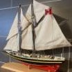
The NRG is an educational organization, dedicated to providing our members with the knowledge to improve the quality of their model ship building. One of the most common problems model builders have is rigging their model. Kit instructions are poor. Often, the materials provided in the kit are improperly sized or the cheapest that the manufacturer could obtain. We all know that blocks are not square! I wanted to develop a project whose purpose would be to teach ship modelers how to mast and rig a ship without having to build a complete hull. This model is a 1:48 scale cross-section at the level of the main mast of a late 18th century British sloop of war, Swallow 1779. To keep the size of the model manageable and eliminate the need for a building board, the hull is cut off just above the waterline. For the same reason, only the center portion of the lower yard and the lower part of the topmast are constructed. Also, because this is a cross-section, certain lines, such as the stays and backstays, are not included. My emphasis will be on demonstrating techniques to improve your rigging skills. Skills that can be used on your next project.
As this was developed as a teaching aid, certain shortcuts and compromises to historical accuracy were taken. Wherever possible, I have used measurements provided by the plans and such authorities as Steel and Lees. I apologize in advance to the master modelers who might criticize my shortcuts. I have kept the use of power tools to a minimum. The only thing that is outside the normal collection of hand tools is a serving machine. The Guild hopes to begin selling this kit in the next few months.
The kit contains all the materials required to complete the model. But I always keep my scrap box nearby for those times when a piece of a contrasting color wood is desirable. I will mention those times as the build log progresses. Also, the build log is made up from the best photographs taken from three builds of this model. A sharp eye will notice some differences in the wood color because of that.
The hull is constructed in typical plank on bulkhead style. There is a notched spine and notched bulkheads. The laser cut sheet of one-eighth inch basswood ply also contains a template for the top and four types of spacers, A through D.
The spine and the frames are assembled as seen below. Frame 1 is installed with the printing facing aft. This gave me the option of painting the exposed bulkhead after construction was completed.
The mast fits in the slanted slot between Frames 3 and 4. To keep the mast vertical, support spacers are glued on both sides of the spine. They will be sanded flush to the spine when the hull is faired.
To prevent the hull from twisting and to strengthen it, spacers are placed between each frame. The three aft spacers are “B”, the next one is “C” and the two foremost ones are “D”. They are placed close to the edge of the frame for maximum stability. The laser char only needs to be removed from the fore and aft sides so that their surfaces are flat. If too much wood is sanded off, I glue strips of paper onto the edge as a filler to prevent distorting the hull.
The hull and deck were faired so there are smooth curves fore to aft. I used a sanding block for this. I did not fair the bulwark extensions (the thin strips of wood above the deck) to prevent them from breaking off. This model has a significant camber to the deck. Sanding sticks help getting into the corners. You can see that the mast supports have been sanded down to match the height of the deck.
Next up is planking the hull.
-
 tlevine got a reaction from Canute in NRG Rigging Project by tlevine - FINISHED
The lower yard is specified on the plans as 41.5 feet long, with a centerline diameter of 9.2”. Just like the mast, the yard is divided into quarters. There are four quarters on either side of the centerline. The two center quarters are octagonal and the yard tapers from 9.2” to 7.8” at the end of the second quarter. Because this is a desktop model, I did not want the yard to extend beyond the side of the hull and made only the middle twenty-five feet.
To make the yard, I started just like the mast, marking the dimensions on all four sides of the dowel. Because this is such a short piece of wood, a template was not necessary. The center octagonal section was made first. Then I wrapped tape around the center quarters to protect them and tapered the outer part of the yards. Finally, I rounded the tapered portions with sandpaper. The drawing illustrates the dimensions.
A pin was placed in the center point of the yard to secure it to the mast. The yard sits at the level of the futtock stave so I drilled a corresponding hole in the mast. You can see the mast hole location in the picture in the previous post, just above the uppermost woolding.
Nine blocks were installed on the yard. The jeer block is part of a pulley system to raise the yard. Its configuration changed several times in the eighteenth century and varied with different sized ships. This configuration is appropriate for a ship smaller than 28 guns in the last quarter of the 18th century. Quarter blocks carry the topsail sheet falls. Clew lines run from the corner of the lower sails (the clews) through the clew blocks. The buntlines raise the foot of the sail for furling and run through the bunt blocks.
The quarter blocks were installed first. The kit will include 5 mm blocks; mine were slightly larger to be the correct length of 5.2 mm. These blocks are stropped with served line. This is my technique. Serve a piece of line that you think will be the right length; on my model this was 1.6”. This is running rigging so the serving thread is natural color. I used Gutterman sewing thread. Leave a long tail of serving thread on either end.
The first step was to make a loop at one end. Untwist a short segment of rope next to the end of the serving on one side and cut the untwisted threads at a 45-degree angle to decrease the bulk. Form a loop, with the untwisted threads laying alongside the served part of the rope. With the tail of serving thread, wrap the untwisted threads and previously served line. In actual practice, the untwisted line would be laced into unserved rope and then the service would continue along the loop, terminating at the throat of the loop. Temporarily seize the block and measure how long the strop should be by wrapping it around the yard. The loop ends do not meet; a seizing will run between the loops to secure it to the yard. Make a kink in the rope to mark the spot. Remove the block and make the second loop the same way. Measure the length of the finished strop so you know how long to make the strop for the other side.
Reinsert the block and secure it with a throat seizing. The seizing is located on the fore side of the mast and the block hangs below the mast. This picture incorrectly shows the legs the same length. Finally, the strop was wrapped around the yard and the two loops were seized together.
-
tlevine reacted to archjofo in La Créole 1827 by archjofo - Scale 1/48 - French corvette
@druxey
@albert
Many thanks for your interest and encouragement, and thanks to everyone for the many LIKES.
In the meantime, the constant rain here in Bavaria is getting on my nerves.
On the other hand, I can spend more time building models again, so I can show you the latest results:
Equipping the fore royal yard - Vergue de petit cacatois
I continued with the equipment of the fore royal yard, analogous to the main royal yard. The fore royal yard still has a thickness of around 2.2 mm in the middle.
The first picture shows the attached tye and parral.
The clew line blocks that had already been produced were then fitted with served block strops and attached to the yard.
This was followed by the final fitting of the yard with the lifts, braces and clew lines. As already mentioned, I will not be attaching any sails to this model. Accordingly, I will later connect the clew lines of the royals to the sheets without the corners of the clews using the toggles.
Last but not least, a picture with the center section of the main yard for size comparison.
To be continued ...
-
tlevine reacted to Gregory in Planking techniques and tutorials and videos, etc.
I think your best bet for understanding the Garboard will be to look at the Half Hull Planking Project..
Talk about the garboard starts here:
I agree the garboard has caused a lot of grief, but I think the main mistake people make is how far forward it should run.
The black strip shows the placement of the garboard. Toni says " The garboard is the only strake with a straight edge. " The image is misleading due to perspective. As it runs forward you have to account for the space it covers on the curved bulkheads.
As I mentioned, where the garboard meets the stem is critical, but if you just lay a straight line , accounting for your plank width, from the stern to the stem, it will be perfect.
The mistake most often made is letting the garboard fall to far aft , which result in planks that curve upward too much as the planking moves up the bow.
Practice making your planks with paper or card before committing your wood stock.
-
tlevine reacted to Siggi52 in HMS Tiger 1747 by Siggi52 - 1:48 - 60 gun ship from NMM plans
Keith, the end is in sight, but I think it takes a lot of time to get there. There are at least a lot of things to do left.
Ian, no with these sticks and ropes I would't play.
Today the Tiger came up from the basement to see some daylight. And both Tigers now are looking how it rains outside.
-
tlevine reacted to Siggi52 in HMS Tiger 1747 by Siggi52 - 1:48 - 60 gun ship from NMM plans
Hello,
when I look at the last likes, some like the picture of Victory's wheels more then that what I have build! It would be interesting why? I had asked before I built it so. But I say thank you to all, for the likes you gave my work.
The carpenters have installed the last two deck beams and also the knees for them. The inspector from the navy board was pleased. So I think, we could go all into the summer vacations.
Except the shipwright. He must look how to build in the taffrail, before the deck could be planked. And may be the carvers, who could start carving the quarter pieces. Steady and slowly we come to the end of this build.
-
tlevine reacted to FlyingFish in Vigilance of Brixham (BM 76) by FlyingFish - 1:32
Well it’s been a while – I’ve been away on an extended fishing trip to the famous limestone Lough Sheelin in Ireland to fish the mayfly hatch. It was, as usual, wonderful. It’s a spectacle of nature, and the big fish appear each year to gorge themselves. For those of you stateside it was the Ephemera danica hatch, much like your greendrakes.
The boats are 19’ made locally and designed for drifting broadside downwind as you cast your fly in front of the boat. The electric outboard is the ‘Ghillie’ helping to adjust the drift around points on onto rising fish. They can’t see you coming if you wear a camo buff…
Here’s one of about 6 lbs and we caught some even bigger. They all went back to grow even larger.
So to work and back on topic – I have some catching up to do on Vigilance.
Frames 30-34
These frames rise above the keelson onto the stern deadwood, as shown by the blue dashed bearding line.
The deadwood is then graded down onto the rabbet to allow the planking to sit flush with the keel.
Frame 34 is the last double frame. Frames #35 - #39 heel onto the horns which themselves butt to the aft face of frame 34. These photos are from the yard:
They started by using ply templates to work out the run of the planking onto the counter before making the frames. Then each massive oak pair was winched into place and secured.
My set-up is shown below here, with frames 29 and 30 being dry fitted. The paper template sets the frame heel position, bearding line position and sheer height. The gantry tape aligns the frames athwartships, and the sliding bevel and set square set the beam width and sheer height at the sheer line accordingly. Temporary ribbands hold everything in line, and help to check the frame bevel is faired. If not then adjustments can be made before fixing.
I've found that making frames this way is risky – if they are not right then maybe they can be faired, but more likely a new frame will need to be made. If I was to do this again I'd leave more margin for sanding.
All for now, whilst I slowly work towards the counter timbers.
-
tlevine got a reaction from Nirvana in NRG Rigging Project by tlevine - FINISHED
The futtock shrouds are attached to the futtock stave below and the futtock plate above. An eye with a thimble is spliced into the upper end of the futtock shroud. A double hook connects the shroud and the futtock plate.
To make the stropped thimble, I took some line and unfurl the end. Using a blunt needle, I made an opening in the line approximately the circumference of the thimble away from where the unfurling stopped and fed the unfurled end through the opening. Once the line has been passed through the opening, the opening will naturally retwist itself. A piece of brass tube (the thimble) was inserted into the eye and the splice was glued. The thimble was blackened after it was stropped because handling would have caused the patina to rub off.
The brass tube is slightly wider than the diameter of the rope. To keep the thimble from falling out of the splice, I placed it on an anvil and tapped each open end with a center punch. This added a slight lip to the thimble. The double S-hooks are 1/8” long and were made from 24 g wire, using round-nose pliers. The picture shows them attached to the futtock plates.
The futtock shroud was attached to the futtock stave by wrapping around the stave and securing it to the lower shroud with two round seizings. In the drawing, the futtock shroud is shown in red and the lower shroud in blue. After they were installed four rows of ratlines were added.