

tlevine
-
Posts
2,020 -
Joined
-
Last visited
Reputation Activity
-

 tlevine reacted to archjofo in La Créole 1827 by archjofo - Scale 1/48 - French corvette
Addition of the lifts of the lower yards - Balancines de basse vergue
Usually, as can be read in the specialist literature in the book "Manuel de gréement" by F. A. Coste, Paris 1829, the lifts of the lower yards were secured using tackles, each at the height of the 2nd shroud of the respective lower mast. This is also how J. Boudriot illustrated it in the monograph on La Créole, as shown below.
Source: Monograph La Créole by Jean Boudriot
On the original Paris model, I identified the lifts as shown in a diagram:
Source: Musée national de la Marine de Paris - La Créole
However, no tackles can be seen there. The lifts were simply attached to the upper part of the tackle ropes at the height of the 2nd shroud. This easier handling of the lifts could have been due to the size of the ship, or is it a simplification by the contemporary model maker?
We will never be able to find out.
However, I find this type of seamanlike handling of the lifts rather impractical and have therefore decided to use tackles, whose ropes can then be properly secured on the inside.
I wouldn't exactly describe my model as a "pile of evidence" as a dear forum colleague once described his project. However, I have implemented a large number of details on the model that seemed plausible to me after research. I cannot provide 100% proof of this, but solutions that actually existed and generally fit into the temporal and country-specific context of La Créole.
In this respect, I will basically attach the lifts as follows:
Source: Excerpt from Atlas du Génie Maritime annexe N.1, Pl. 20
However, I will only use a double block at the top and a single block at the bottom for the tackle.
To be continued...
-
tlevine reacted to Chuck in Sloop Speedwell 1752 by Chuck - Ketch Rigged Sloop - POF - prototype build
Although time has been limited for me for working on the model, I have been making progress. I have finalized the way I will do the deadeye strops and chainplates. These are all laser cut and makes life a lot easier. Once designed the actual construction time was non-existent. It took seconds to add the strops.
This was just a test run but an improved version of those I developed for the Winnie. They really do just slip right on.
There will be two sizes of deadeyes and strops. The chainplates will all be the same more or less. They are laser cut and 1/16" wide and about the thickness of was brass straps would have been. You must do a little bit of work on the straps but not much. The hole for the little brass pin must be drilled through the bottom of the strap. I used a "67 drill bit. Its acrylic so this was so much easier than drilling through brass. At the top of the strap there is a little "hook" shaped on the end. This will fit into the bottom of the strop after the deadeye is placed on the channel. The width is 1/16" as I mentioned which is a tad wide for the hook to fit in the strop bottom. So this was filed narrower on both sides. This was done just at the "hooked" part of the strap which fits into the strop which you can see above. They are cut from black acrylic so no need to blacken but you may want to weather them a bit to "metalize" them in appearance.
This is what they will ultimately look like on this sectional model which was really fun to make of the Speedwell. The deadeyes are my new resin 3D printed ones. These are the color of Swiss Pear. I will be using these on my model. You can see how nicely the straps and strops worked out. Also have a look at those molding strips on this sectional model. The fancy molding. This was a new test and also laser cut. I will be using them on the sectional model projects.
The inboard side. The entire sectional test is completed. I just have to add and rig one cannon. That was the whole purpose of this mini-model. It is to be used to help teach building techniques for cannon carriages and the their rigging. My local club members in NJ will be using it as a quick and hopefully fun group build as a tech session taught by me. It should be fun. There will also be some gun crew figures added.
This is a close up of the molding test. I know how some guys hate creating scrapers to make their own molding. This will save the guys a lot of time. I am thinking about offering these as stand along optional moldings for the big project as well. Or for any model really. There are three profiles. 1/16", 3/32" and 1/8" wide. All three are 1/32" thick. They are laser cut on Syrenite. They can be used as is but I do recommend sanding the top and bottom edges to soften them and round them off. Although the color as is looks great. I like to enhance it by wiping some Gel Stain on them and then wiping it off. It settles into the grooves and help highlight the profile. It deepened the color a bit as well. You know...just like I handle making the carved resin figurehead and stern figures look like boxwood. It takes about 2 minutes to do. Then wipe off the excess. The more coats the deeper the color depending on your preference. I think folks might like the option to buy these molding strips regardless of the project. So expect soon. But let me know if you are interested as I wont waste material and time if there is little interest. Volutes and scrolls should be easy to add to this line of products as well although every model uses a different size scroll-work. So maybe I have to thing about that. It can also be painted and as I said sanded easily.
-
tlevine reacted to Stuntflyer in Sloop Speedwell 1752 by Stuntflyer (Mike) - Ketch Rigged Sloop - POF
Just finished up the bench lockers. I really enjoyed making them
Mike
-
-
-

 tlevine got a reaction from James G in Question- Seawatch Books Order - Need Help!
I received a shipping notice today.
-
tlevine reacted to Rustyj in Sloop Speedwell 1752 by Rustyj - Syren Ship Model Company - 1:32 Scale - POF Sloop
Well I've completed the bow timbers and rough faired it. I was dreading this as I've never been really successful with this part of the build, but I managed to get through it and everything still lines up. Chucks instructions and etched reference lines along with Mikes log really helped. Now I'll move on the aft cant frames which is number 2 on my dread to do list. 😂
-
tlevine reacted to archjofo in La Créole 1827 by archjofo - Scale 1/48 - French corvette
@matiz
Hello Tiziano,
thank you for your nice comment.
I'm particularly pleased to receive such praise from such a fantastic model maker.
Of course I would also like to thank everyone else for the LIKES.
Hello fellow model builders,
today I would like to present to you my new video about the yards and spars of the La Créole.
I hope you enjoy it: LINK
-
 tlevine got a reaction from Bob Fraser in Period Scale Model Masting and Rigging Tables
The updated version has been added to the Resources section.
-
 tlevine got a reaction from Ryland Craze in Period Scale Model Masting and Rigging Tables
The updated version has been added to the Resources section.
-
 tlevine got a reaction from Kris Avonts in Period Scale Model Masting and Rigging Tables
The updated version has been added to the Resources section.
-
 tlevine got a reaction from mtaylor in Finishing Pear wood
I use Danish Oil for all of my models. My Hannah was made from pear (not swiss pear). It darkened the wood slightly but brought out the character of the grain.
-
tlevine got a reaction from mtaylor in Period Scale Model Masting and Rigging Tables
The updated version has been added to the Resources section.
-
tlevine got a reaction from Ryland Craze in Finishing Pear wood
I use Danish Oil for all of my models. My Hannah was made from pear (not swiss pear). It darkened the wood slightly but brought out the character of the grain.
-
tlevine reacted to dafi in methods for serving a thin rope
After many trials with real serving and other methotds even using wire I came for my Vic 1/100 to imitating the serving with white glue.
Three layers of white glue, smoothed with spit and fingers, and then applying black paint. In my case the best result for the real thin ropes and also good in the time/effect ratio 🙂
XXXDAn
-
tlevine reacted to FlyingFish in Vigilance of Brixham (BM 76) by FlyingFish - 1:32
Update
Thanks for the views, comments and 'thumbs up'!
Well time in the shop has been limited recently; a prolonged spell of dry settled weather has allowed me to get on with several jobs outside that needed doing – a pair of new shed doors, clearing out downpipes and fixing gutters etc. Not to mention a few bonus fishing trips. All unexpected but very welcome.
A change to colder weather brings me back on task.
During this time, Vigilance No. 1 took on a mild twist. That’s what comes of leaving a framed boat un-planked for too long, despite leaving her well held in the building jig.. It wasn’t much but would have thrown things out of kilter later on, so took the time to fix it.
It necessitated taking off the shelves and clamps, stringers and the haunch timbers, hitching her back into shape and re-gluing. A pain but it’s done.
I will say that C/A glue is actually a whole lot easier to unstick than PVA – a quick wipe with acetone on a brush. Leave a few minutes than pry carefully apart.
Anyway, onto the next step.
A preamble to planking. [Skip this section if you want to avoid my inane ramblings – I’m simply planning aloud].
I had naively assumed that I could plank both versions simultaneously. A moment’s thought shows that version 1 (cutaway); ‘plank on frame’ and version 2 (fully built); ‘plank on station or bulkhead’ requires different approaches, even if the intention is that the resulting hulls will look the same.
Even if the planks are identical, the positions of the frames (V1) and stations (V2) are different, and hence the ‘tick strips’ or whatever needs to be original to each version.
Additionally, version 1 has frames at 6° to the heel, whereas version 2 has stations perpendicular to the keel.
I think it will become confusing to try and log these together, so let’s concentrate on what’s common to both for the moment.
The method described is that used originally, and by the shipyard, so far as I can see.
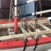
Once the frames are roughly faired, battens are placed at sheer and at intervals down the stem to the rabbet line on the keel, as shown, all adjusted to create fair lines.
These create bands of planking to be filled in stages, starting with the garboard & sheer. The distance between the battens is divided to give the planking width in each band, although in practice, planks are put on at each ribband position first, then the gaps filled with shutter planks spiled as necessary.
The position of the battens is decided when designing the line-off plan, and by consideration of what they do to the plank width. Convention is that a plank should not reduce by more than half it’s width, and that where possible stealers etc should be avoided. This whole subject is vast, and open to all sorts of interpretation. I don’t pretend to know very much about it, but the principles are straightforward enough – ‘do what looks good and works with the wood’. In other words, keep it fair and avoid too much edge setting. There are many excellent tutorials around, including several on this forum to which I can add nothing.
The simplest method is to measure the length of each station’s girth from sheer to keel and divide it by the number of planks required. This gives the width of each plank at each station. However, for some hull shapes (including Vigilance) this may not work when the lines are pinched or stretched at either end of the boat, and the widths are either too narrow or too broad, necessitating stealers, broadstrakes or suchlike.
For such boats one method involves drawing one or more lines along the hull, made by stretching a string along its length so that it proscribes the shortest path from stem the stern. A dead straight plank lays perfectly on this 'Magic' line and will need no edge setting, because it is a right-angles to the hull at every point. This becomes the ribband that defines the point above which planks are identical in shape (other than the bevel). By which I mean they will have the same width at each station. Below this line the planking requires a different approach due to the more acute shapes below the waterline. (Credit due to Mr Sauzedde for the explanation).
So back to practicalities and how to line off Vigilance, starting with what we know about her.
The photograph of Vigilance at Newlyn shows her with 21 planks not easily discerned, edged yellow below. Planks 10,11,&12 at the turn of the bilge were thicker, as were the three topside strakes. Strakes 1 – 7 were wider over the deadwoods at the sternpost to allow the narrower planks to fall more fairly under the counter.
Over the years and several re-plankings later, she still had 21 planks when she arrived at the yard in August 2023.
Planks10 11 and 12 were thicker, as were the top three strakes. Planks 8 and 9 reduced into one plank at around frame 5 or 6 on both sides at some time – unsure if this is original, but to be avoided in the plan.
Planking was 2 3/8” thick ; planks 10, 11 and 12 at the turn of the bilge are thicker at 3”, as are the three topsides.
The garboard is 7” wide at the midpoint frame 18, and the sheer and the four topsides below it are also wider than the bilge band at the midline by about an inch.
As mentioned, the planking widens over the aft deadwood section, another shot of this below.
As the planks come under the counter at the stern they first terminate onto the sternpost, then as they go above the sternpost onto the stern tube each butts the opposing plank at the centreline, as shown in the image. Plank 8 marks the intersection of the stern post and the counter, and is a good place to consider marking a fair line above which the planking is all of similar widths at each section, as previously described.
The battens below show how the planking bands work under the counter, and how the planks butt above the stern post.
To create a fair line from the bilge to the intersection of the sternpost and stern tube it is necessary to widen the first 6 planks above the garboard from the keel as they run over the deadwood and up the concave surface of the frames.
This can be seen in the final image below, the bottom edge of plank 7 marked.
So the idea is to mark the position of the batten at the sheer and the next ribband on the line just described joining the 7/8 planks junction at the point where the stern post enters the counter planking at the stern tube. It’s a bit arbitrary; one could equally have used the planks 8/9 boundary (as I think the yard did), but keeping the seven lower planks together works well I think.
The last decision is where to terminate this line at the stem.
The planking has equal widths from the garboard to the sheer at the stem, so this really takes care of the last position we need to map out the first band of planking.
Using the sectional plans of the frames at key points the position of the top of plank 7 (as determined by division of the frame length) can be mapped onto the boat in CAD. Putting all this information together we can plot the batten line we need as shown (line with dots along it). Below these the lower 7 planks are faired.
Interestingly when checked on the model this line does correspond nicely to the ‘magic’ line where a plank sits straight without edge setting.
I found a picture of plank 8 being fitted and you can see it needs no bevel and little or no edge setting. Lou would be pleased.
Above this line planking is divided equally into further bands using battens.
From the CAD plans it’s possible to measure the distance up each frame that the planks cross, at least at key points like the top of plank 7 and the other batten lines. The ability to accurately measure the length of a curve on a plan is an unexpected bonus of using CAD.
These can be transferred onto the model with a bit of care, and planking can progress from the garboard to the ‘magic line’ then downwards from the sheer. I may well have another band somewhere in the bilge area, but I want to avoid having to spire in more than necessary.
So that’s my happy task ahead.
If you’ve followed all this so far you deserve a medal. Or like me, a nice little glass of calvados, a momento of a recent trip to Brittany.
All for now!
Widen planks in this area
-
tlevine got a reaction from mtaylor in Question- Seawatch Books Order - Need Help!
I received a shipping notice today.
-
tlevine reacted to Rustyj in Sloop Speedwell 1752 by Rustyj - Syren Ship Model Company - 1:32 Scale - POF Sloop
I've finished with the forward cant frames and now it's on to the bow timbers.
Chuck etched taper reference lines on both sides to help get the correct shape. A lot of shaping with an x-acto and sandpaper.
The first pair are done and ready to go on the model.
-
-
-
tlevine reacted to Alan Cabrera in Came across tool website that might work for many of us......
Definitely. It’s one of the things I love about this specific community is its ethics.
One thing to be aware of is that ICANN does not verify the contact information, iirc.
-
tlevine reacted to druxey in Deck lines on sheer plan
This is a problem with modern re-drafted plans - unless it's stated one doesn't know! Contemporary plans show both the line of beams at the side and centreline. In this case you don't even have a line of ports to give you a clue. The Royal Museums Greenwich hold a sheer and profile of the Pandora class:
https://www.rmg.co.uk/collections/objects/rmgc-object-83477?_gl=1*1l5sqqk*_up*MQ..*_ga*NTU5MTEyMTE3LjE3MzE2NzU5NTI.*_ga_7JJ3J5DBF6*MTczMTY3NTk1MS4xLjEuMTczMTY3NTk3NS4wLjAuMA..*_ga_4MH5VEZTEK*MTczMTY3NTk1MS4xLjEuMTczMTY3NTk3NS4wLjAuMA..
This would be a more reliable starting point for you.
-
 tlevine got a reaction from GrandpaPhil in Beginner - Rigging Tools
Take a look at the build log for the NRG rigging kit. The second fanciest tool is a fan showing the distance between ratlines. The two things you need to acquire are information about which lines are served and a serving machine. Of the ones commercially available today, Syren's is the best by far.
-
tlevine got a reaction from GrandpaPhil in Beginner - Rigging Tools
I find size 10 crochet hooks to be very useful with rigging. Readily found in sewing stores and Amazon.
-
tlevine got a reaction from mtaylor in Pegasus by hdrinker - 1:48 - POF - Swan practicum
Like your taste in moral support. I would suggest going low tech... Hold the material in your hand and shape it with a file.