garyshipwright
-
Posts
939 -
Joined
-
Last visited
Content Type
Profiles
Forums
Gallery
Events
Everything posted by garyshipwright
-
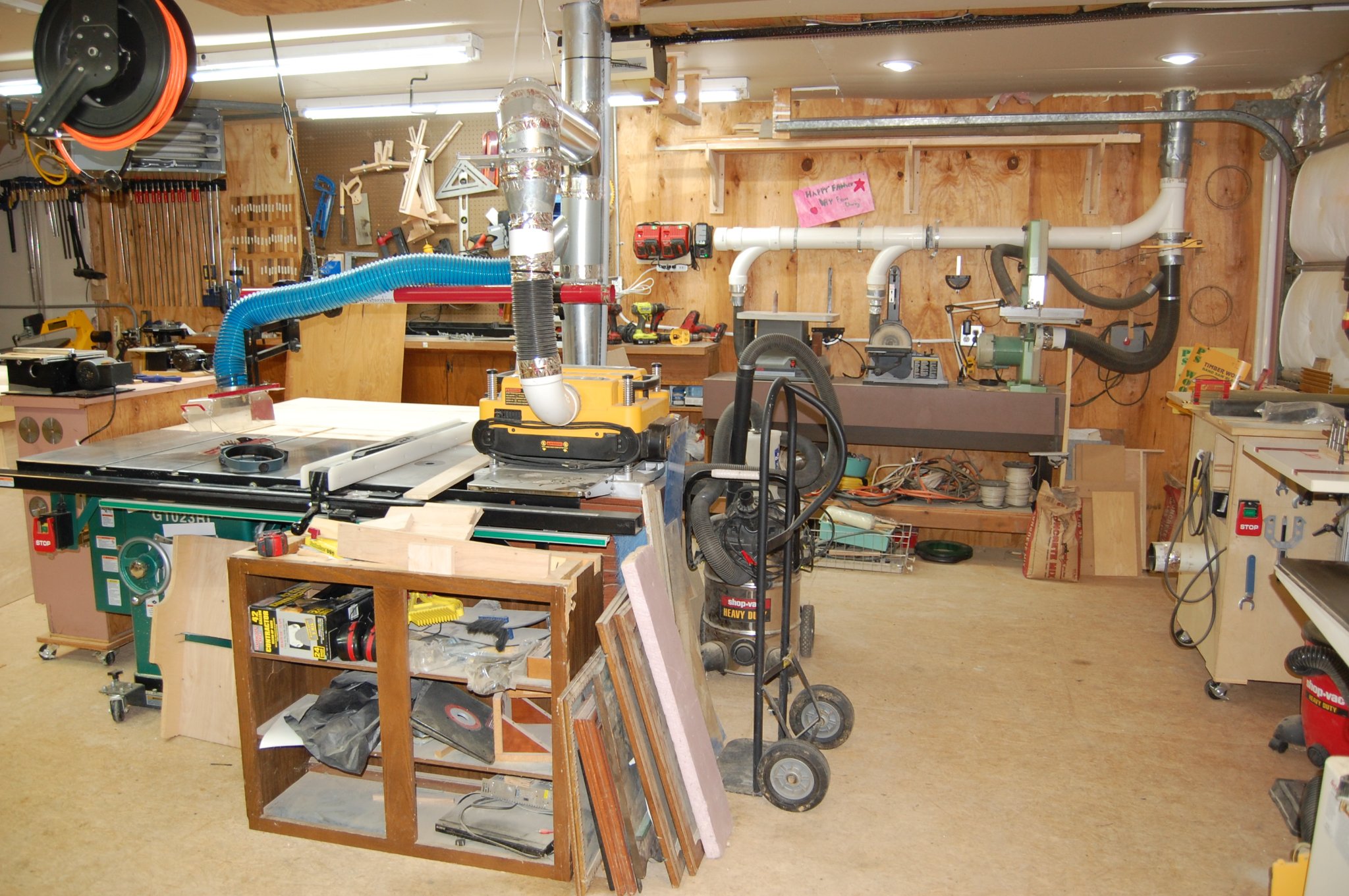
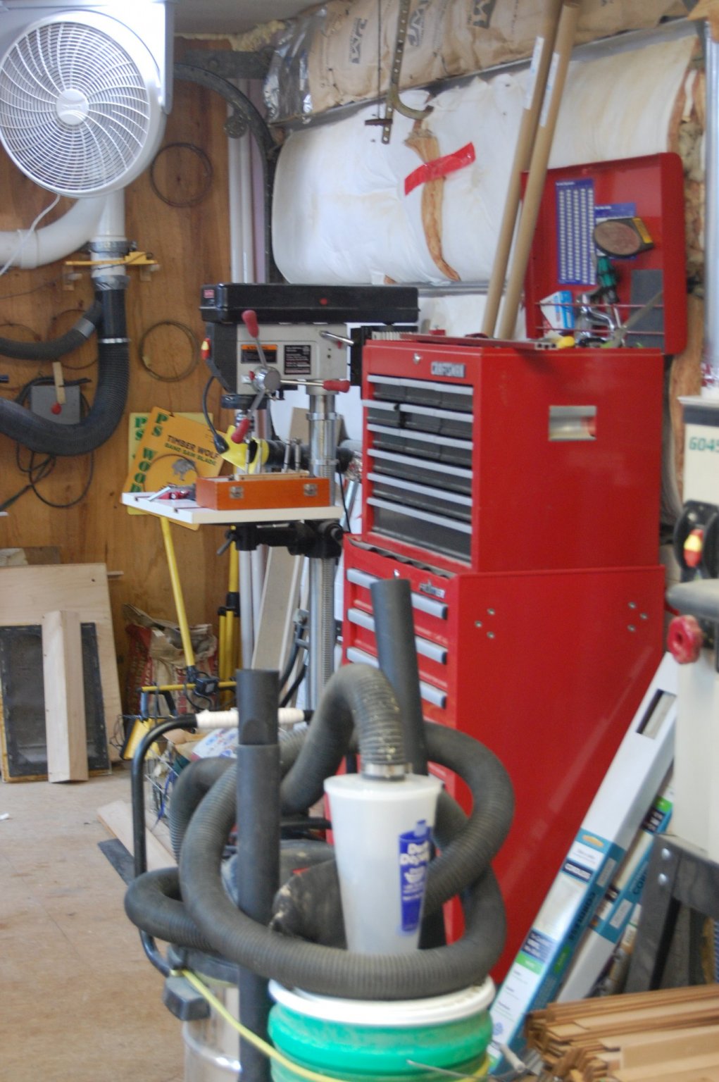
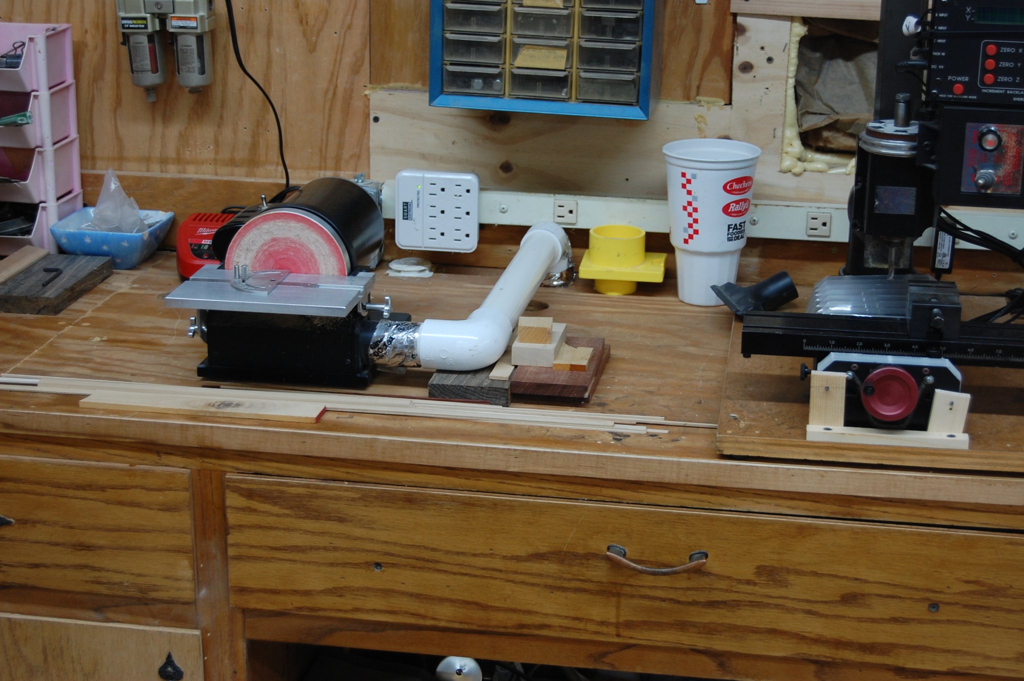
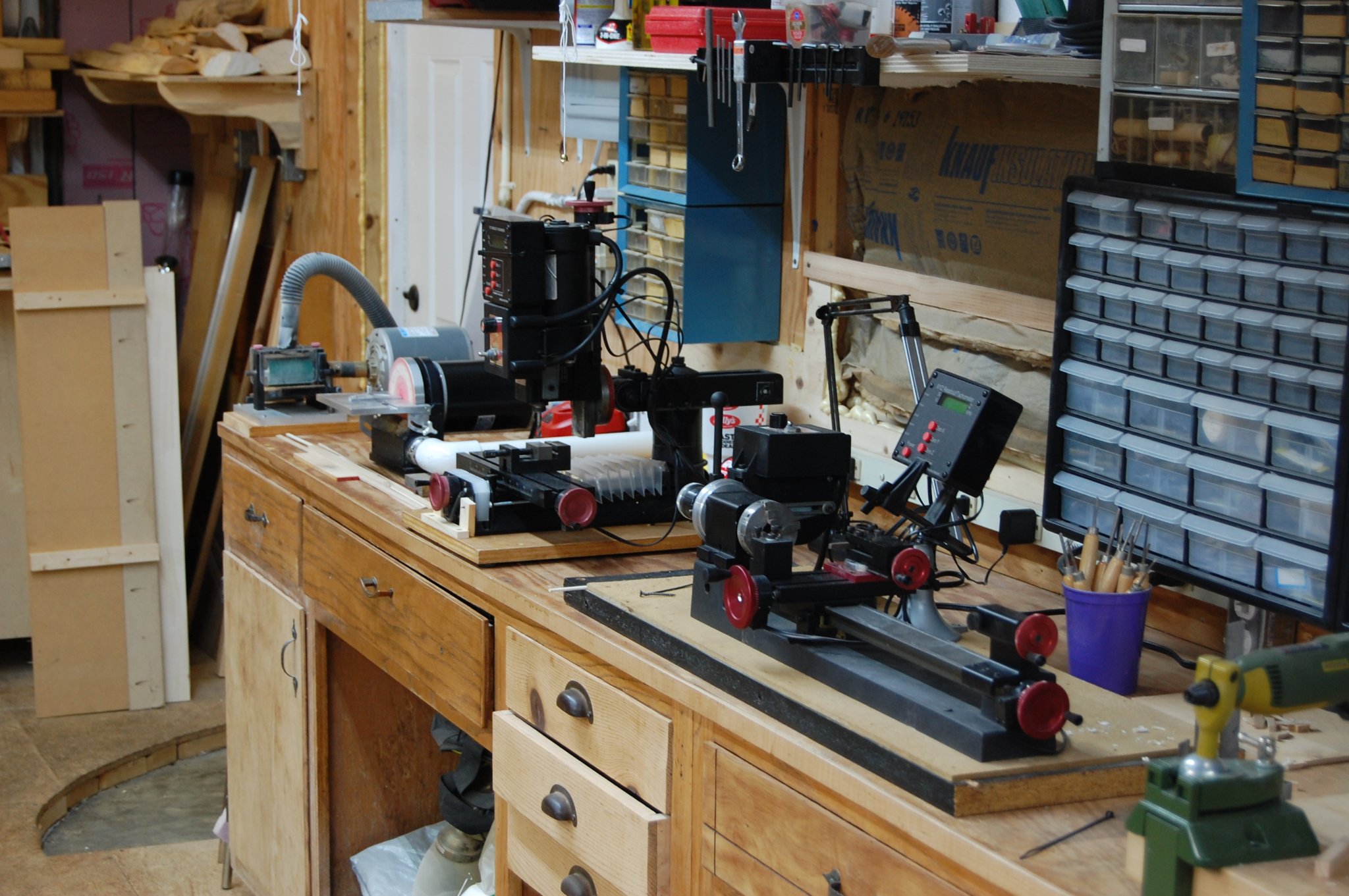
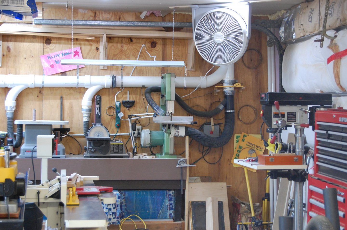
 Hi Hakan and you may sir. I have a 10 inch bandsaw and two small table saw's a Byrnes and a Preac saw and would be lost with out them. The band saw is a Inca that is probably 20 years old give or take 5 year's that I use to rip stock down to a size that can then be used on the mini table saws. If you look to the left of the main table say you will see the Byrnes and Preac saw and on the right side you can see the green band saw. Hope that answer your question sir. Gary
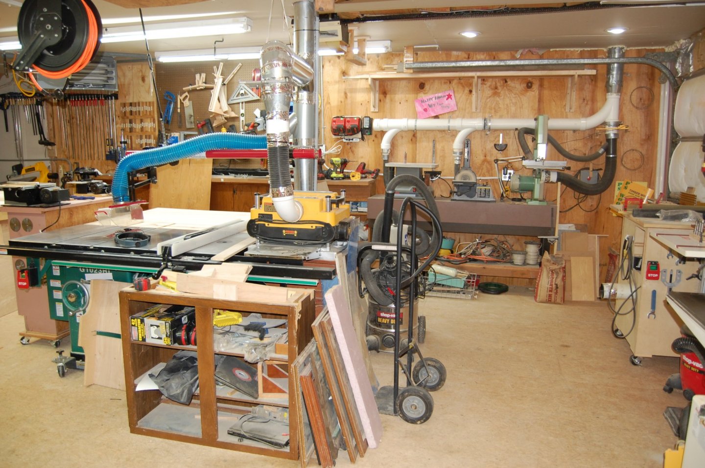
- 835 replies
-
- 11
-

-
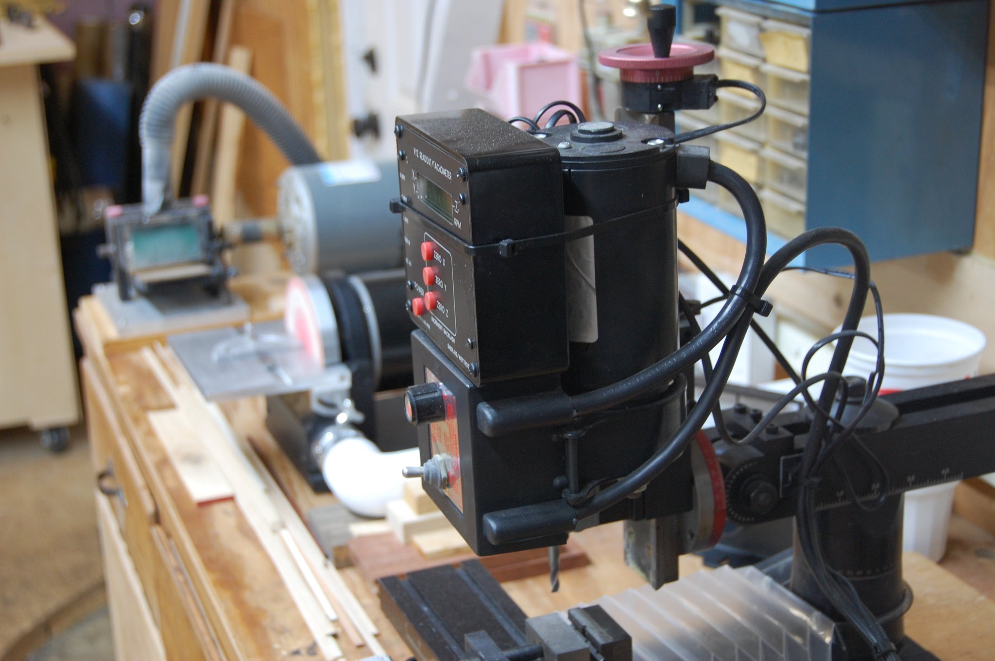
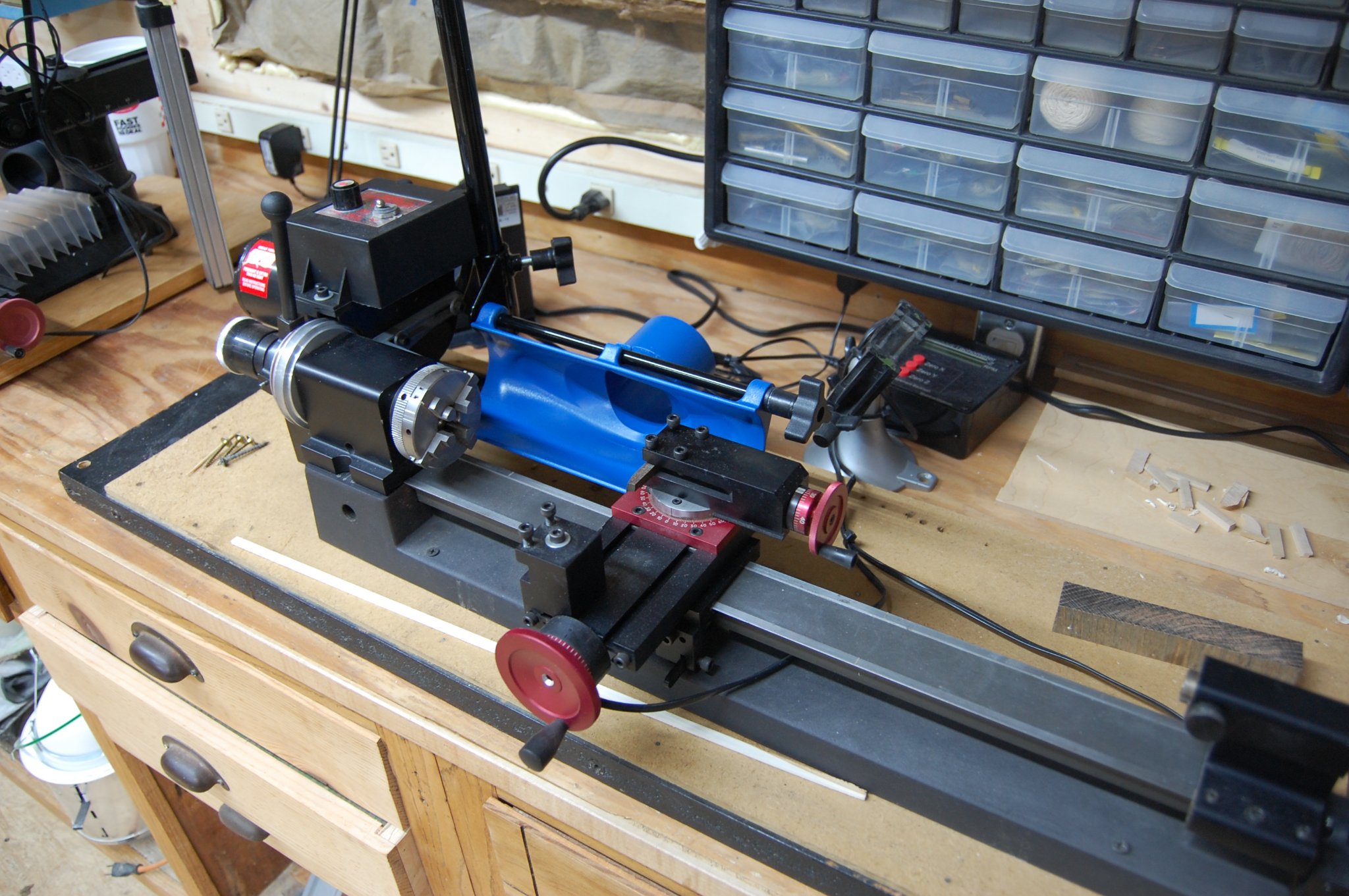
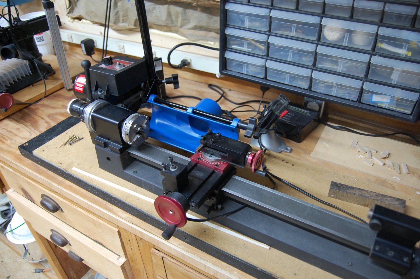
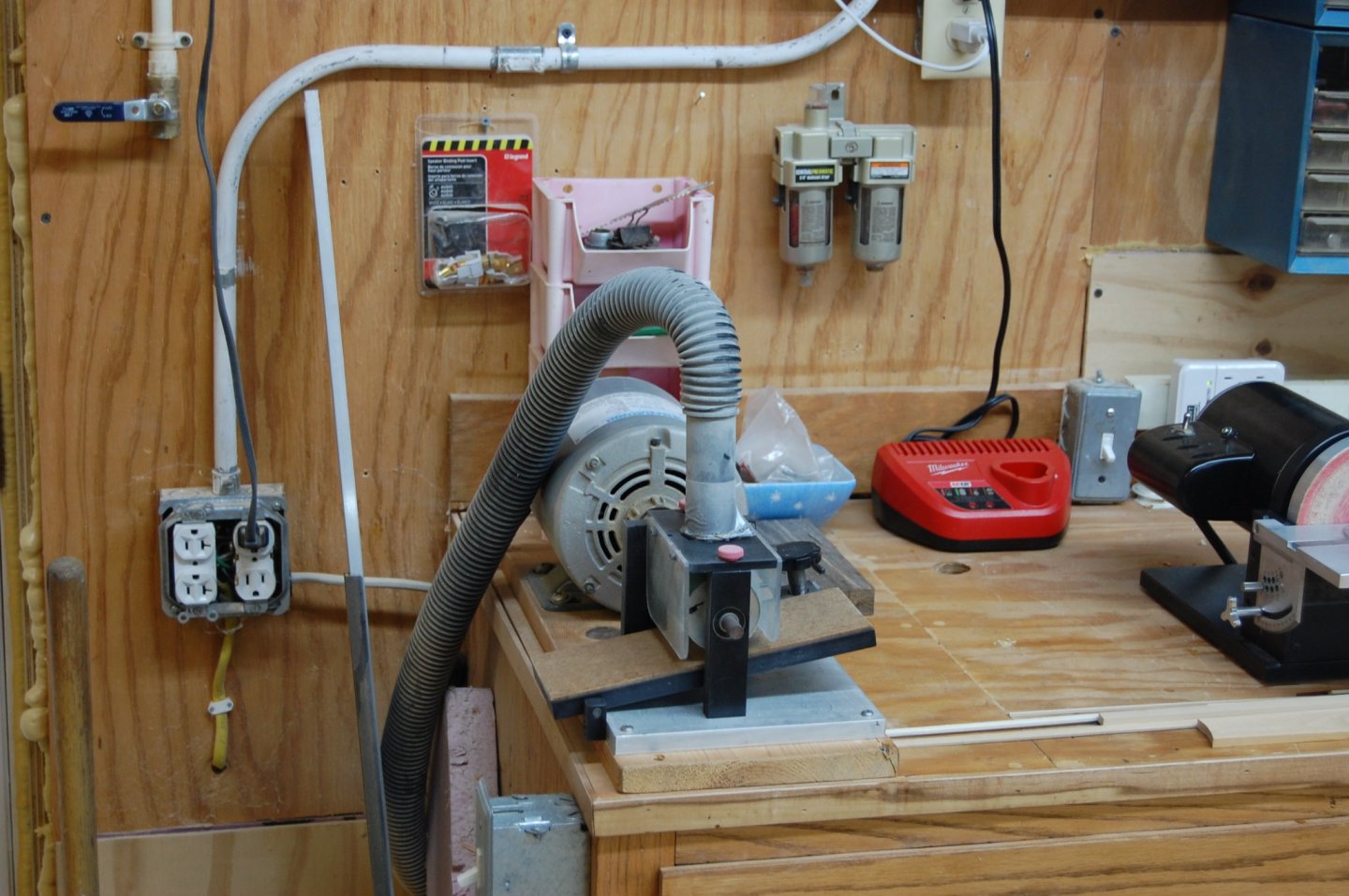
Hi Mark i just used a cable tie or two and just strapped it to the motor. Vibration and heat from the motor doesn't get hot enough to affect the DRO. Question, do you have dust collection hooked up to your lathe or mill? am looking for ideal's to hook up some thing and maybe some one can point me to where I can see some ones hook up. I purchased a dust set up for my lathe from Rockler and am working on a set up for both the lathe and mill as we speak but nothing set in stone at the moment.

-
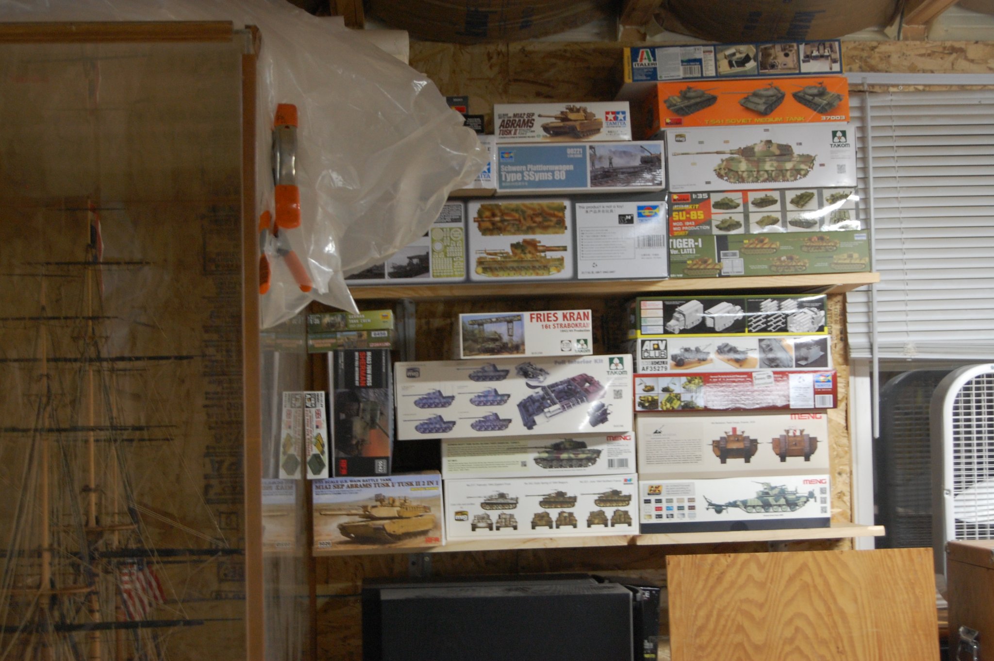
Hi Harvey. Am not sure but it may be the 1/72 space shuttle with booster's by Mongram or the Tamiya 1/12 scale Formula 1 MP 4 6 Honda made made i believe in 1991. It seems a little on the hard side to figure out when the kit was made but will take a second look. Gary
-
Nicely done Alex and agree with druxey completely. Gary
-
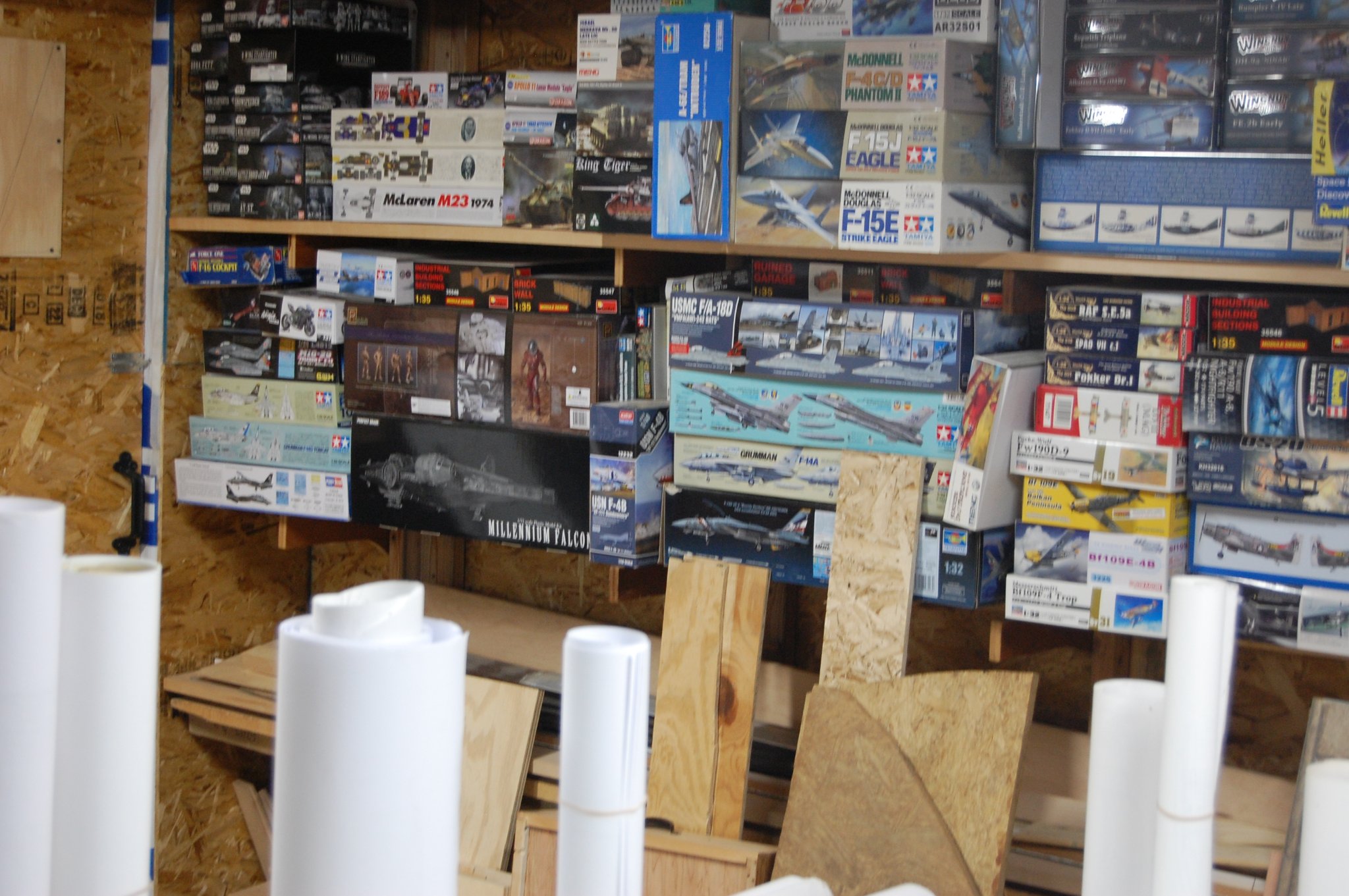
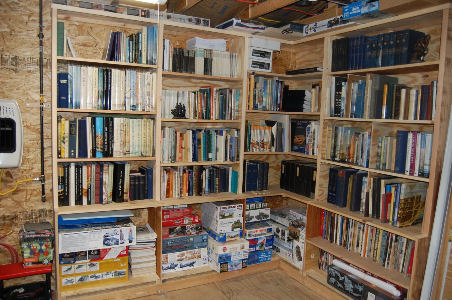
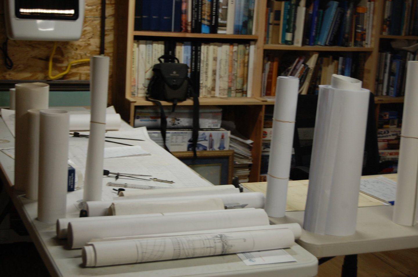
Hi Guys and am sorry on the slow response. Christian I really like WNW kits and was sadden when they went out of business. Now it seems the only place to get one is on Ebay and they are asking for almost three times the amount. I did get the Meng kit of the Red Baron plane the Fokker which I do believe comes from WNW. A good kit with lots of detail. Druxey that dust collector has been a life saver helping cut down on the dust in the shop and since all of the wood is cut in the main part of the shop should help's me keep it out of the back room were I have a few books such the swan books. In fact I have the original monogram that was sent out to the members in chapter's. . Only thing missing from them is a autograph. Hum I wonder. Thanks Mark I still work on plastic models and as you say it still takes me a couple of months to build on. Problem with me is I try to add after market parts to just adds on to the build time. Hi Clay. Your very welcome sir and all you have to do is just ask. Hi Martocticvs and thank you, she is getting there.
-
🙃🙃 What, what holes. Dang it, I was hoping no one noticed. Ok back to building.
-
Some Mark just call it giving a really good friend a hard time and one that has a very good sense of humor but you way of thinking sounds better. Most of the time I have that same condition called complexititus. Now please don't ask me to say that word, did good just typing it out. Gary
-
Shoot druxey mine was a model T. I drill a hole the size of the trunnion, cut the piece of wood in half at the hole and then taking that same bit, pressing the bit down on top of the copper strip over top of the half hole and I now have a cap square for my cannon. Very interesting Mark. As they say, more then one way to skin a cat. Gary
-
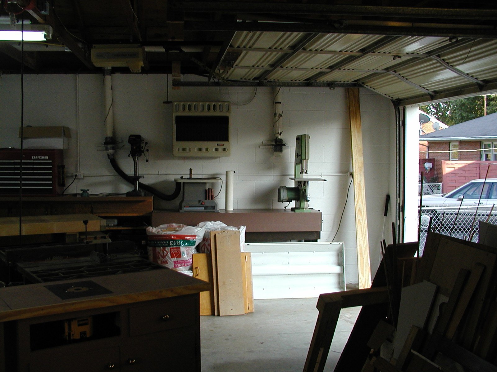
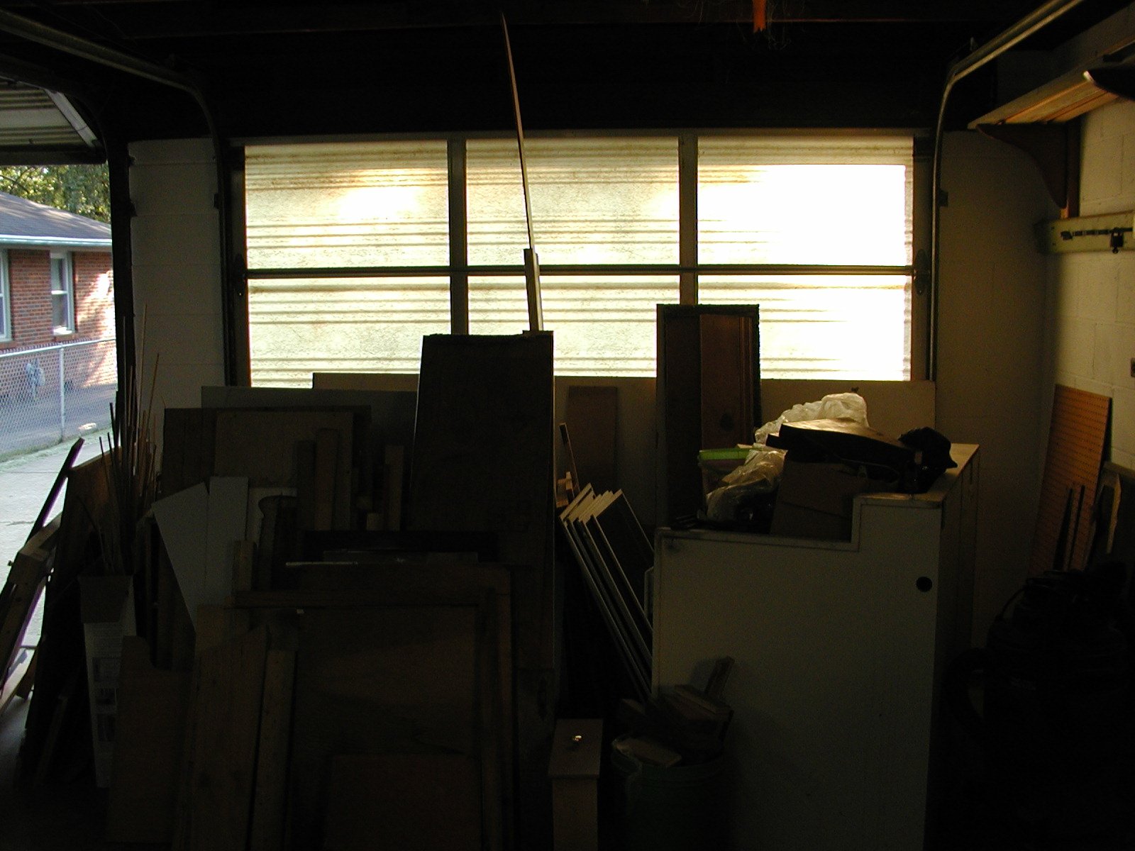
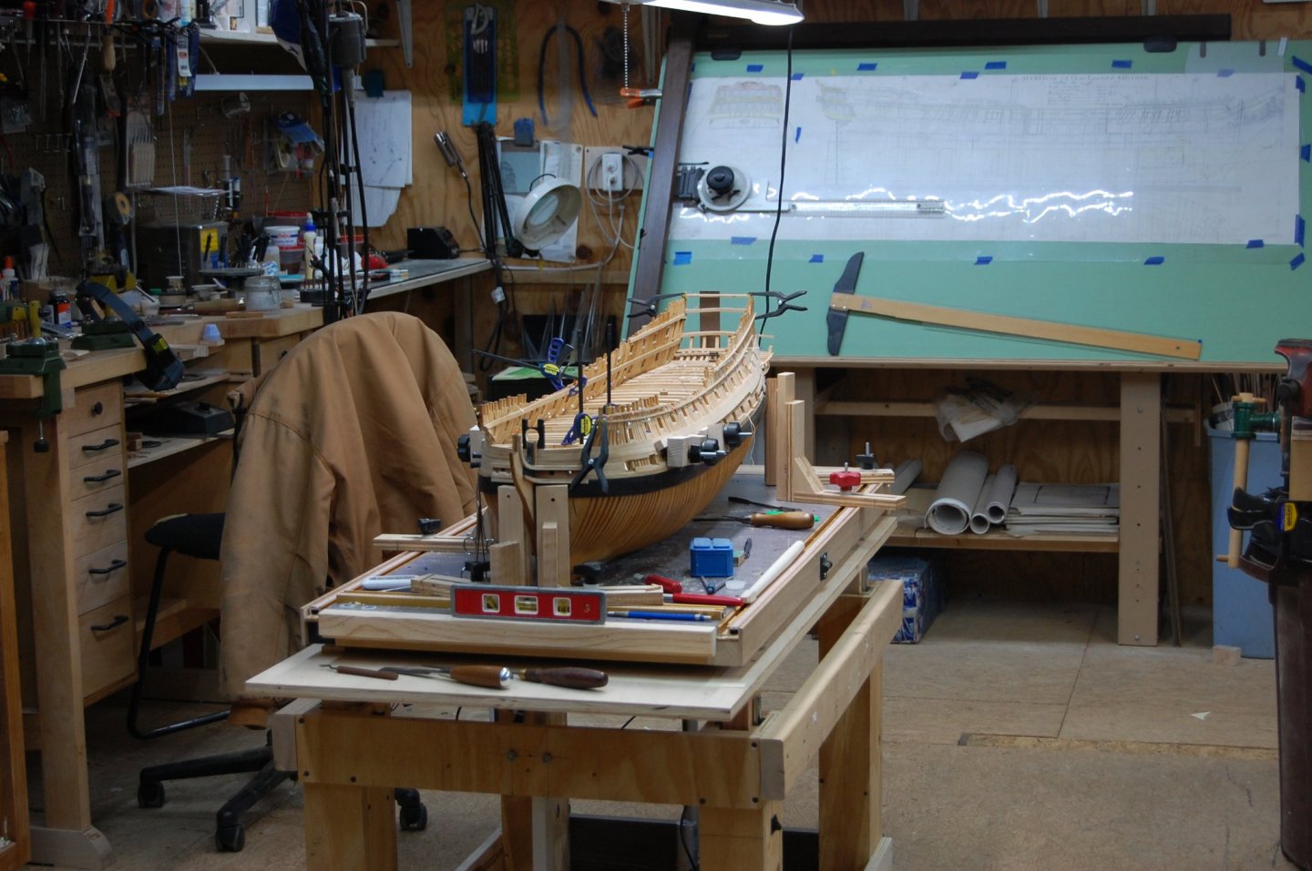
Thanks Guys. It has taken me a few years, but would you believe me if I told you the shop is alive. I know, sounds kind of dumb, but it has been changing since 2007 when we moved in. I have a couple of photo's showing the way it looked when we moved in compared to how it looks today. Looking at others workshop's and lay out helped me come up with the best lay out. The one thing that has really made the shop a nice place to work is when I added on the the 16' x 15' foot extenson. Am planning on adding internet and a computer to the back room, so I don't have to run in to the house when ever I need to look for some thing on the internet. Thanks again guys and happy New Year. Gary


- 835 replies
-
- 14
-
-
Mark couldn't you do the same thing that I was talking about for holding the cannons. Take a flat piece of wood and make it the same size as the bottom of the standards with a couple of holes in it. Then you could mark the bottom of the standards, drill the holes and put peg's in them. At the same time use that same flat piece of wood with the holes in it to mark the lay out of the holes on the beams. I know you will come up with some thing. Happy New Year Mark. Gary
-
Nice job Mark. Just one question sir and was wondering what your using to make your bolt's? Thank you for a real treat. Gary
-
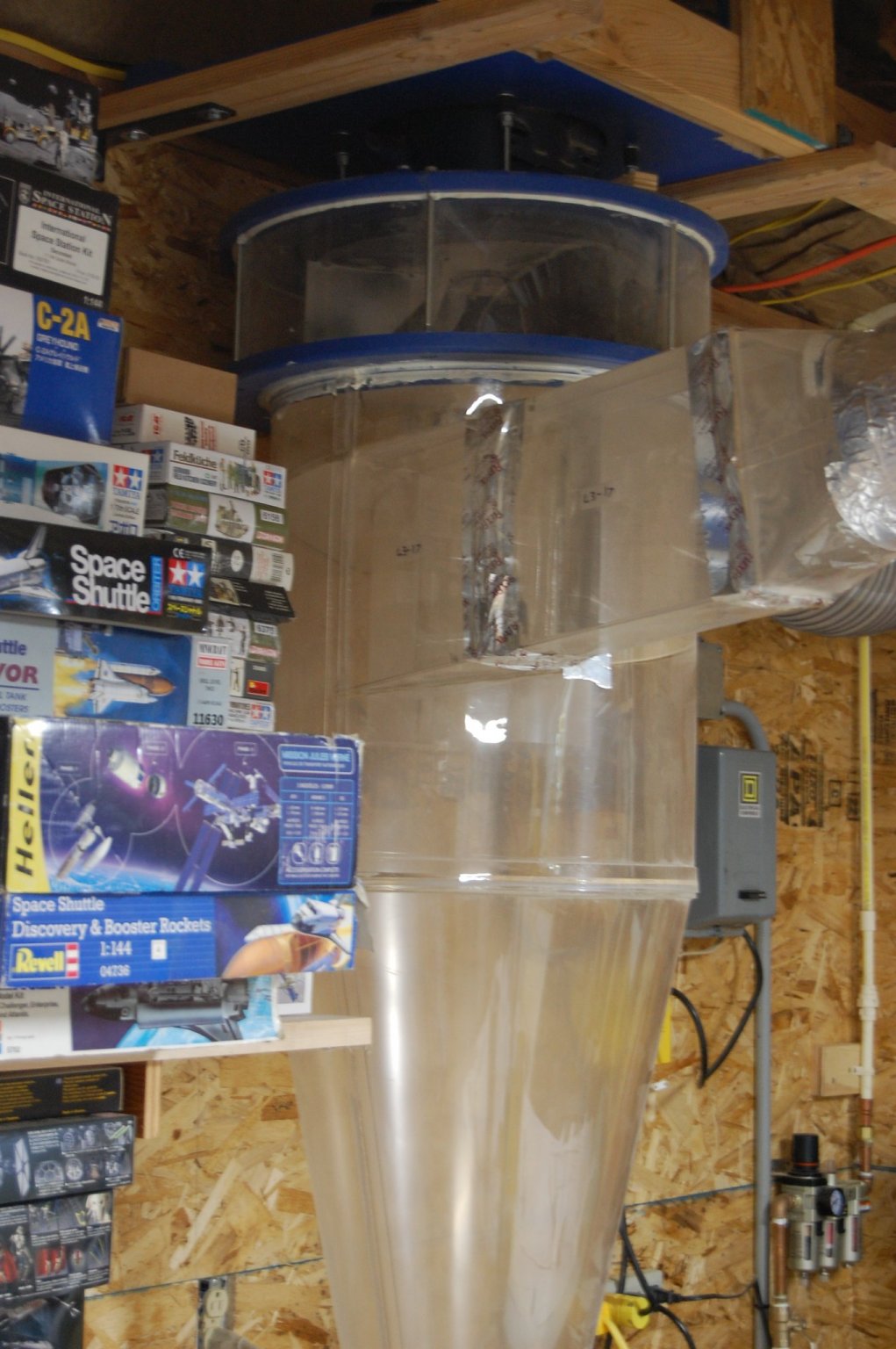
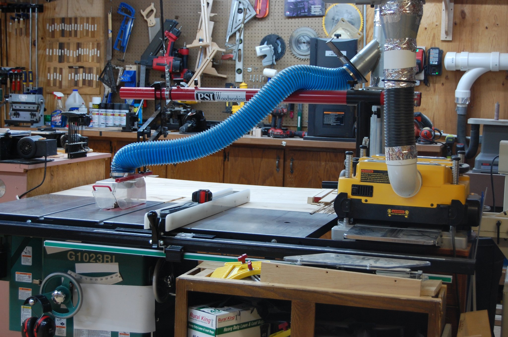
Hi Clay and thank you for your kind word's. I have a large cyclone in the back room that has been piped in to the main part of the shop which help's keep down the saw dust down along with several smaller vacuum cleaner's under neith the smaller tool's. Even with them I still have to use a vacuum cleaner to pick up the stuff on the floor. Much better then sweeping up which just pushes dust around the shop. It is a on going war through and ever week I go through the shop and put tools and items were they belong and the vacuum up the shop. It does get messes at times which makes finding things a little on the hard side. I add some photo's showing how it looks now. Once you get in to building your Warrior if you have any question let me know and I will see if I can find a answer for you. Once again thank you.


- 835 replies
-
- 11
-
-
Mike, Dremel makes a 90 degree attachment for their motor tool and cost is about 30 dollars. They also make a shaft tool that also has a 90 degree attachment but am not sure the cost on that one. I own the motor tool attachment and comes in handy for drilling hole's on the in side of the hull and comes in real handy for drilling all of those holes. Are the straight most of the time no but that's ok, like somebody side they wasn't straight in real life either. Gary
- 969 replies
-
- 4
-
-
- hahn
- oliver cromwell
- (and 1 more)
-
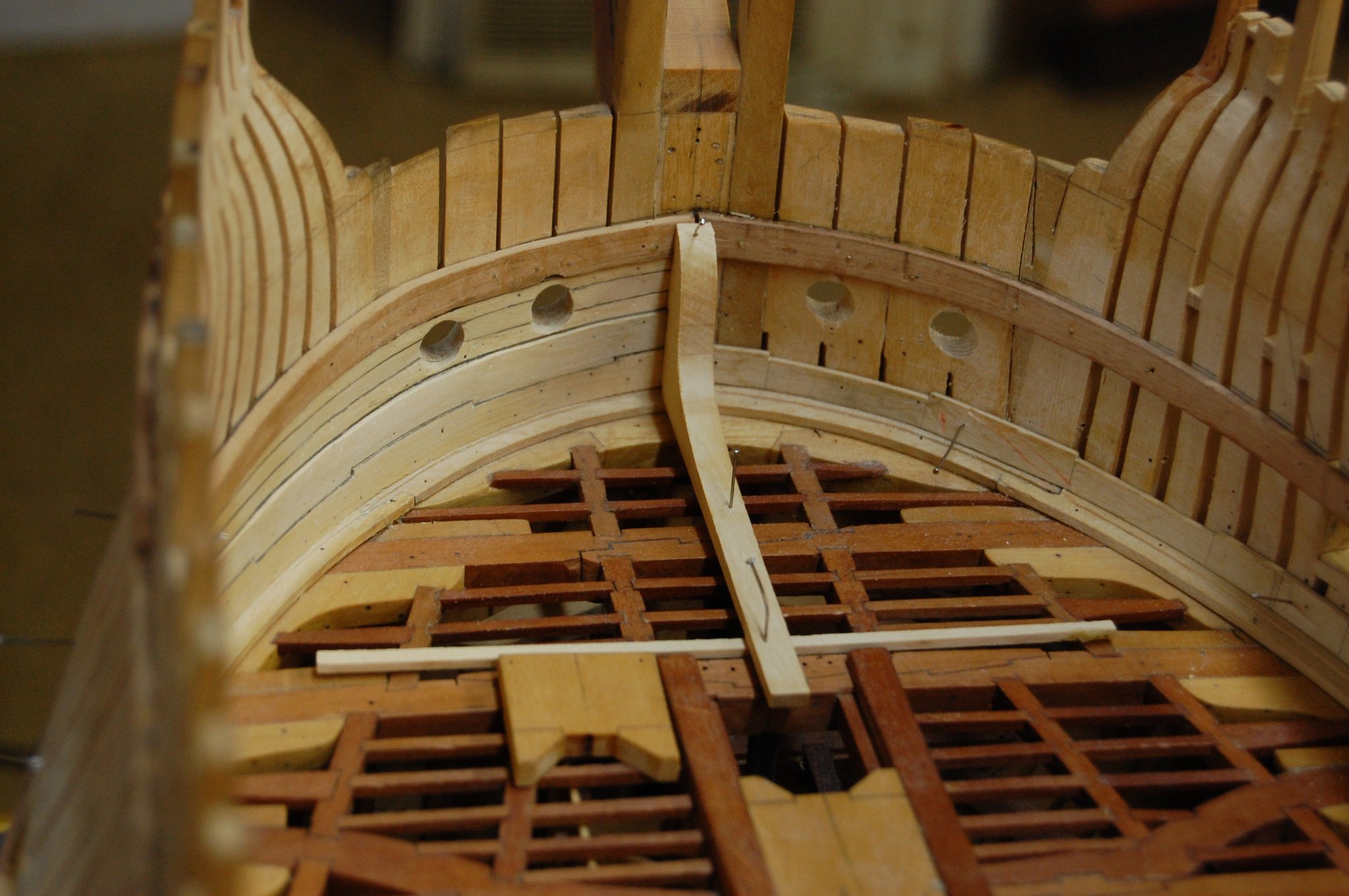
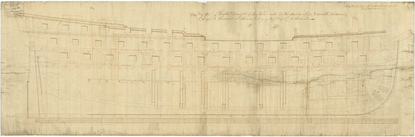
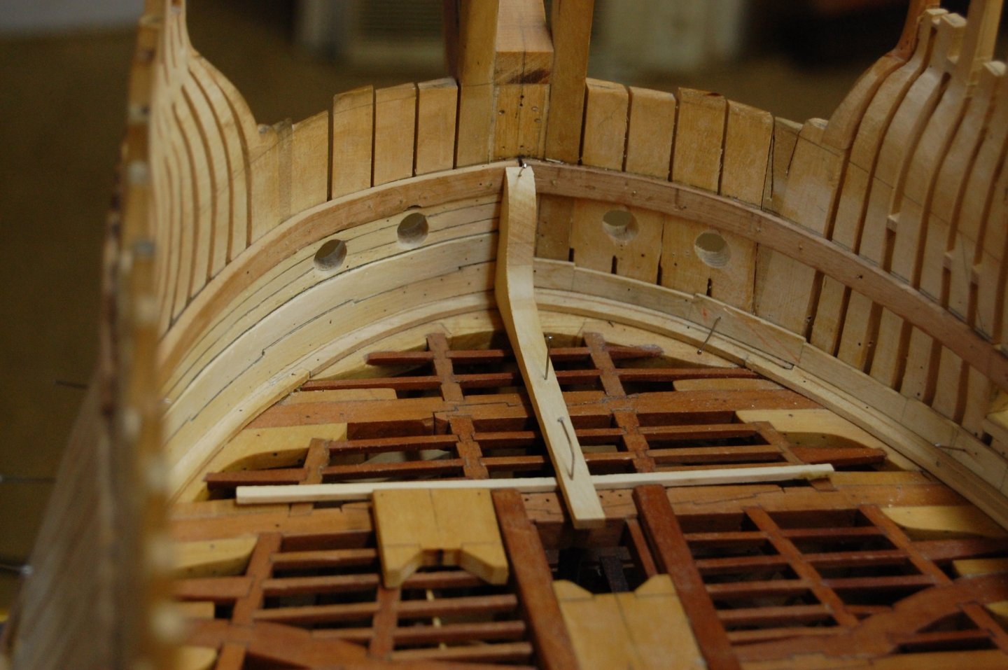
Hi Alex and Mark. Alex your right sir and it is drawn in, being a much later time frame with a few other alteration going on. Mark I wouldn't change a thing sir. When I was going through more plans, I noticed that more was of the type with the stemson going all the way up to the bottom of the upper deck breast hook and no standard, which I believe was the norm untill much later. I did see a couple , later time period that show a standard, with the stemson going all the way up to the bottom of the upper deck breast hook but when you blow them up it looks as if someone had erased the stemson from the upper deck breast hook down to the bottom of the gun deck breast hook, which tell's me you had one or the other but not both. That is untill some one comes up with some thing that says difference. Merry Christmas guys.
-
Well Mark it may not be the right time frame but, a few years later then Bellona one does show up. Merry Christmas sir.
-
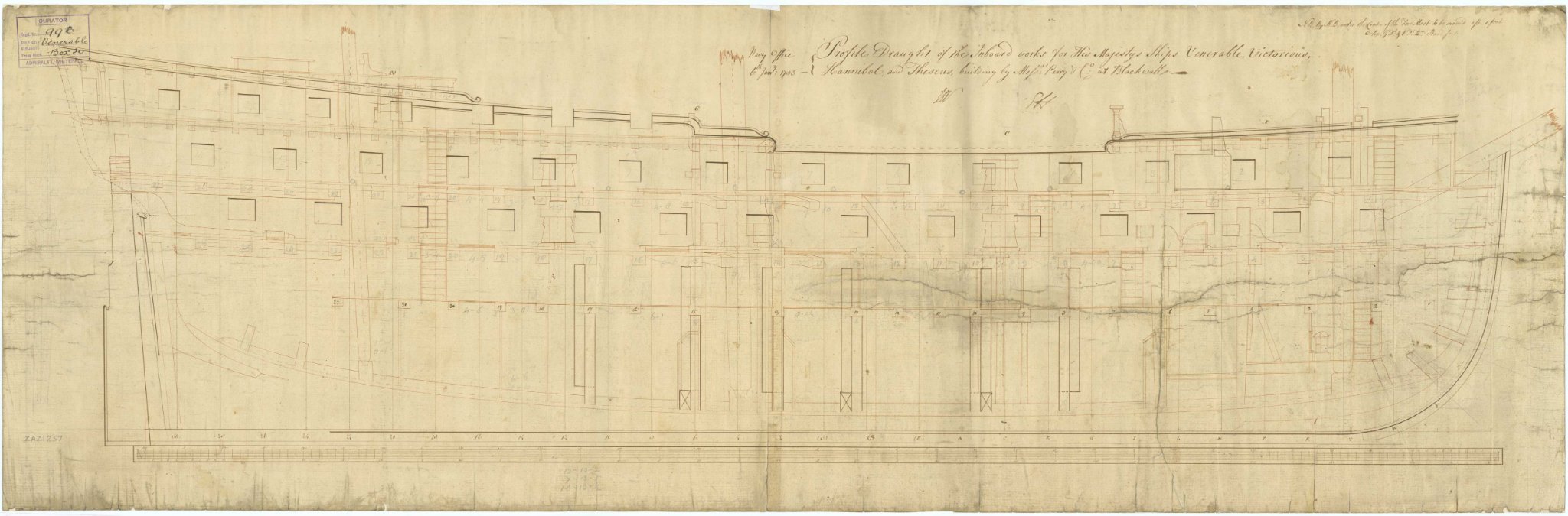
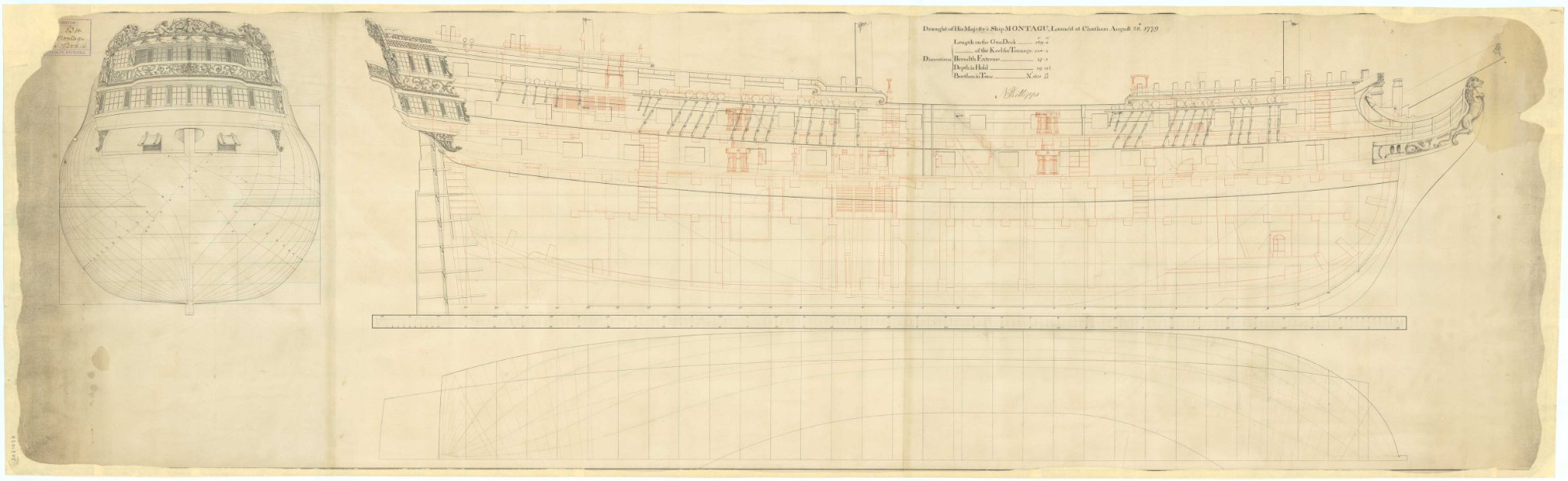
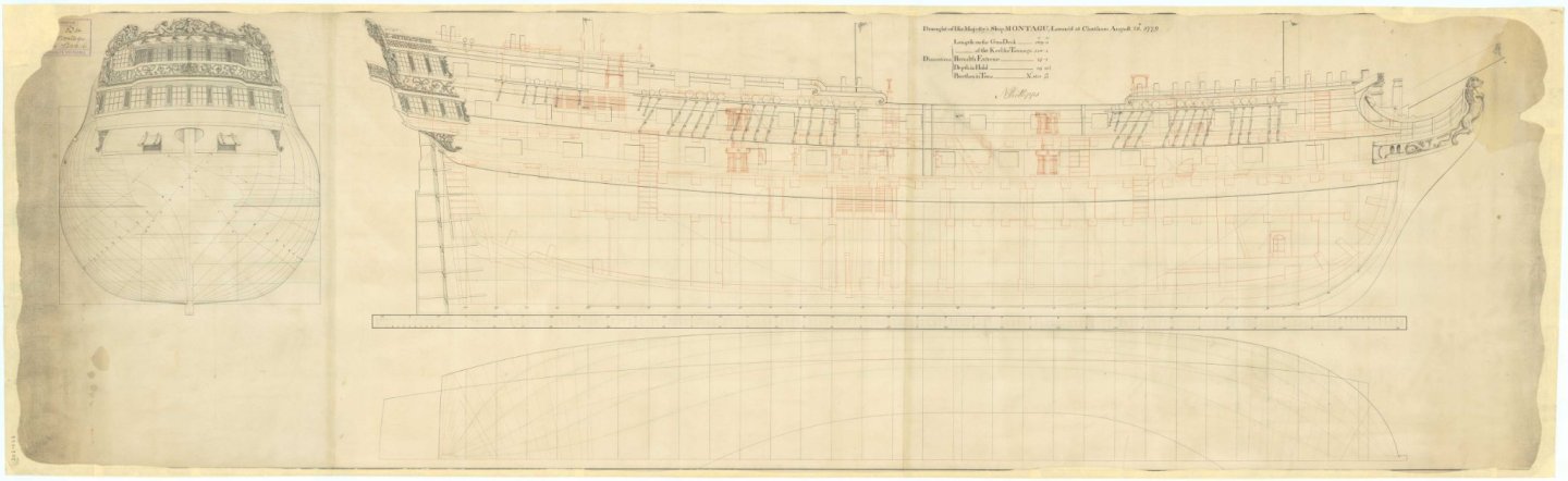
Hi Alex. Have to agree with you and went through a few plans and saw the same thing. In the contracts, found a couple that said the stemson went all the way up to the upper deck breast hook and others said it stopped at the gun deck breast hook. Some make no mention of the standard at the stemson and others do. it seems to comes down to what your plans might show and how that person may want to do it. Alan has the contract of that ship and plans that shows how this was done and his plan shows the stemson which doesn't go all the way up, which seem to be a commen thing on weither the standard was installed or not. In my cause Alfred shows the standard at the apron with the stemson stopping at the gun deck breast hook, but her sister ship the Montague shows the stemson going all the way up to the upper deck breast hook and no standard. Mark forgive me for taken up space in you log but hopfully the infor will help others. Well back to researching. Gary
-
Mark you could be right and may not of had one in Bellona time but will see what else I can come up with. Things did change through out those years and what happen in Montague time and Bellona time were different. Well Mark seems after a couple of hour's, searching seems to have turn up that looks like she may not had a standard at the stem. As you said one has to be aware of the time frame. Gary
-
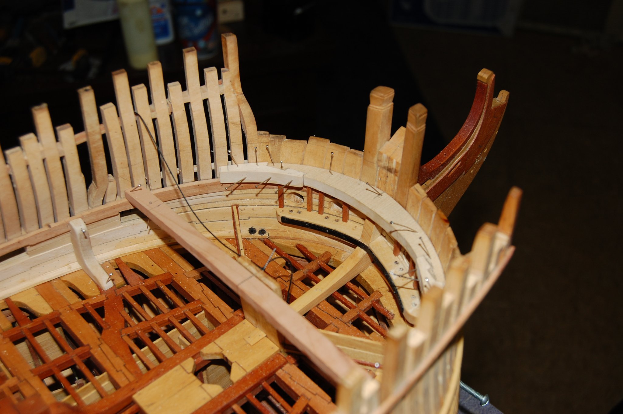
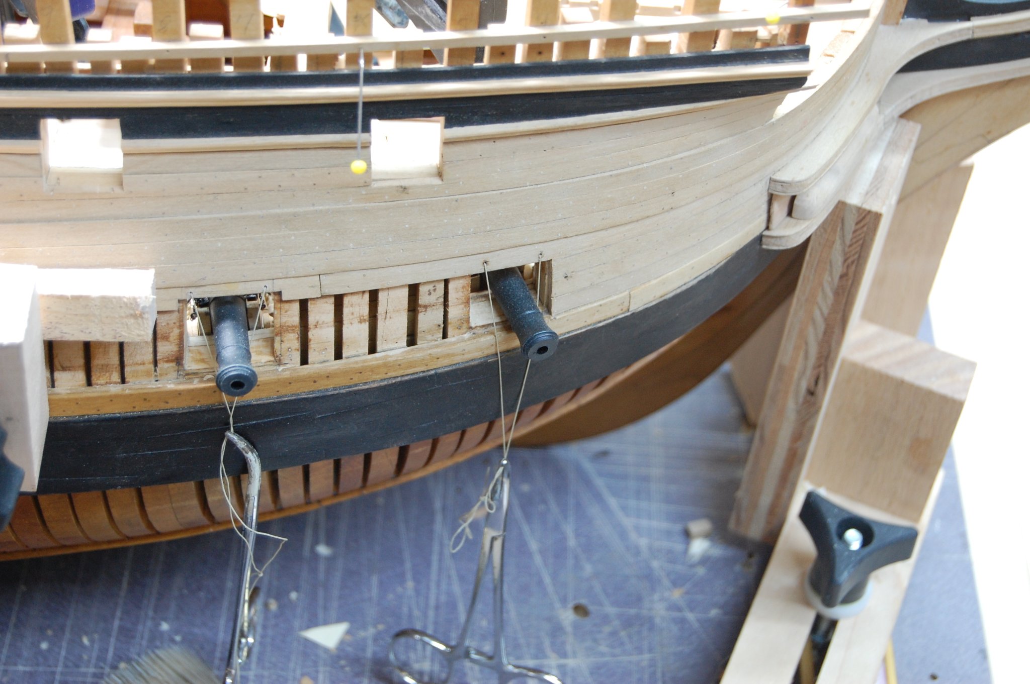
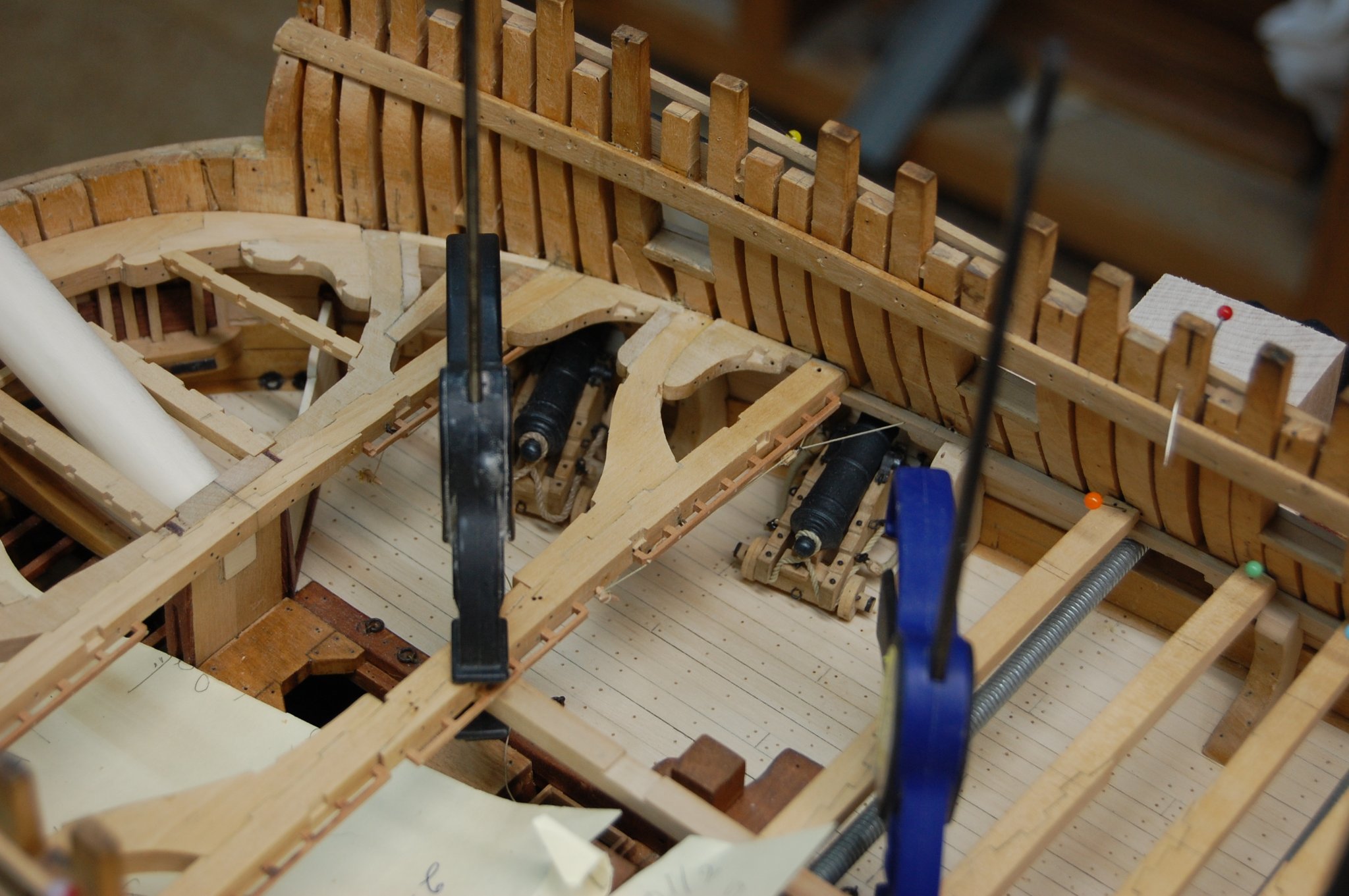
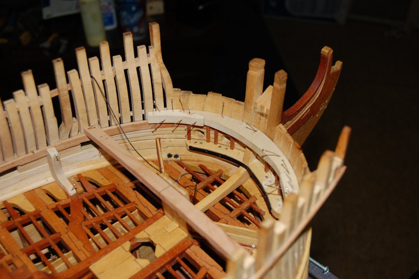
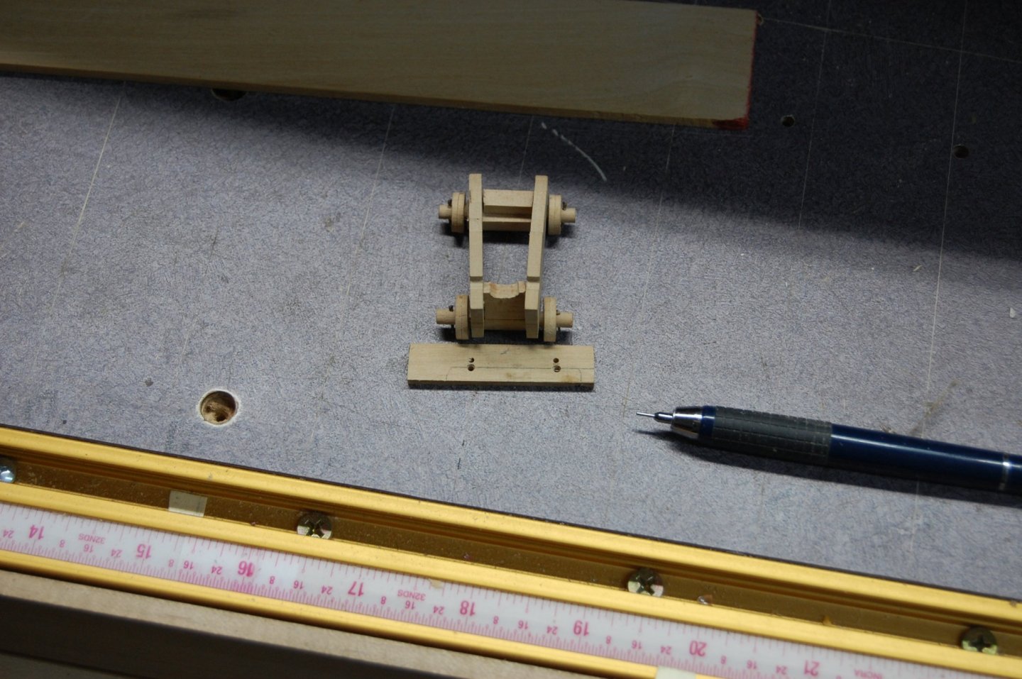
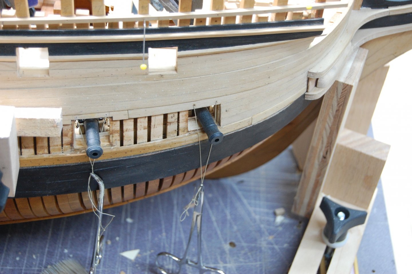
Thank you Mark. Am planning on installing the gundeck guns permanently, and then just work carefully around the barrels sticking out as I proceed. I just haven't found a better way. I did find plans that show the standard and others that had it drawn in. The plan of Alfred shows both the standard and the breast hook and another plan I found shows from above how this was put together. Am not sure what they called it but a metal strap across the front side to strengthen the standard and breast hook. Goodwin is a good source but I try to go beyond what he gives us and look for primary stuff that back's up what Goodwin is showing us. Some times I have good luck at finding what am looking for and no luck at all on other things, such as a finding the layout of the scuppers. Reading contracts is a big item for me which helps me in building MontagueI. I upload some photo's showing a little jig that help's me mount the front trucks of the gun's to the deck, by aligning up the pegs in the front trucks with the drilled holes in the deck. Like you knocking them loose is a big thing if they are not well secured. Should give you a ideal or two to help you. Am also adding the rigging for the port lid's which would be a real head ack if I waited to install them after the beams are in place.

-
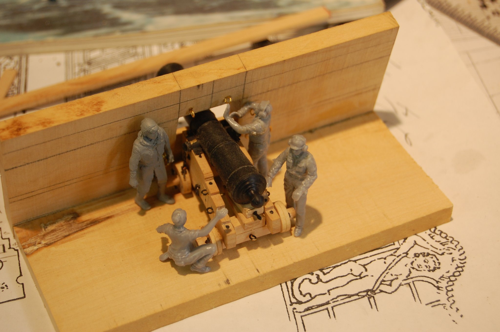
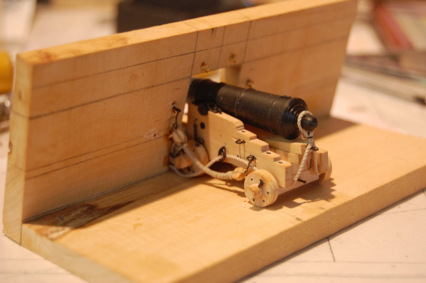
Mark I was looking at your last set of photo's and noticed some thing. Was wondering where the standand at the bow against the stem? Am sure they would have had one there. Just wondering good sir. Also you could make a gun platform to help you rig the cannons. Here is what I use to help me get the breach and tackles just right

-
Merry Christmas every one and may 2021 be a much better year for us all. Happy New year to you, and I do hope you all receive some thing nice from Santa.
-
Hi Alex. I have gone through your log at least 3 to 4 times and must say your building is as outstanding as the plans your drawing up. I am really enjoying you Anson plans and have finally answer to some question that I have long sought for a answer. Thank you again. I only have a couple of question. Do you by chance have any construction photo's of how you made the scuppers you installed and what material they were made of? If the crew here want a outstanding set of plan's for a 64 gun ship, getting Alex plan is a outstanding investment. Thanks again Alex, look forward to your next update. Gary
-
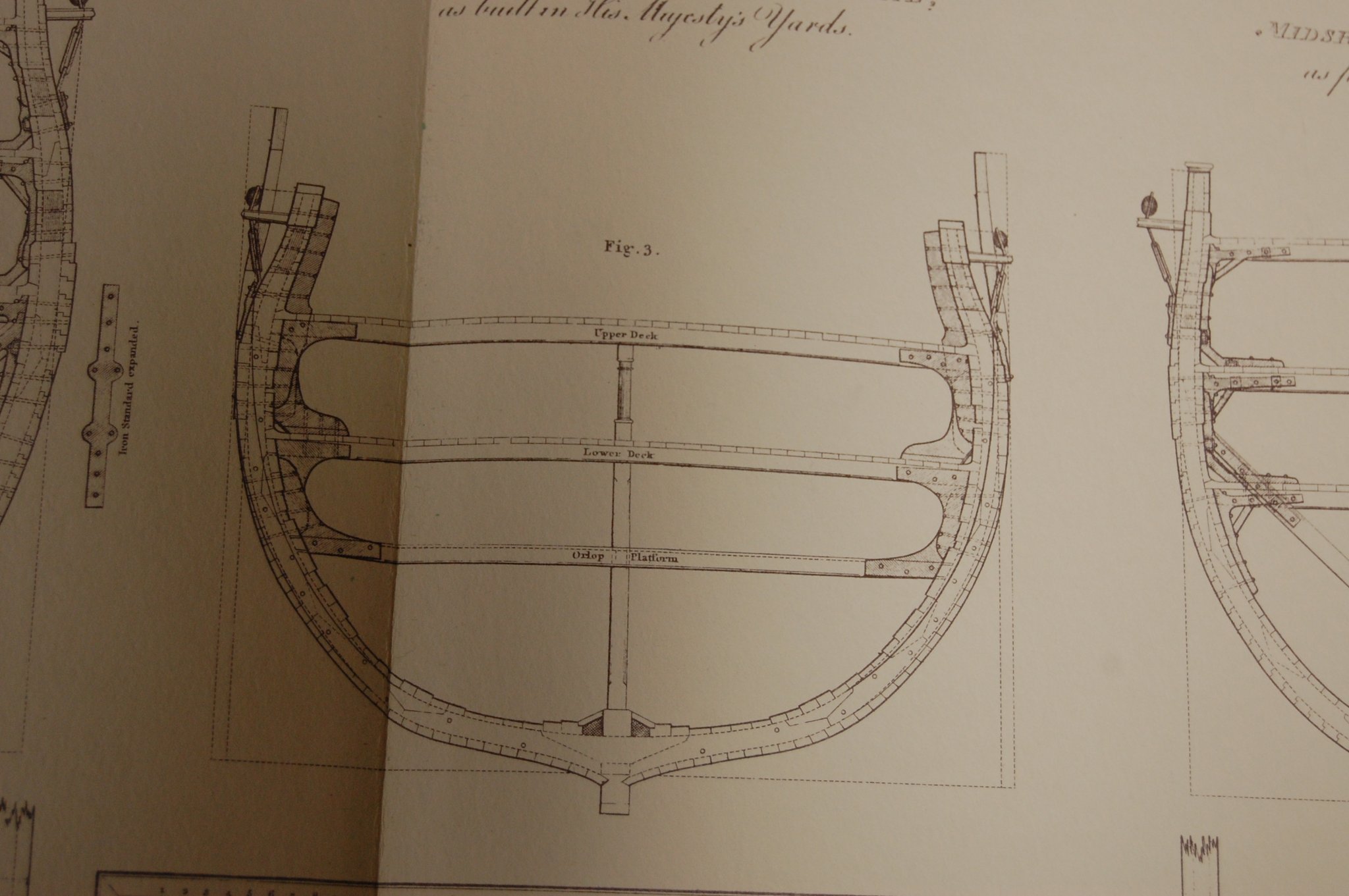
Hi Alan. If you look in Goodwin's book Sailing Man of War on page 108 he says you can see a contract in Deane's Doctrine of Naval Architecture but call's them shoulders of two inch plank under them. This is a contract that was written for a 3rd rate of 1666-7 and is on page117 Am not sure when the name was changed from shoulder to sholes. I did find this in M Stalkartt Naval Architecture 1787 page 228 and says Sholes, Pieces of plank put under the shores where there are no groundways. Now when you get to 1805 in Steel books, such as Steel the Shipwright's vade-mecum 1805, page 151 he say's sholes, Pieces of oak or plank, placed under the soles of the standards, or under the heels of the shores, in docks or slips where there are no groundways, to enable them to sustain the weight required without sinking. Old hanging port lids are particularly suitable and useful for this purpose. He also gives the meaning for Sole page 152. A sort of lining to prevent wearing or tearing away the main part to which it may be attached; as the rudder, bilgeways. I also included a photo of the standard's showing the sholes attached on the lower deck Plate 8 from Steel's Naval Architecture. Also Mark if you read this, believe this is the plate that I used that shows the opening between the standard and the water way. I did look for this in the contract's but didn't find any thing in them. Well guess what guys the moment I said that, I found it in one of the contracts I have. My apology. Gary
-
Hi Mark. No sir I didn't pin them and when I get around to the upper deck I probably will pin them in place. The bolts were made from Amnesia by Sunset, a fishing line black in color and Ed used it in The Naiad Frigate. When I was laying out the holes I just eyed that part to get as close to even looking when you look at them.
-
Hi Alan. Am not sure and have not come across any thing that talks about rot, It would have helped with standing water and help preserve the bottom of the standard but I believe that Fincham points more to the strength of the joint. He says , the standards were of wood or iron , and in general bolted with nine bolts, four up and down, and five in and out, the up and down bolts were collar beaded, and driven from the upper part of the standard, and clenched upon the under side of the beam. In general, the toe bolt, when the standard was of wood, was driven through a plate that clasped it, as in the working of the top side there was a great tendency for the toe to separate from the deck, and frequently to split. The in and out bolts were driven from the outside, and clenched upon the standard. This come from the reprint Fincham's Ship Building by The ship Model society of Rhode Island 1933.
-
Hi Mark. the sholes goes on to the bottom of the standard. Here is what Fincham said. There were in general from nine to twelve standard on each side, fixed on pieces upon the deck, called a shole, from three to four inches in thickness. It was like the standard sat on the shole and then they sat down on the deck. They was just a plank that was 3 to 4 inch's thick that was attach to the bottom of the standard, length wise depended on the length of the bottom of the standard it self