DONATION DRIVE - SUPPORT MSW - DO YOUR PART TO KEEP THIS GREAT FORUM GOING!
×


garyshipwright
-
Posts
930 -
Joined
-
Last visited
Content Type
Profiles
Forums
Gallery
Events
Everything posted by garyshipwright
-
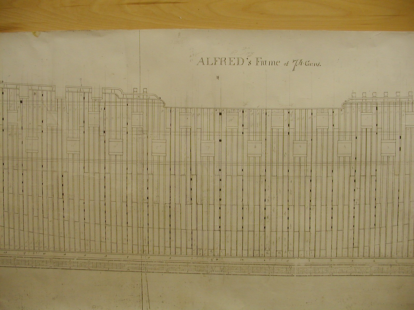
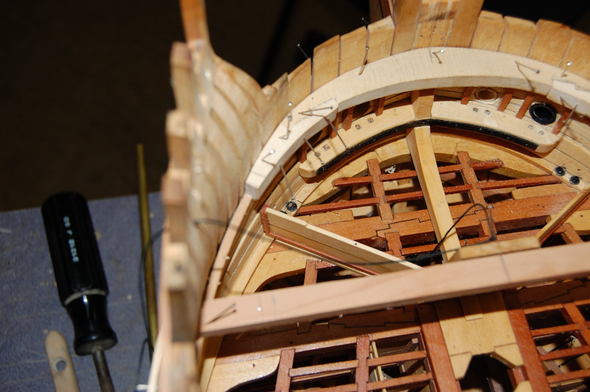
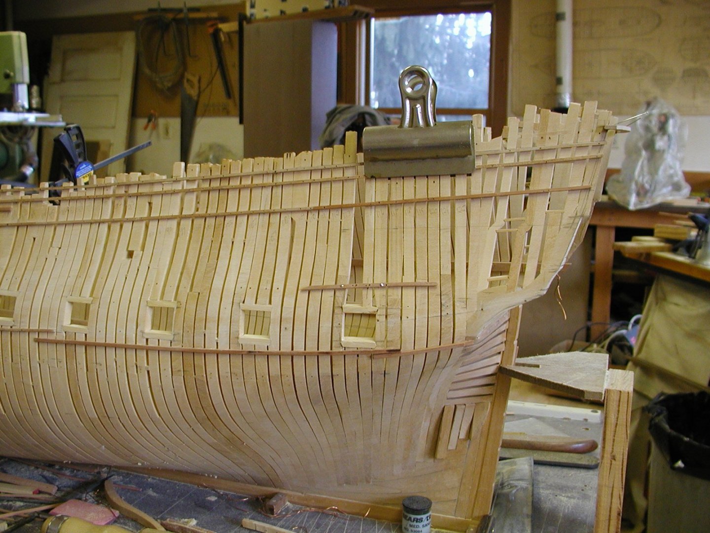
 Hi Clay. Well good sir my thought process on the framing was I used butt's to hold the parts of the frame together that is shown on page 18 in Goodwin's book. Being a expert , thank you for that, but call my self more of a student who will never finish school. When i started building my frames I did use chocks to hold the parts together but being that you make about a 130 frames it takes awhile which is why I used the butt and dowel that hold's those parts together. Not as time consuming and once the planks are installed on the outside and inside you can't see the chocks but if I had to do it again I would have installed the chocks, but today that is just a bit of hind sight on my part. Installing the chocks does take a while and after three years of framing figure chocks would have added 2 years to their building, for me anyway. Chock's would be more accurate doing our time frame. Now the sister frames would have been called bends and it seems that He shows this on page 14,16 and 18. What they usually did, as far as I can tell in Alfred's/Warrior time frame, would be to to build one bend( two frames put together as one) two single filling frames that did not touch each other and then another bend. Some where around the dead flat there was a changing of the floors so at that place you would have a floor, a first futtock and then another floor. What they did is at the forward part of the hull the floors would be on forward side and aft the would be on the aft side. I added a photo of Alfred's framing plan and my framing , they are about as close as I can get them. If you look at station 1 and the dead flat you will see the switching of the floor. How you can tell is that there is three filling frames between the two bend's and usually you only had two filler's. Now the bend's didn't touch as the went up but was pushed apart with blocks of wood , so the upper parts of the frame's could make up the side of the gun port. Those parts of the frame were bolted together were the blocks were installed . I colored those blocks black and shows that this was a station and the filling frames did not have those blocks. Hope this makes sense Clay. Gary
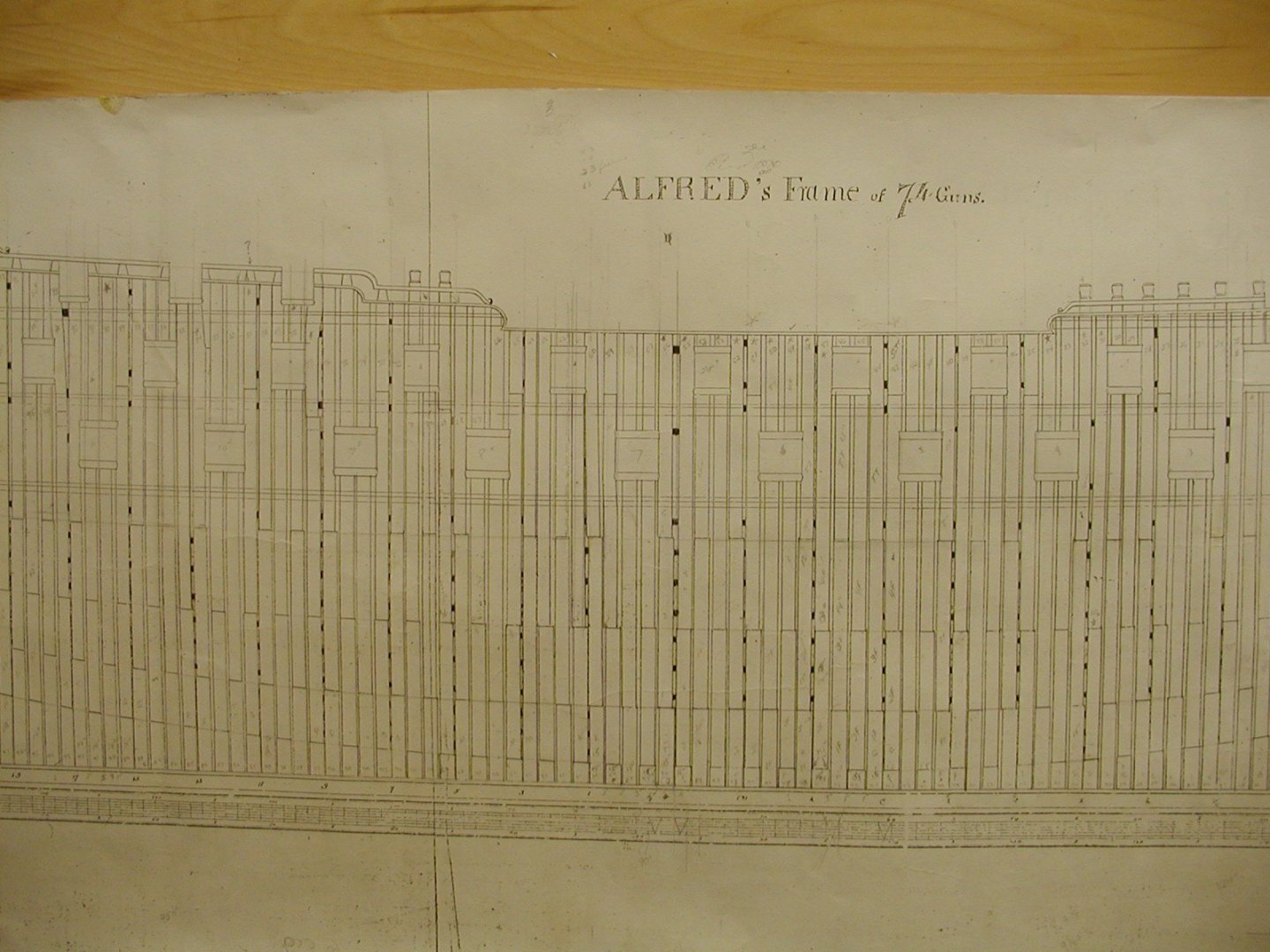

- 835 replies
-
- 15
-

-
Thank you Marsalv. The machines that we use will always be controversial but then again as you said, they will be just another evolutionary step, sort of like when I purchased a mill for my self. As far as what tool's you use, be that a set of carving tools or Cnc doesn't matter, both takes a lot of work and skill to achieve what you have shown us. One last question Marsalv, but what tool bits did you use when you did you cnc carvings, a self made set or a set that one can purchase to do the carving's? I am getting in to CNC, something that I should of done years ago and knowing what the right set of tool bit's that one needs for miniature carving in cnc will really help. I have been looking but so far have come up empty finding a set. Look forward in hearing from you. Keep up the outstanding building your doing and thank you. Have you ever thought about doing a a tutorial on Miniature cavings in cnc? Just might be what some of us need to help us grow. Gary
- 589 replies
-
- 5
-
-
- le gros ventre
- cargo
- (and 1 more)
-
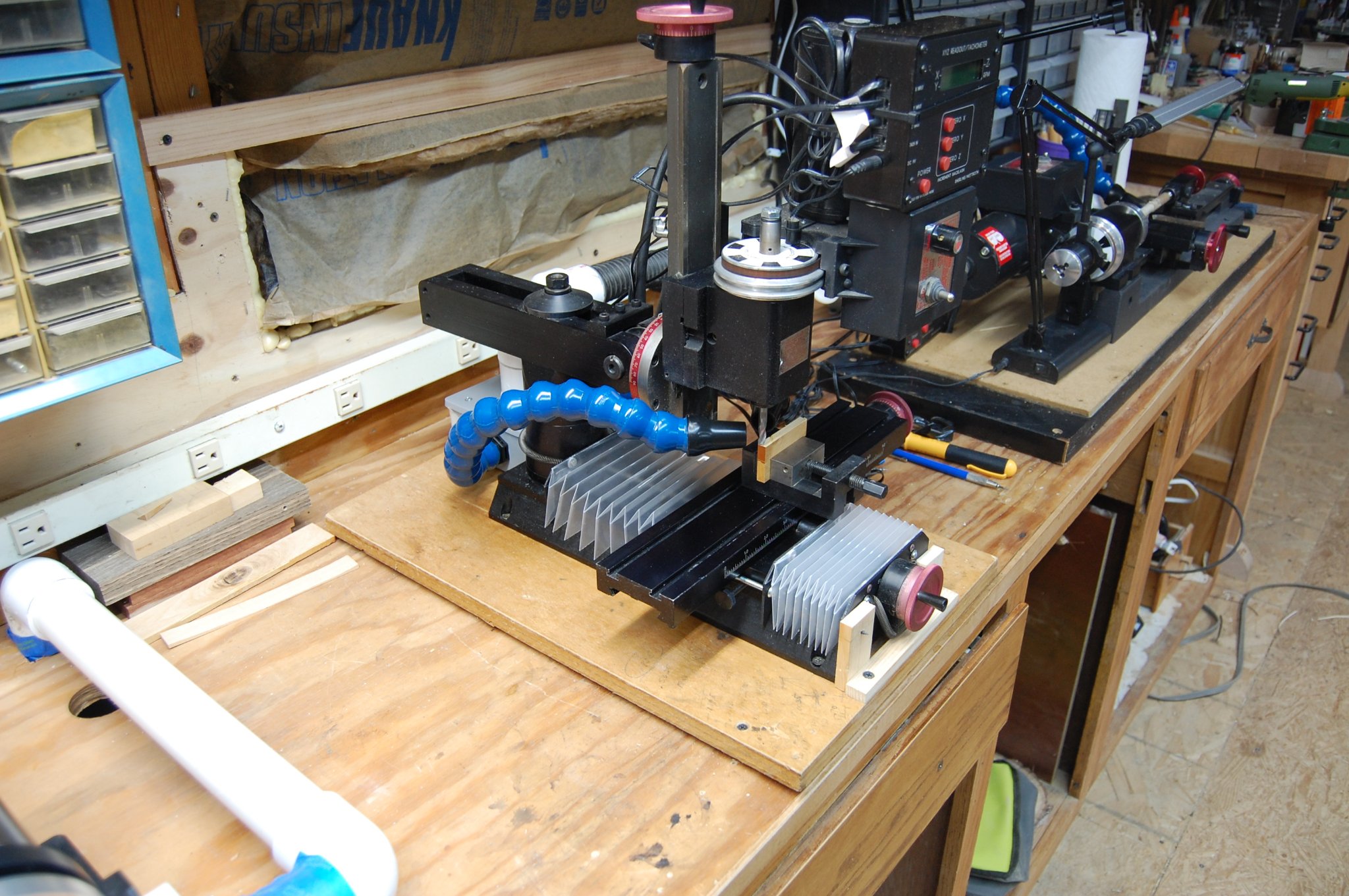
Well guys the Cnc parts are on the way for fitting out the mill and lathe and maybe I have it all put together by the end of the month. Learning how to use the programs, well that just may take a little longer. Will add more later. Gary
-
Hi Marsalv. Have a question for you. What program are you using for doing your carvings? I just may purchase the same one. At the moment am looking at V Carving which might be the route for me to go. Thank you and keep up the outstanding work. Gary
- 589 replies
-
- 5
-
-
- le gros ventre
- cargo
- (and 1 more)
-
Thanks druxey and you may be right. I did take a look in Boudriot 74 gun ship vol 4, page 74 and it shows the exact same set up that I believe was common for are era. Seems that the messenger just went around the front of the bow sprint and was just helped along with the crew with no rollers in the manger. Apparently both the French and English were using the same set up during our time frame. He did say that they had pillars/rollers placed out far enough from the center line to keep the messenger from rubbing up against the pumps and other items. Did the English use rollers along the side, maybe, maybe not, can't find any thing until1792. Probably won't really ever know but when I finally get to installing the pillars I just may get a answer for myself.
-
Hi Clay I went and looked in Peter Goodwin's book, The Construction and fitting of the Sailing Man of War 1650-1850 And talks about the Messenger Rollers, on page 156 and says that they didn't come it to use until1792. He says that maybe a simple snatch block may have been used before this date. Am think out loud now, that maybe they used two snatch block one on each side to help the Messenger cable around the curve but that's just my thought's on them. Am not sure if you have Peter's book, but would be a good addition for ones library. The one I have is probably about 30 years old and is showing just a bit of wear and tear.
-
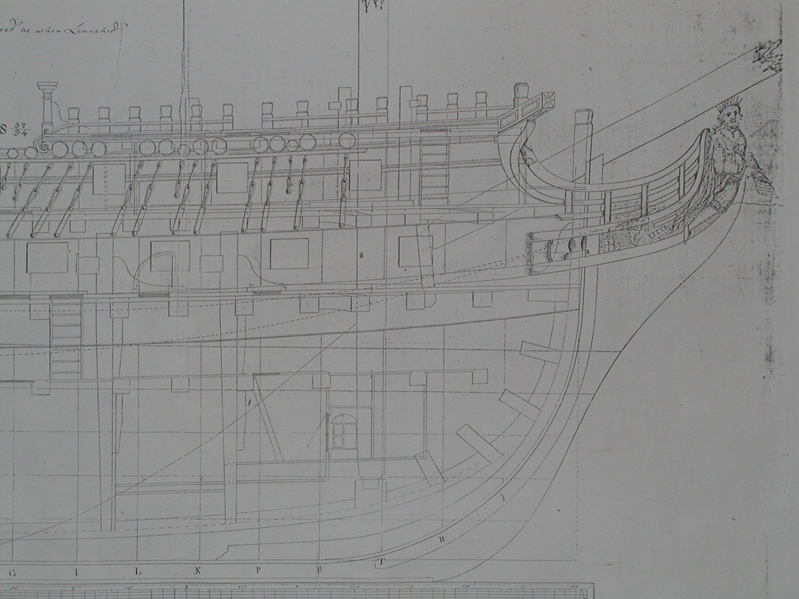
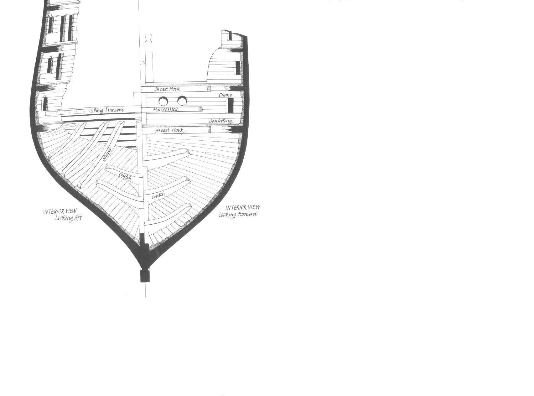
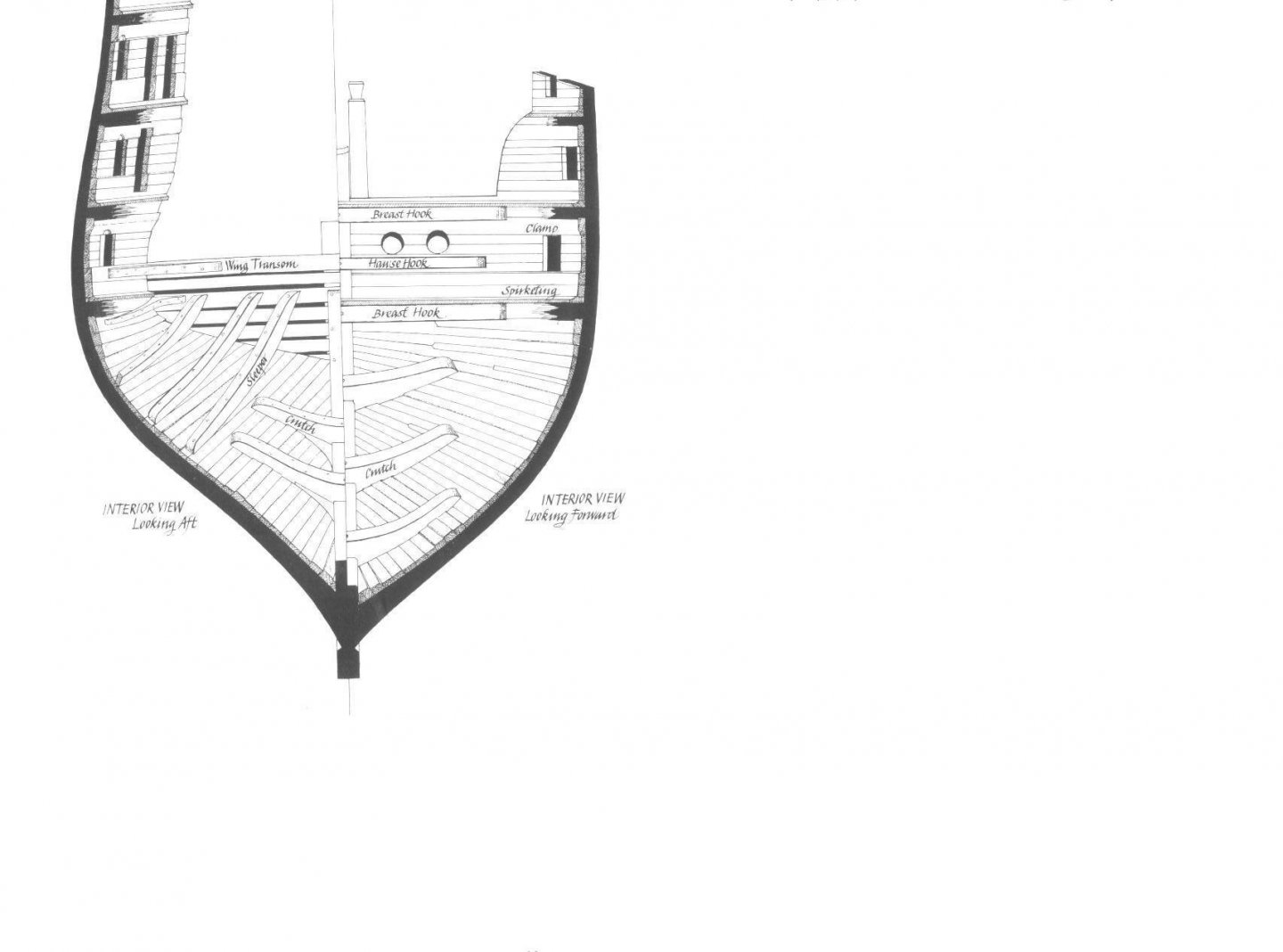
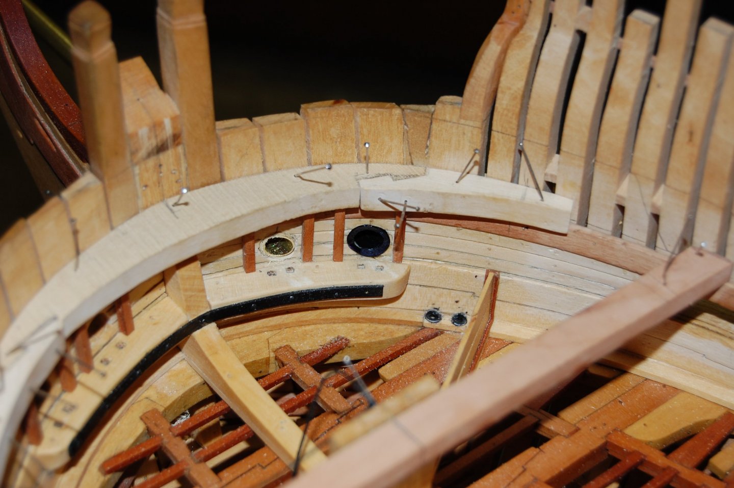
Hi Mark. Your set up looks very very good and may have to redo the set up for the other tools like the disk sander and thickness sander. My Byrnes Prec saw are on a roll around tool stand that has a vacuum in side of it. I did buy a couple of blast gates for the mill and lathe but didn't install them. I have one of those on-off- switch and may get another one for those tools. The one I have is on the full size drill press and the vacuum. I do have a switch above the bench that turns on the vacuum but having the hose loose I can use it to help keep the bench clean when the machines are not using it. Hi Clay. In your first photo it shows that stanchen but I have not come across one in our ships manger time frame. As far as which hole they used, I don't think it matter's and was left up to the person in charge and you being the person in charge is left up to you. Now I saw that photo from Romero and there is a couple of things that stick out like a sore thumb and both do not fit our time frame for Warror or Alfred. The rollers that he shows didn't come in to use till the 1800 I believe. I take a look and see if I can find where I read this. I looked for them but could never find any thing about them, till our ships time which is probably why Hahn left them out. The only answer I can give about the messenger going around the foremast in the manger was they crew helped it. Now on the other hand, they may of done something like the rollers in Alfred/Warror time frame but nothing I can find. If you find a answer good sir would very much enjoy the answer. I believe he didn't give a source was because he was the source and probably used McGowan's drawing of the Victory which does show them but once again they would be out of place in ours. Another set of items that you see in Romero drawing is a set of standards that look like knees up against the wall, which there should only be one and that one would be in the center up against the stem. Another item that is missing is the Hawse hook that set below the hawse holes. This would be on the Alfred/Warrior but not on the Montague. I will put a photo or two, one of Alfred and one of Montague and you will see the difference. If Romero had looked in to a couple of contracts during that time he would of found that they only had one at the bow helping strengthing the stem. He could of used Steel of 1805 could also have came in handy to help him. O well live and learn.

-
Hi Clay. That's ok, and as far as high jacking the thread, to me it just a exchange of infor and really like hearing about other folk's workshop and places of where they do their hobby's. Most of they ideals of the shop came from other good folks that just like sharing there shop's much like your self. Since you mention the basement and the dust, what about hooking up a dust collection on the outside that would help get rid of the dust. My collector is on the inside of the shop but is vented to the outside. I could of hooked up a set of filter's but after awhile they would get dirty cutting down on the amount of air that would be pass-through to the outside. Beside those filter's are very costly and just went with venting outside. Do believe it help's keep the dust down. You could also maybe add a Hanging air filter system which would help with the dust. Just a couple of ideal's and the cats, well I leave that one up to you. As far as the noise goes, if its inside you could always put it in a sound proof box. Mine is in the back room which really cuts down on a lot of the noise that comes from it. Gary
-
Thanks druxey Being that the shop isn't air tight it should have adequate ventilation. Another thing about the heater is the intake and exhaust. The intake for the fresh air comes in to the heater on the outside pipe, which wraps around the inside pipe which is the exaust which also keeps the exaust pipe cool while getting rid of the CO. Sterling GG Concentric Vent Kit Add Separated Combustion to the GG with the Optional Concentric Vent Kit http://www.littlegreenhouse.com/accessory/h-ster-con-vent.jpgSterling GG heaters can be converted to separated combustion when this kit is added to the heater. Separated combustion heaters draw combustion air from outside to ensure that the unit will always have plenty of fresh clean air. The fresh air supply reduces common concerns about dusty, dirty, or high humidity applications. You can also decrease heating costs by as much as 10% because no cold outside air is being sucked into the structure when the heater is running. What does the concentric vent kit do? The concentric vent kit allows the air intake and exhaust to vent to the outside wall with only one hole as shown in the picture below. Use for horizontal or vertical vent

-
Hi Clay. Not having a warm place in the winter time would suck sir and would drive me crazy. Just a question but what if you blocked /walled off just a spot for the hobby, is that a possible? Am sure you have already thought about what you can do about your shop. I probably spent about 2 to 3 grand over a time span of 5 years getting just the right gas heater and parts and piece which I installed in the shop last year. I had a electrical heater but it was costing to much to run and before that I tried a propane set up and that didn't work out either. Some were I read about the different type of set up to heat one's shop and probably have gone through all of them. The gas one is the best and has really brought down the cost. Wish I had gone gas a long time ago. In the summer time I have a window air condition but only run it when the heat goes way up. Hope your heating problem get's fixed so you can spend more time working on your ships and hobbies. Gary
-
Hi Clay. You can get the flare shape nozzle from loc line which is 3/4 inch but the also make some nozzles in the 2.5 inch size. Go to Modularhose.com and you can take a look there for what you need. The 3/4 inch flare nozzle come in a set of 2 for about 9 dollars plus shipping. Once you get yours set up would be happy to see how your's comes out. Gary
-
Thanks Mark, it should pay for itself since it should keep down the dust and a lot less time on the clean up. It won't get it all, but we will see. At least thats the plan . Gary
-
Thanks Mark. Yes the funnel is part of the loc line system. They come in a pack of two for about 9 dollars. Not bad if they keep down the dust problem.
-
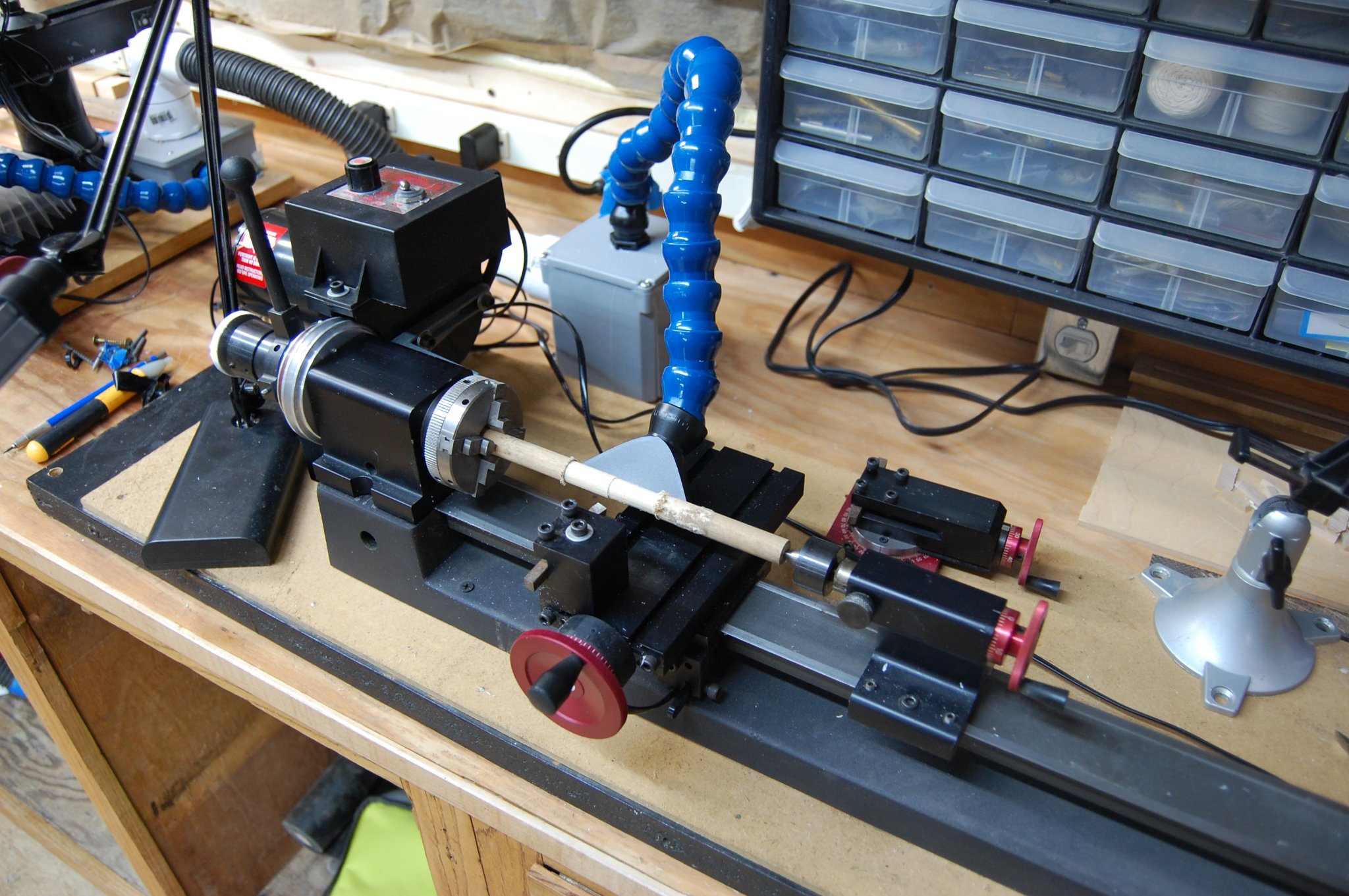
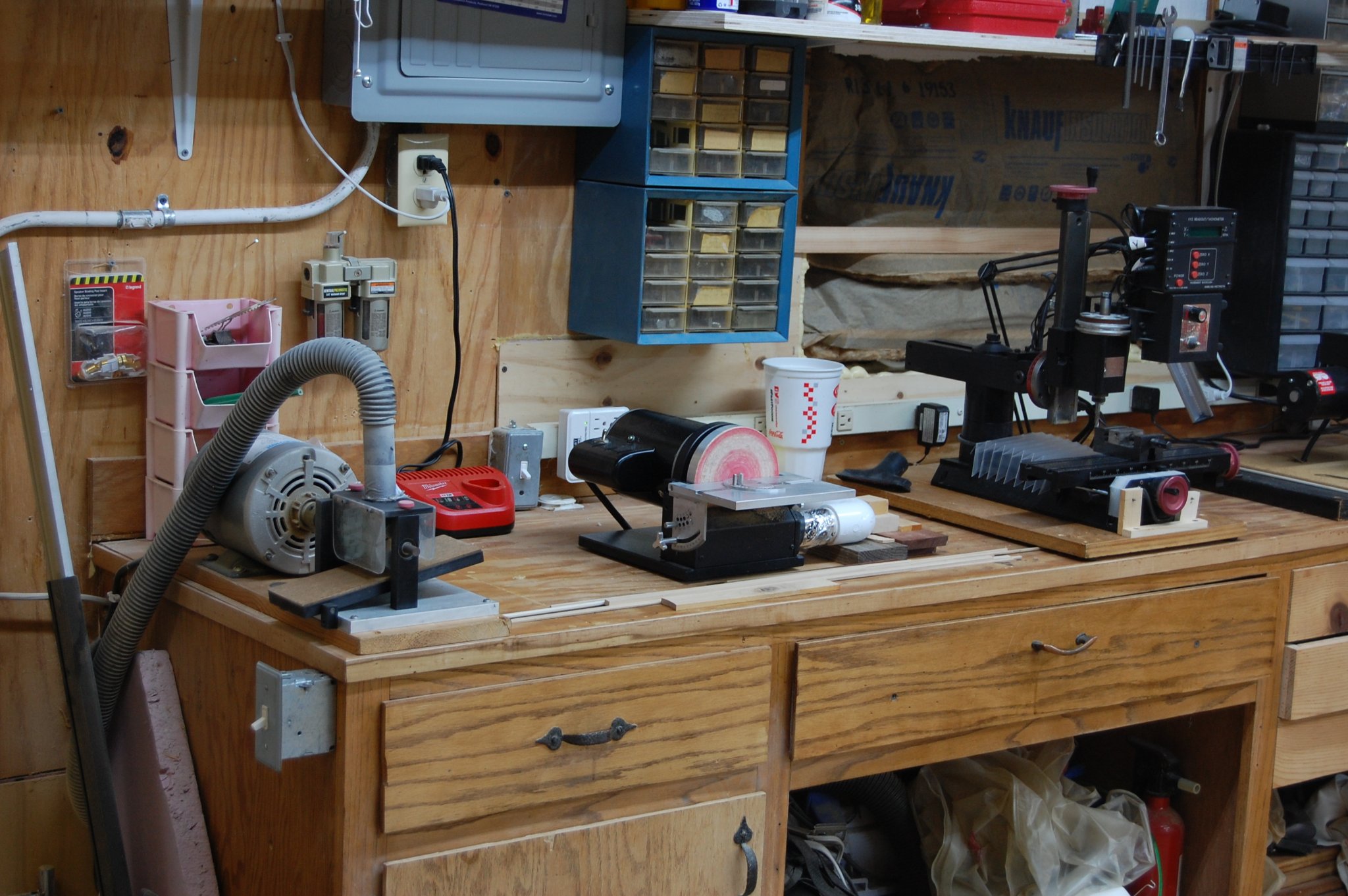
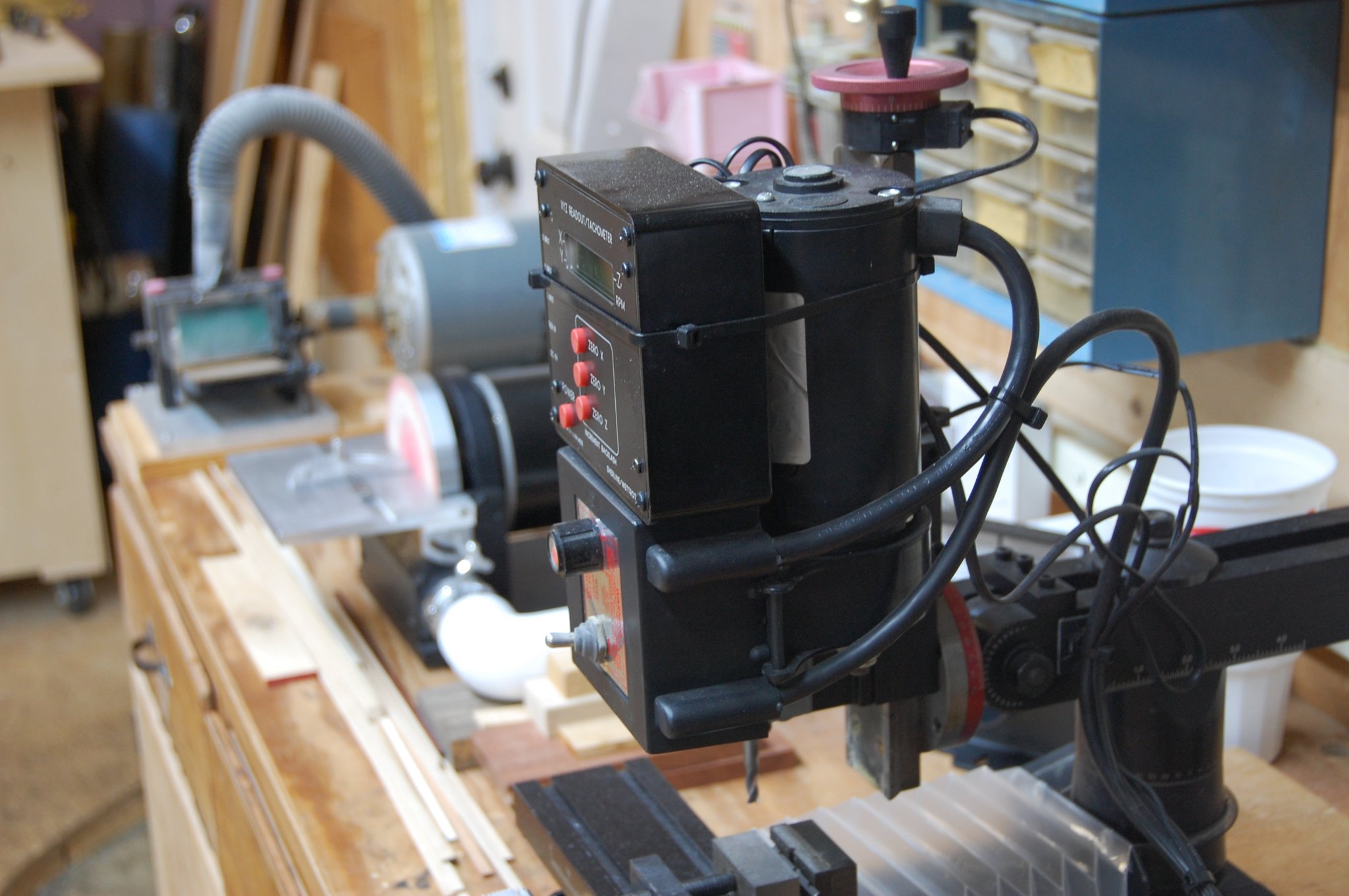
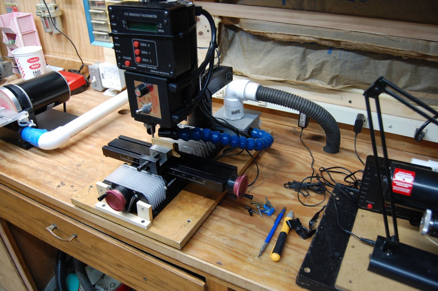
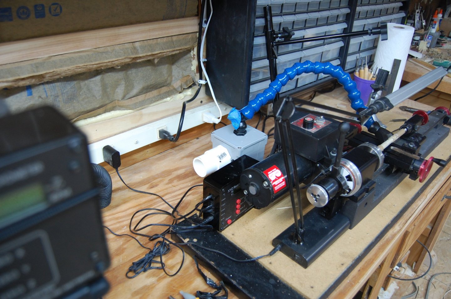
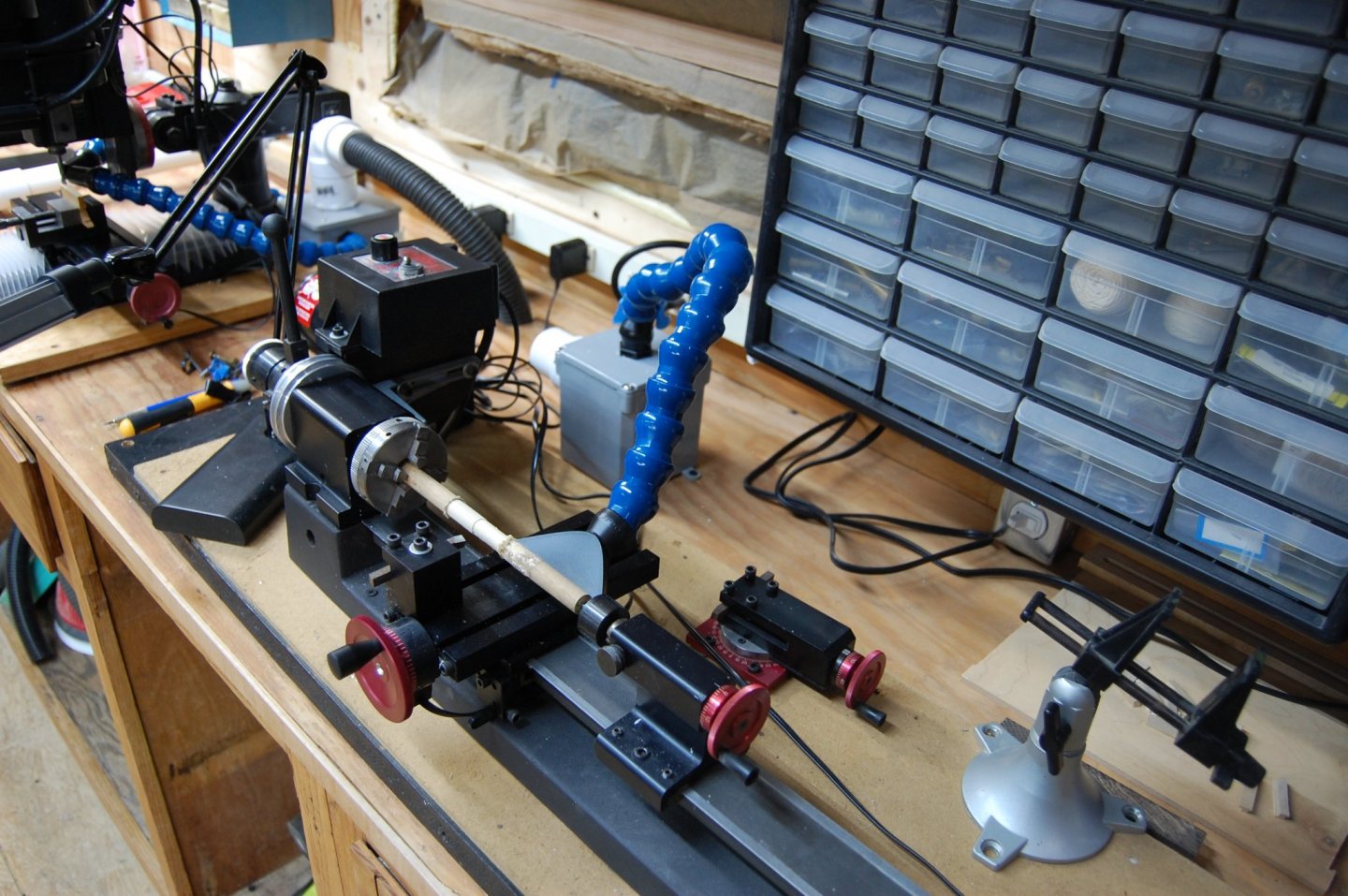
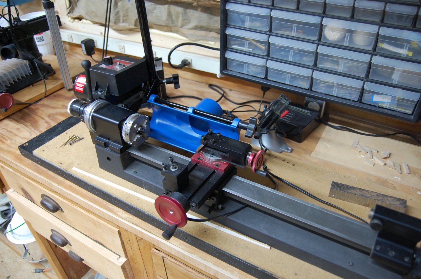
Hi Mark and Mark. Thanks for bearing with me and I finally finshed the dust collection for the lathe and the mill. For the last couple of days I have been fine turning the dust pick up. The key to making this work is the Loc line tubing that you can buy. I purchased the 3/4 tubing with a couple of loc line fittings, along with some pvc boxes, a few fitting of Pvc as you can see in the photos. The nice thing about the loc line its small, stays in place, and suck's up the dust right at the source. The only item that has to be moved from the mill to the lathe is the hose from the vacuum which is located under the work bench. Every thing is fixed but the hose and with a switch on top of the work bench back against the wall the vacuum cleaner comes on. Well within reach of the machines. I like being able to turn on the tool and vacuum at the same time but in this case the switch on the work bench works fine and may one day work on the tool turning on the vacuum cleaner. The other nice thing about the vacuum being underneith the work bench I can put in some in some sound material to tone down the sound. Anyway here is some photo's of the set up. I may also in the future change the moving of the hose to a couple of pieces of Pvc from box to box, with the hose coming up in the middle of a tee. Hope this is of help to those of us that hate dust and cleaning up.


-
She is outstanding and the attention to detail is also outstanding good sir, and you have my highest respect for your metal work and boat building skill's. Thank you for sharing. Gary
-
Hi Mark and Mark. I have a couple of ideals am working on and waiting for some parts to come in the next week and once I put it together will add some photo's here and it may just give you some ideals for doing your's. Gary
-
Hi Mark and thank you for a reply. What I was thinking was more of a permanent like what I have hooked up to the disk sander and thickness sander. Nice about this set up is when I turn them on the vac also comes on and is stored under the work bench, out of the way. Any way thank you sir. Gary

-
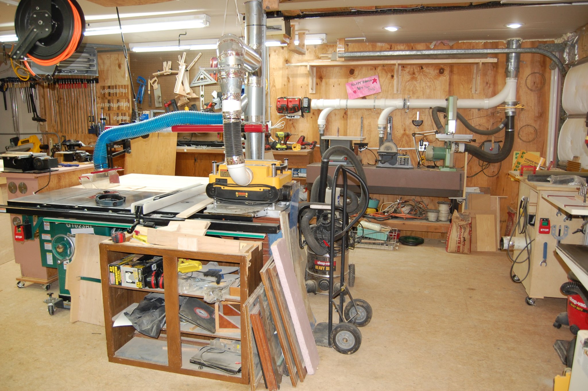
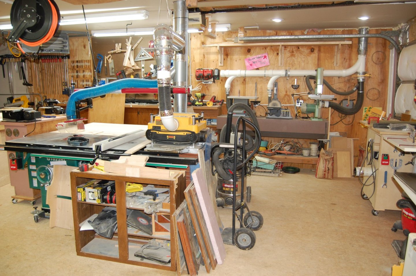
Hi Hakan and you may sir. I have a 10 inch bandsaw and two small table saw's a Byrnes and a Preac saw and would be lost with out them. The band saw is a Inca that is probably 20 years old give or take 5 year's that I use to rip stock down to a size that can then be used on the mini table saws. If you look to the left of the main table say you will see the Byrnes and Preac saw and on the right side you can see the green band saw. Hope that answer your question sir. Gary
- 835 replies
-
- 11
-
-
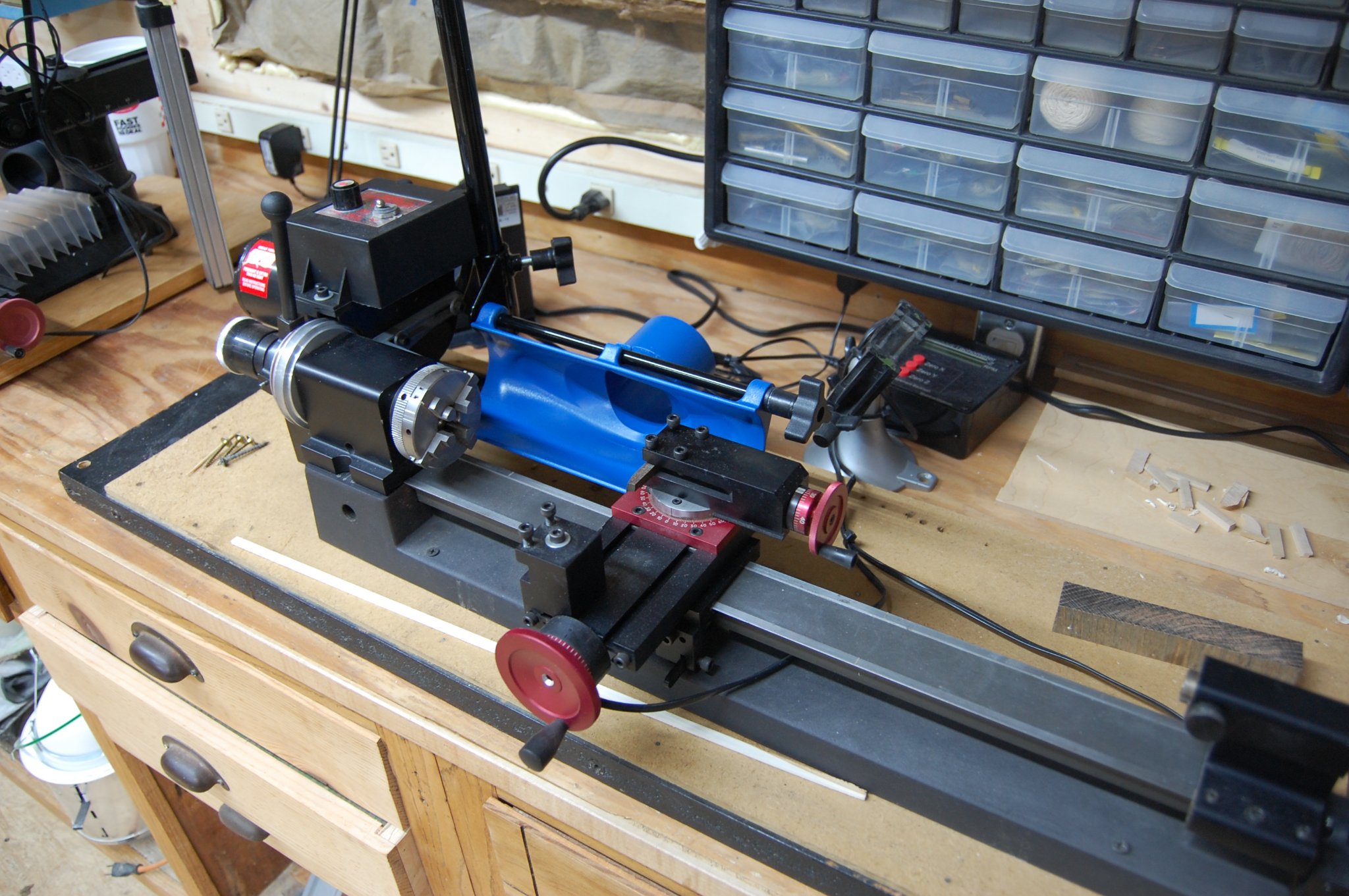
Hi Mark i just used a cable tie or two and just strapped it to the motor. Vibration and heat from the motor doesn't get hot enough to affect the DRO. Question, do you have dust collection hooked up to your lathe or mill? am looking for ideal's to hook up some thing and maybe some one can point me to where I can see some ones hook up. I purchased a dust set up for my lathe from Rockler and am working on a set up for both the lathe and mill as we speak but nothing set in stone at the moment.

-
Hi Harvey. Am not sure but it may be the 1/72 space shuttle with booster's by Mongram or the Tamiya 1/12 scale Formula 1 MP 4 6 Honda made made i believe in 1991. It seems a little on the hard side to figure out when the kit was made but will take a second look. Gary
-
Nicely done Alex and agree with druxey completely. Gary
-
Hi Guys and am sorry on the slow response. Christian I really like WNW kits and was sadden when they went out of business. Now it seems the only place to get one is on Ebay and they are asking for almost three times the amount. I did get the Meng kit of the Red Baron plane the Fokker which I do believe comes from WNW. A good kit with lots of detail. Druxey that dust collector has been a life saver helping cut down on the dust in the shop and since all of the wood is cut in the main part of the shop should help's me keep it out of the back room were I have a few books such the swan books. In fact I have the original monogram that was sent out to the members in chapter's. . Only thing missing from them is a autograph. Hum I wonder. Thanks Mark I still work on plastic models and as you say it still takes me a couple of months to build on. Problem with me is I try to add after market parts to just adds on to the build time. Hi Clay. Your very welcome sir and all you have to do is just ask. Hi Martocticvs and thank you, she is getting there.
-
🙃🙃 What, what holes. Dang it, I was hoping no one noticed. Ok back to building.
-
Some Mark just call it giving a really good friend a hard time and one that has a very good sense of humor but you way of thinking sounds better. Most of the time I have that same condition called complexititus. Now please don't ask me to say that word, did good just typing it out. Gary
-
Shoot druxey mine was a model T. I drill a hole the size of the trunnion, cut the piece of wood in half at the hole and then taking that same bit, pressing the bit down on top of the copper strip over top of the half hole and I now have a cap square for my cannon. Very interesting Mark. As they say, more then one way to skin a cat. Gary