garyshipwright
-
Posts
946 -
Joined
-
Last visited
Content Type
Profiles
Forums
Gallery
Events
Everything posted by garyshipwright
-
Welcome aboard good sir and your welcome with open arms.
-
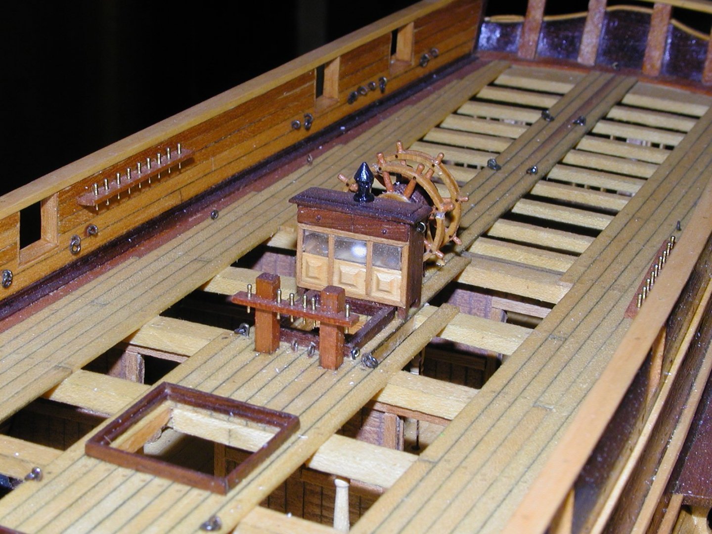
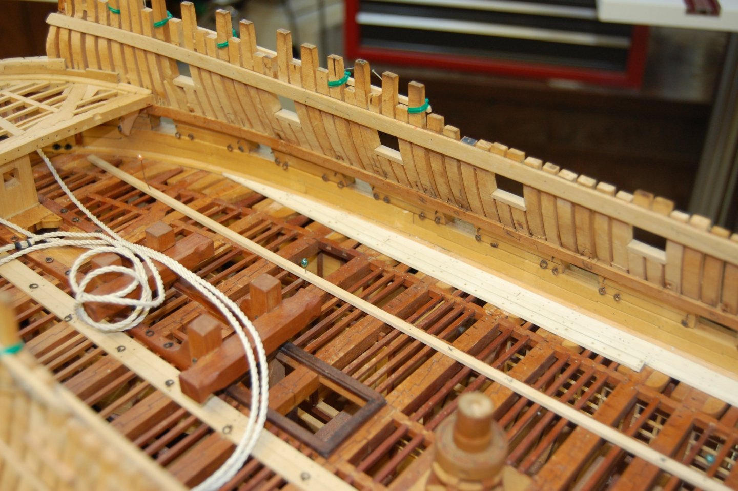
 John according to Peter Goodwin the water way and the margin plank was two different pieces of wood. . The waterway was a strake of specially fashioned plank worked fore and aft along each side of the ship across the ends of the deck beams. The function of the water way was to form a watertight seal between the side of the ship and the deck. If water was able to enter at this vulnerable area of the ships structure both the ends of the beams and the ships timbers to which they were joined would become rotten. It was in the shape of a L as a easy way of looking at it shape. The margin plank ran parallel to the ships side and fayed to the waterway. The function of this was to pre vent the normal straight deck planking from being tapered to a fine angle where it met the curvature of the ship's side at the fore and after ends. The margin plank was thus fashioned to receive the butts of those planks. I added a couple of photo's showing how I did this on my Confederacy and a photo showing the Alfred. John if you put the waterway plank at the bottom underneath the bulwark planking and then butt the margin plank up next to the water way that would be my way of doing it. I am not sure but am thinking that the bulwark planking and the spirketting are the same thing. Hope this helps sir.
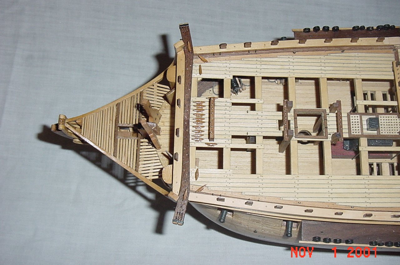
-
John could you share a photo or two of you deck? It would be a big help to us to be able to help you? Gary
-
Hi john this may help you. The drawing came from Model Ship Wright and the author was David White.
.thumb.jpg.99ae0fad138373de0418539f9280b798.jpg)
.thumb.jpg.eb31ae1e6fb484f0525f62079fe0e15a.jpg)
-
Hum wait till you ask your daughter were your phone is and she tells you your talking on it. I was a bit red face over that one. Well good sir am going to hold you to that part.😊 Gary
-
Looking good Mark and will follow along. Always nice to watch a real shipbuilder work his craft. Gary
-
Thank you Hubac's and I do enjoy his videos. I think a beginner would be helped by watching his rebuilding the Tally-Ho project and even I have got something out of it from his rebuilding the frames to installing the beams. Thank you again.
-
Thanks Mark it is Astonishing what they did with just a adze and a two man saw. . They were real craftmens of their time. A really good you tube video on how they did it is of Leo rebuilding the Tally ho and have enjoy watching him from the very start. Not every thing they do is just like 1760 but does give you that feeling and of course they use electrical. Now if only we can get Jim to make us one of those shipbuilding band saws that they use for building our little ships. Of course don't pay any attention to the fork lift. 😊 I think the bird is the real star and after you watch some of it am sure you would agree. 😍
-
I have to second that druxey. Mark the stove was a real joy to build and most of the info came from Arthur Bugler book, HMS Victory, Building Restoration and Repair. It gives you the full size dimensions and with out it would have been a pain in the butt. Gary
-
Ok guys, been looking for this term in all of my books for what it means and have come up short. It such a great term that they havn't even put it on Wikipedia but probabley show up in the future. 😲😆😜. O forgot good job Mark just love your updates.
-
Hi Vaddoc. Nice job so far and thank you for feeling me in on your build. As far as reusing the same holes this is what I do, well at least I try. I usually us pin's to hold things together and after finally finishing the parts install treenail's/trunnels in the holes. Every once in a while I end up with a hole or two out of place but use saw dust that is the same color to fill those holes. Thanks again for sitting me straight. No worry's sir am behind you 100 percent. Helping each other is what its all about. Gary
-
Hi Vaddoc. Just a question for you sir. Are you planning on putting filler blocks in between the frame/bulkheads. Once sanded down should give you a even better full surface to plank over. Most use balsa wood and can be picked up at hobby store's depending on where you live. Gary
-
Hi Jim. I have a couple, but they are made of metal and was interested in the one you got. Am also thinking about modifing one of them in to something more easily gotten in to smaller places. Thank you. Gary
-
Hi Kurt. Guess what, it showed up and for some reason I knew if I asked about it, it would show up. it did on the 24 aug. God bless Bob and wish him the best.
-
Hi Jim. Can you give me some info on the profile tool that you show in the second photo might just have to get one. Thank you. Gary
-
2021 NRG CONFERENCE
garyshipwright replied to kurtvd19's topic in NAUTICAL RESEARCH GUILD - News & Information
Thanks Kurt. St. Louis would be great and the others that you mention to. Gary -
2021 NRG CONFERENCE
garyshipwright replied to kurtvd19's topic in NAUTICAL RESEARCH GUILD - News & Information
Hi Kurt. Is there a possibility that the conference will be held on the east cost like Virginia , Florida,maybe some place like where the Constitution is in the future. Last one I went to was in Chicago and really had a good time. Thanks. Gary -
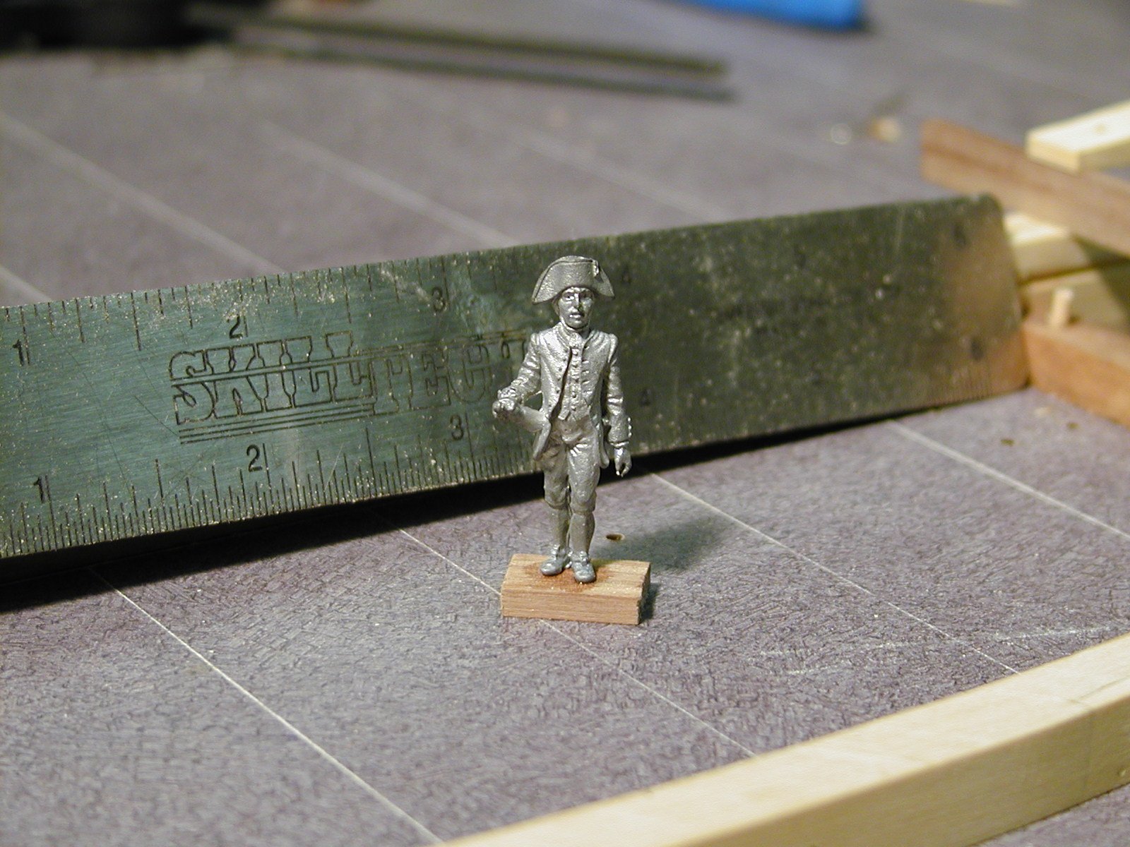
Hi Christian. Am not sure this will work but will give it a try. As far as any figures in a smaller scale am not sure but will check. It does seem that they have quite a few figure's to chose from but not sure on the scale. Gary
-
Hi Ryland and thank you. I like the shapeways figures to and seems they are really more in scale. I have looked for some in uniforms of the Royal Navy of Montagu time frame but so far have struck out. Thank you again. Gary
-
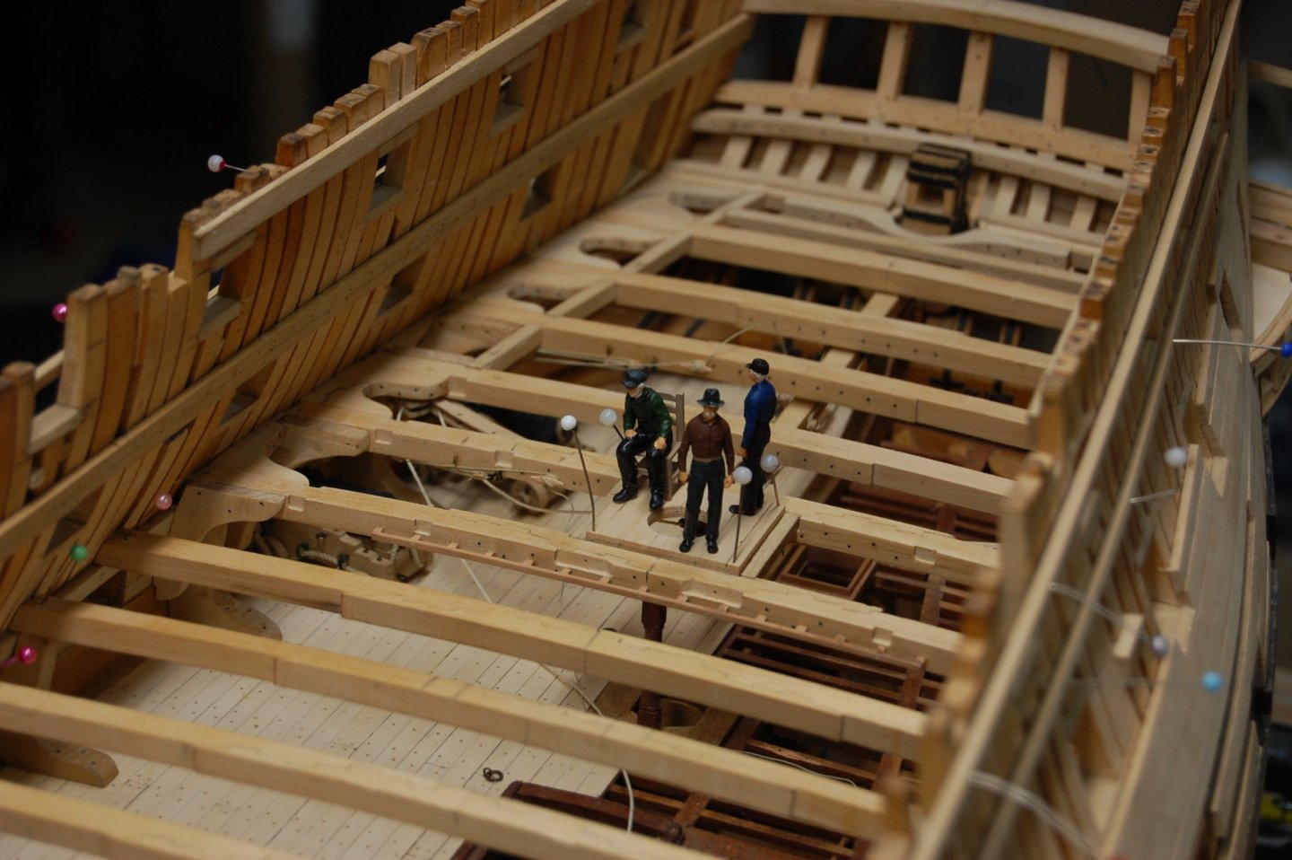
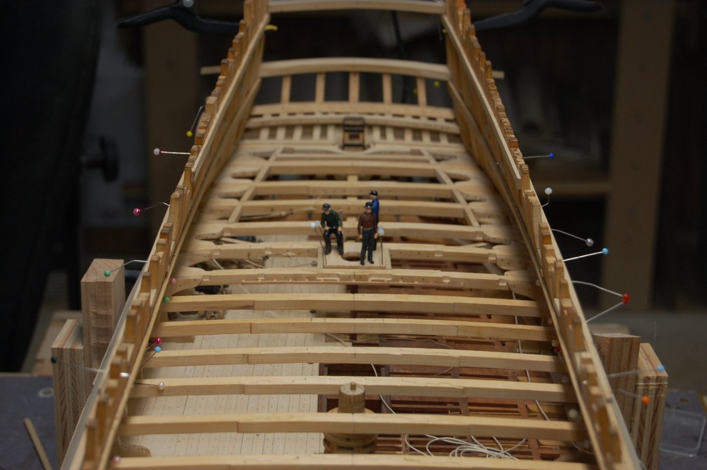
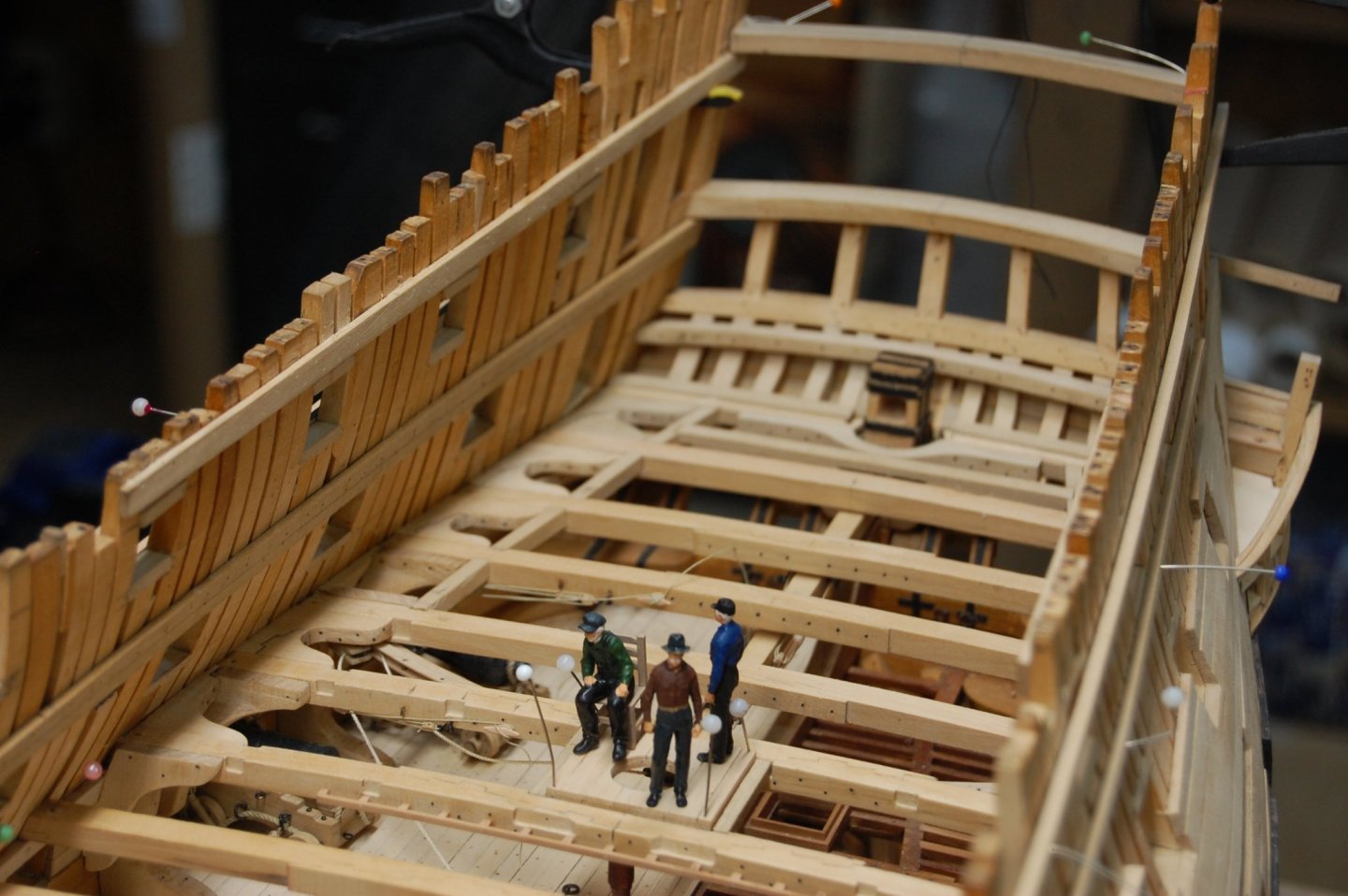
Thanks Mark. They do give it a sense of perspective don't they. Here is her first crew from earlier photo's and unsure of where they went. Maybe they was pressed on to another ship.🥺🙂 Gary

-
Mike your doing a very very good job and your log is worth me finding a seat, can some body please bring me a box of popcorn, easy on the salt. I would get it my self but some body will take my seat🥺. A few of your picture's took be back to when I was building Alfred's back bone, dead wood and the stem. Nice build and looks good. Gary
-
Greg I couldn't agree with you more. Now were can I get one of those CNC carvers. Very very nice marsaly and enjoying looking at your build. Gary
- 589 replies
-
- 3
-

-
- le gros ventre
- cargo
- (and 1 more)
-
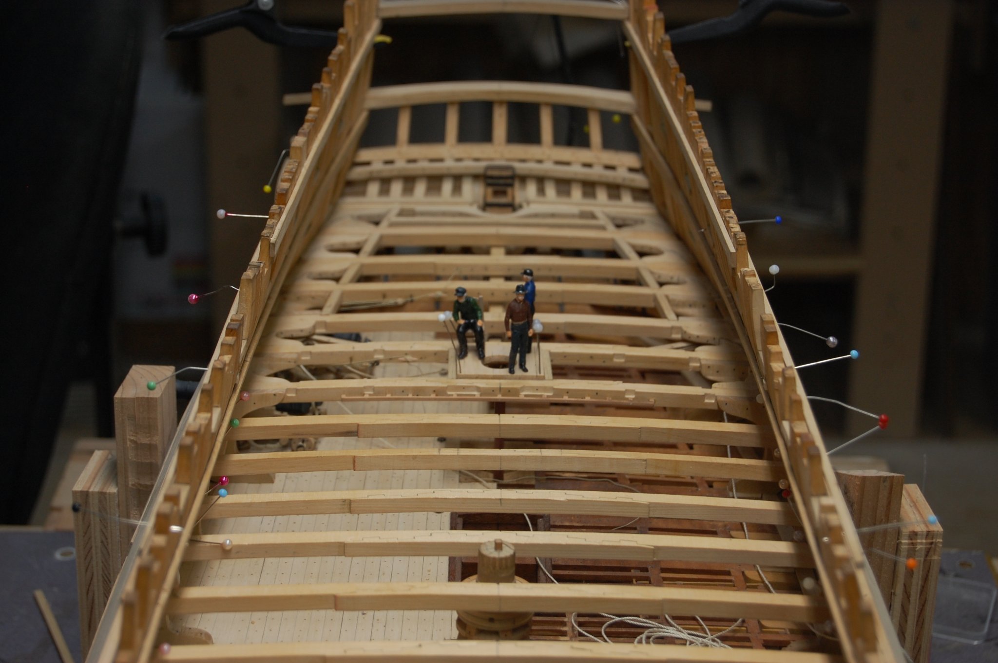
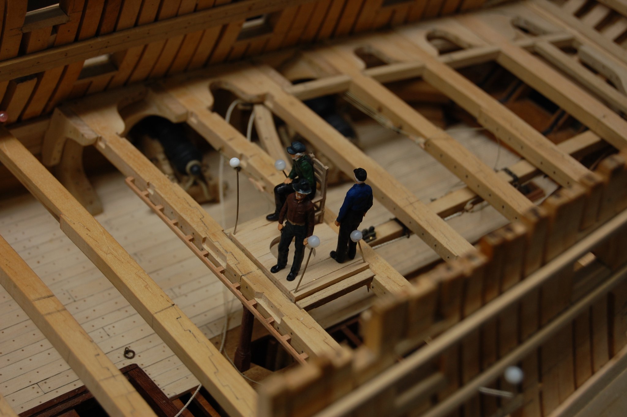
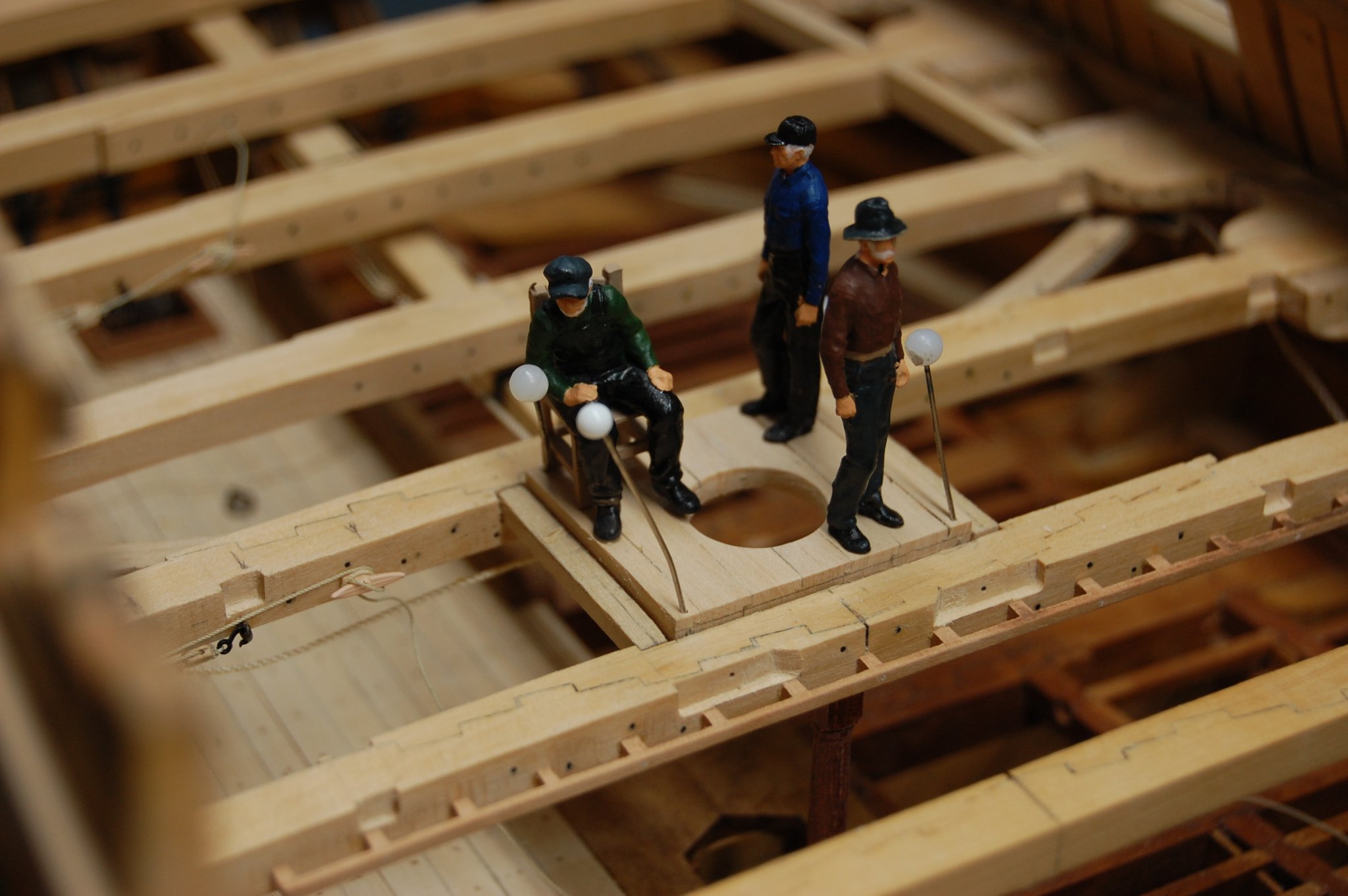
Thank you VTHokiEE. The journey with her and the endless research, the people here who have helped me to understand her and how things fit together has been a long road. Her building has sometimes been good and other times makes you want to pull out your hair. Of course I would not change a thing. 😁
-
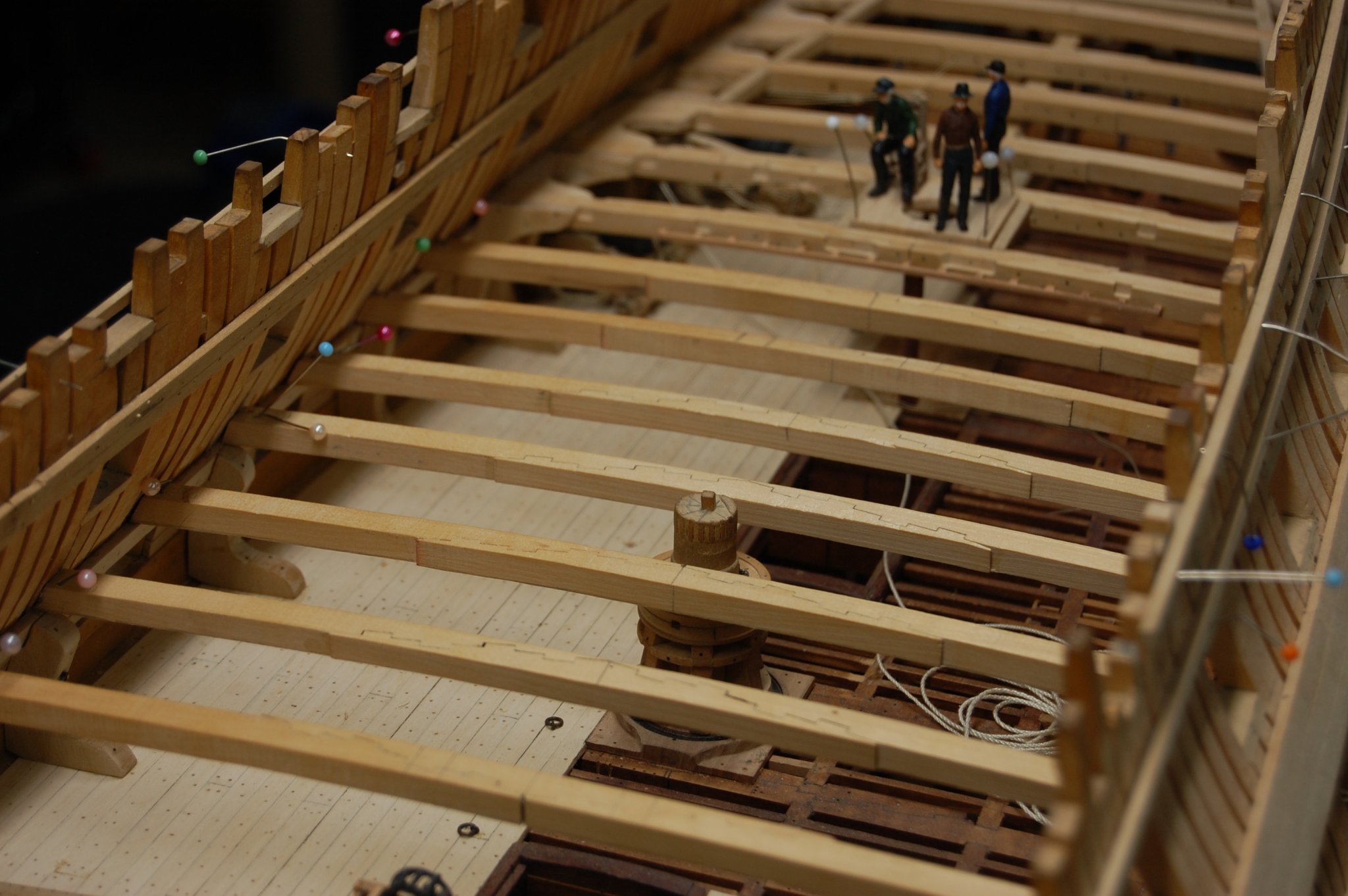
Hi every one. Finally got my camera charged up and took a few photo's, hope you enjoy them. The figures came from shape way and ideal of using them came from Chuck. Spent the day painting them and have white hair like their owner. 😁Gary


- 842 replies
-
- 23
-
-


.jpg.47d07d9a5211c3a0ebccbae84a82b553.jpg)
.jpg.c287a6d92f05ecf54f6a9453897c1eaf.jpg)