


garyshipwright
-
Posts
939 -
Joined
-
Last visited
Content Type
Profiles
Forums
Gallery
Events
Everything posted by garyshipwright
-
 Hi druxey and Mark don't forget the sholes/soles. It seems I forgot to add them. Ok I know but thats my story and am sticking to it. 😔
 -
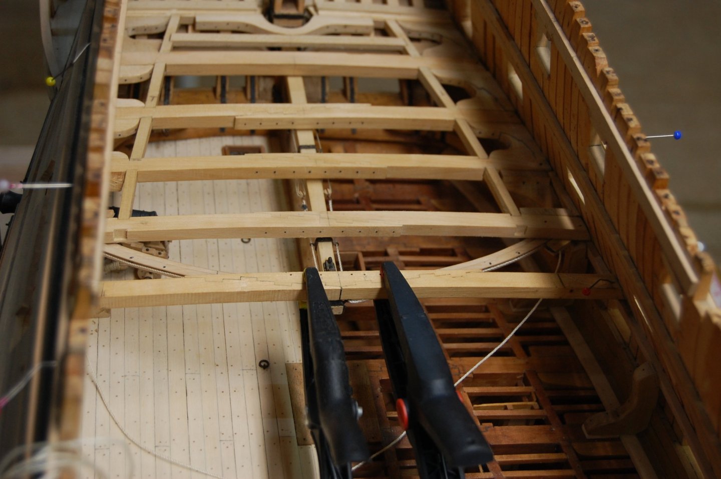
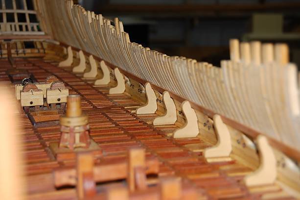
Mark am not sure where I found the information on that spacing and will look and see if I can find it. I think you might have to be the ship wright in this case and I added a photo so you can see what I did on the ones I made. I think this is a better photo showing the space then the one above.
.thumb.JPG.55c8bb91f47a709c0275e641e732d360.JPG)
-
Mark you may already know this the space between the standard's and the water way should be open so it wouldn't block the movement of water to the scuppers. I found out that fitting the back of the standards to the wall first and the bottom to be a good fit then I cut the outside profile. Just my way of doing them and also do the lodging and hanging knees the same way. She is look good to by the way and was wondering are you going to install bolts in them? Gary
-
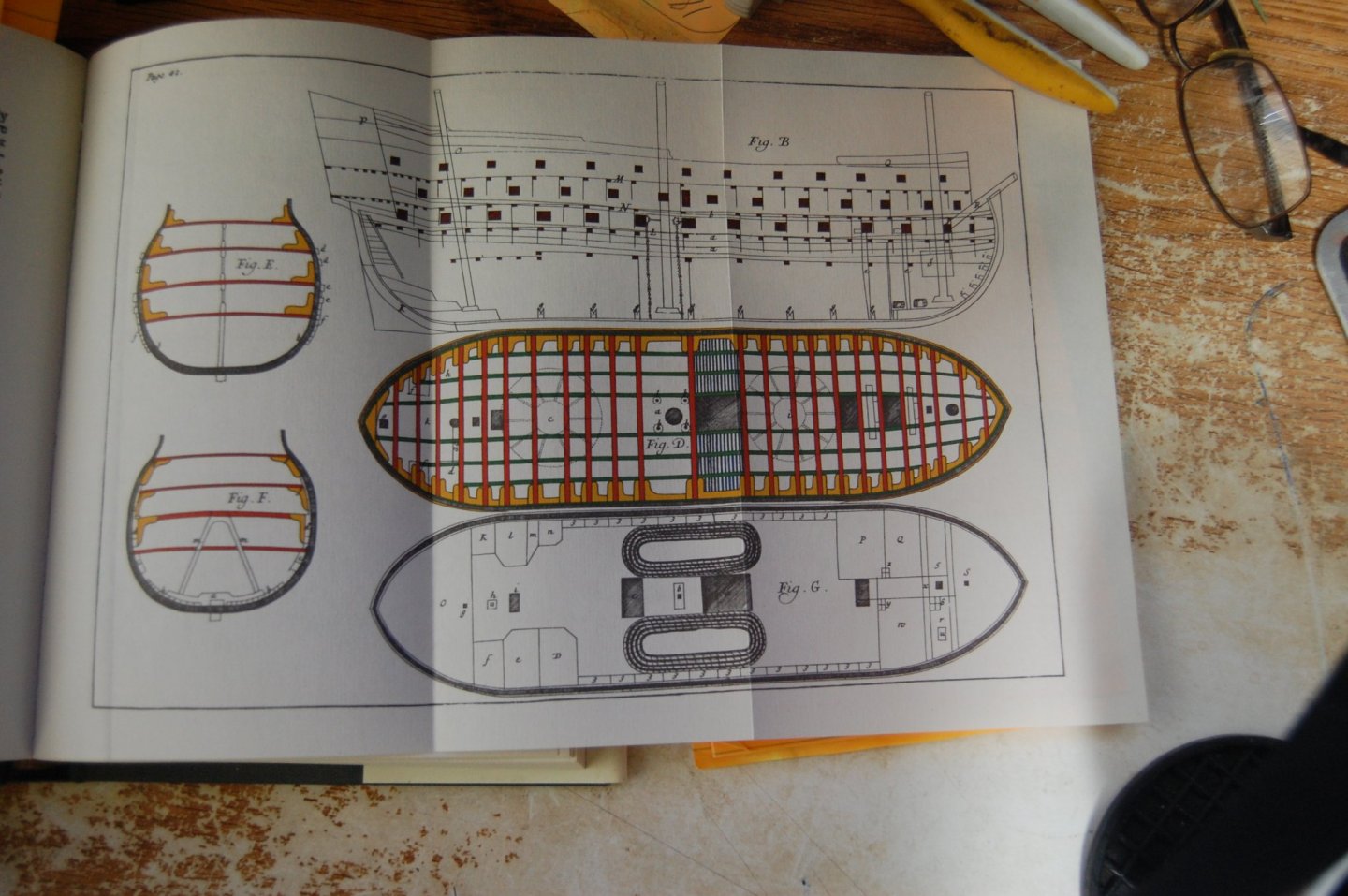
Yes sir it is. In the book by William Sutherland in 1711. He says Fig D is a plan of the lower Gun deck, consisting of beams, Carlings, Ledges, Knees, Partners, Capstand,s, Cross pieces and bits. The Red in this plan is beams, the yellow, knees as arms to hold the knees and sides together, the green carlings, the blue is ledges and the bounding of the plan repressents the ships sides, out board plank yellow, the Timber black and the inside plank Green. Gary
-
Hi Gaetan and I would total agree with you and saying that it was between 1750 and 1760 is total wrong and probably over a period was larger.
-
Mark I am going to up loaded a photo of Sutherlands plan of the ship which shows this layout, that is as soon as my camera is charged. I think druxey hit the nail on the head, each shipwright some times had to make up his own mind to what was best for the ship he was building, and how precious timbers could be used in the building. When iron knees came in to use more am sure that many of the problems on placement of knees became a thing of the past. One thing that I find odd is that Steel and the Shipbuilder's Repository doesn't show or tell us about the direction of which side the hanging and lodging knees placement. Steel does show us them on the gun deck plate but are not shown on the upper deck plate. I find these things a little odd, but will continue to look for a answer. Sure would be nice to have that time machine right now. I did take a look at Stalkartt Naval Architecture 1787. Says the lodging knees are generally disposed on that side of the beam, which makes them the most without a square and the hanging knee placed clear of the ports and of standards on the deck below.
-
Thanks Mark and Mark. Just more question and answer good sir's. When the rule was made it was based on William Sutherland, Shipbuilding Unveiled 1717 and those passage can be seen in Peter Goodwin book Sailing man of war page 75, bottom right hand side. Thing is am not sure how many folks have read his book or the 1711 The Ship Builders assistant but if you have would love to hear your view points. When you look at the first page of the 1717 book it seems to reference the 1711 book. Now you wonder how am able to read the 1711 book being of its age but Jean Boudriot Publication in 1989 did a reprint of it and I just happen to pick up one for my young library. I also have a computer copy of the 1711, 1717, 1729, 1755, 1766, and the 1784 to help me research them. Now in Goodwin book on page 75 he says The hanging Knees are placed in the same position with the timbers, bolted both to beams and timbers for holding the beams to the sides. He goes on to say The beams ought to be placed one between and one under the ports of each deck, with this caution that the hanging knee may be placed clear of the ports and lodging knees abaft the beams forward and afore the beams abaft, for the benefit of making these knees as much greater than a square or as obtuse and angle as possible for the easiness of procuring them. Now what one doesn't read from Goodwin is in William Sutherland book which at one time was only a dream to own. In the book of 1711 page 36 at the bottom of page, he says, There ought to be always this special remark in spacing the beam of each deck, that the knees of each beam may be place clear of the ports, that you may not be put to the shift of using dagger knees, or those that are crooked, which are seldom strong, and more difficult to purchase than straight. Now on page 39 he says, The beams ought to be place one between and one under the ports of each deck, with this caution, that the hanging knee may be placed clear of the ports and the lodging knees abaft the beams forward, and afore the beams abaft, for the benefit of making those knees as much without a square, or as obtuse and angle as possible for the Easiness of obtaining them.
-
Your welcome Mark. You could put a hanging knee on the aft side which would ensure one hanging and one lodging knee. From looking at your drawing your sheave at the side is clear of the aft side of the beam so I am not sure why you just don't put the hanging knee there. As you can see on mine I also had a standard to deal with. Another item comes to mind is your sheave in the side or attached to the underside of the tiller sweep? Gary
-
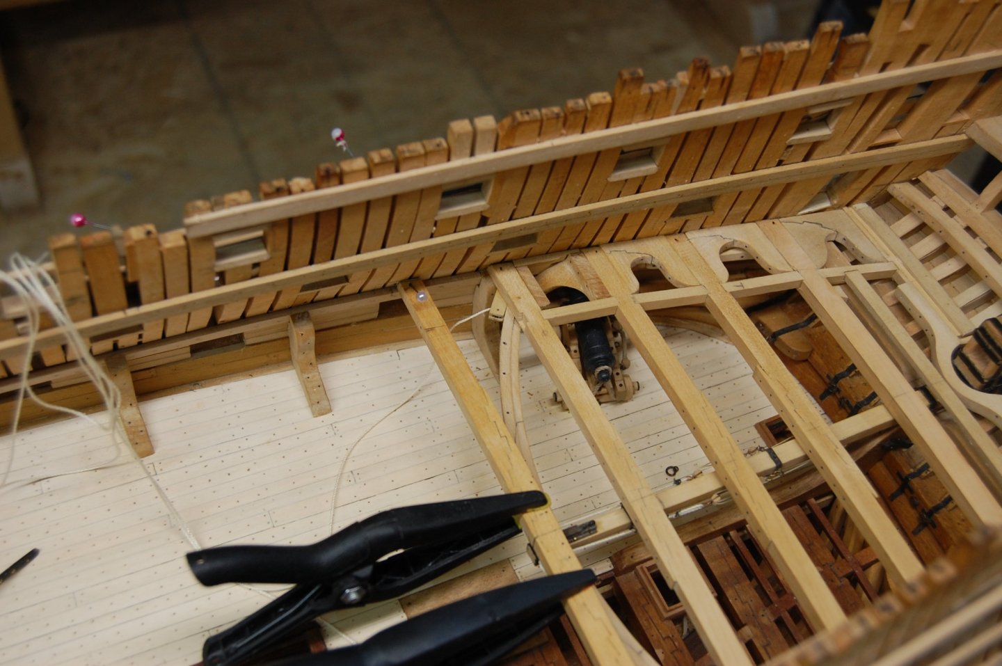
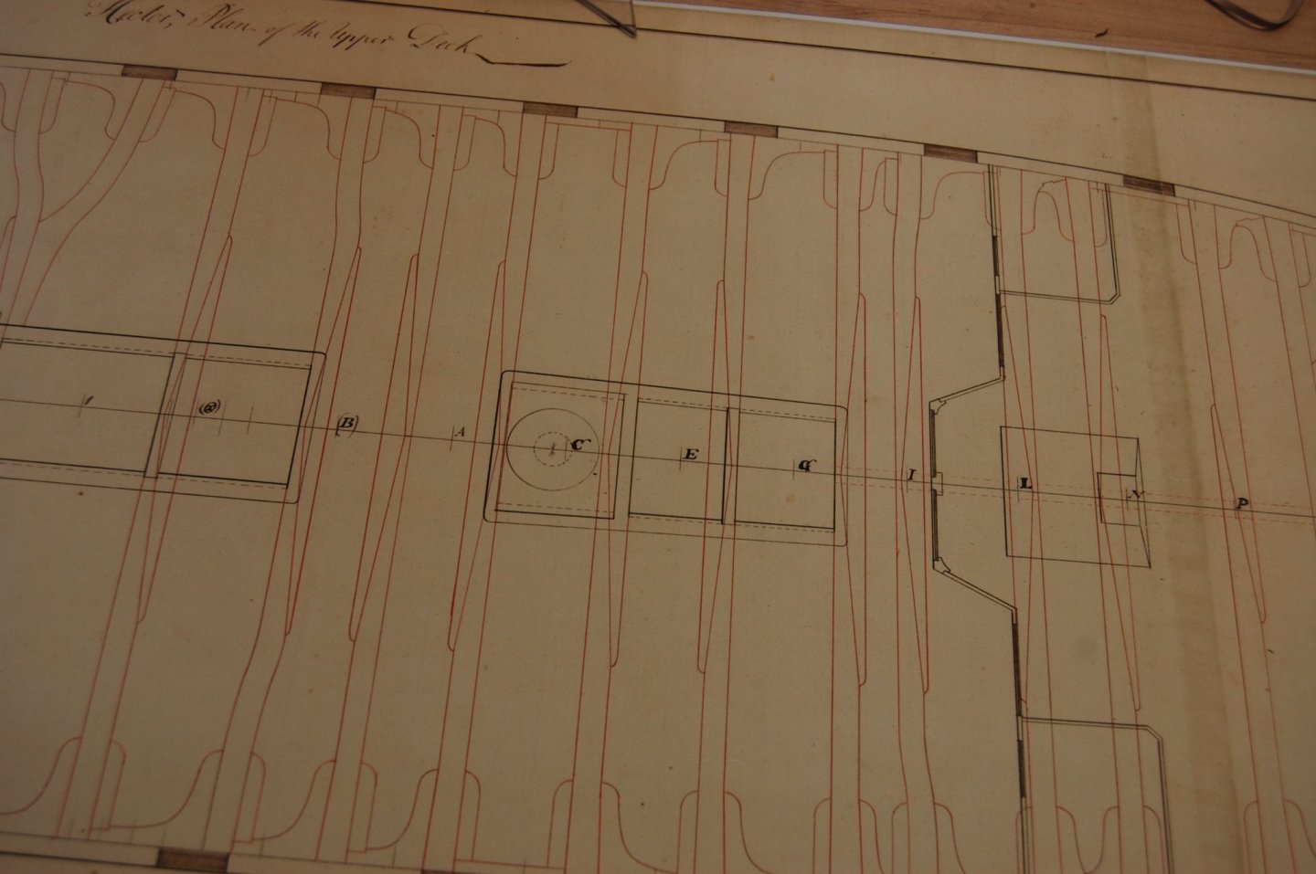
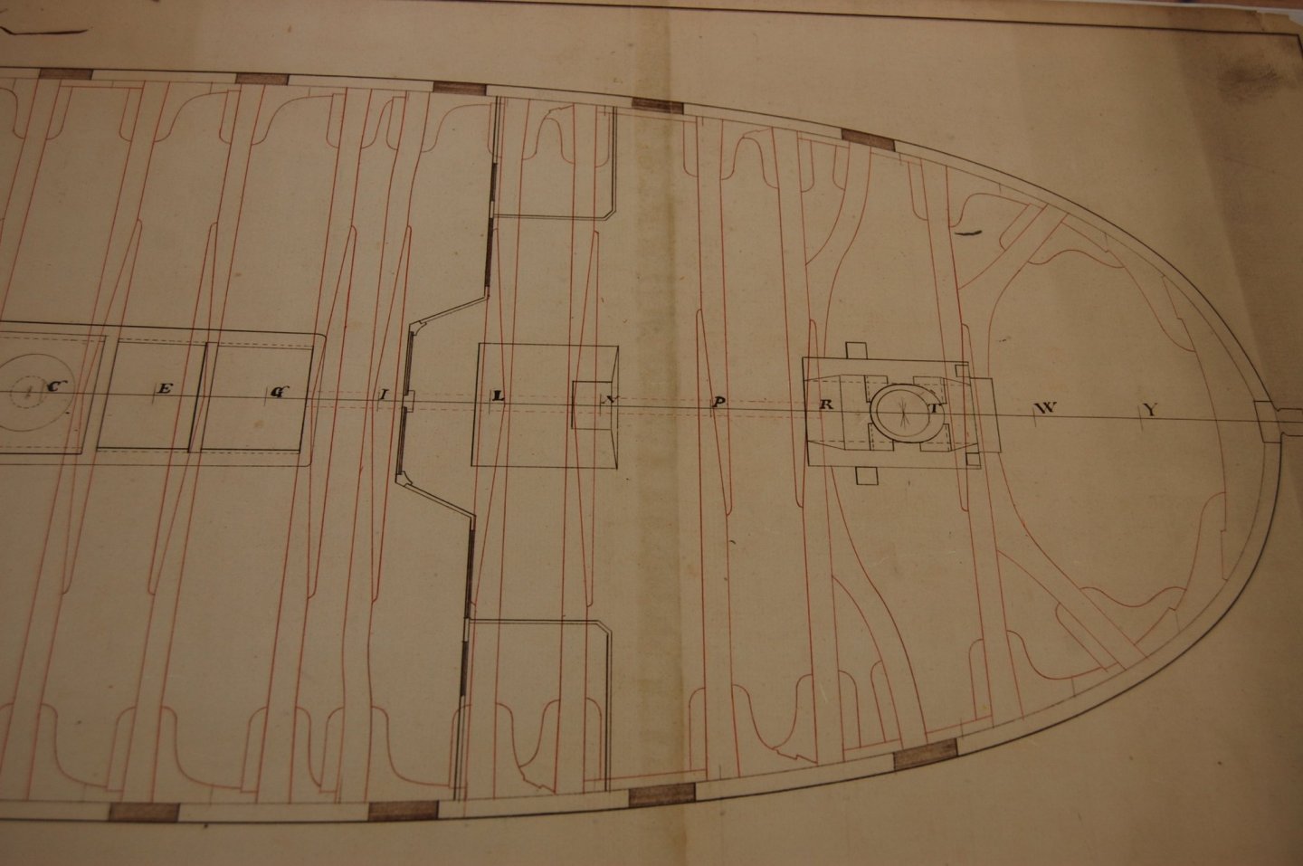
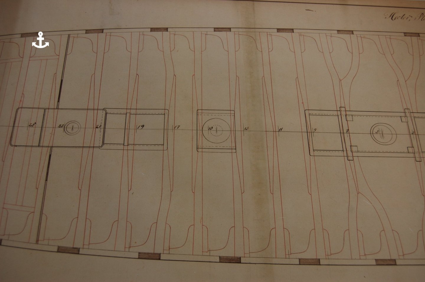
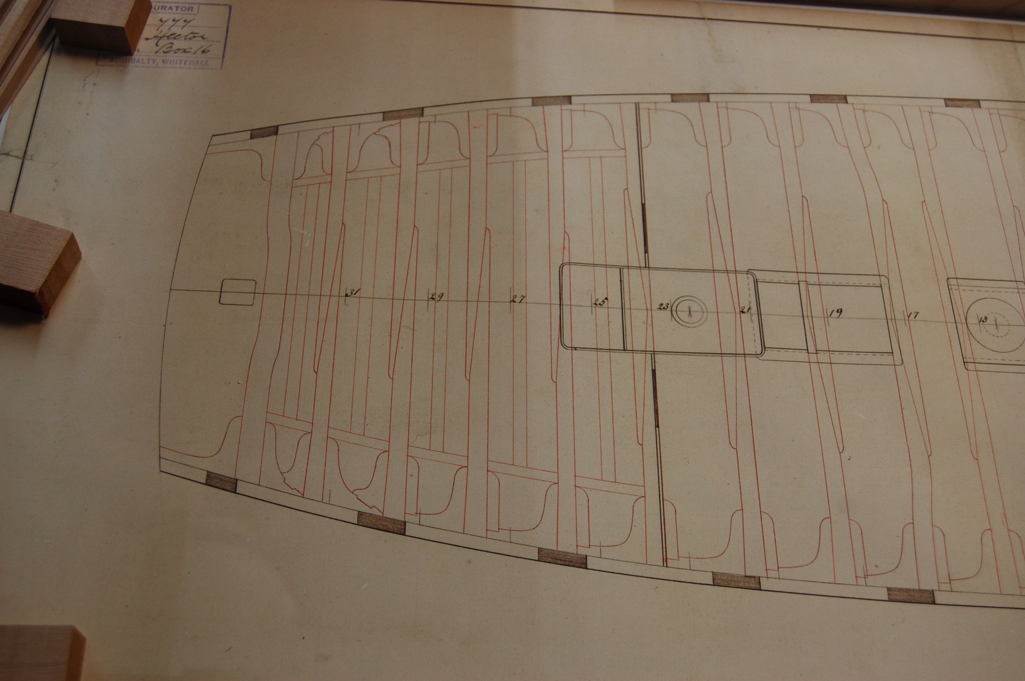
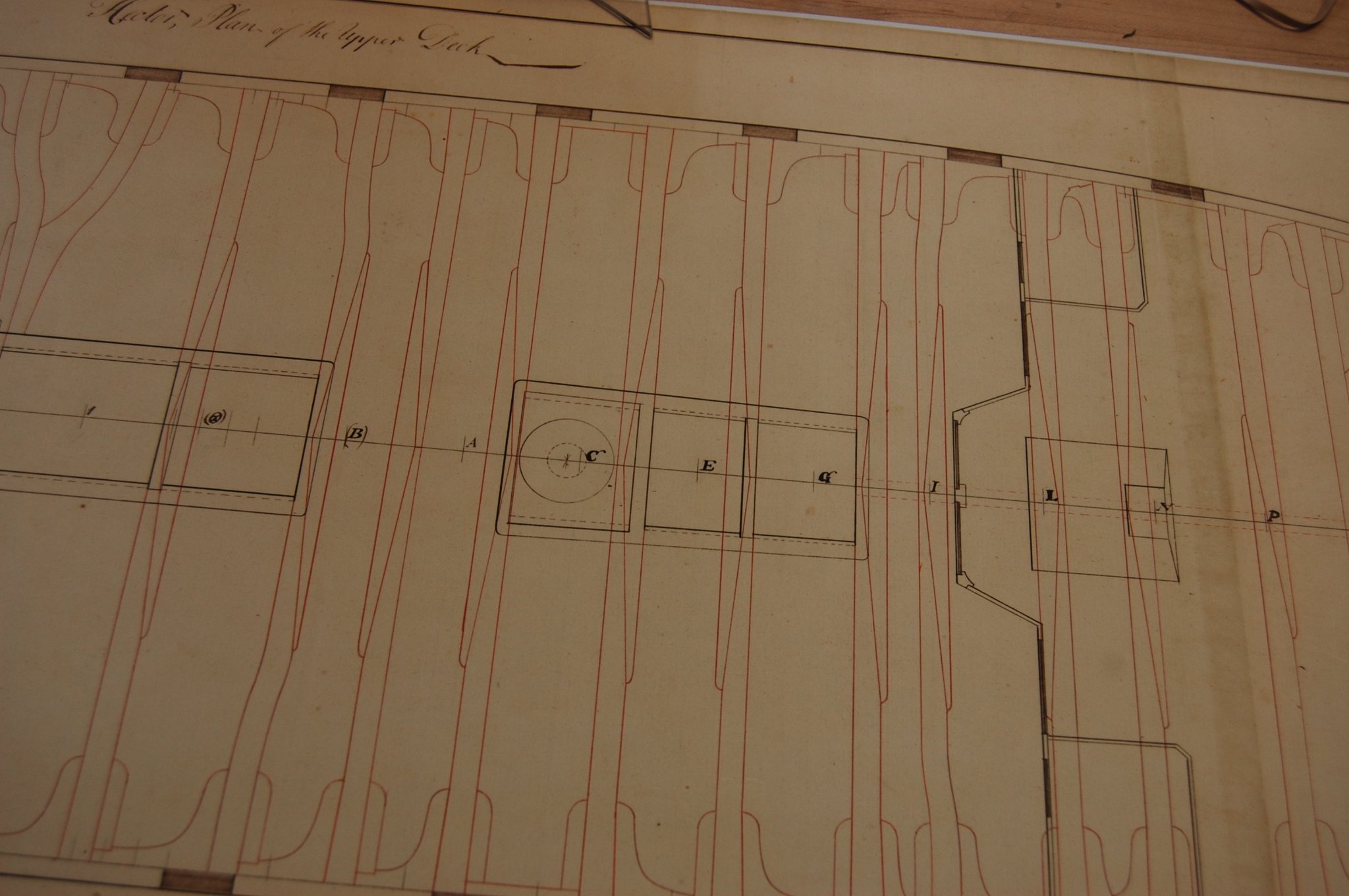
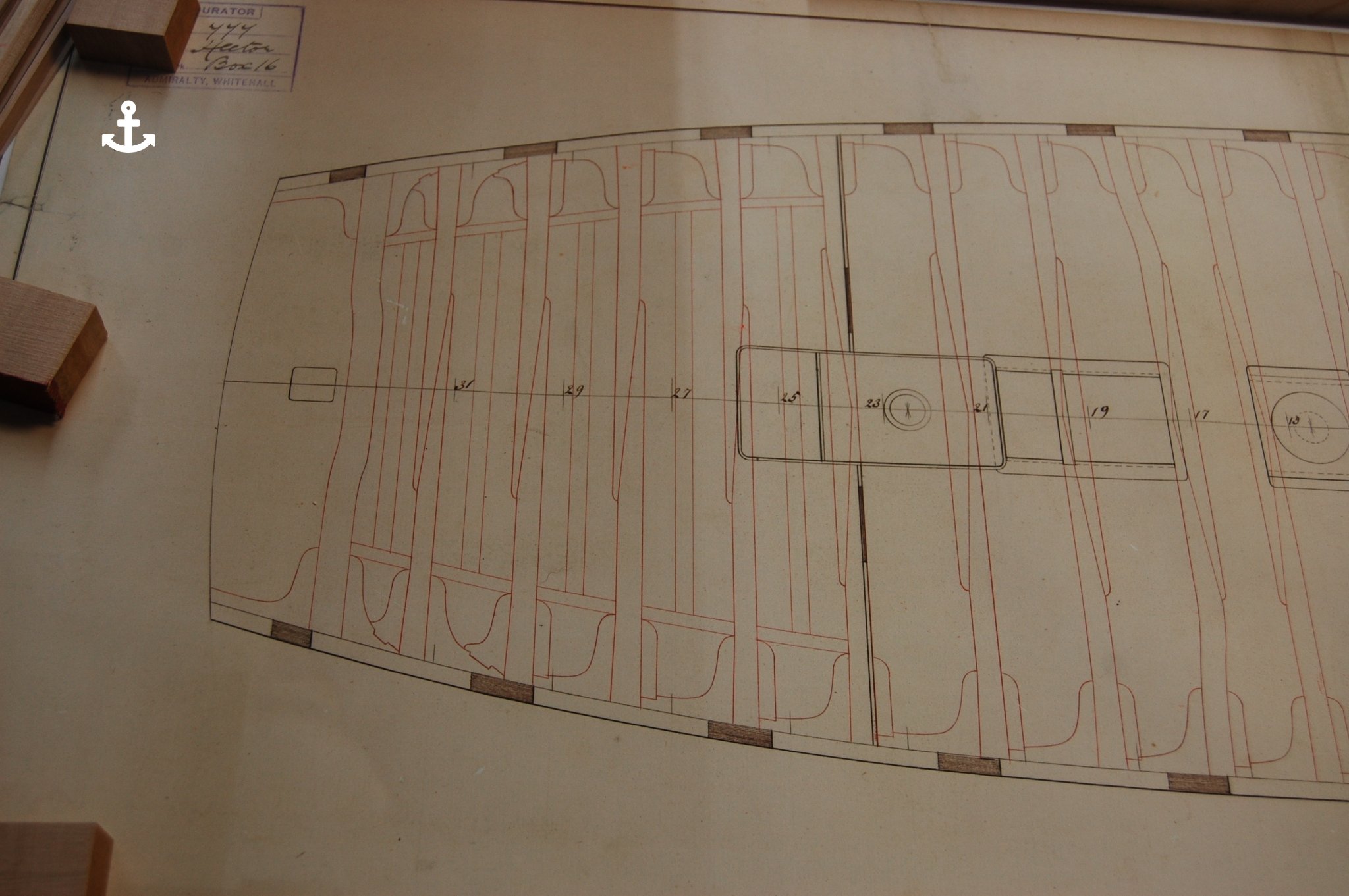
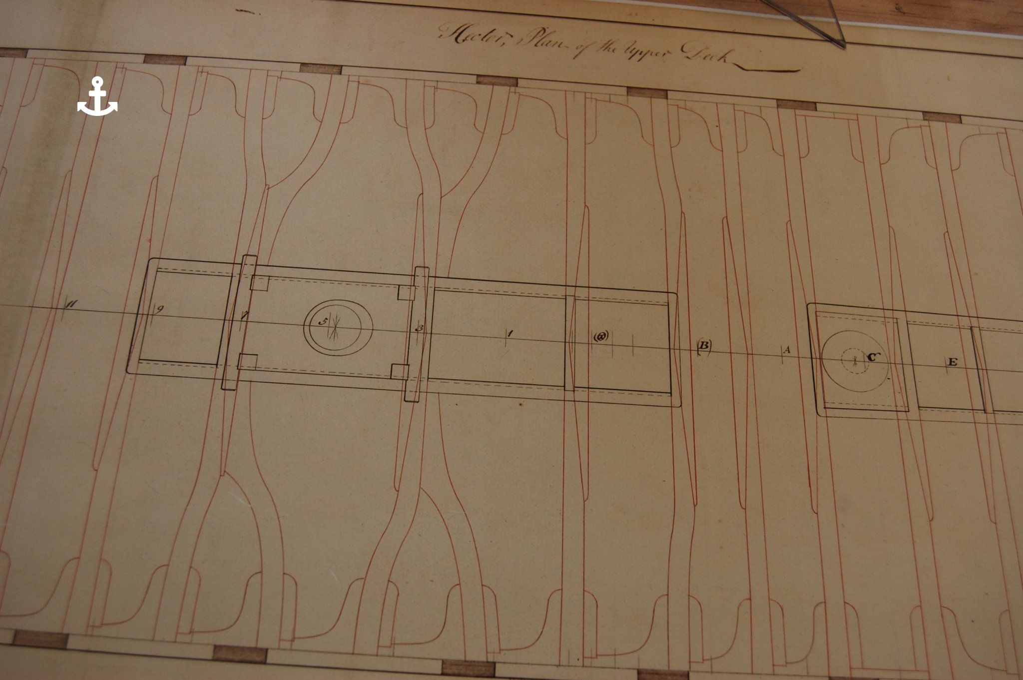
Mark how come you just don't put in two lodging knees between 15 and 16? Here is a couple of photo's of Hector which may help. Good ideal of putting in a dagger knee, looks good. I do believe that having a hanging /lodging knee on the ends of the beam was probably the most important. Mark if you look at the second beam forward and its arm your noticed that between the arm and beam it has two hanging knees and a double set of lodging knee between beam 2 and 3 and has a missing lodging knee on the front of the arm. Wouldn't you have as much stress here from the fore mast as you would at the main mast? Sleep tight.

-
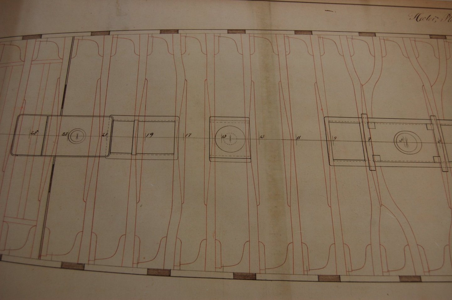
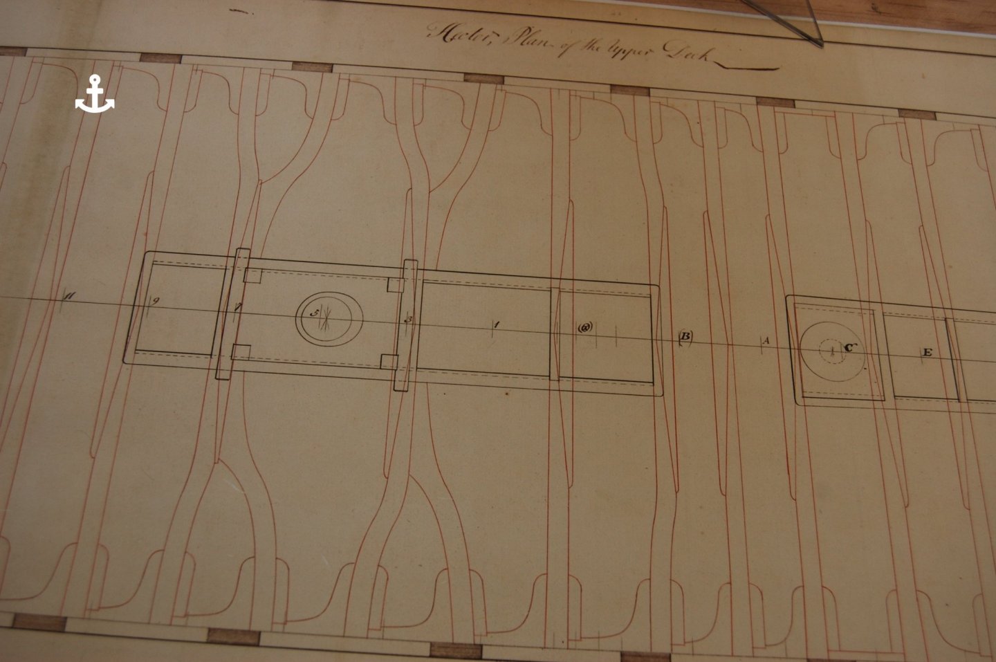
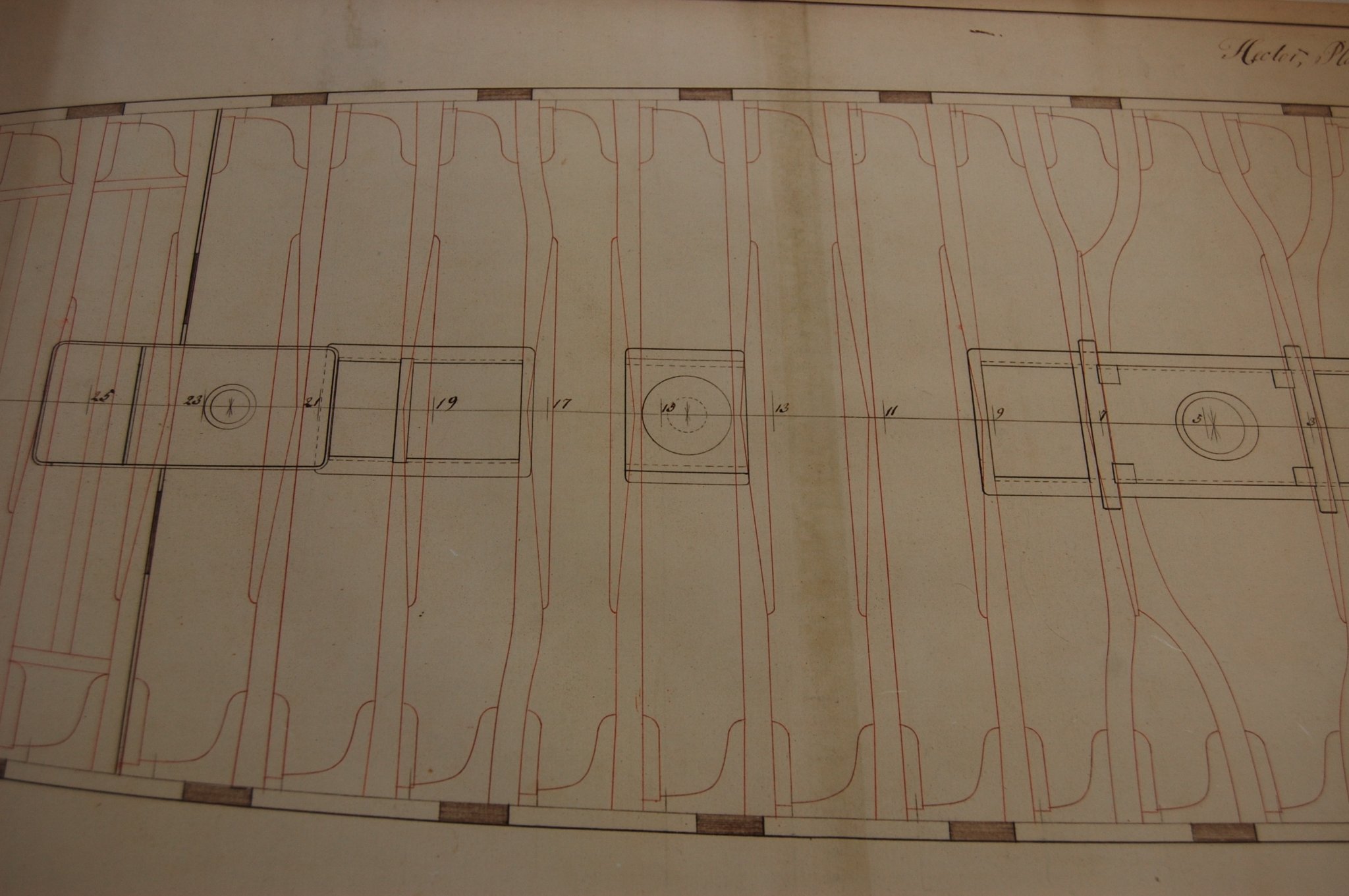
Hi Mark. No sir I have not seen the original other then the one in the AOS book. Looks like what I was saying earlier that the ship wright shifted the hanging and lodging knees forward and backwards depending on the best place ment for them much like what we are finding out on our build's. I did find a answer for my question on Hector and Vengeance of 1774. Fincham said that the lodging knees were on the aft side of the beam on the aft side of the middle line and on the forward side on the forward side of the beam. So it seems am going in the right direction after all. I did find the middle line is at the forward capstain. It does seem that the layout of the upper deck was just a bit more hectic.
-
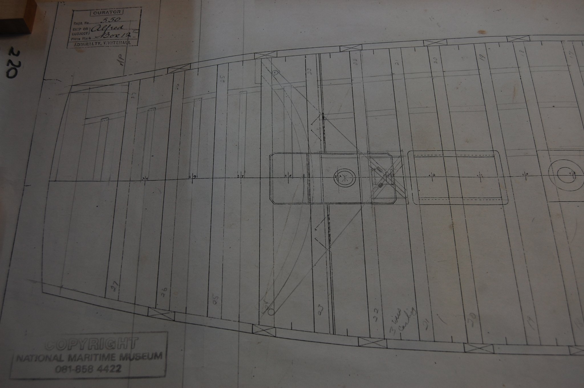
Mark I do believe that the placement of the lodge knees and hanging knees was changed around the 1750/1760. I believe that you could go back to Charles second, of the way knee's were laid out. I have been looking at this and belive that the plans I show of the Vengeance and Hector is right and really didn't have any thing to do with were they were built. If you go back in Endsor book The Master Shipwright's secrets, to page 185 you will see that the beams of the gun deck and upper deck has the hanging knees shown as druxey said and the plan is of the Tyger 1681. Now if you jump to 1711, in William Sultherland on page 42 he shows what I believe is a plan of a 3 decker showing the placement of the hanging knee's aft on the aft beams and forward on the forward beams. Now if you move forward to Dorsetshire built I believe to the 1745 establishment on her upper deck it shows, the same. Now the plan of the arrogant of 1761 shows a change of were some hanging knees are on the forward side and some on the aft side. Now we get up to 1774 where Hector and Vengrance both come in to play. Both have the same set up and shows lodging knees on the aft side on the aft beam's and on the forward side of the forward beams which I believe is right and takes us all the way up to Fincham 1853. Now when you look at Reess Navy Architecture of 1819/1820 he shows on the gundeck plate 5 showing 21 hanging knees were on the aft side and 10 were on the fwd side. Steel 1805 shows in plate 5, 21hanging knees were on the aft side and 10 was on the fwd side. Now in Fincham book of 1853, Outline of shipbuilding, pg 46 gives us this. It doesn't give us the layout of the hanging knees but the lodging knees which is in line with the Hector and Vengrance plan. The lodging knee were placed on the after side of the beams before the middle and on the fore side abaft, that the knees might be obtuse angles with out a square for the ease of getting them and that they might be of less expense. They say the middle line which I believe in Hector case and Vengeance that the middle line was in aline with the forward capstain
-
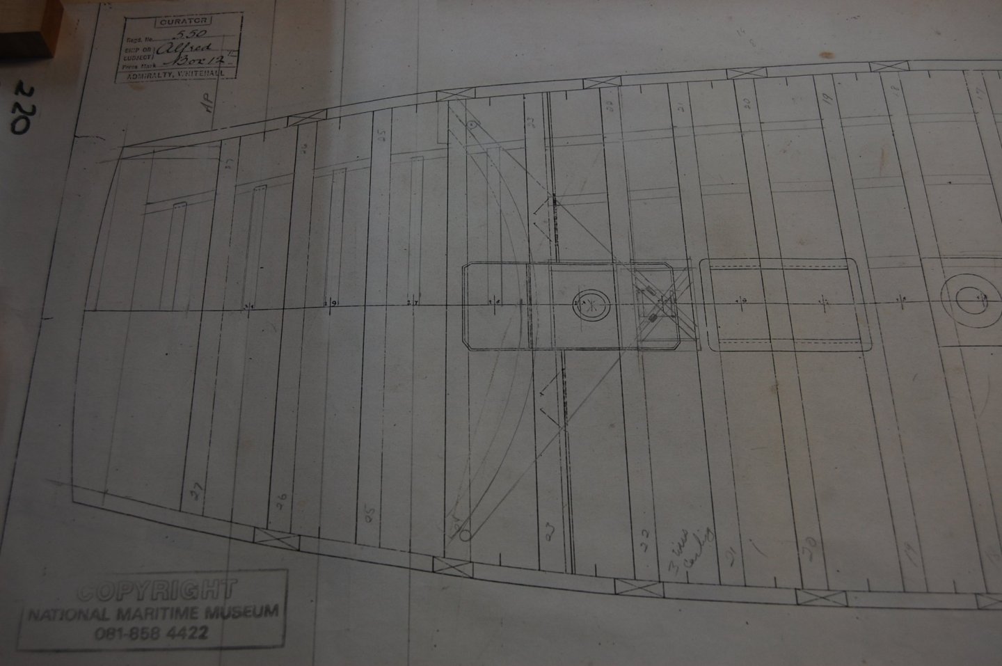
Mark am still looking for this rule that says that they went on the aft side aft and the forward side forward. I brought this same thing up in my log about the placement of hanging knees and strength wise. Most deck plans don't show the knees but I have found with the help of other's a few plans that in fact show the placement and seems to show the hanging knee's on the fwd side. If you can mount them as you have shown then why would you use a cast knee when you could use a normal hanging knee. Was this rule so enforced that the ship wright was over ruled and used up timber that was hard to find. As druxey said If I were master shipwright I might be tempted to place 14A forward of the beam as well.... and total agree with him. i find on Montague/Alfred that I have ran in to the same problem that you have and probably will shift them to one side or the other but at the same time try to maintain the rule. On the other item using a contract of 1770 it say's to have four rings and two eye bolts to each port and two of the ring bolts to be placed in the second timber from the port , the ring to be 5 inch's in Dia and the eye bolts sufficiently open for the tackle hooks. It also said that there are two eye bolts over each port for lashing the guns. More to come
-
Outstanding Mark. A real joy to wake up to seeing your masterpiece. Thank you for sharing her. Gary
-
Thanks Hubac's and druxey. Druxey I do have a book on the Barnard Dynasty c 1697-1851 writtern by John Barnard who traces the history of four generation of the Barnard Family of Ship builders and they built a lot of ships for the Royal Navy and doesn't really say any thing on the knee's, which I didn't think it would but the Hector was in the book. Am sure they had a good understanding of how they were to be built for them which as you said earlier was a experment or they approved it. Thanks again.
-
Druxey even through they left things out that was normal known, could things have been left out because they didn't know how to show it in the finally shape and its fitting was left up to the shipwright like the helm port transom which doesn't show on her upper deck plan like the one below?
-
Well to throw another monkey in the mix I found another one, the Vengeance built in 1774 also of the Royal Oak Class designed by Williams and built by Randall, Rotherhithe and shows the upper deck hanging knees, which most are on the forward side. I take it that she was also built in a merchant yard. Well this brings up more question for me. If the hanging knees are post to go a certain way, should this have been inforced by the inspectors or was this just over looked. Both ships were drawn up by Williams so if he drew them showing the knees which is right and which is wrong. Even more question and no time machine. Well I took another look about were Dorsetshire and she seems to have the same set up with hanging knees on the forward side of the aft beams . Well this gives one something to ponder.
_RMG_J3247.thumb.png.7a3f2db71eeae6792f9009f98f88afc1.png)
-
Thanks every one and what if I said that when it came to the upper deck, if I said that depends. If one looks at the lay out of the gun deck of the Hampton court and the Dorsetshire it does in fact show on the gun deck that the beams on the forward side of the pumps, were on the forward side and the beams, aft of the pumps on the aft side, so you guys are right, they could have this lay out. When I installed the knee's on Montague gun deck this is how I installed them but on the upper deck it's not the same. Now when you get to the upper deck looking at the Dorsetshire of 1757 you will noticed that they don't follow that lay out of the gun deck but in fact are on the fwd side of the beams but Hampton Court does keep the gun deck lay out when it comes to the knees. If you look at the plan of the Dorsetshire on her upper gun deck 18 of the hanging knees were on the forward side of the beams and only 5 was on the aft per side. Now another plan that I have been using is the upper deck plan of the 74 gun ship Hector of 1774. This one shows that 21 hanging knees on the forward side and only 7 on the aft side per side. When I look at the layout of the lower deck gun ports and the upper deck beams lay out I find my self seeing that normal hanging knees would fit on the fwd side easier then on the aft side because of the gun port below it. Plans of the Dorsetshire and the Hector shows this wasn't always true that they were not always like Hampton court on the upper deck. Can anyone show me were this was written that this was done doing this time frame. Finding plans that show the placement of knees is rare, and makes it just a little hard but if you have one that shows this please show it and would be most grateful for adding to our knowledge. That why I asked would it matter on which side it was installed on for strength. Sorry if my question confused any one.


_RMG_J3111.thumb.png.c48d54b7f1f46ddbb00f5a9c50dc21f2.png)
-
Hay guys have a two part question. On the hanging knees do we know what side those would be on such as on the aft side of the beam or the forward side? Also for strength wise would it matter if it was on the fwd side or aft side? Cast hanging knee's depending on the placement could take on a large curve in order to miss blocking gun ports adding on to the amount and size of the timber itself? Your thoughts on the question would be most grateful. Thanks in advance. Gary
-
Hi Richard. I would go with Greg's 6 inches, and on Montague a 74 gun ship she has 6 1/2 inches thick at the top. On another note your build looks very good and will be watching you bring her to life. Just a ideal but you could scrap the insides which would keep down the dust. Gary
-
What do I want for Christmas
garyshipwright replied to Worldway's topic in Modeling tools and Workshop Equipment
My Wife also asked me that same question and told her, for my family to have a very good Christmas and a cure for this bug. Happy thanksgiven guys -
Thanks Mark and druxey your comments help keep me going, of course I have to thank the Swan guys, Greg and David and their books for showing me some ideals that really help make the job a whole lot easier, such as how Greg would take a over size piece, get the joint to fit first and then cut out the rest of the item. Gives one lots of wiggle room. I take a over size piece and fit it to the wall and then cut out the front curve shape along with the upper edge of knee against the beam it self. Greg shows the stem and dead wood in vol 3, page 18 and 20. Another thing to some that's not sure is take a piece of card file to fit the space. Put rubber cement on the open side and then clip it in place and the shape can then be filled in with small pieces to get the shape of that area. Once again thank you.
-
Hi Guys. Have a question about the messenger rollers time frame when they were used. According to Peter Goodwin, The Sailing Man of War, page 156, he says that they came in 1790/1792. Does any one know if they was in use earlier then this? She was broken up in 1818 so adding them as I show her would that be to much of a reach being they didn't come out till 10 years later? Also how did the messenger round the coner in the manger it self or was it helped along by the crew to do this taken away hands from the capstan? I know it was three question but curious minds are wondering. I know it would be nice to have a time machine, but your thought's would be greatly appreciate. Thanks. Gary
-
Siggi one of the contract's I have, time frame wise ,1770 and also used in 1775 says that the gun deck and upper deck had 11 per side. I looked for the number of standard's in a couple of books, for your time frame but could not find the number, other then the number of them in your post. My reason for the question was if there is only two standards on the gun deck per side where would that placement be. Maybe as you said in the middle of the deck. It does say the iron ones on the upper deck were place under the forecastle and quarter deck but still doesn't say where. I added a picture showing the ones on my gun deck. It may come down to, she didn't have many, just what the establishments said. Siggi I was able to go back, contract wise to 1755 to the 74 gun ship Warspite and it said that there was 13 standards per side on the Gun/Upper deck. Then I went forward to 1763 to the Marlborough and seems to have been reduced down to 11per side per deck. I wonder if any one has contracts that takes us back even further. Sort of like a time machine. Ggary
-
Hi Siggi. Question, does it say where these standards are located? I am looking for a answer but so far have not come up with a answer for you. Will be back? Gary
-
Thanks Richard, I take a second look and you just may be right if I can mill out those holes and doesn't make it weak. Gary
.JPG.7d8e38e96dd989e604c7d7df4efe6be7.JPG)


_RMG_J3247.png.67b1c961a60c63a1140588231f46e87f.png)


_RMG_J3111.png.9a9b0c9de00bf6668269ec3ec36ed0c3.png)