garyshipwright
-
Posts
939 -
Joined
-
Last visited
Content Type
Profiles
Forums
Gallery
Events
Everything posted by garyshipwright
-
 Hi Roger. Thats what we were talking about in the above post and the chuck would have to be able to overset the center of it up to a 1/4 inch. Thank you for you post. Gary
 -
Mark I seen photo's or model's, not sure which one but it shows the pillars as having hinges at the top so they could be pushed up out of the way for working the capstan, but as druxey said they may of just been moved out of the way for working things. Gary
-
Hi Richard and no I haven't given those much thought and do have the small OJT chuck with the adjustable back. From reading the description and specifications on their site it lead's me to believe it only very small movement's for centering very small drill bits. Gary
-
Hi Alan. Not speaking for Karl but the photo you show of the gun is the English way of rigging the breech and if you look in Boudriot 74 gun ship vol 2 it shows the breeching as Karl shows it.
-
That's ok Richard and thank you for the help. That's what counts. i also had to buy a new lever collet closer Riser so in the long run I just may have to purchase 1291 along with those other items, that is if I can get my request approved. It does seem when you change one thing, you have to change 30 more items. 🥺Gary
-
Thanks Richard but I need to raise the tailstock. The one I purchased is 1294. If I use item 1291, riser block, then I would have to buy a lot more of the items on your page which would raise the cost over all and don't believe the ladyship will approved the request. I already have Tool post along with other item's and purchasing tall one's would be just a waste of money. Cheaper in the long run just to raise the tail stock end, if I can figure out how. Might have to modify the tail stock it self. Thanks again. Gary.
-
Thanks Richards I saw that one but its to tall. The head stock riser that am getting only raising the head stock a 1/4 of a inch from what I can tell and the one you mention I believe raise's the head stock a little over a inch. The 8 inch table is 7/8 of a inch thick and the 6 inch cross slide table is 5/8 thick. Thank you. Gary
-
Hay guys have question for you and hoping maybe some one has a answer on it. On my Sherline lathe I am adding a 8 inch cross slide table to it but have to get a riser block for the headstock but my question is what about the tailstock? If I raise the headstock it seem's that I also need to raise the tail stock the same amount but have not seen any thing about Sherling making a riser block for that. Do you know what others do to raise the tail stock so the centers are right and even with each other? I can't see changing the 8 inch out to the 6 inch when I need to use the tail stock and we like to leave it set up with the 8 inch table permanently. All ideals and thought's are much needed. Thanks. Gary
-
Your very welcome John. As far as cutting the holes out, I would of done the same thing. Gary
-
John to answer your question on are deck cutouts needed. The answer is it depends. Is there some thing to see or is it a black hole underneith. What it comes down to is some times it's what the ship wright wants to do. Being that you are the shipwright of your vessel it is what every you want to do. It would be easier if you planked the subpanel and then cut out the holes if there isn't any thing to see and if there is then you might want to open it up. It goes along with me building a tank and installing all of the parts in side of it and once all the parts have been installed on goes the cover and you then can't see anything that you installed, which is ok and covering it all up was always a toss up, Do I or don't I. Much like putting a B17 together and not seeing what's on the inside. Most of the time it's just what the builder wants and nothing more. Another saying is its the journey, not the finish line. Hope this of some help. Gary
-
John please don't feel Intimidated, we all started out very much like your self, and probably felt the same when I would ask those very same question on some ones build that to me had been doing this for a very long time. Others here have already answered some of your points but if you have any question hope over to my log and will be happy to help any way I can, not only your self but other's. Gary
-
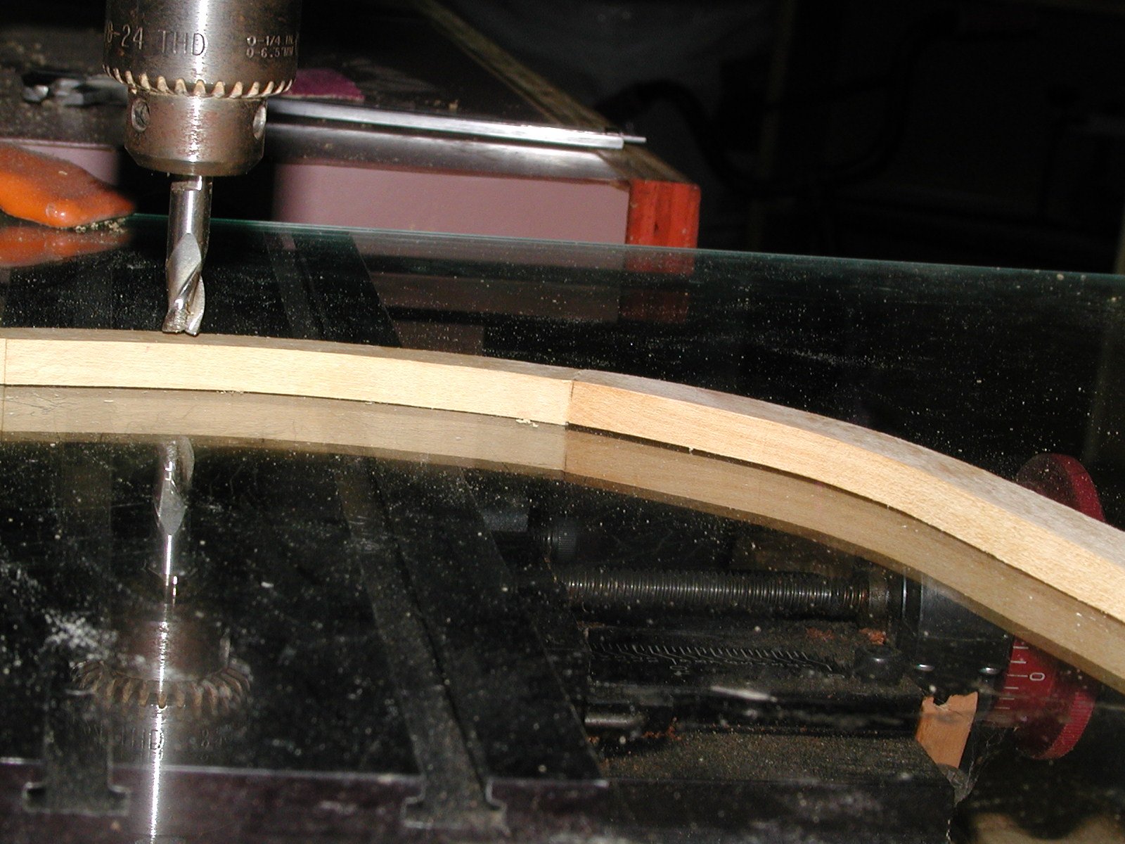
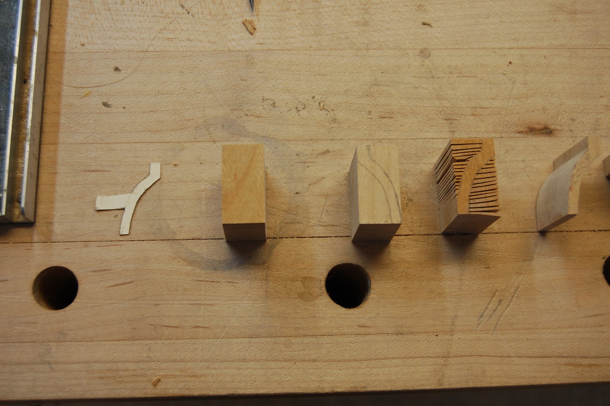
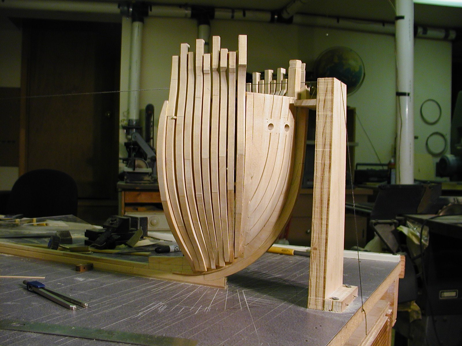
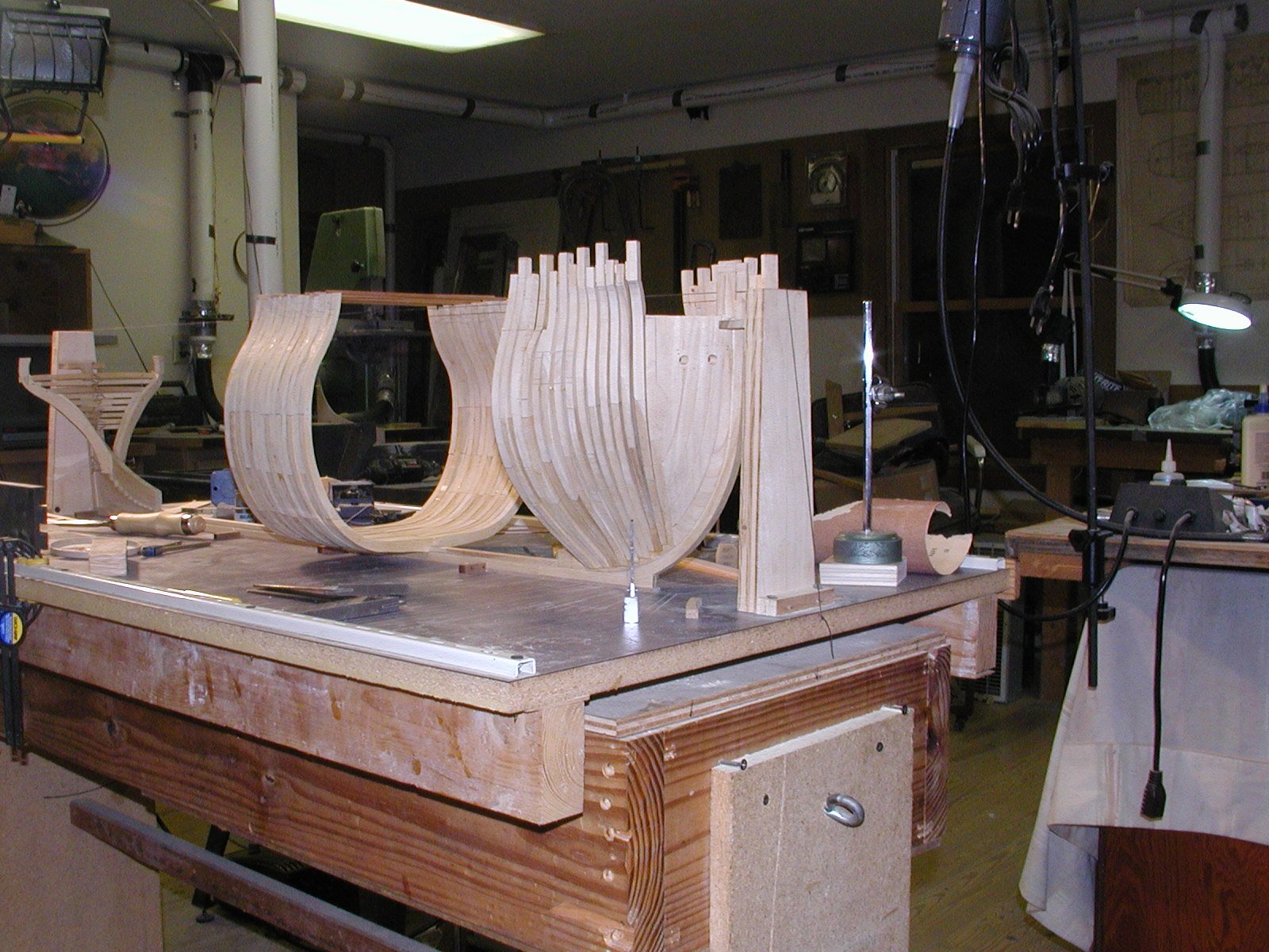
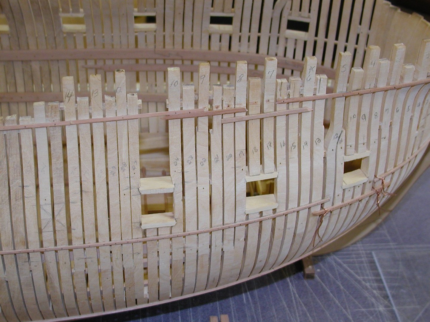
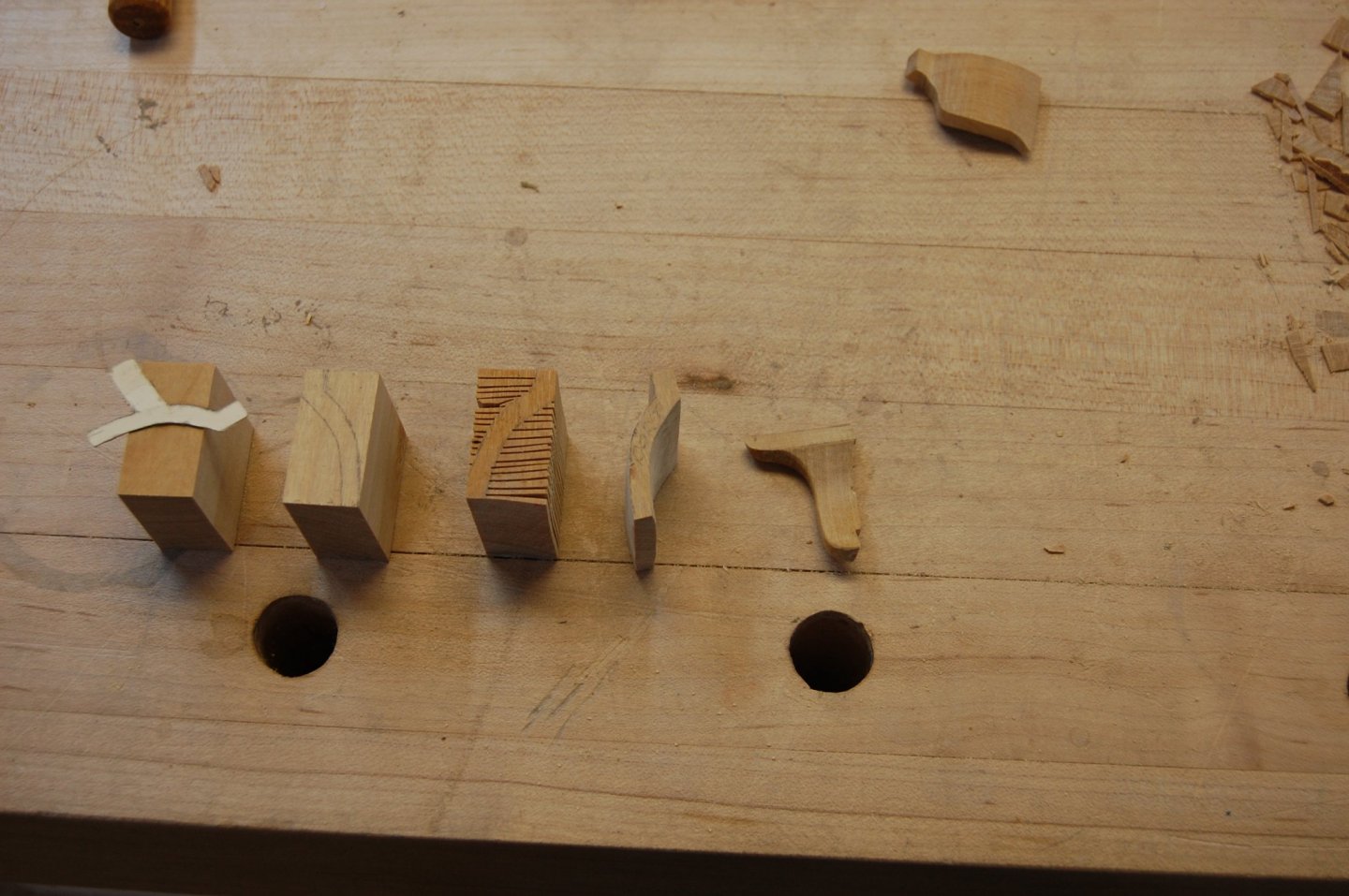
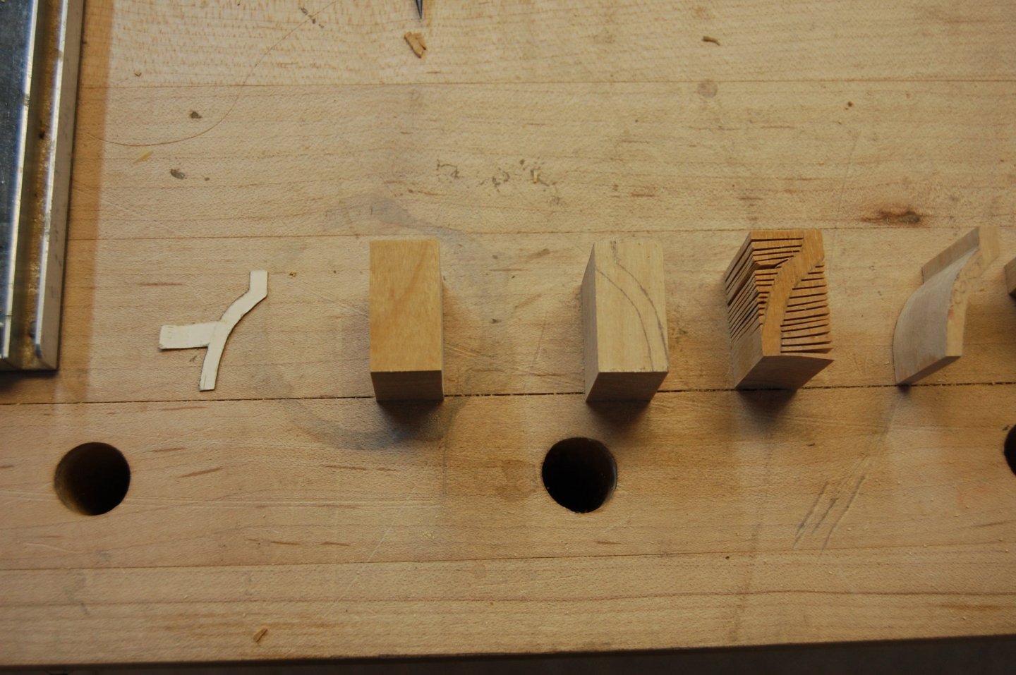
Hi Alan. When I was building my frames up for Alfred/Montagu I made all the pieces of that frame a little over size because of the parts being off set. Am not sure if you have a mill but I milled the pieces that were needed to be reduced in thickness, much as you show above, which had spacer's some times underneith to help keep every thing level. Those spacer's were glue to one side or the other with rubber cement and once ever thing was milled they could be removed and the cement rubbed off. I increased the size of my table by clamping a piece of temper glass to support the whole frame. Cast timber's were made thicker and then milled down with the help of thicker spacer's. You can see the cast timber in the last photo label number 5 at the top.

-
Hi Danial. Just to let you know good sir I have a very high respect for your skill and a out standing build that show's a very very high skill of work and understanding of your build. If i was a judge in a show of model's, I would give you the gold, silver and bronze medal's. You would deserve every one of them. Please keep up the outstanding build. Gary
-
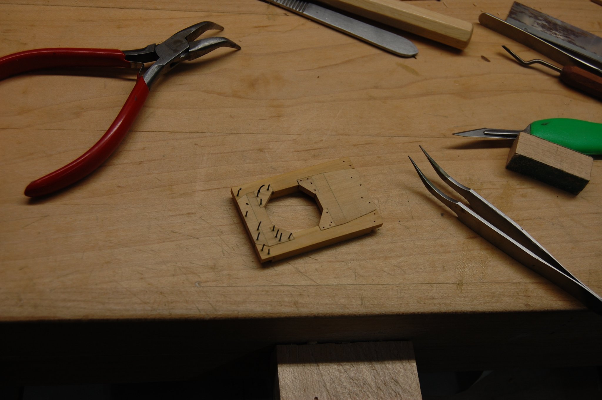
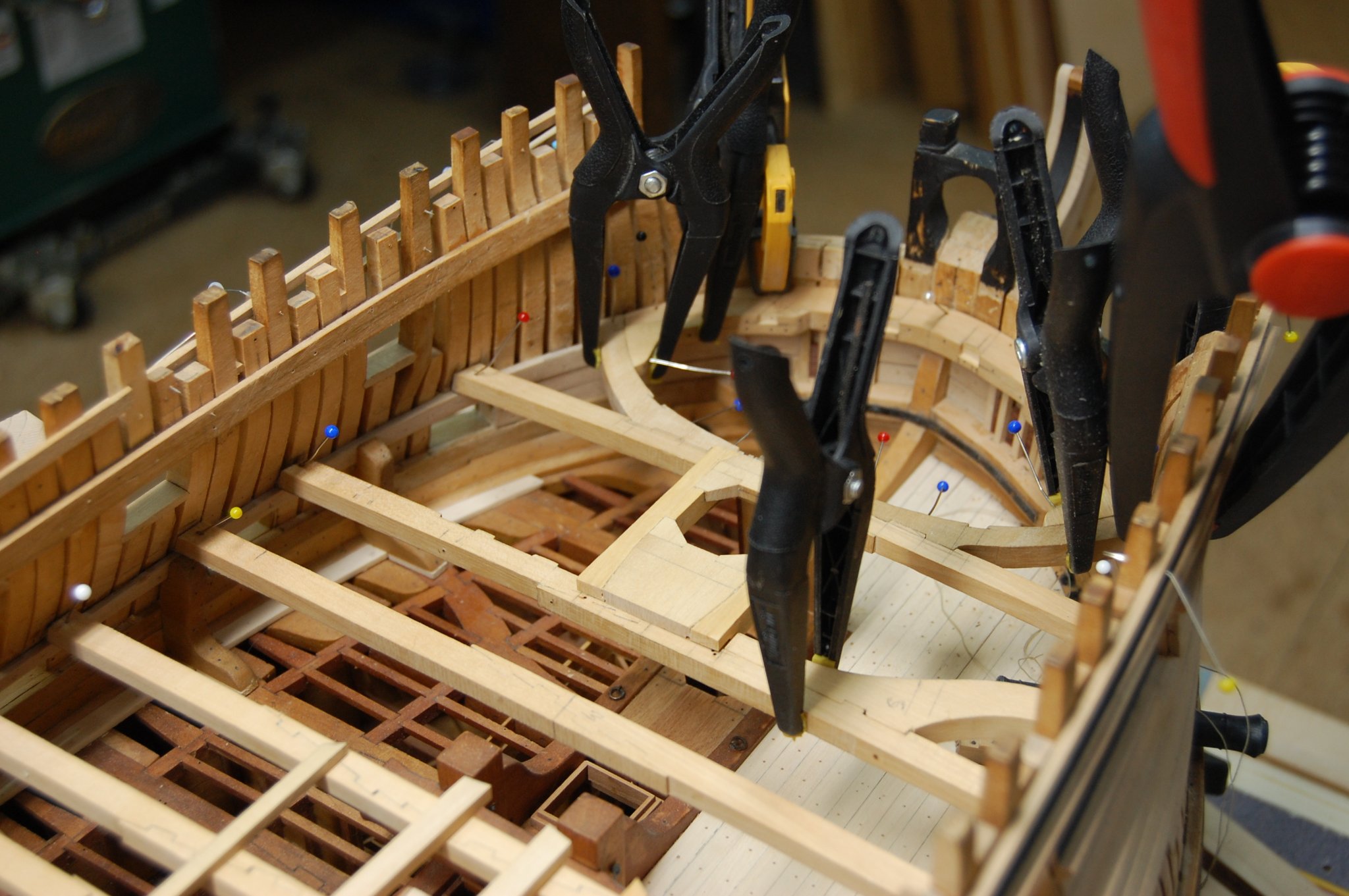
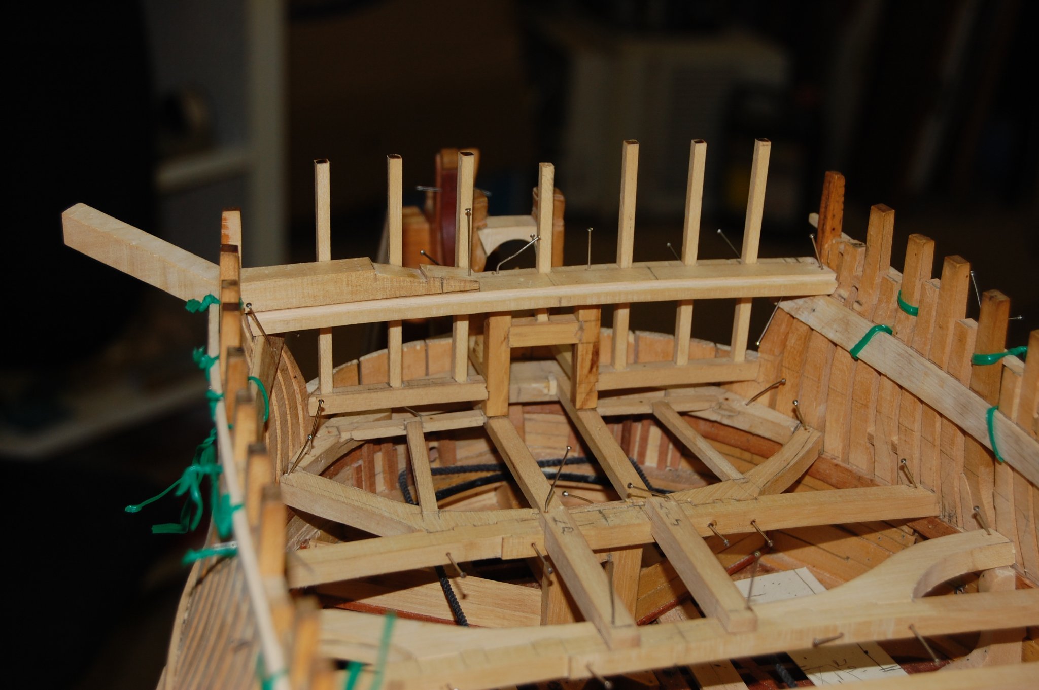
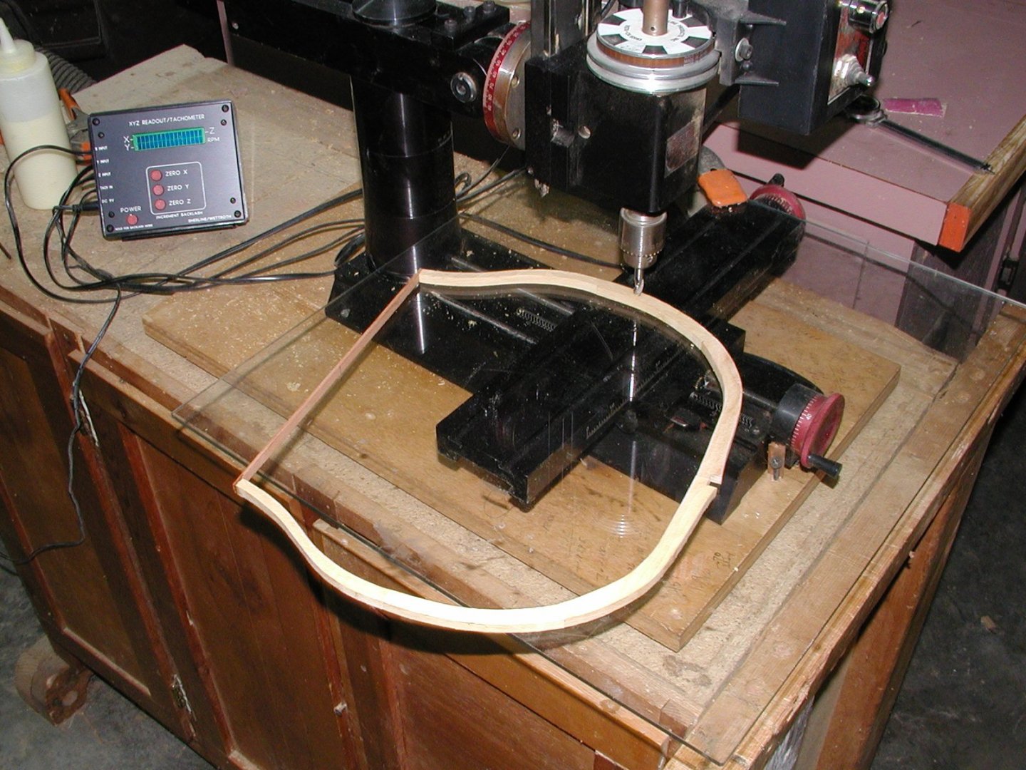
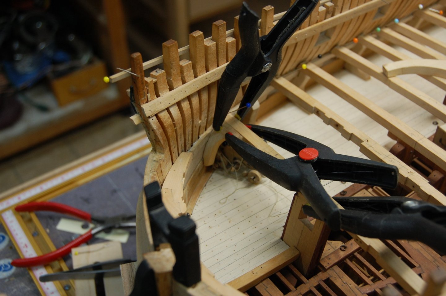
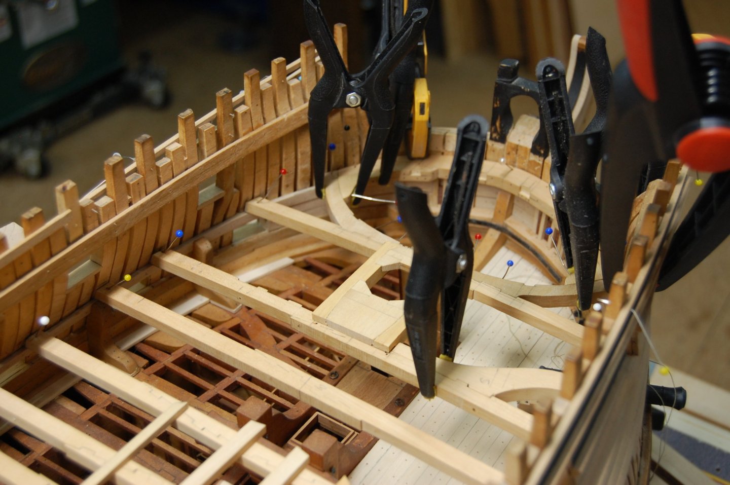
Hello every one. Here is a small update on my build showing the stages that making a cast knee goes through to become a cast knee for my build. Also a few photos showing the fore mast partner on the upper gun deck beams.The photo also show's the bolts being installed and is made up of 10 piece's of wood. Hope you enjoy the photo's

- 835 replies
-
- 18
-

-
Mark I have to agree with druxey on the exhaust of the stove and on the sheaves and or standards I do believe you would be ok if you added them or didn't. I have gone through my plans and some show the breast work knees and some that don't. The same thing with models some have them others do not. I think that from a different point of view having those knees would help those items to resist the stress of the rigging and being pulled loose from the deck itself. I also found three model's in the gallery that show them having those knees, the Ajax 1767, Hercule/Thunder 1760 and the Egmont 1768, along with the framed Bellona, so I do believe you are in good company. The number of sheaves in them, still looking for a answer on that one.
-
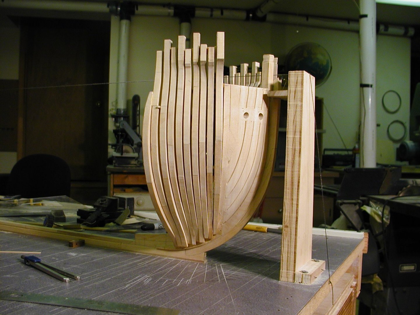
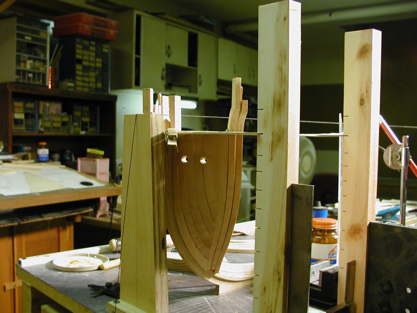
Hi Stuglo. You are doing a really great job but I would leave a little meat on the parts for finishing. Cutting to the line and leaving your self nothing to finish fairing the cant frames will give you a real head ack which I had to get the misses to buy me a couple of bottles of aspirin that helped when I was building Montague frames. You probably already know this but I like to sneak up on the line which help me, and to this day still sneak up on the line. Keeps me out of trouble. Seems I had to redo my cant's two or three times before I was happy with them and each time i got closer to what I was trying for. Here is a photo or two of the cant frames on my Montague. Keep up the good work and will be watching your build. Hope this is of some help to you. Gary

-
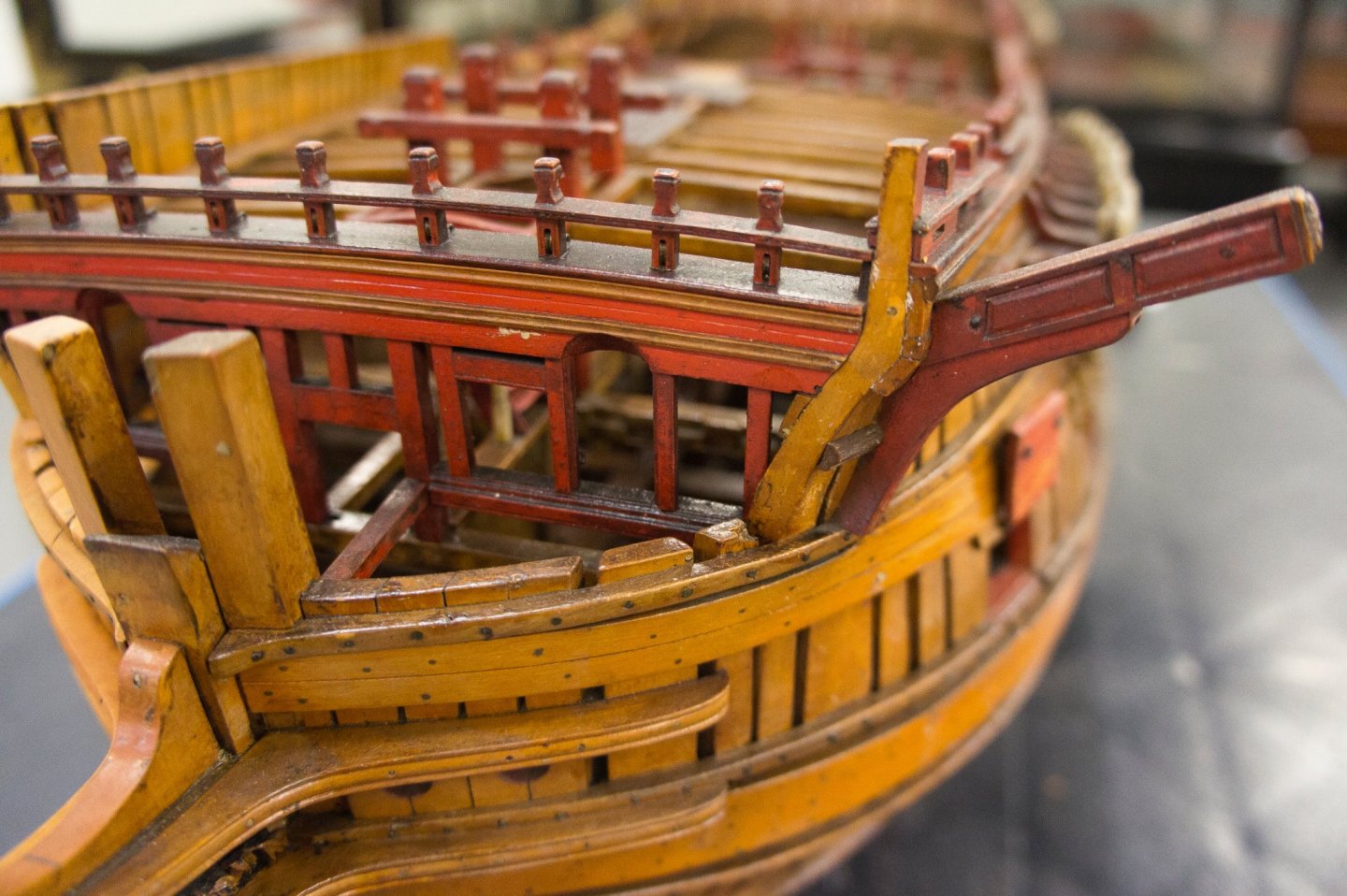
Mark I have a couple of question if you don't mind. From looking at the deck plan it looks like you have two large carlings underneith the stove. Is there a reason why it is showing two? After looking at the sheer plan, it shows that the pillars are on the side of that carling I mention above and shouldn't they be underneith that carling to support it? Some thing else I noticed Mark is I don't believe that they would have installed a pillar under the cat beam because of the collar beam set up. Here's a photo of my beak head and bellona that you shared that shows the heavy type of stantions that was used to hold the bow sprit in place along with supporting the cat beam. Gary

-
Alan those are nice and you may of been asked this before, are they hand made or CNC. Either way they are good looking. If CNC what machine are you using, Still have it in the back of my mind about getting one. Thanks. Gary
-
Hi Marsalv. You are really doing a outstanding job and enjoying your build. Thank you for sharing. Gary
- 589 replies
-
- 3
-
-
- le gros ventre
- cargo
- (and 1 more)
-
Hi Levmiller. Have you thought about hard Maple. It's a good looking wood and built Richard's frames from it. Its also good for full size furniture like a hobby desk and woodworkers bench. I prefere a light creamy type of wood such as para marfin and castillo box wood and use woods like pear for accent's. The model am building today have para marfin for the frames and really like the color of the wood. Came out like a honey looking color. Gary
-
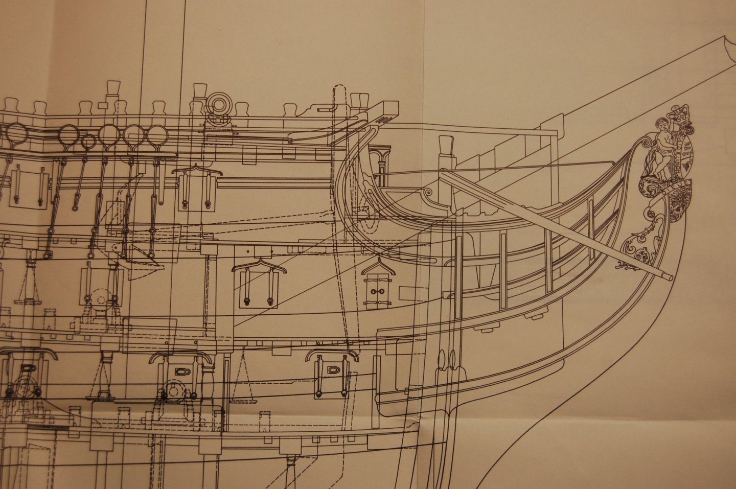
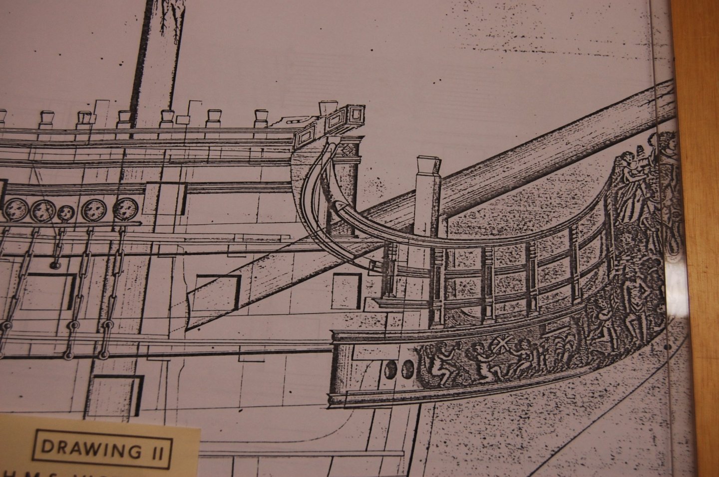
Hi Siggi. I saw that sir but it seems to only talk about that part of the deck behind the step it self. Behind the step on the upper deck was the fore mast partner which was the heavy type and at the gun deck you had the standard from the bit pins and in front of the step the standard from the stem to help strength the front of it on the forward side. Thing is it doesn't say any thing about in front of the step at the upper deck. I do think that those carlings that I have installed on Montague may of been supported by the messenger roller's. Goodwin shows them on page 178 and gives a time line of 1790 which is 10 years after Montagea, so could she have had them in her time, and am leaning to the side of she did. Hoping some one will set me straight on this one. I did find some thing on a Victory plan in Arthur Bugler book vol 2, which is the plans that show some thing around the bowsprit but at the moment unsure of what that could be. Another one is what the Victory was post of looked like when she was built, One item to noticed is that the plan, I believe I got from the danish museum, doesn't show her as having the small beakhead platform but just the upper deck planking going from the inside to the out side., and that one is for another day. Thank you Siggi and others for their in put and would of been a lot less fun with out those inputs.
-
Thank Alan and Mark. Alan I did the same I had some pictures of the walk through and as you say they are awol. Maybe some one some were has a set of those area's. Mark those delicate little diagonal pieces may have been installed to help support the heavy partner planking. My reason is that the hole in this was cut in a circle and you problem had the end of some of the planks sitting on those pieces. At the moment Mark am looking for answer's to you question but its a little on the slow side. Has far as the forward part of this opening I have to agree with Siggi and the most forward part of the hole is underneath the collar beam and my earlier build shows what and how this may of looked under the collar beam that I showed in a early photo. Plans show that beam, but not the stanchions. Mark you show pillars underneath the forecastle beams is there a plan that shows this? So far I have not found any thing that says there was but will look at a couple of items that may agree with that. Mark I looked at a couple of contract's that talk about pillars underneath the quarter deck and forecastle but as far as the forecastle it only mention iron ones around the stove. Gary
-
Hi Alan and Mark. fore give me guys am still trying to come up with answer for your post but in the mean time does any one have any photos showing the space under neith and on top of the upper deck of the Victory were the bowsprit comes through the deck and also were it come out of the small deck of the beakhead deck? Am trying to figure out how the space around and below was filled in. I know that it is a different time for how Victory is done today but it may help give me clues as to how just maybe it was done then. Thank you and will be back to answer on the upper post. Gary