HOLIDAY DONATION DRIVE - SUPPORT MSW - DO YOUR PART TO KEEP THIS GREAT FORUM GOING! (Only 20 donations so far - C'mon guys!)
×


garyshipwright
-
Posts
927 -
Joined
-
Last visited
Content Type
Profiles
Forums
Gallery
Events
Everything posted by garyshipwright
-
 Thanks Hubac's that means a lot coming to some one with very red cheeks. You know am going to have to work even harder to come up to that bar that you have set high. Thank you again. Wonder were I can get a taller ladder. TAXI, Lowes please. 😭 Gary
 -
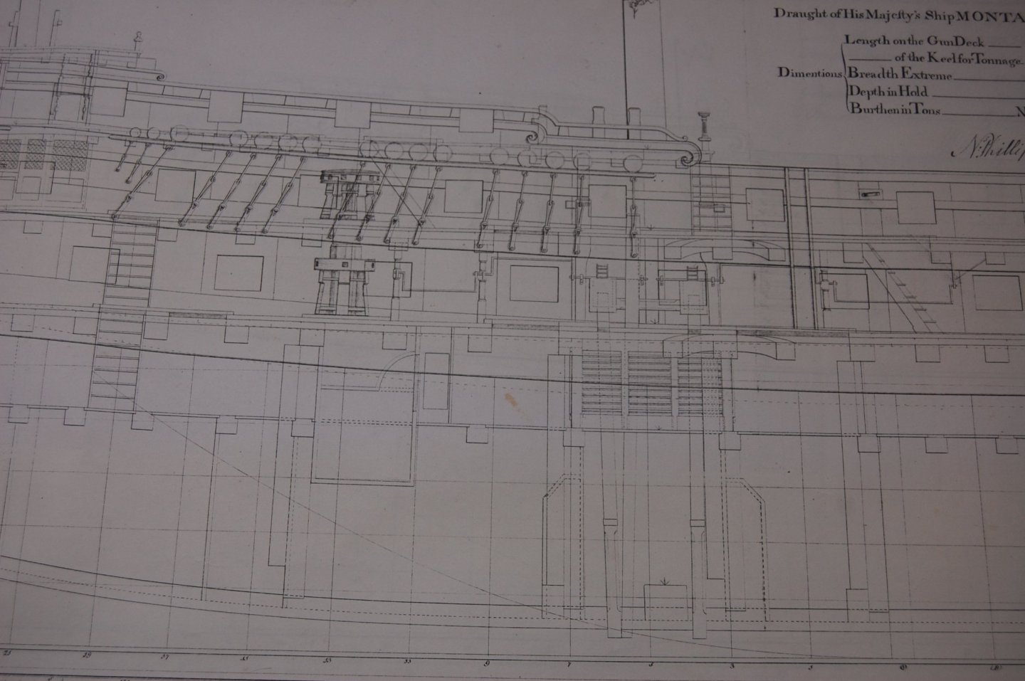
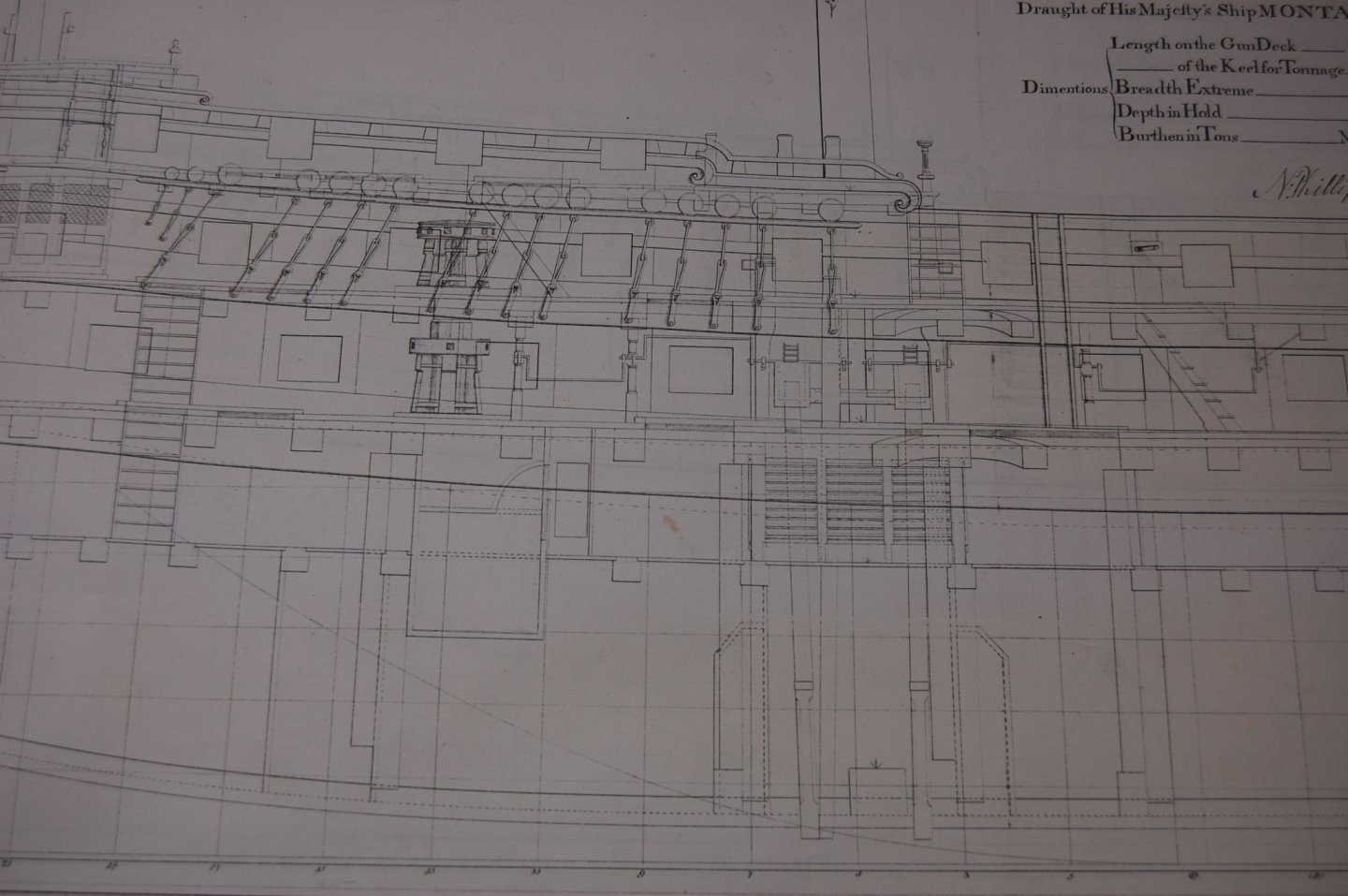
She does have some nice detail druxey but some thing else I noticed is the hand pump which in front of the aft chain pump and goes up to the upper deck. Alfred didn't have that detail and read some of them had those hand pumps and others didn't. Since Alfred doesn't show this and Montuga does, does not mean that Alfred had one? Another one of those question that I have been looking for a answer, but yet to find one. Well seems that question on Montuga answer that but still very interested in a answer if there is one. Maybe a best guess. 😭 Gary
-
Outstanding Johann, it so nice to wake up seeing your outstanding work. Thank you Gary
-
Hi Giampiero. Nice build sir. Looking good especially at the scale your building. Your Alfred doesn't look to bad either. Thank you for sharing with us. Gary
-
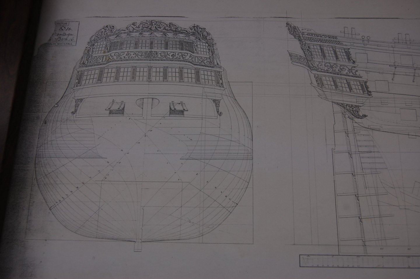
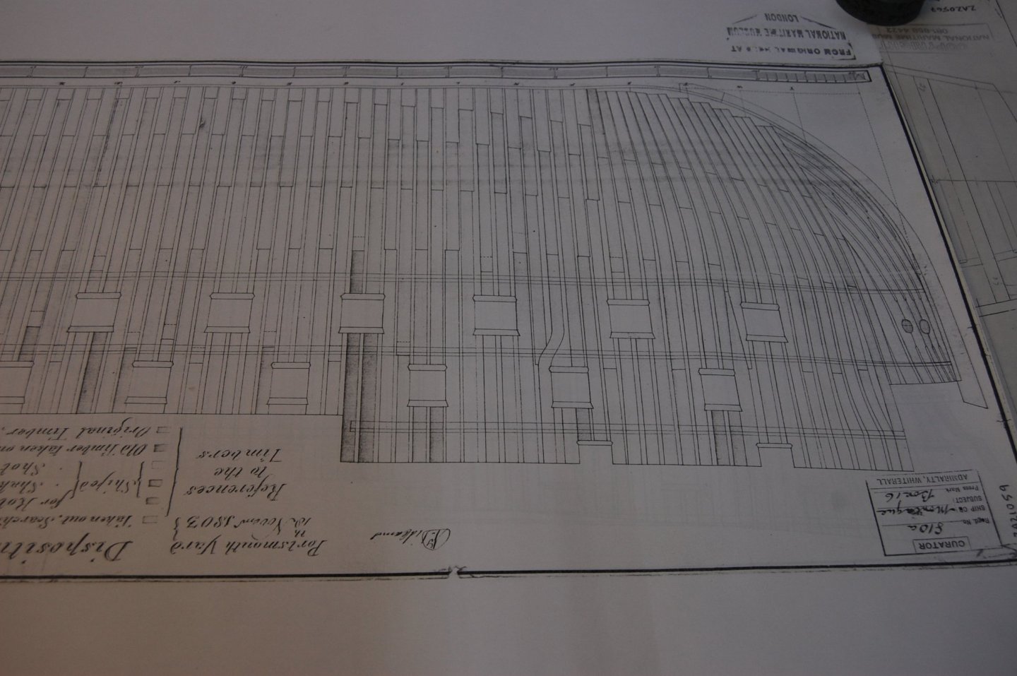
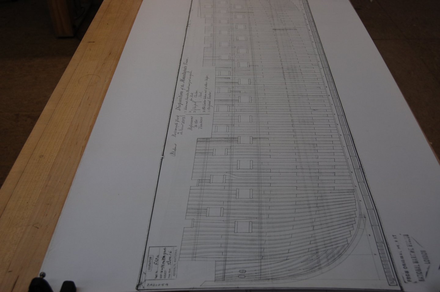
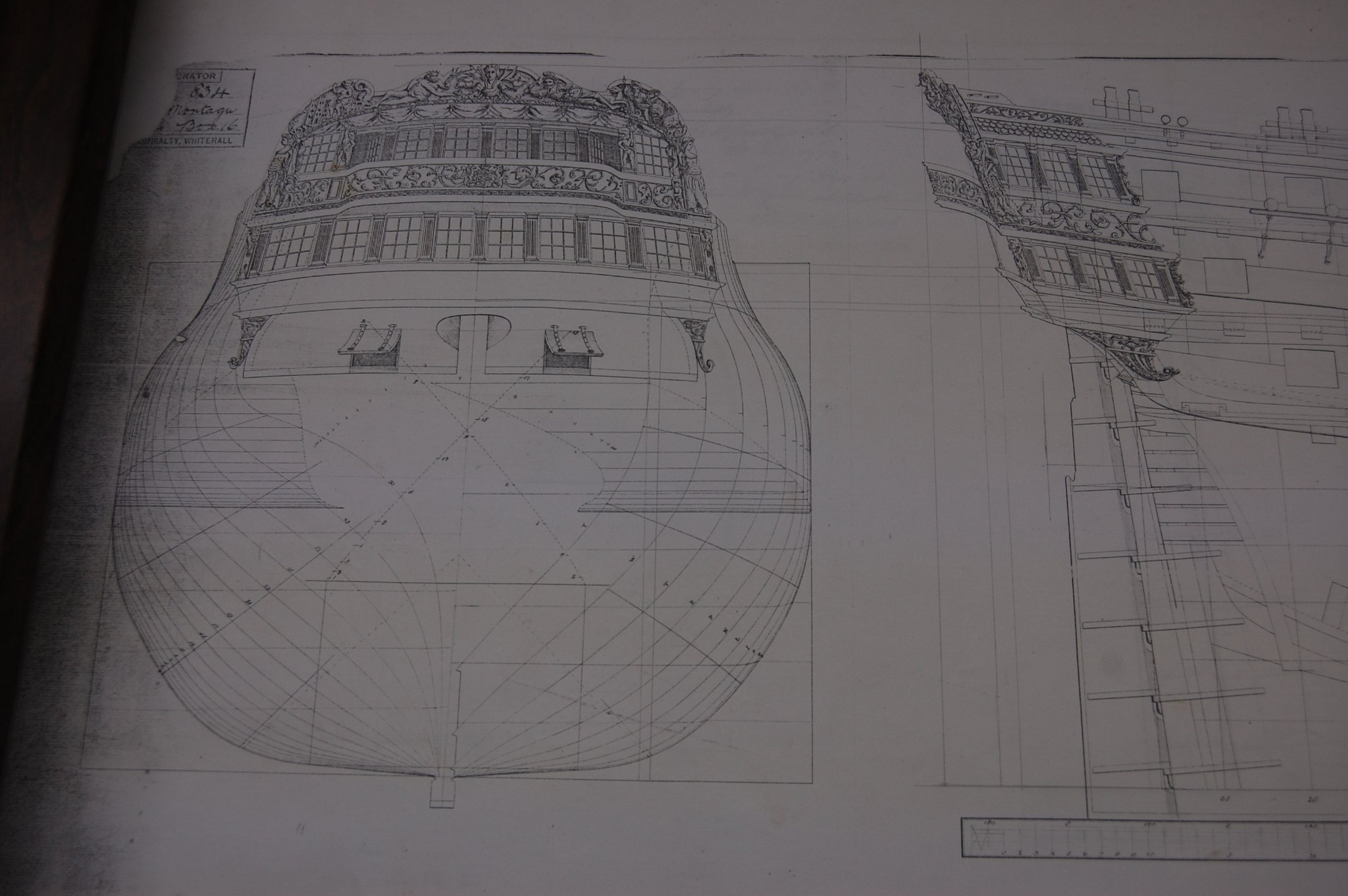
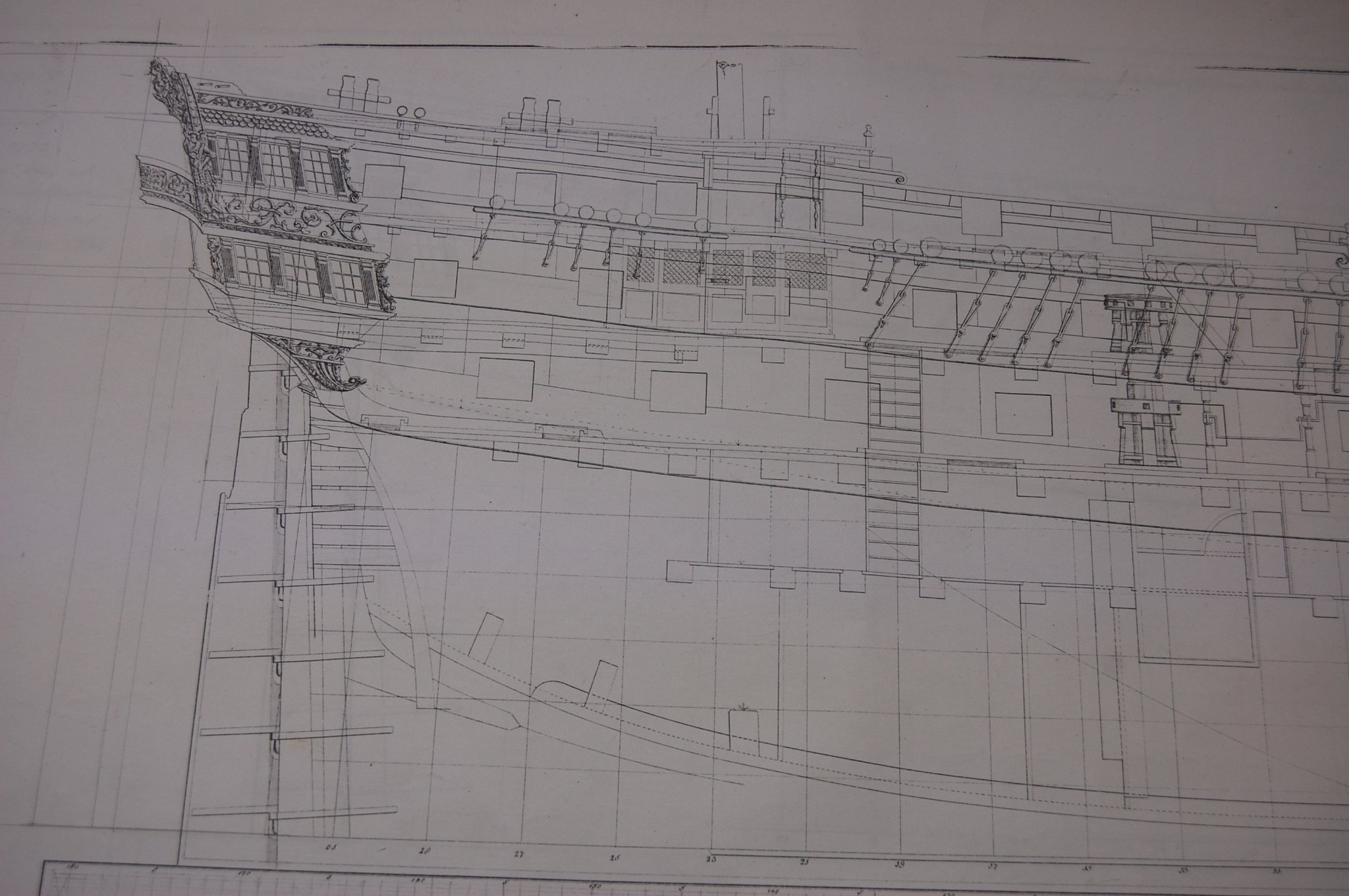
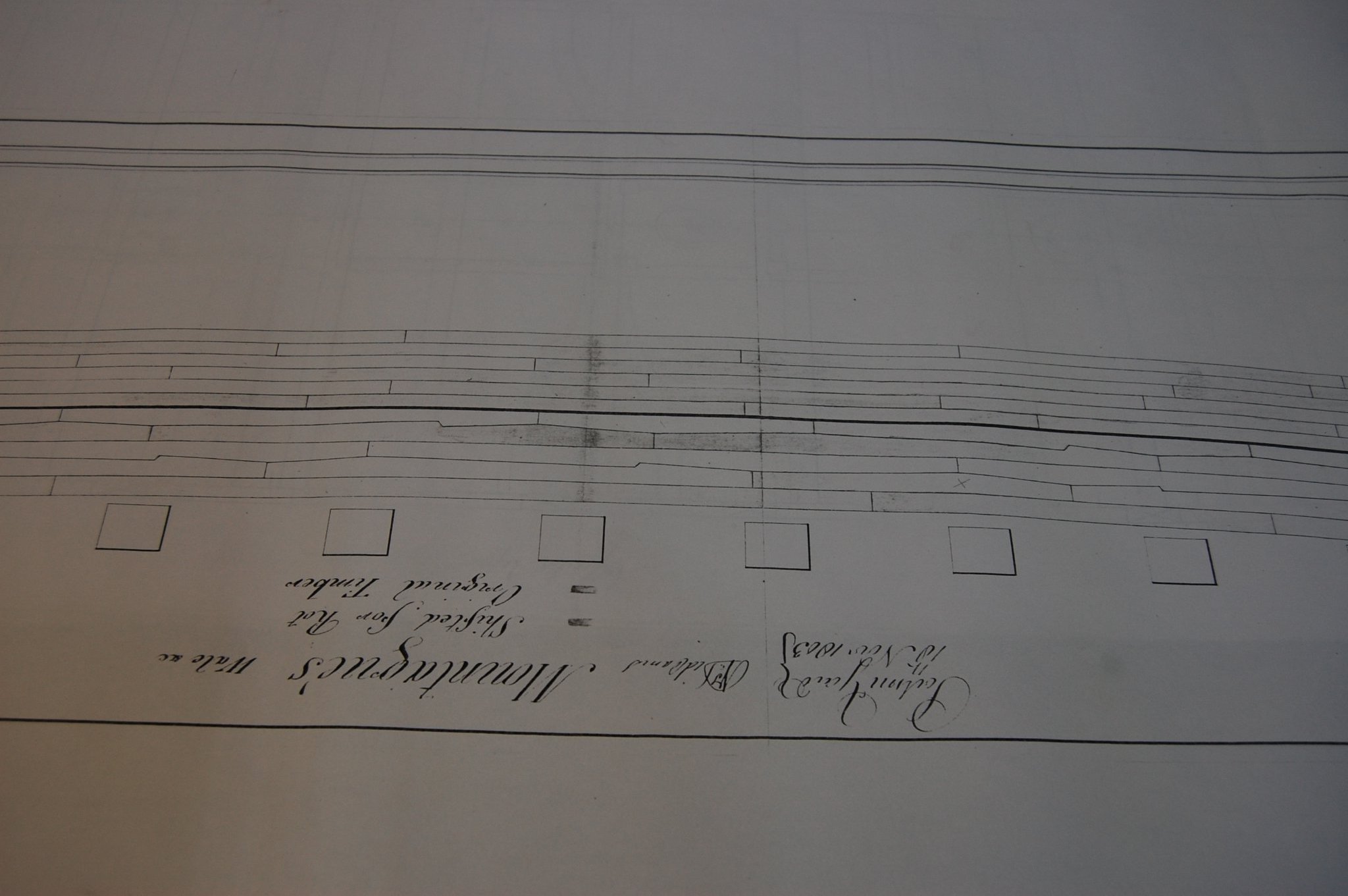
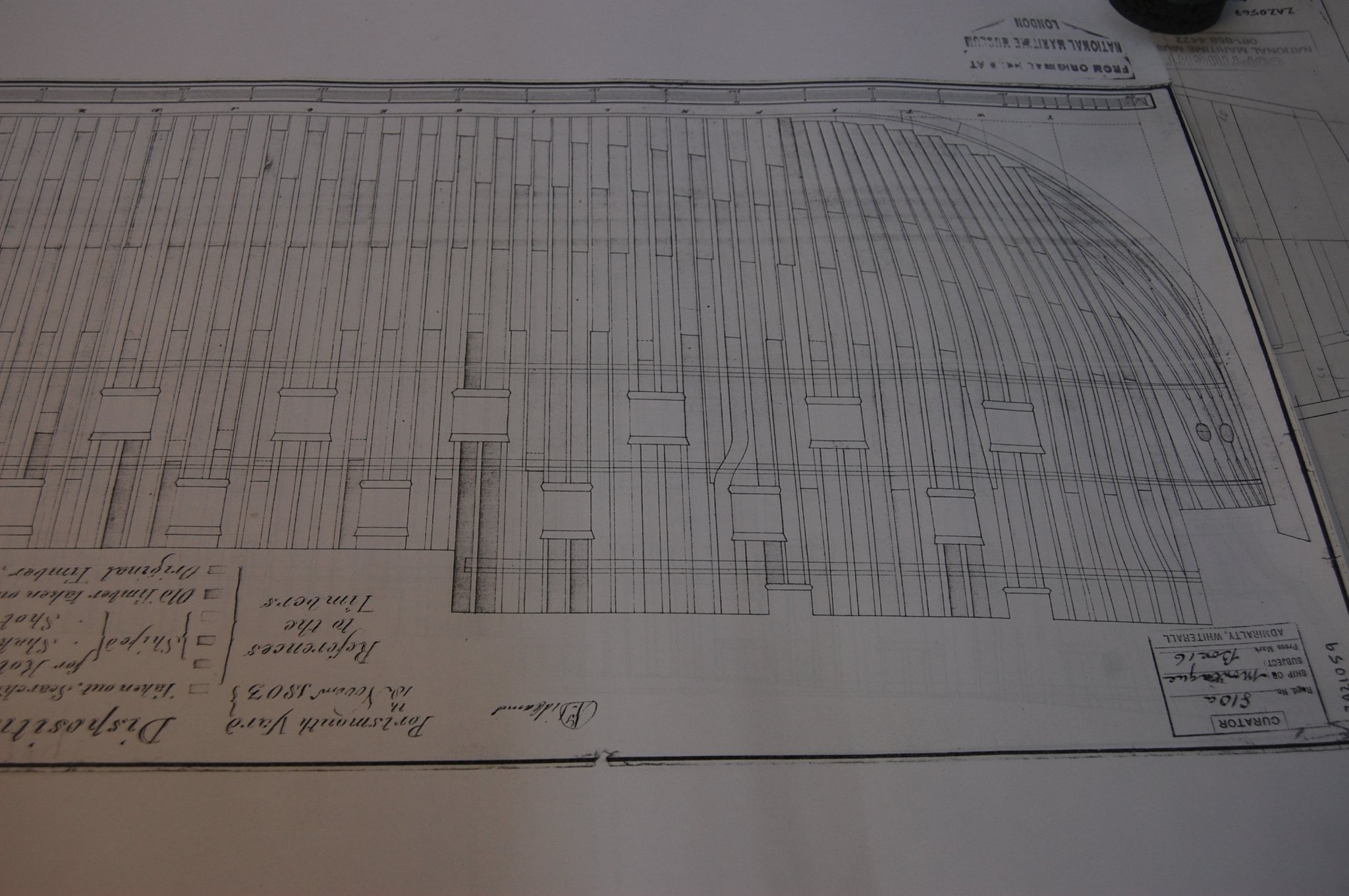
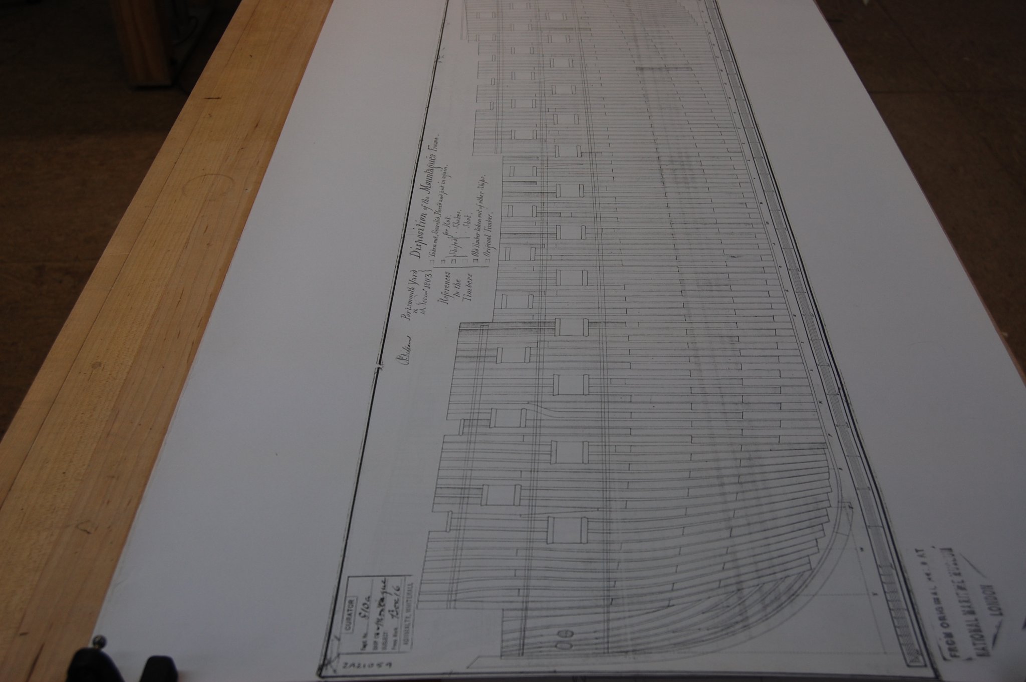
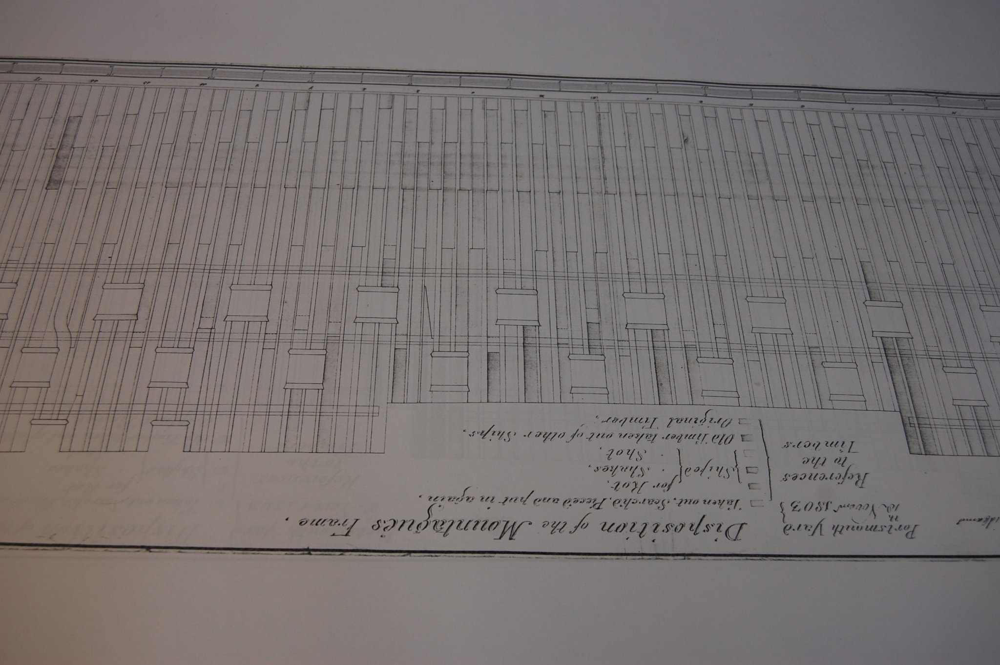
Thanks Mark she is good looking. While going over the stern of her I noticed that the bottom out side windows are larger and thought, well wonder if the increase the width of the upper counter and after looking and comparing the two, the outside pieces are not as wide as what's on Alfred allowing them to build bigger windows. Some thing else I took a hard close look at was the framing of the two and it seems they was framed with the same framing plan which I think was the Alfred plan. I did find a couple of cast top timber's that was on Montagu but this framing plan is when she had a large rebuild in 1803, so not sure if they were there before or after. The plans are black and white so it makes it just a little on the hard side.
-
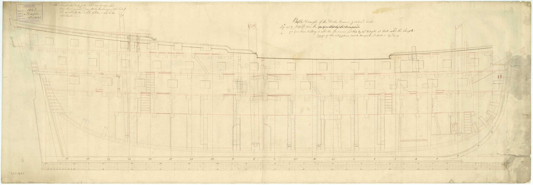
Your very welcome Mark. You are right and there isn't any pillars that will interfere with the tiller but there is one that goes between the end of the tiller and the beam on the back side of the mizzen mast. I just got done looking at the Dragon/Bellona Profile inboard works, you should be able to fit one more pillar under the beam were the tiller ends.I have the same set up with one behind the mizzen mast itself. The one forward of the forward bit can sat on top of the gun deck beam and because it goes underneith and hold's up the stove carling it will not be right underneith the upper deck beam, but it will still support it. If you want I can send you a couple of plans but you can see the same thing going on with the Glory I did send you one plan of the Temple of 1757 that shows the same pillar setting in front of the end of the tiller..

-
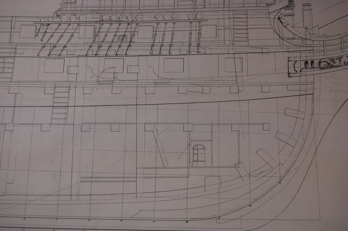
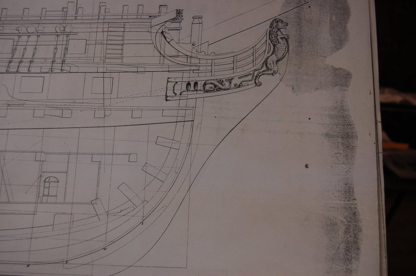
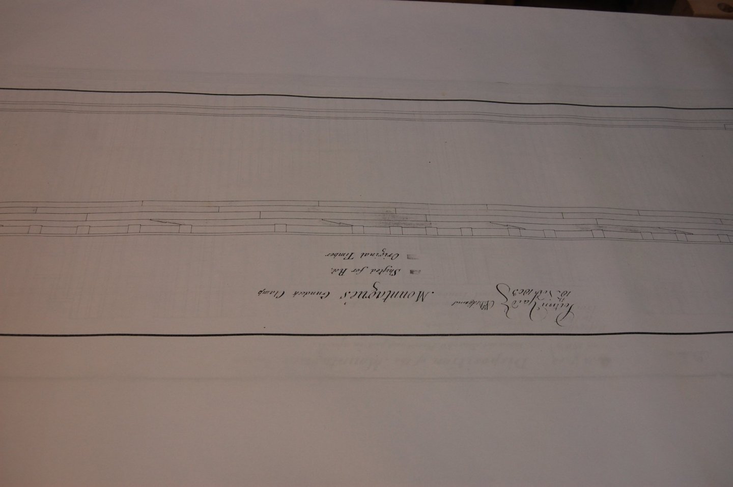
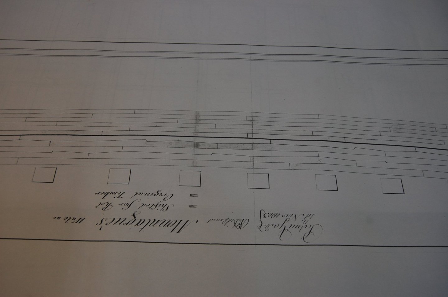
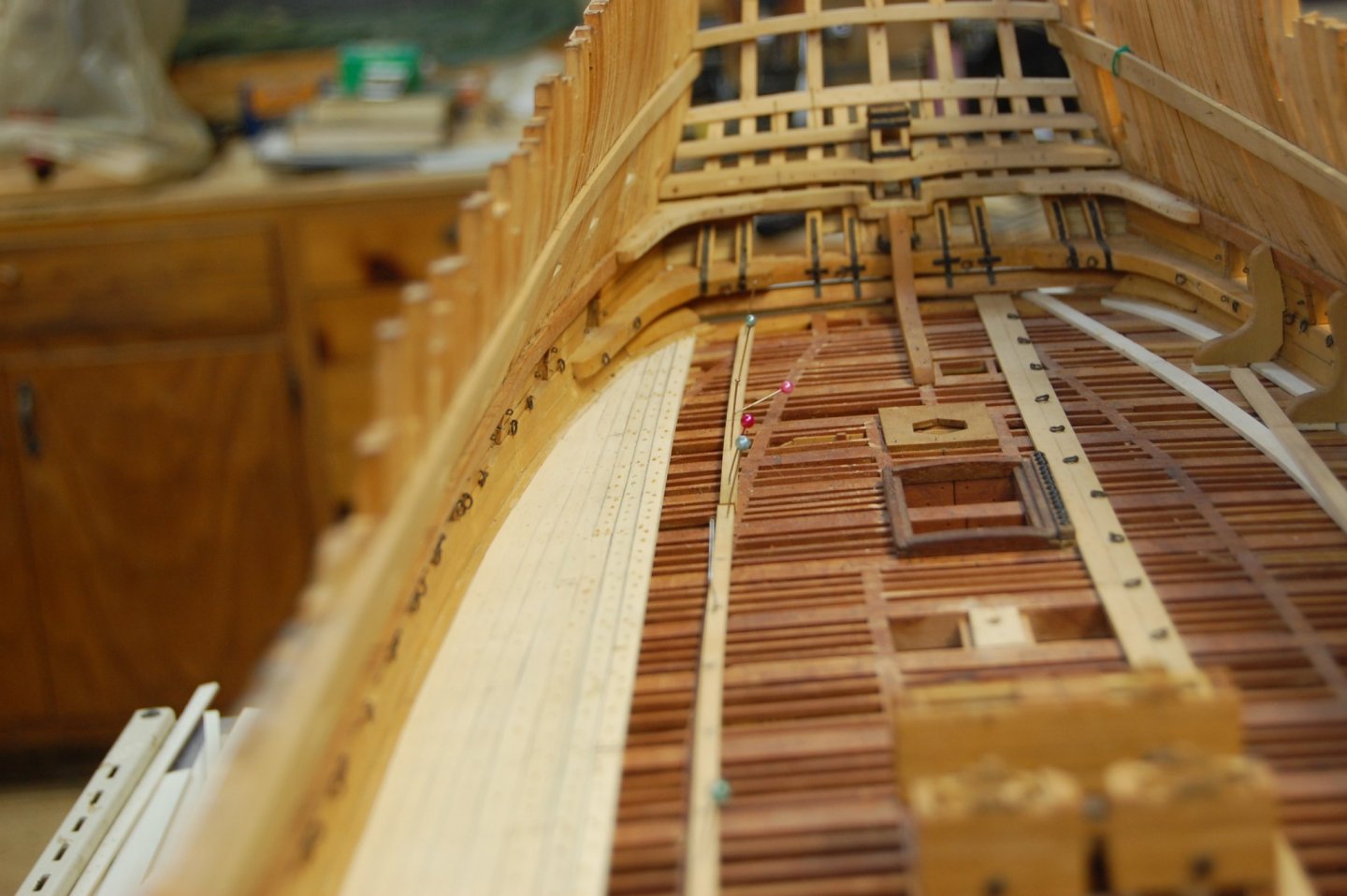
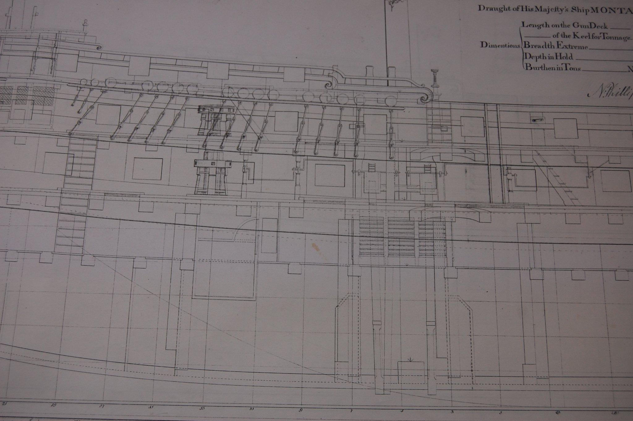
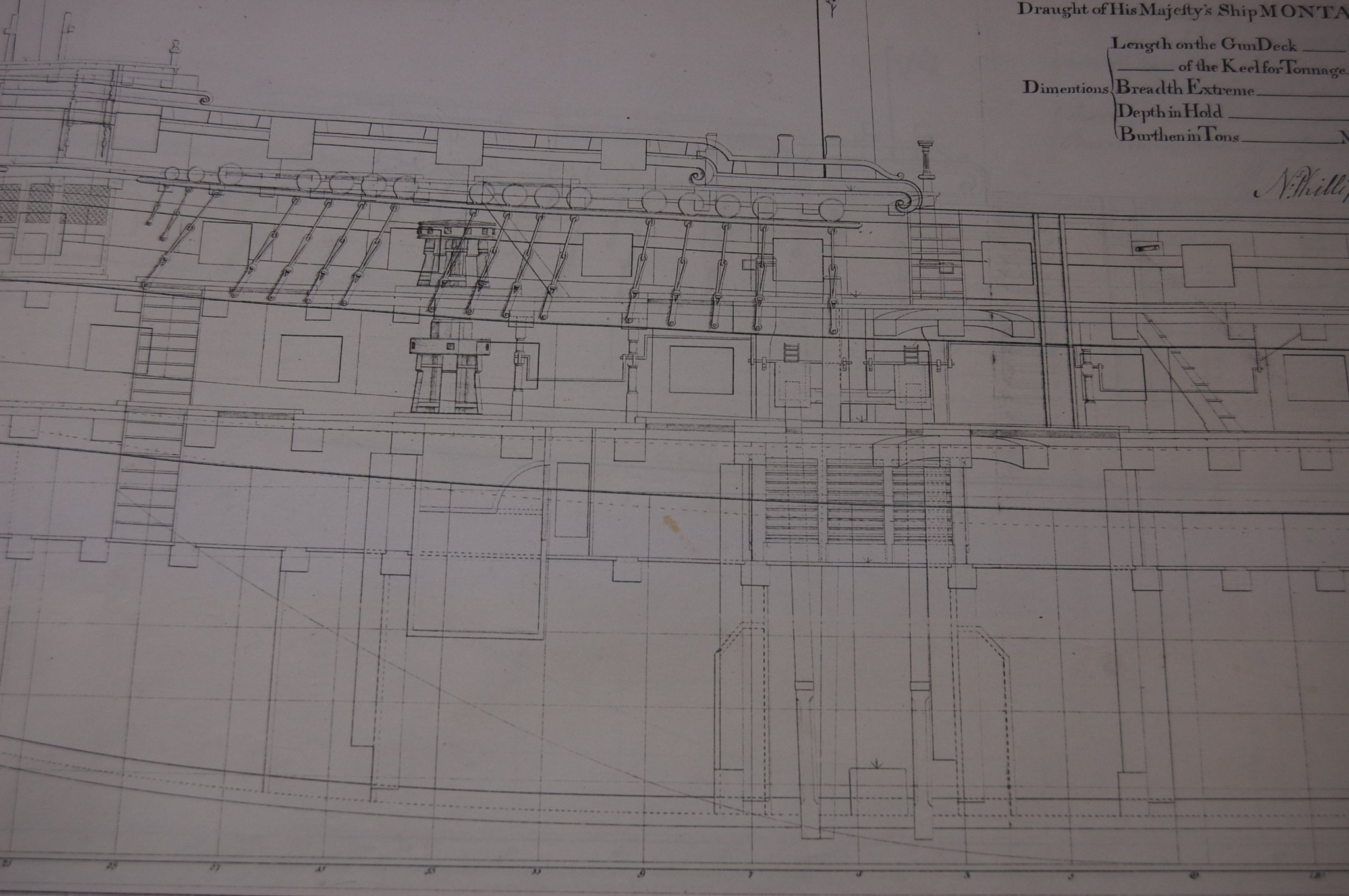
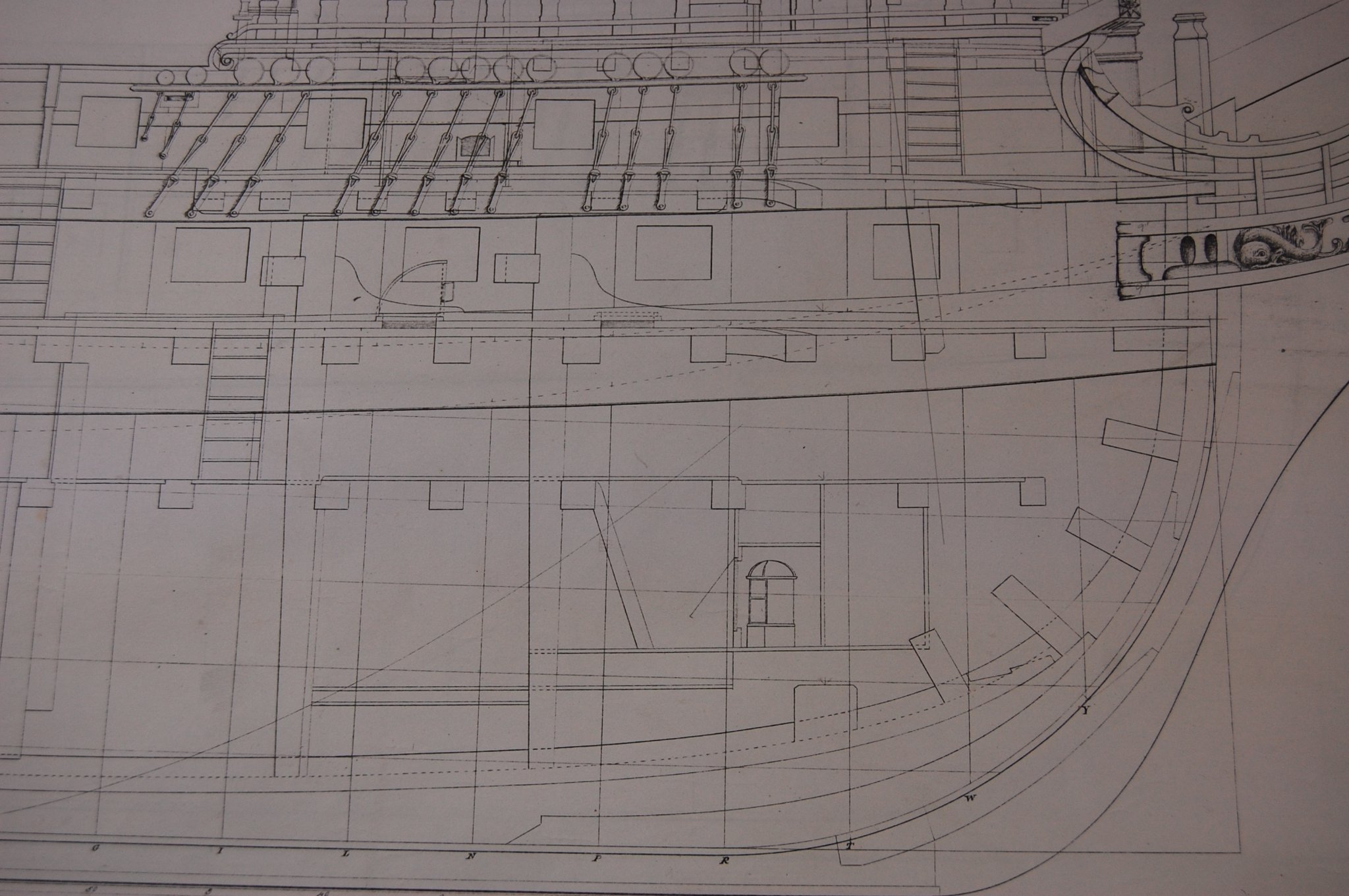
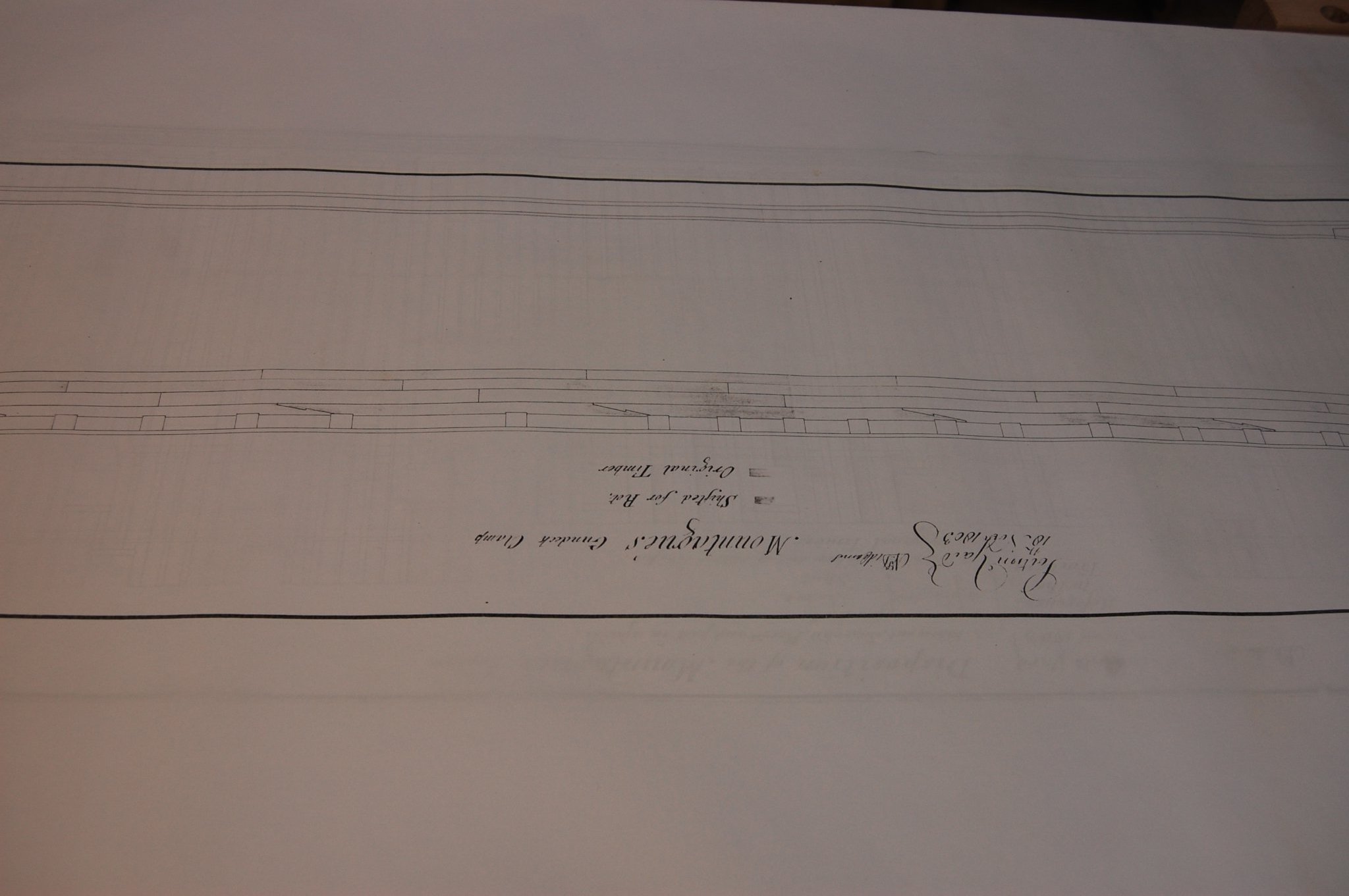
Well I am not sure if I should put the photo's here or at the beginning and probably just do both. Just to give you some info on the plans Montagu was built at Chatham launch and copper in 1779. Some of the plans show her Large repair in 1803 so figuring out how she was framed and planked when she was built.For some reason some of the photos turn them self's up side down and if one of the mod's can help me fix that I would be most thankful Gary


-
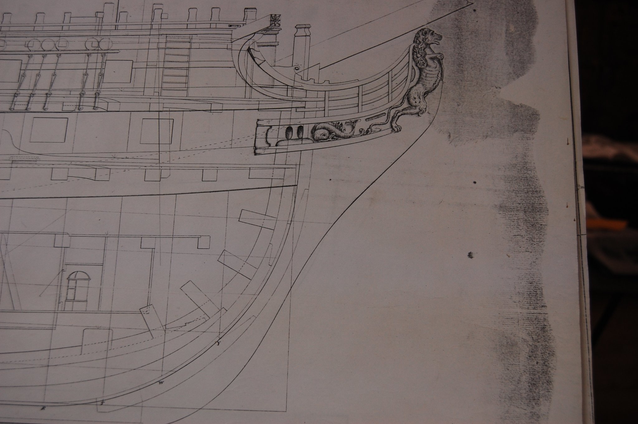
Hi Christian. If you go to the first page of the log, maybe the second post I made, you should see what the decoration of her stern and bow. I will put up Montague photo's of her sheer for you as soon as I have a cup of coffee and wake up good sir. If you want I can also PM them to you along with putting them up on the log. Gary
-
Hi Mark. If you go to page one in the log I put Montague history there for other's to read and probably need to add Montague plans there. I did add photo's of her stern and bow. If your interested in what the rest of her looked like let me know and will put some of her full sheer plan up. Montague came after Alfred by a year and yes there was a major differences in the decoration. Both of them was built from the same water lines as far as what I have research on the plans them self. As far as the decoration goes, since I have not reach that point they should not be to hard to do, just have to figure out what is what. if I was further along with the stern and bow I probably would not have done the change. I take some photos to show you the carvings .I have been using her plan's along with Alfred and it does seem that there are more detail plans of her then Alfred. Another thing is that Montague is rare compared to Alfred which also may of had some thing to do with the change. Also another thing that help my decision with the change was the Swan books were they build the class plan and by changing the carvings they came up with a different swan ship. There may be a few more things that might be different and will cross that path when I get to it. That good sir is my story and am sticking to it. 😊 Thank you for asking. Gary
-
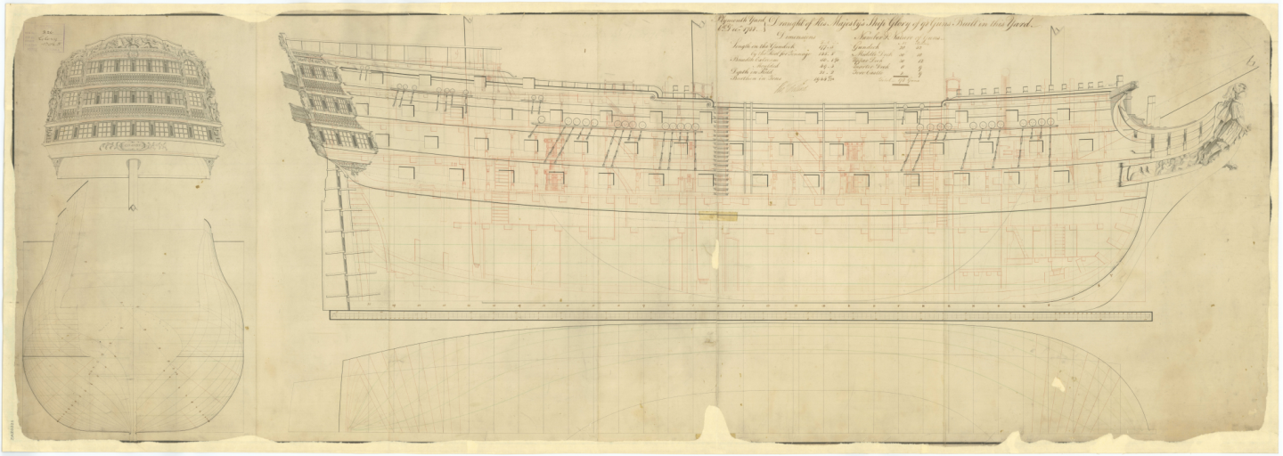
Mark if you look in Lavery book on the Bellona, on page 27 you will see the lower deck of the ajax of 1767 which shows the layout of the pillars. It does seem a couple of them are missing but you can tell because of the color difference of the wood in those spot's when you look at it. There is also a mid section of a 74 that shows 6 pillars, three per side around the capstain. I don't think that bigger ships with only a 3 foot difference would have called for a double row but a single role untill something like the capstan/pump handles, changed the setting of them. My understanding, and can't remember were I read this, if they set one pillar on top of the one below it, it would help transmit the weight of the decks down to the keel/ keelson. I will do some more looking for something that just tell us were they were placed. you may be right on the rows so don't hold me to this. My reason is if you look at the Glory at the stove carling you will see the pillars under neith it sitting on the deck plank in the middle of the gun deck beam. We know this carling was in the middle of the upper deck beam which leads one to believe they are sitting in the middle. Also if you look at the forward capstain you can see that the capstain is shown behind the forward pillar which would tell me another pillar is on the other side. . To me it looks like most of the pillars are touching the dash line on the bottom of the beams which would be the middle of the beam I believe on the bottom of it. We also know that around the chain pump there is a row of pillar's on both sides. Just my thoughts. Gary
-
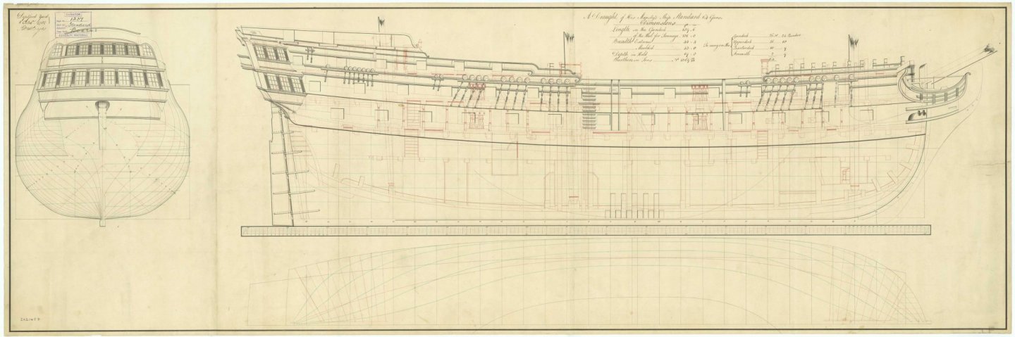
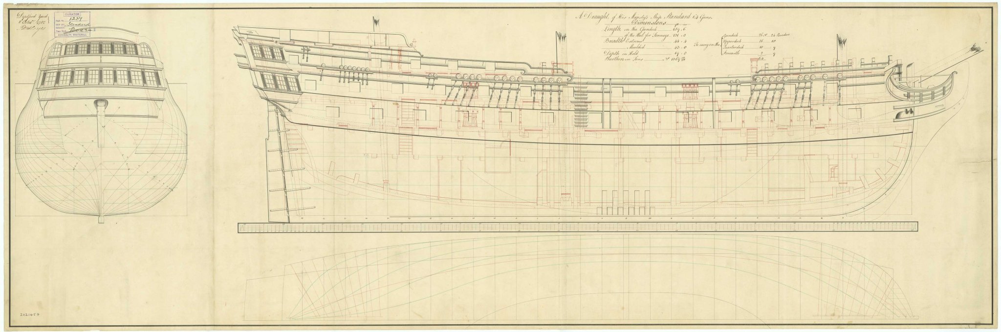
Mark here is a draught of the Glory of 98 guns showing what I believe is the way her pillars were laid out. On her gun deck and middle deck looks to have all her pillars and seems there is one on each side of the capstain on the fwd side. I know its not a 74 but at the moment its the best I can find. Hope it help's. I also added one of the 64 gun ship Standard. Gary
-
Thanks Alan, this may just come in handy. Gary
-
I remember those days accept we had to do it on a chalk board. Well I did get some play time in with my boats. 😊
-
Alan you forgot one, helmport. 😊😁😁😊. But it does make sense when you go looking up the term rudder hole which you can't find. Ok I go play with my toy boats now, in the bath tub 🤗
-
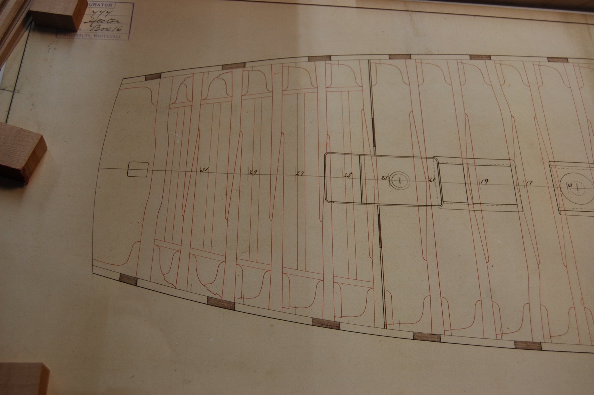
Hi Mark. After looking at your knees lay out at the last couple of beams of the upper deck I found out that fitting hanging knees in the last 3 or 4 beams that it was not possible for me and it was because of the knees that fit the helm port and wing transom. They are big knees which stuck out from the side, and would have may it just a little on the hard side fitting hanging knee's. It made of been the way I fitted them but can think of no other reason why Hector plan show's them that way. When you look at the plan of the Hector you will noticed that they used double lodging knees between the last few beams because of those transom, at least that is what comes to mind. Here is a photo of those knee's on Alfred that show those knee's. Any way it does give you some thing to think about when you get to this point. I looked in your log for those knee's on Bellona but doesn't look like you have added them yet. Just some hind sight for you. Gary
-
Hi Mark. I just checked some of the contracts I have and the one in 1755 gives the Hanging knee arm against the beam as 3 feet 7 inches long and the Lodging knee arm against the beam as 4 feet long. The contract of 1763 says the same thing accept the hanging knee arm is a inch shorter. They also say that the lower end of the hanging knee has to run down at least 6 inches past the upper edge of the spirketting. This is what am using as a base line for making mine on Alfred upper deck and doesn't seem to have changed much up to Steel's time and looks like it increased in only a inch or two.
-
Guys being that we are talking about the aft part the Dorsetshire had a different set up of those aft carlings so I take it that those half beams may of been shorter then the one's on Hector being she was built in 1757 right around the time of Bellona? Mark forgive me for talking about this on you log but figure it would be interesting to talk about. Gary
_RMG_J3114.thumb.png.b5e83574fbd3b69fd221f59cdf29f506.png)
-
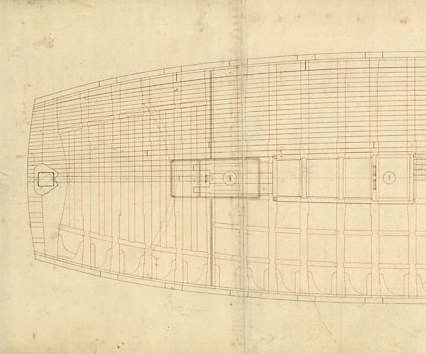
Hi Mark I don't think Siggi is talking about the half beams but the knees at the side being cut off at the ends. I think if Mark moves the carlings in closer to the middle line they would not need to be cut off at the ends. I up load a photo of aft part showing how this was set up. Its for a 74 but not sure which one.Also added one of Hector. Forgive me if you know this which am sure you do🙂 More for others to see what we are talking about then us old timers like my self.

-
Thanks guys learn something new ever day.
-
Thanks druxey, well it could be, am easy and won't be no augment from me.😁
-
Mark are you talking about the item below the tiller, am not sure what that item is but it could be. Gary
-
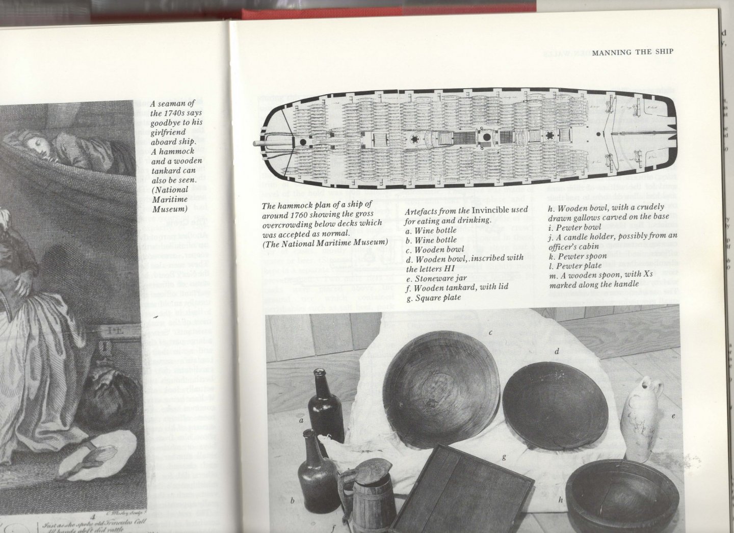
Mark here is a photo from Brian Lavery book Building the wooden Walls, The design and construction of the 74 gun ship Valiant and shows the tiller and ropes which seems to be the same as what's in Bellona. Says it comes from the NMM and gives a date of 1760.


_RMG_J3114.png.e23f23de7dd76d4871aaf16bf4d2f37c.png)