Hubac's Historian
-
Posts
3,306 -
Joined
-
Last visited
Content Type
Profiles
Forums
Gallery
Events
Everything posted by Hubac's Historian
-
 She is a CAPITAL ship, she is. Nice detail with the bowsprit shrouds!
- 324 replies
-
- 1
-

-
- Sovereign of the Seas
- Airfix
- (and 1 more)
-
Foot-ropes should absolutely be behind the sails. Whether they were even fully or partially present on French ships before the 1690s is a subject for debate.
- 1,508 replies
-
- 1
-
-
- Le Soleil Royal
- Heller
- (and 1 more)
-
Michael, is any of the model glued together at this stage?
- 324 replies
-
- 2
-
-
- Sovereign of the Seas
- Airfix
- (and 1 more)
-
Thank you, Michael! Agreed - the clarity of those images is pretty astounding!
- 2,699 replies
-
- 3
-
-
- heller
- soleil royal
- (and 9 more)
-
Brilliant lights, Michael, and very impressive how the whole stern came together.
-
That's a really nice touch to flesh-out the hancing ornaments on the inside of the bulwarks!
- 324 replies
-
- 2
-
-
- Sovereign of the Seas
- Airfix
- (and 1 more)
-
Hi Jake, You should consider opening a build-log of your own to introduce and discuss the project. As far as the Mayflower is concerned, she is so early in English naval architecture that no sort of contemporary plans exist. Whatever ornamentation she might have had would be minimal and completely conjectural through the modern lens. I think naval historians are happy enough to have an approximate idea of her hull form as a merchant ship.
-
That rings familiar, Gary - I think you’re right on Elbert. I appreciate your looking in, and happy Holidays to you as well.
- 2,699 replies
-
- 2
-
-
- heller
- soleil royal
- (and 9 more)
-
We are all somewhat dated, John. Model ship making is a dated-man’s activity.
- 2,699 replies
-
- 7
-

-
-
- heller
- soleil royal
- (and 9 more)
-
I’ll second that, and say also that your execution of the moulding work is off to a sterling start. This is going to be one of the more fascinating projects on the site as something familiar - the hull for L’Ambiteaux - transforms into something less understood: Le Fulminant. Whomever made the hull really did an excellent job. On a personal level, I would not be enthusiastic about investing all of the time, research and carving work on a project like this, if the underlying woodwork were in any way sloppy. This hull, most assuredly, is not that. It all looks to be a very harmonious collaboration of highly skilled makers.
-
Well, Bill, other modelers have been educating me along the way, and sometimes their suggestions are too compelling to ignore.
- 2,699 replies
-
- 2
-
-
- heller
- soleil royal
- (and 9 more)
-
Ian, if I have confidence in anyone, I have confidence in you. Your version will probably float, tack close to the wind, and keep the combined Anglo/Dutch R/C flotilla at bay. I’m excited to see what you do because I know it will be awesome AND innovative! Also, a very Merry Christmas to you!
- 2,699 replies
-
- 6
-
-

-
- heller
- soleil royal
- (and 9 more)
-
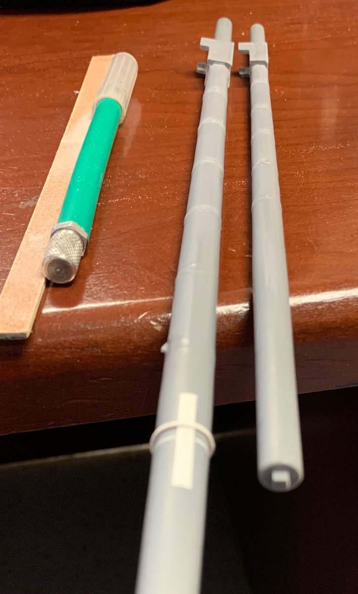
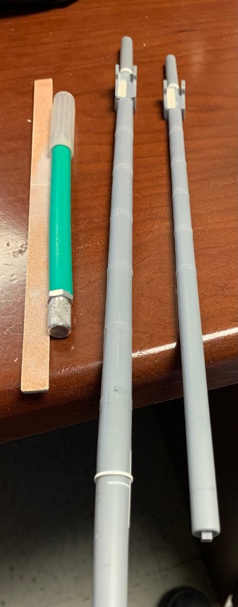
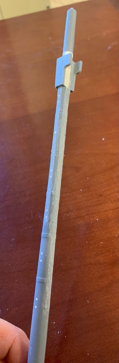
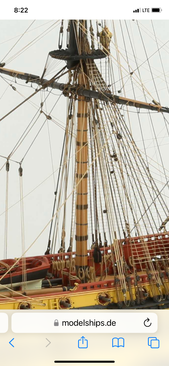
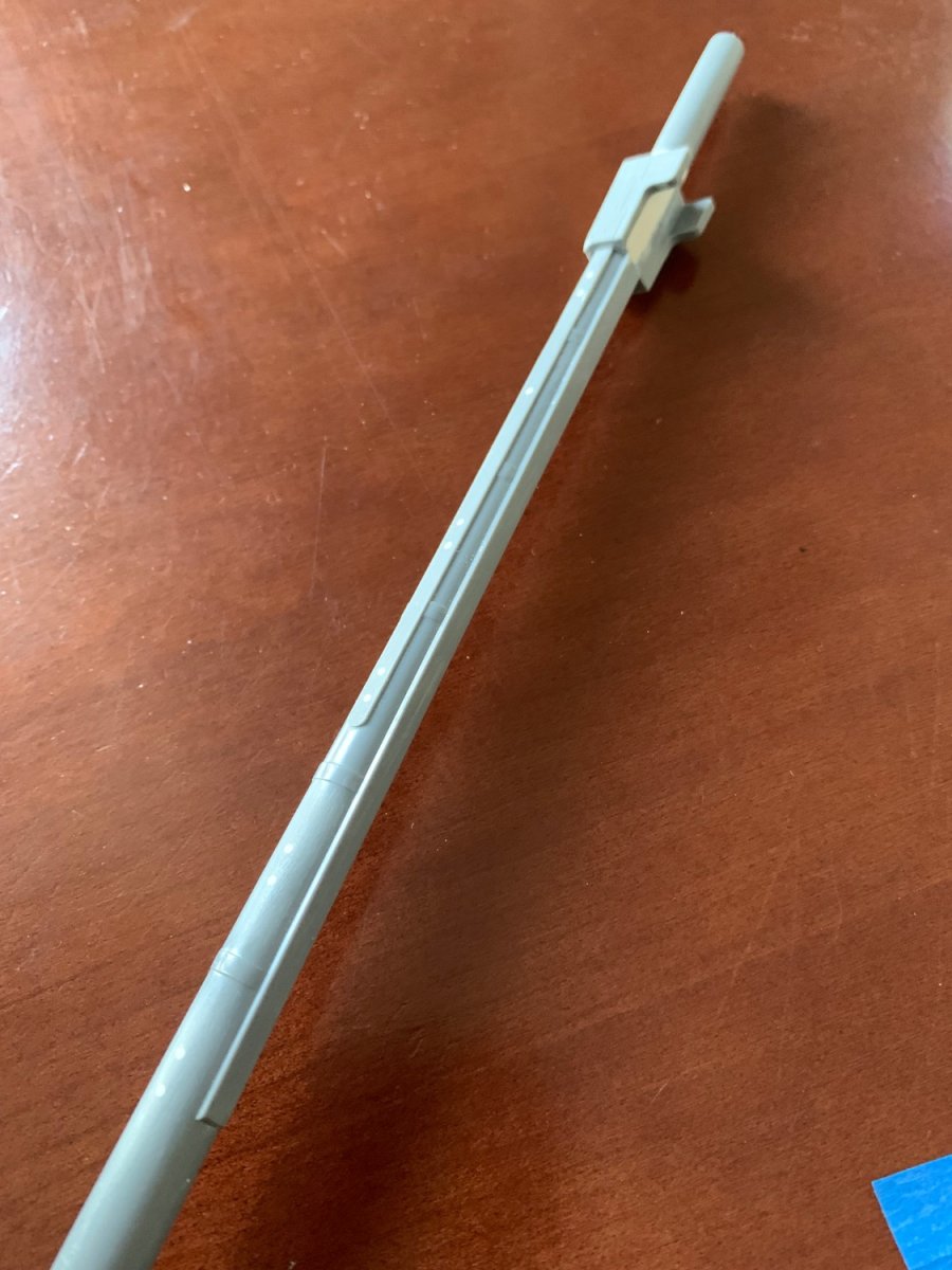
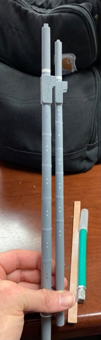
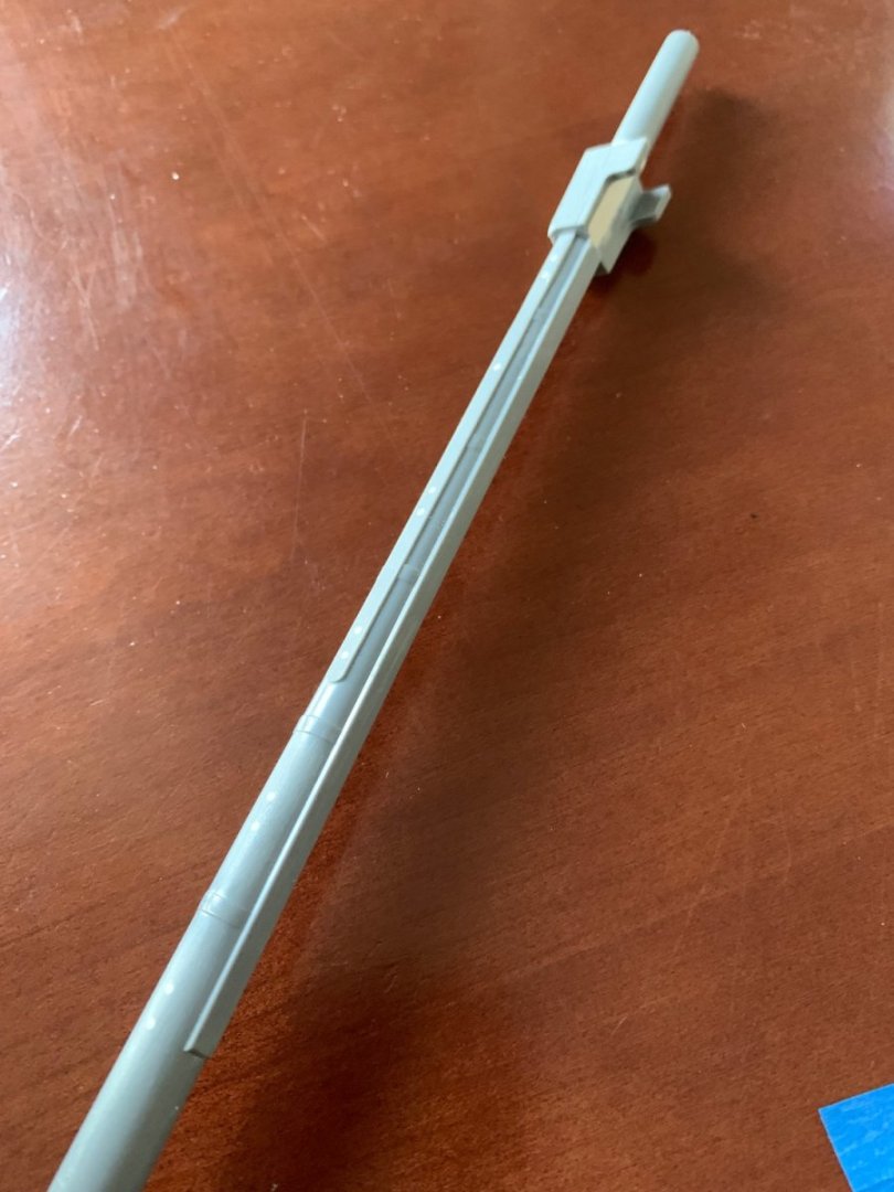
I can’t remember who, exactly, but a while back someone very astute pointed out that a 17th C. lower mast of this time period would not have been equipped with either front or side “fish,” or re-enforcements. It is a Hellerism for them to be moulded into the fore and main masts: They are nowhere to be found in the work of leading authorities like Boudriot or Lemineur: And so, for a long time I debated whether to shave away these details. My main argument against it was a concern that doing so would make the lower masts appear too spindly - this, especially, because I had raised each mast footing by about 1/2” for better scale. The primary argument FOR doing this was that it would enable me to properly represent the wooldings with their top and bottom retaining mouldings. To apply these mouldings over and across all three fish would just look completely wrong and weird. Now that at least one big holiday is out of the way, I was looking for something to jumpstart the project again, so I decided this was a good task to finally tackle. I started with the coarse Dremel drum sander to remove the bulk of the material: The challenges with this little project are two-fold. The first is to carve-in the missing segments of the iron bands (between wooldings. The other is to maintain a smooth continuous mast taper between the bands. The pictures basically tell the story: I think this was a success, primarily because the masts do not appear spindly. Going forward, I will try to be somewhat more present with this project. Our CYO basketball schedule kicks off this weekend, and there are a lot of games in the first few weeks. Then, of course, there is Christmas to contend with. Who was it that said “life is just one G’damn thing after another!”? Anyway, I think that’s me saying that. Thank you for looking in and for your continued interest in this project.


- 2,699 replies
-
- 18
-
-
- heller
- soleil royal
- (and 9 more)
-
Super impressive!
-
This is all completely fascinating, Peter, and your idea to divide each station into three parts is ingenious. I have one curiosity, though. The side parts of each bulkhead, that taper into frame shapes above the lower gundeck - why not make these from solid timber like maple, boxwood or pear? Is it mainly a consideration of radial shrinkage of solids, joined to stable plywood?
- 30 replies
-
- 3
-
-
- Corel
- wappen von hamburg
- (and 1 more)
-
You are off to a smashing start, Michael. How's the condition of the plastic? Do you find that it is at all brittle or still pliable? As for square vs. round tuck, I think it likely that she had a round tuck. Your mock-up looks spot-on. Planking across the aft-transom ports should be horizontal, though. The tuck planking ends at the wing-transom.
- 324 replies
-
- 3
-
-
- Sovereign of the Seas
- Airfix
- (and 1 more)
-
This is all coming together beautifully!
-
It is nice to be reminded of this magnificent build. I hope all is well for you, and that you are able to relax and work on your model from time to time. Best, Marc
-
First of all - mission accomplished! Nothing about the way all of the stern elements come together is kit-like. Bravo! The thing I like so much about the Speedwell is that in addition to her elegant up-sweeping sheer-line, she has such a nice balance of carved work that really bring a lot of visual interest to the model. As always, your engineering of these processes is ingenious. That is quite an experience you are in for to be involved with a major film production, starring several of the best actors of our time. The recognition and opportunity are well-deserved! Happy Thanksgiving to all!
-
Happy Thanksgiving, Gary! You’re off to a great start, and I look forward to your return when you are ready to do so. Best, Marc