


drobinson02199
-
Posts
1,045 -
Joined
-
Last visited
Content Type
Profiles
Forums
Gallery
Events
Posts posted by drobinson02199
-
-
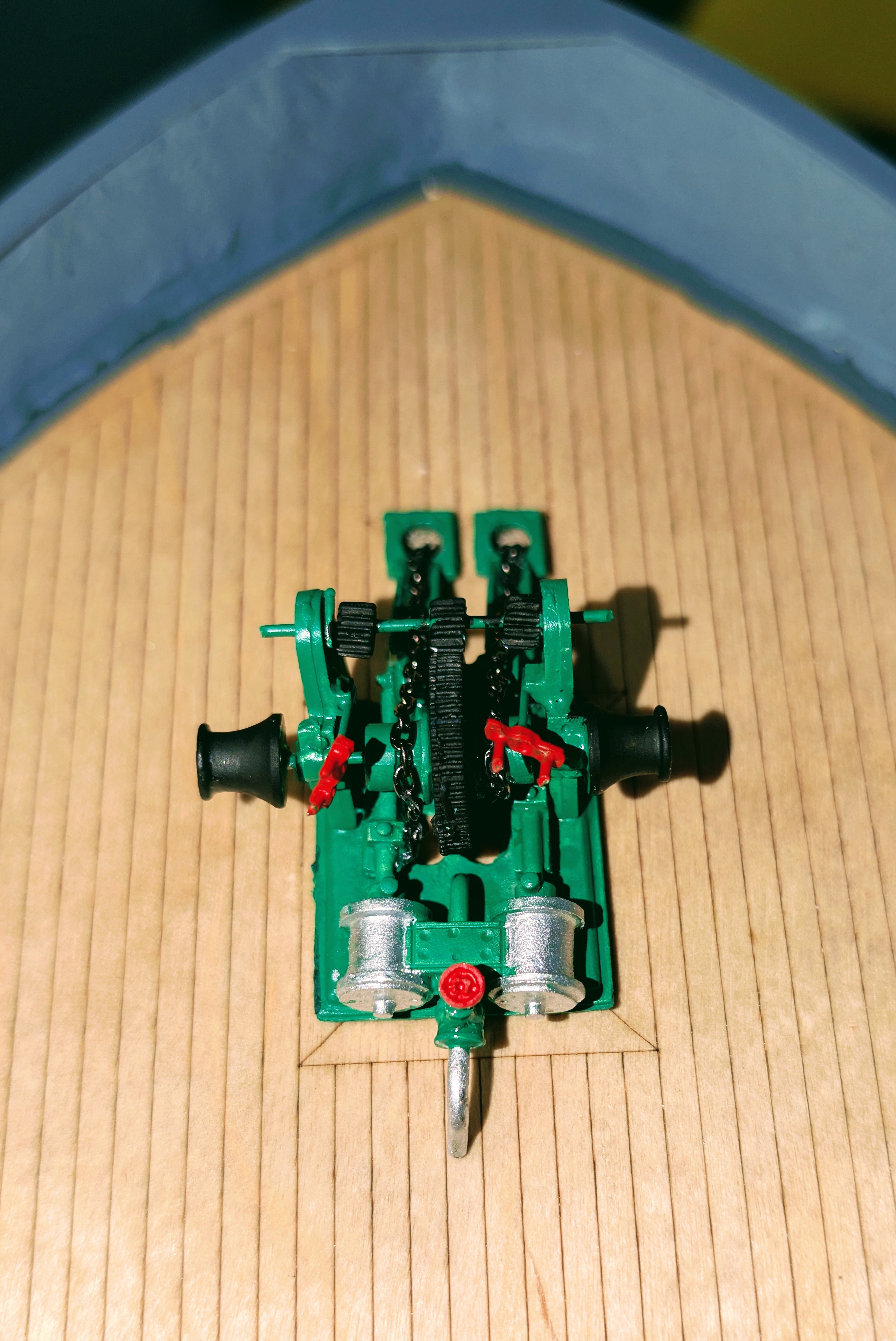
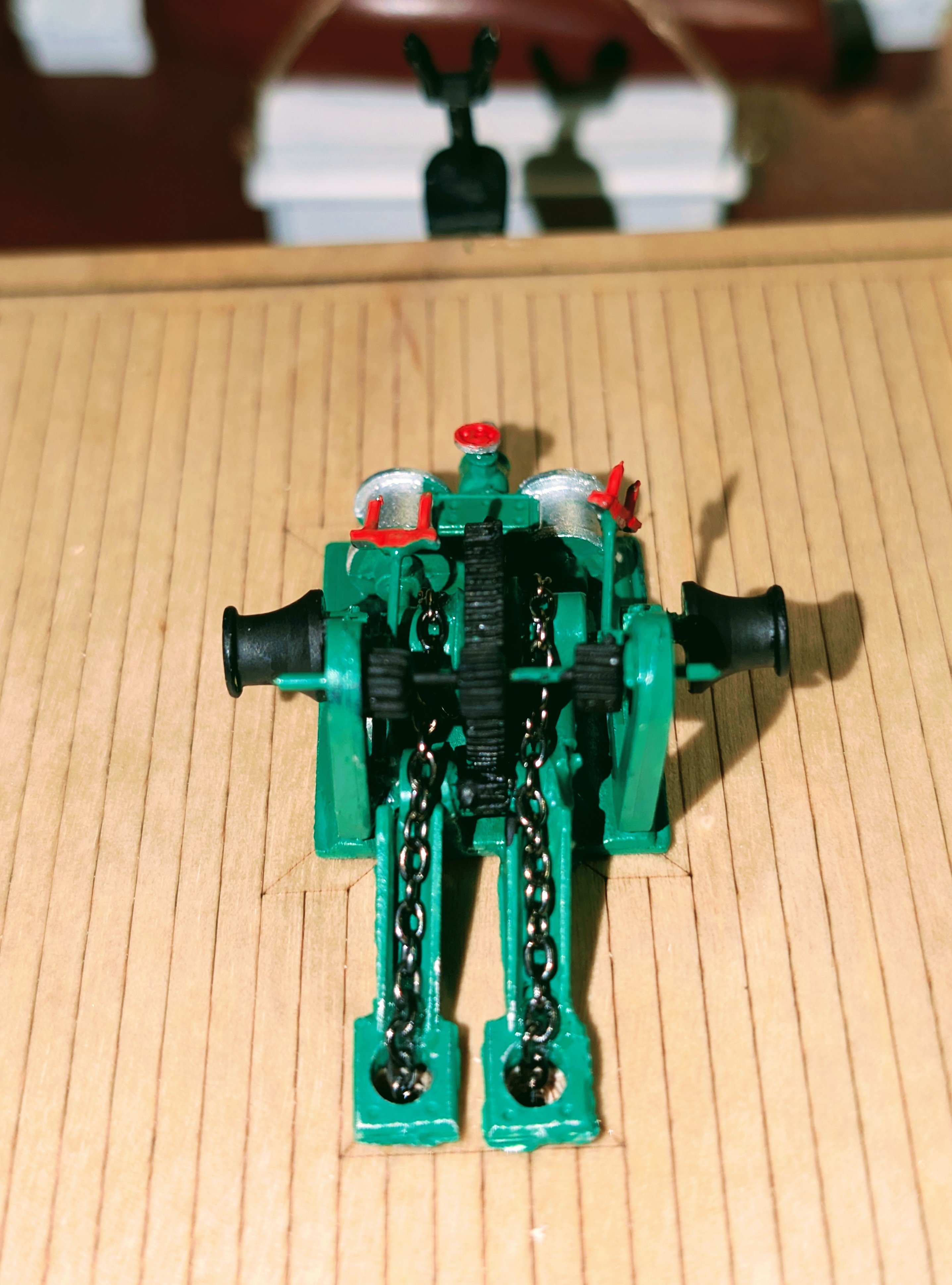
Here's the anchor windlass, which is a nice-looking assembly, completed and glued in place on the fo'c'sle.
I really like this kit -- it's a fun build, and as the ship nears completion, it looks really nice. But it blows my mind that a kit from Caldercraft that costs as much as this did (over $600) doesn't include parts such as the anchor chain, or ANY rigging line. They aren't missing -- I have searched the parts list electronically and there is no anchor chain included.
So given the ambiguity of the instructions that I've mentioned several times above, this is a kit for experienced builders for two reasons: first, you have to decide on your own how to build a lot of things, and second, you need to have built a bunch of kits so that you have a good spare parts box. 😁 That's where the anchor chain shown came from, and that's where my rigging line will come from.
Regards,
David


-
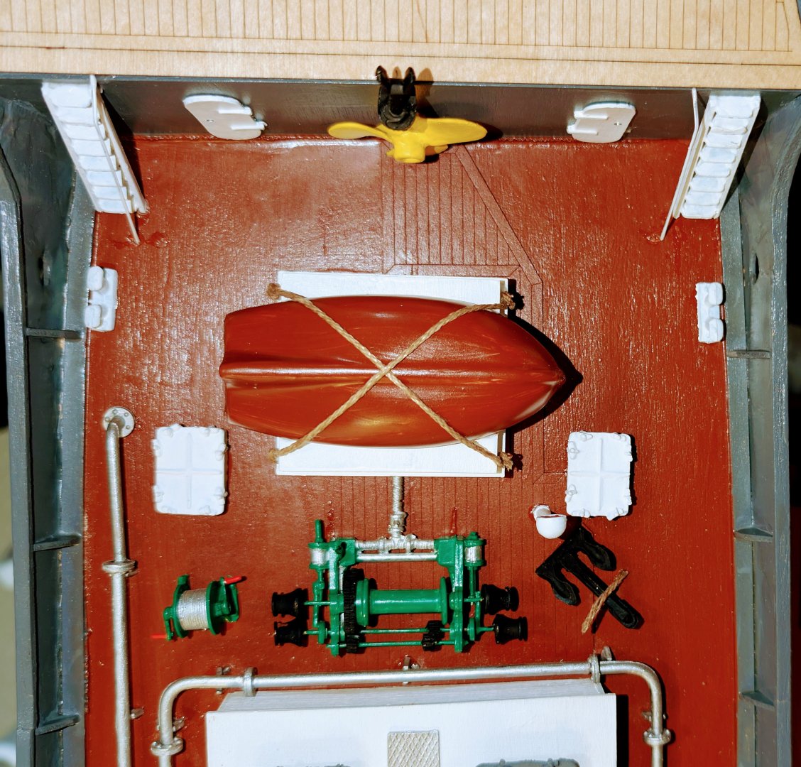
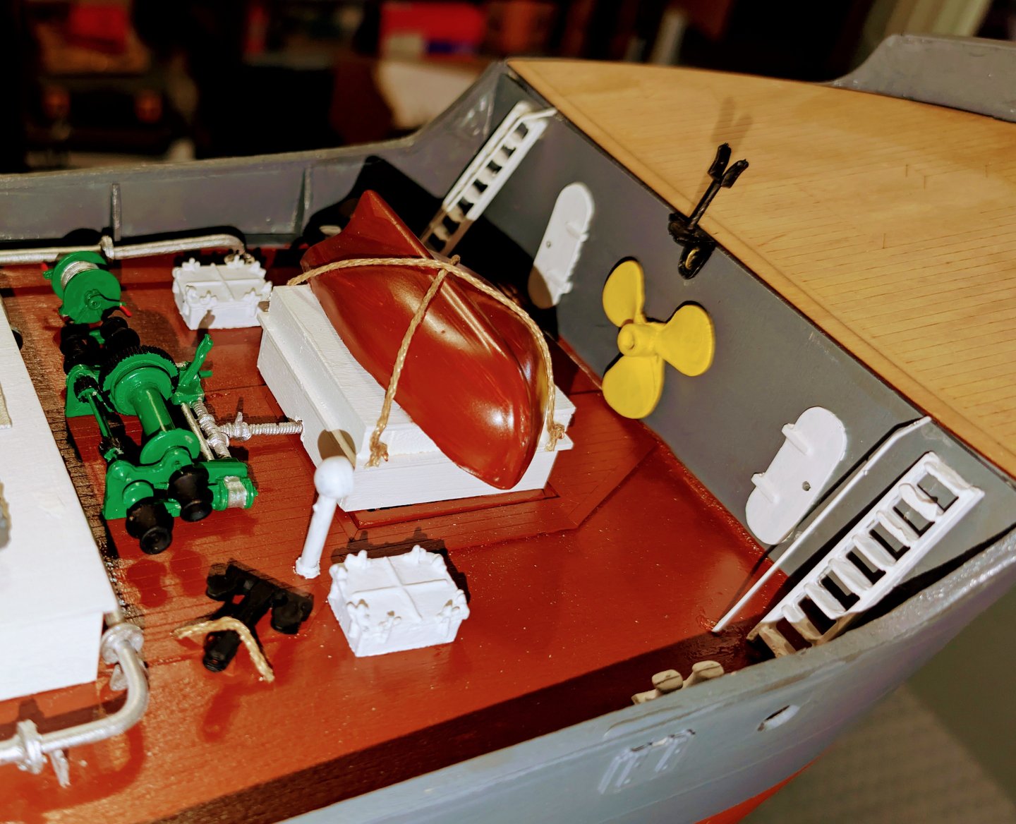
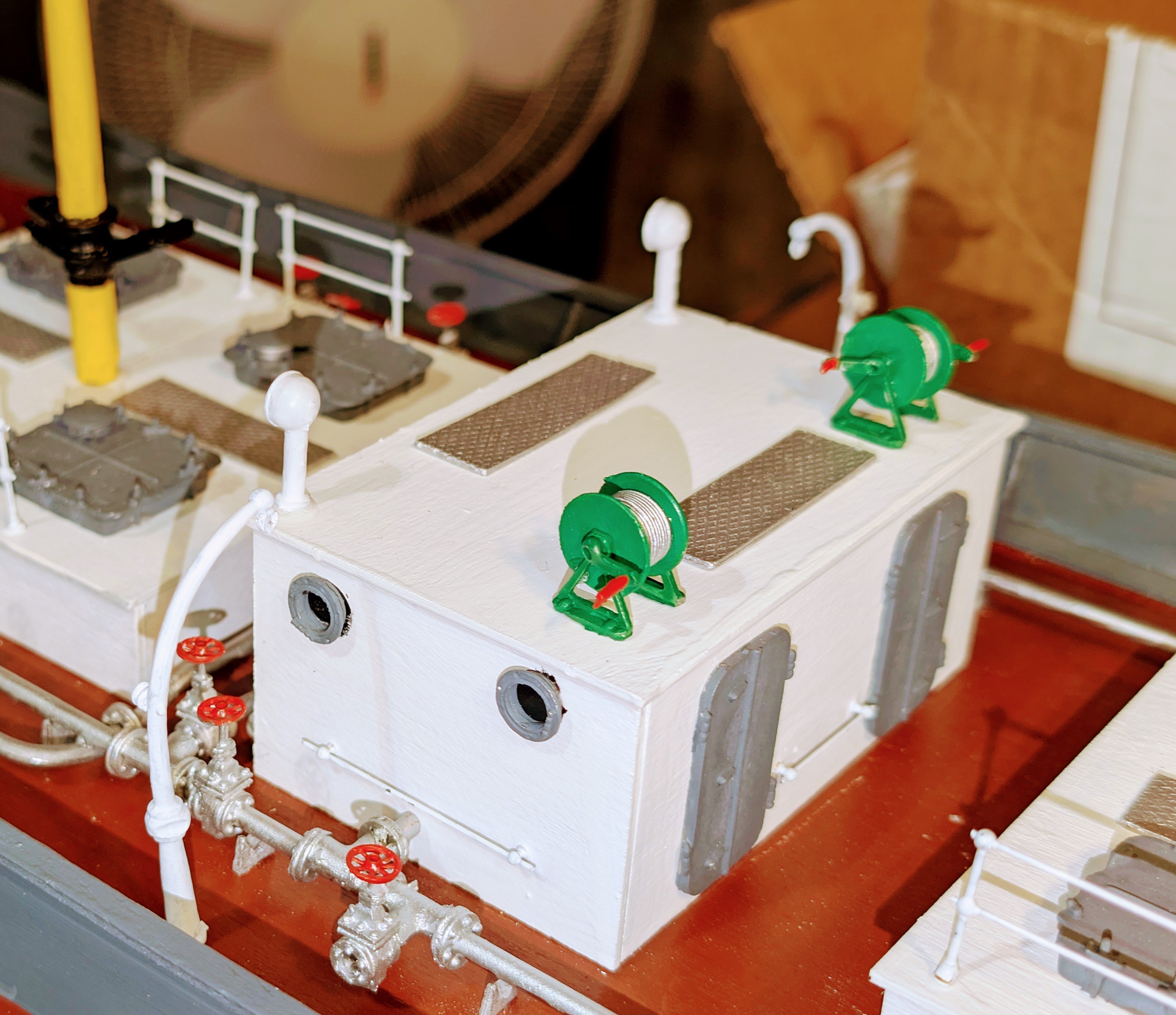
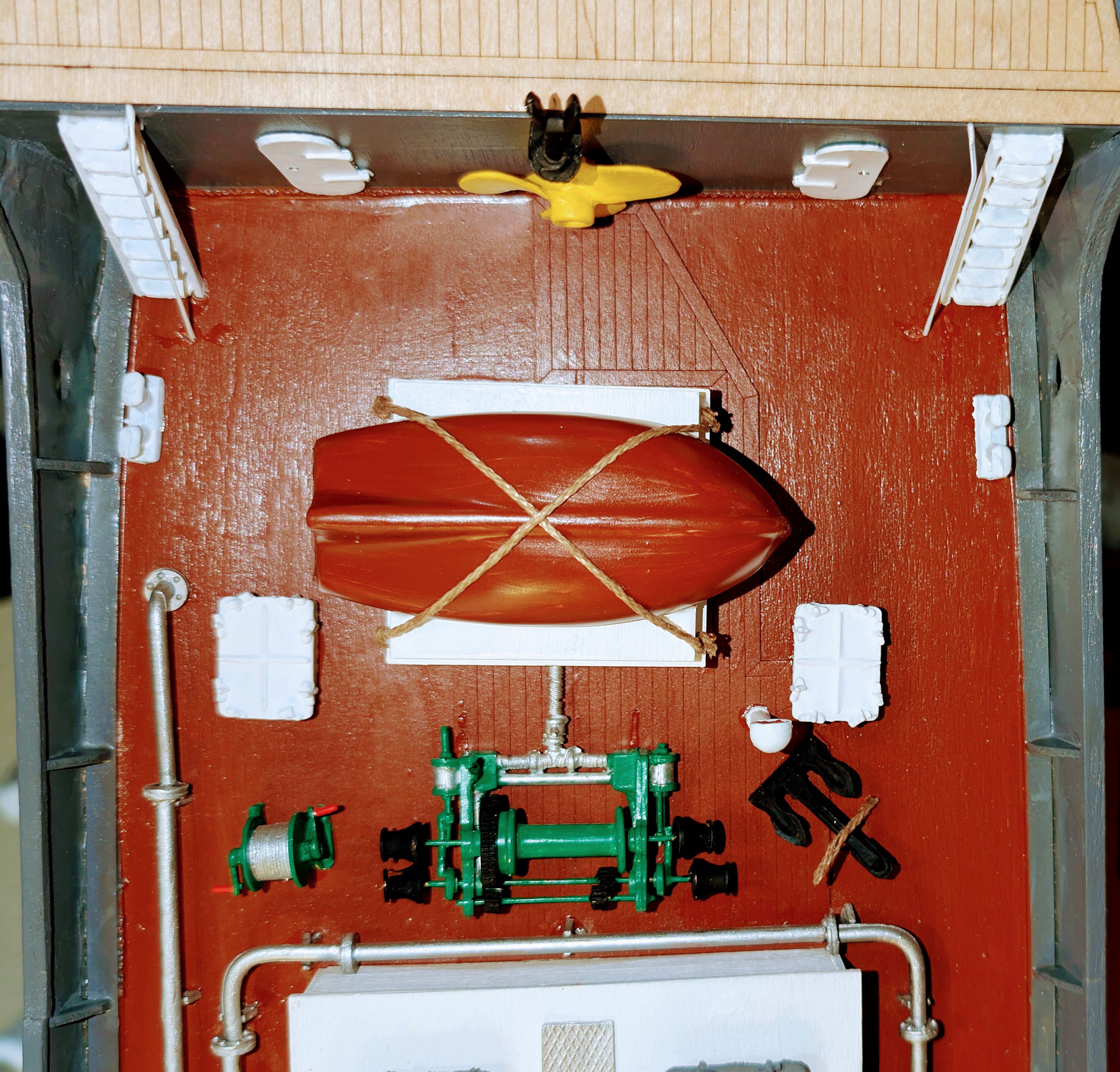
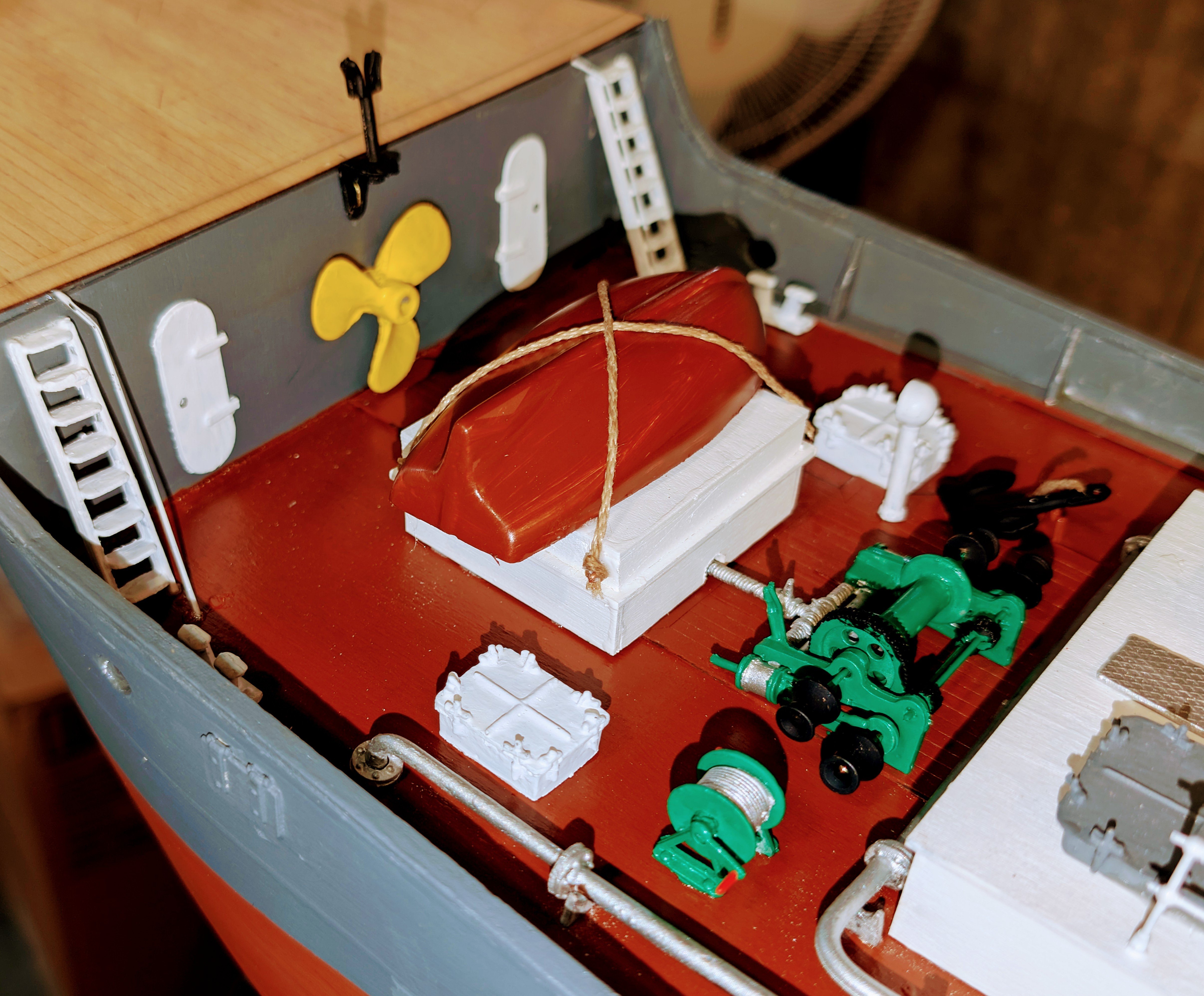
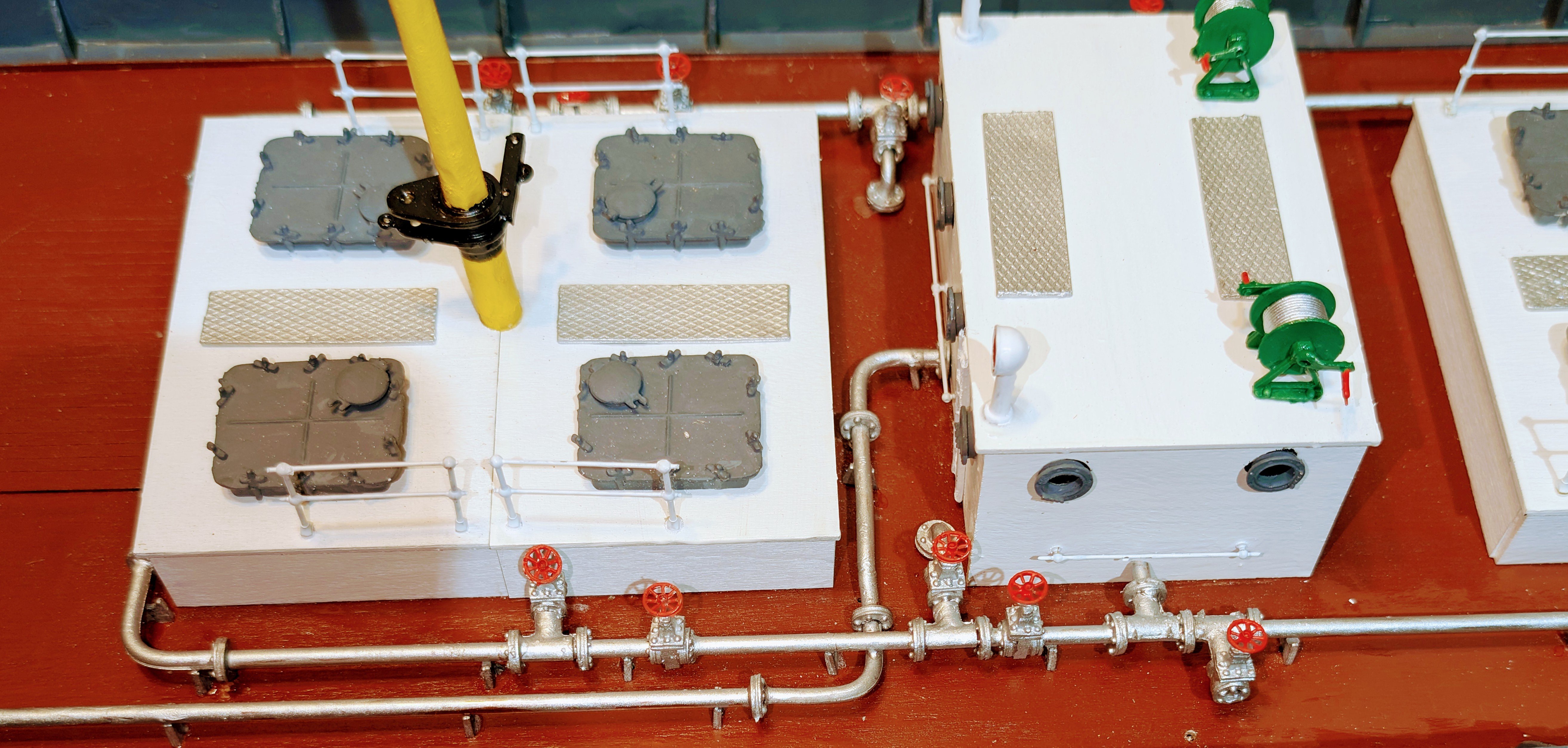
Finished up the forward deck. Some of these structures I had completed previously.
I'm not sure what the midships lifeboat stanchions are for. Maybe cargo??
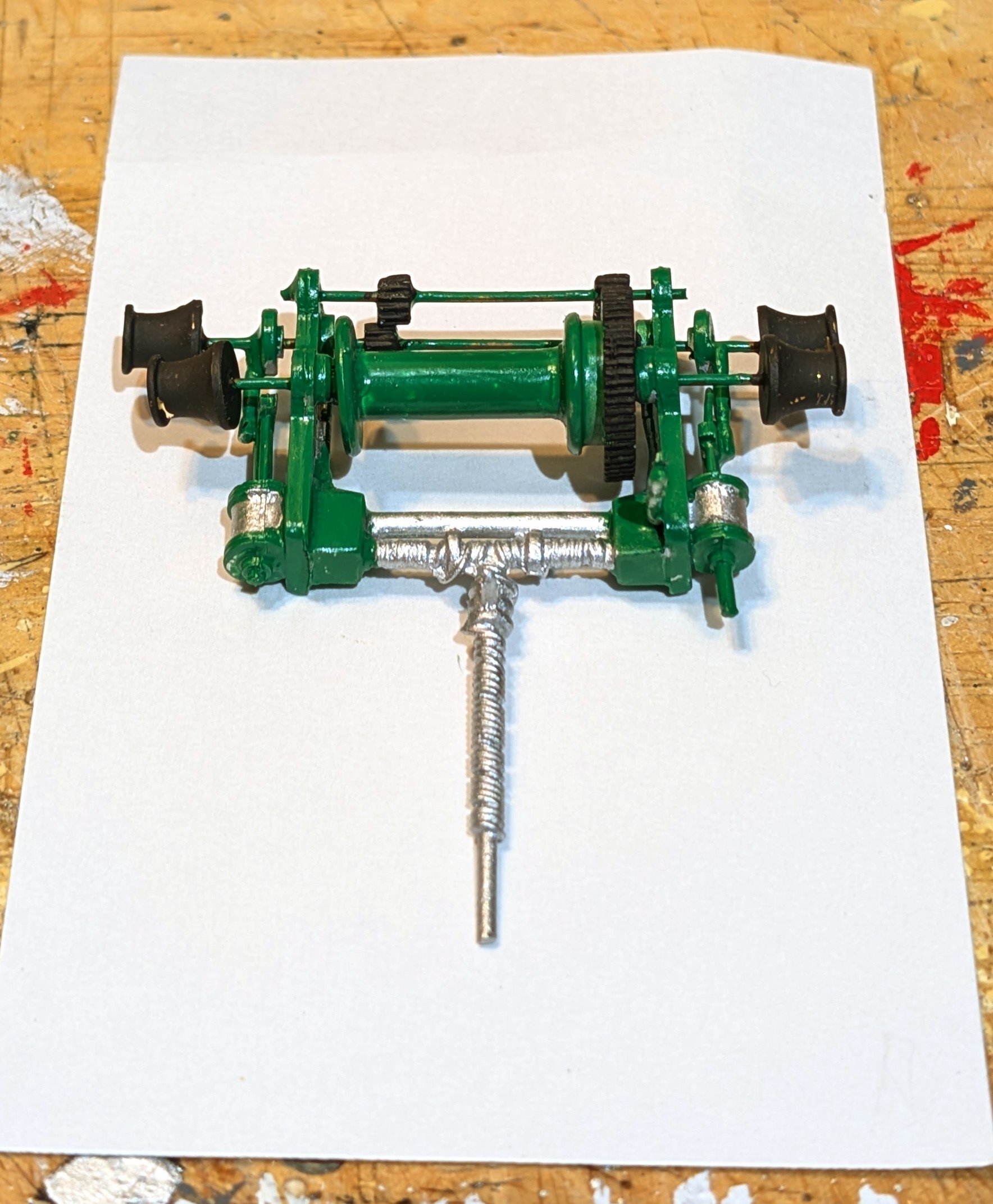
The cargo winch is a nice looking assembly.
Now on to the fo'c'sle, then the boom and rigging.
Regards,
David


-
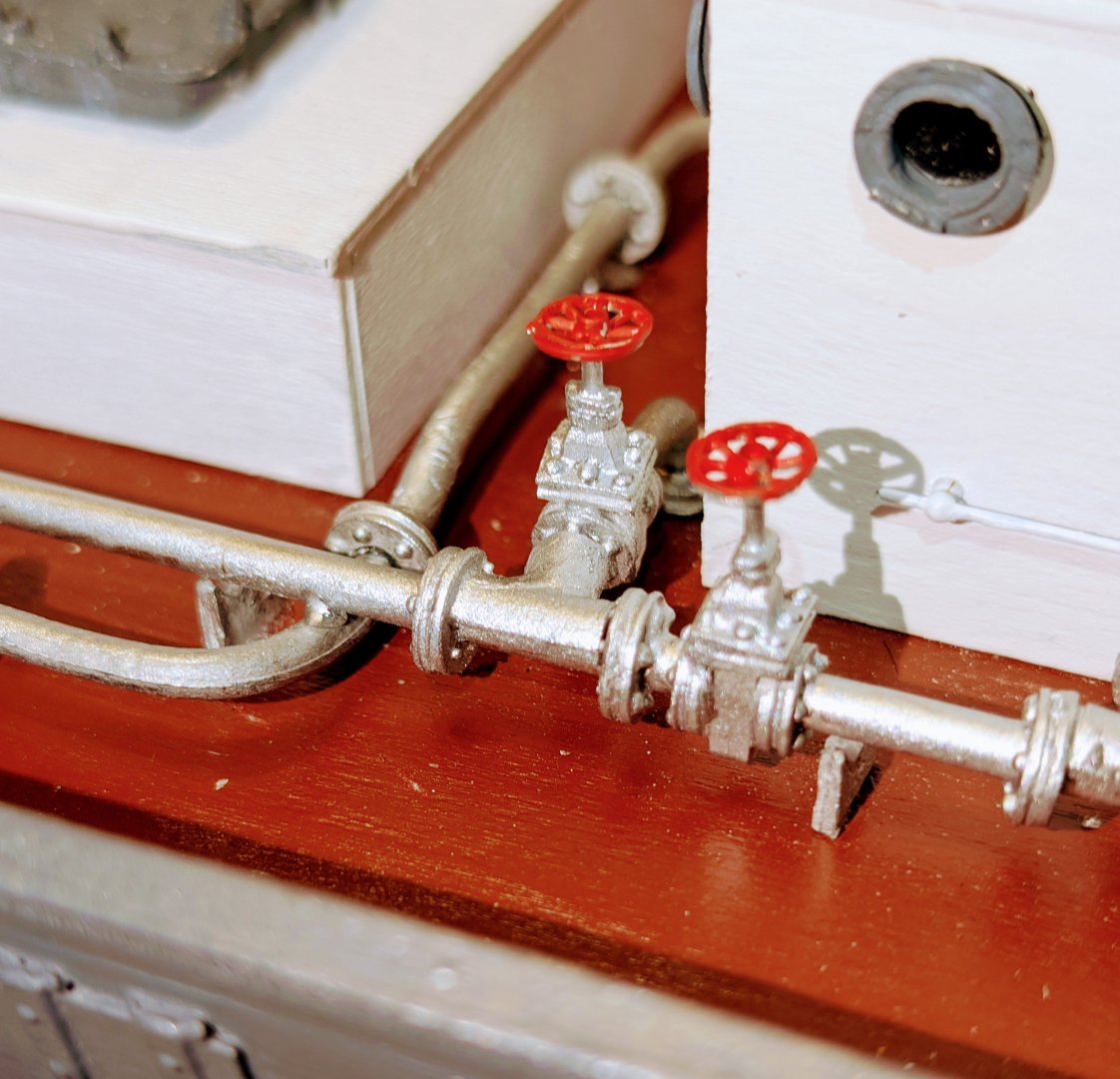
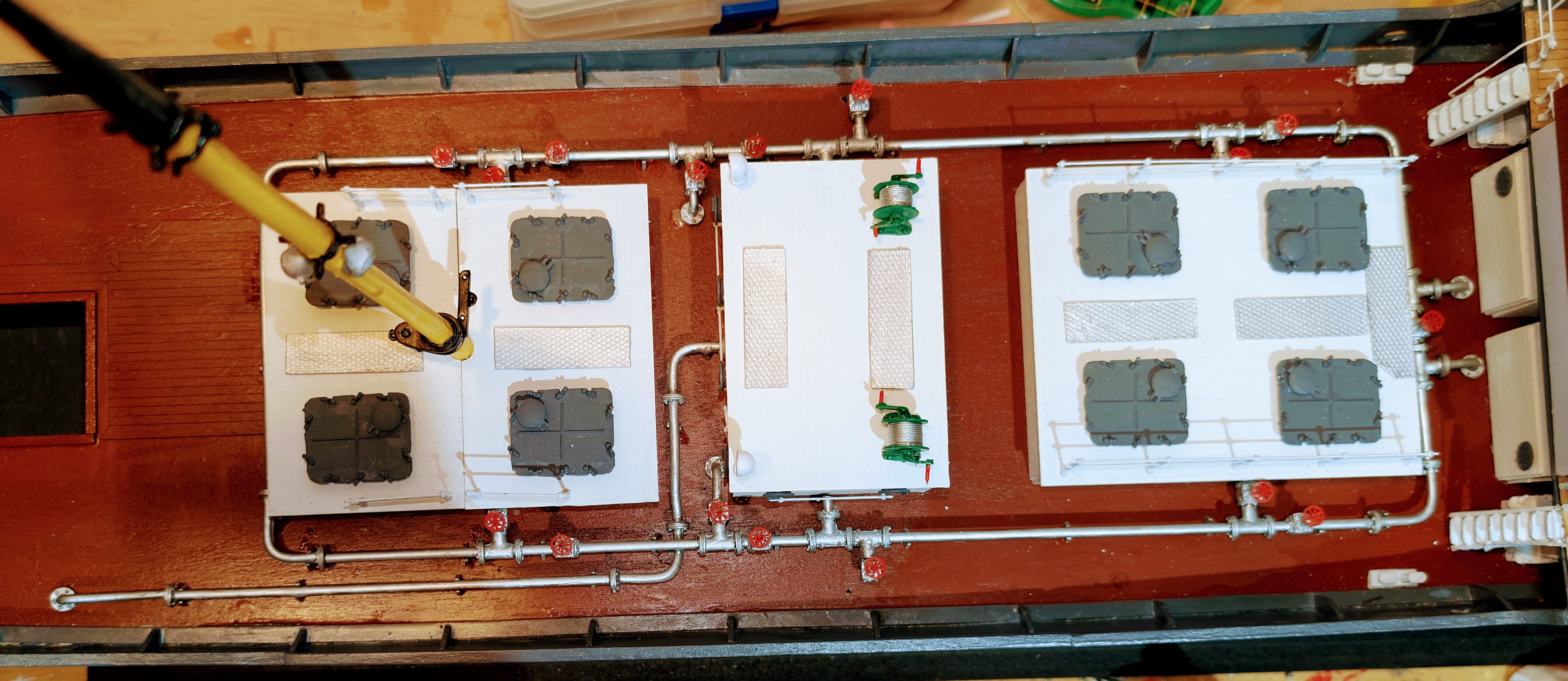
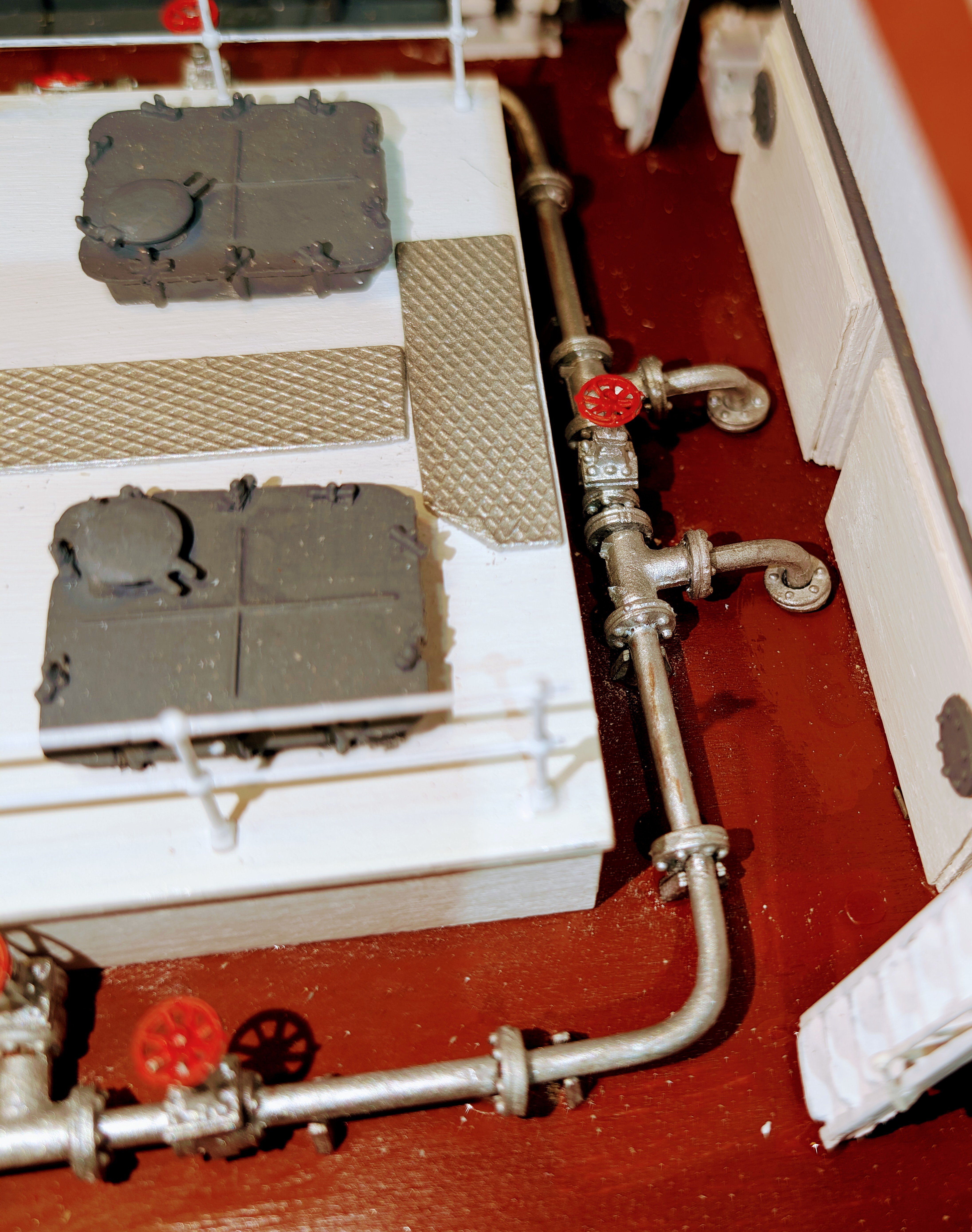
Finished the piping. As I noted above, I didn't follow the instructions and instead built it in sections, dry-fitting as I went along, and I woiuld strongly recommend that approach. The long sections are made of steel rod that is copper-colored, so I used silver metallic paint.
The part where one pipe passes under the other takes some trial and error dry-fitting to get right.
Regards,
David


- yvesvidal, ccoyle, Landlubber Mike and 4 others
-
 7
7
-
-
I want to get the pipework done before putting on the forward hatch (which I have built and painted).
This is the start of that process. I first scanned and copied the "to scale" pipework diagram so that I could cut and lay down the original as a template. It's not quite a clean fit, so I had to enlarge the openings and cut it into several segments, but got it to work. I also had to considerably shorten the pipes that go into the deck on the left, as the length of the ones on the drawings wouldn't fit.
Then drill all the marked spots for pipe brackets and push (not glue yet) those into the holes at the bottom. One good thing about how they did this is that I could cut one single length of the copper-colored rod and slide all the fittings onto it.
I turned the corner on the right to stabilize the rod so that I could fix the four valves aligned in the upright position. Now I'll start creating the three side branches that go off this section. None of it is glued down yet, so once those branch sections are done and fixed, I'll remove it and paint it, then remove that part of the drawing and glue everything down.
The instructions say to do this for the entire outer ring in one section before removing and painting, but because of structure top overlaps that won't work.
More to come.
Regards,
David


- king derelict, ccoyle, yvesvidal and 1 other
-
4
-
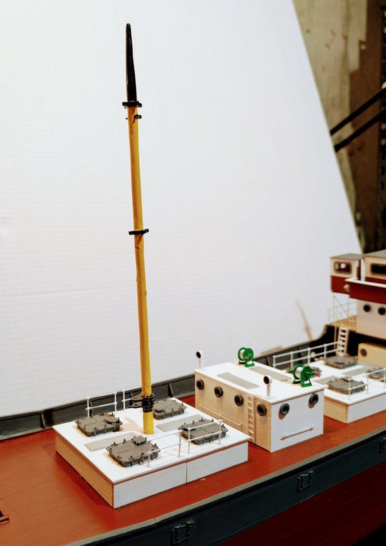
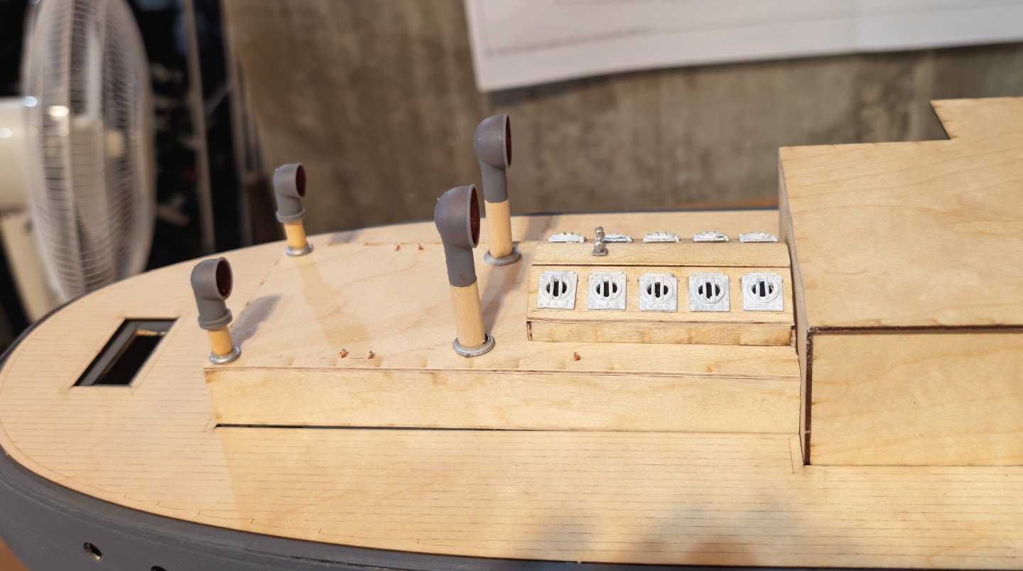
Built the forward tank top and the main mast and installed the mast. The bottom of the mast is imbedded into a wood block that sits on the inside bottom of the hull, so I glued in one half of the tank top, then used a spirit level to get the mast properly aligned, and then dripped glue onto the block followed by instant set.
Now from the drawings and all of my photos I'm puzzled again by what goes between this structure and the hatch (or I should say HOW the next fittings go, coupled with the oil piping), so I think I'll build the cargo winch and then see how that dovetails with the piping.
Regards,
David
- egkb, king derelict and yvesvidal
-
3
-
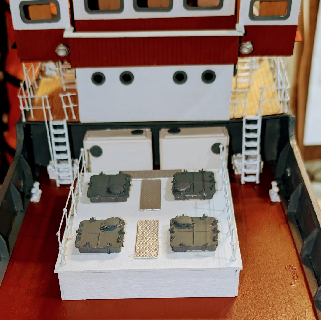
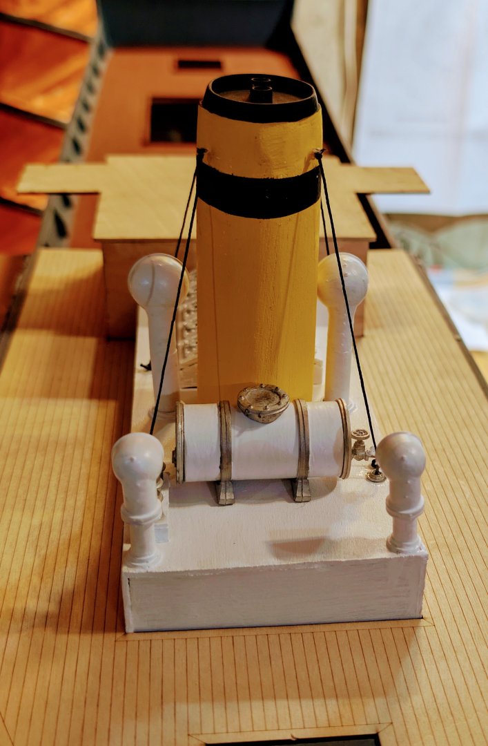
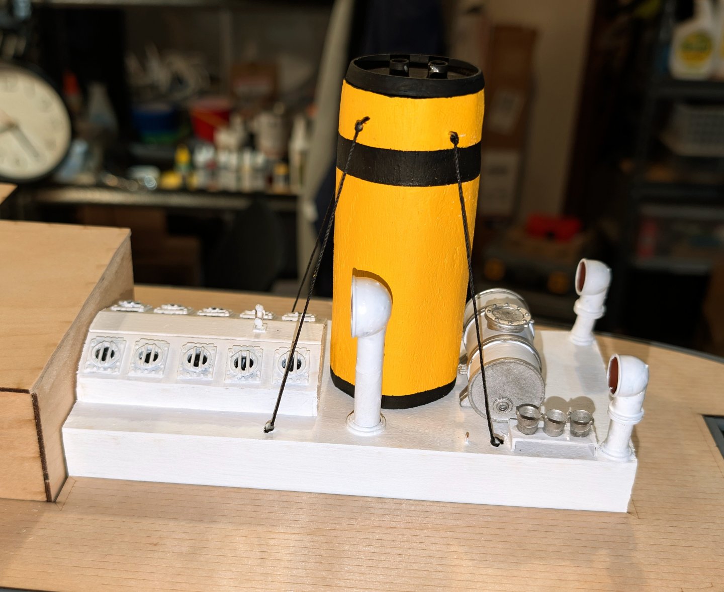
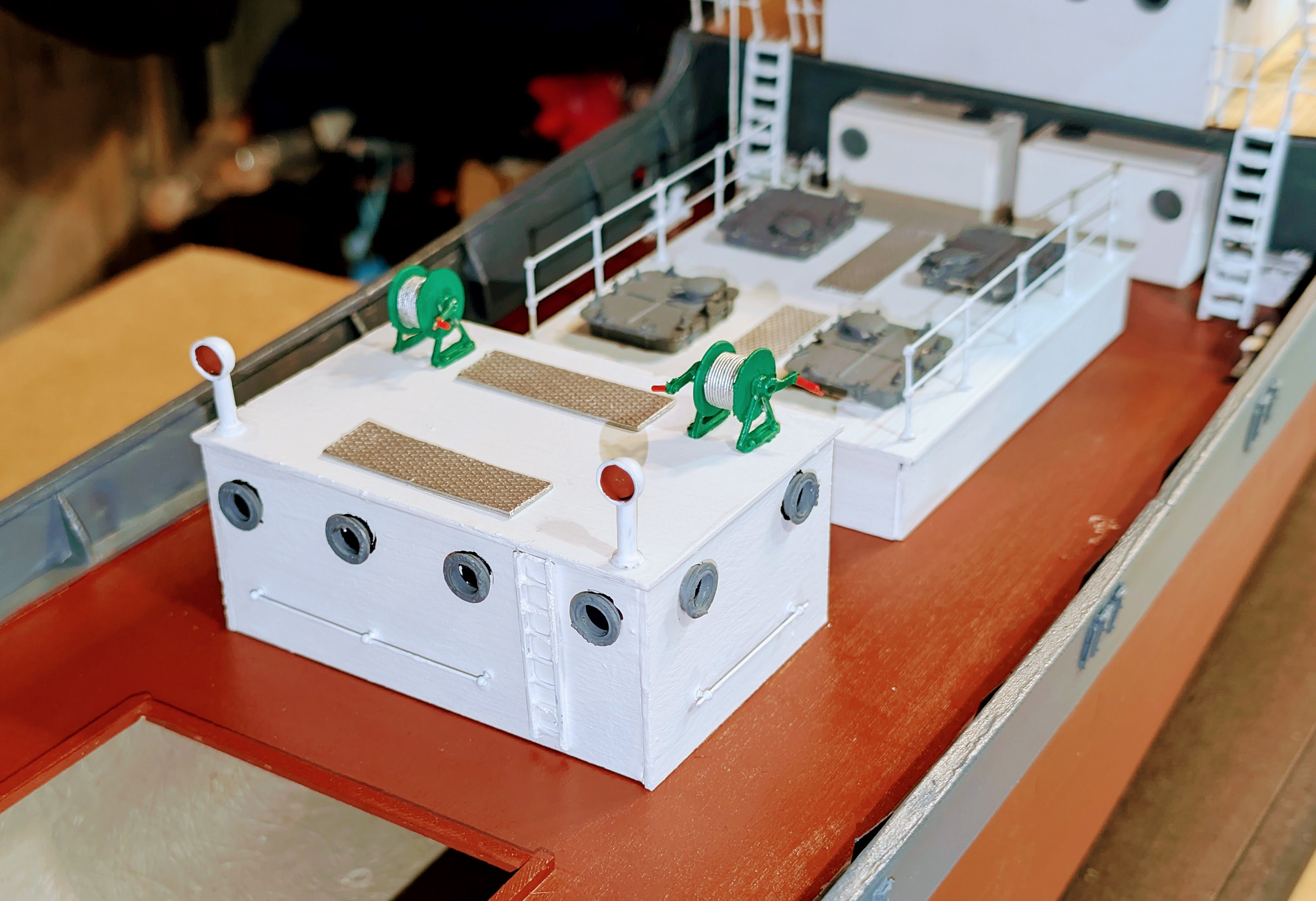
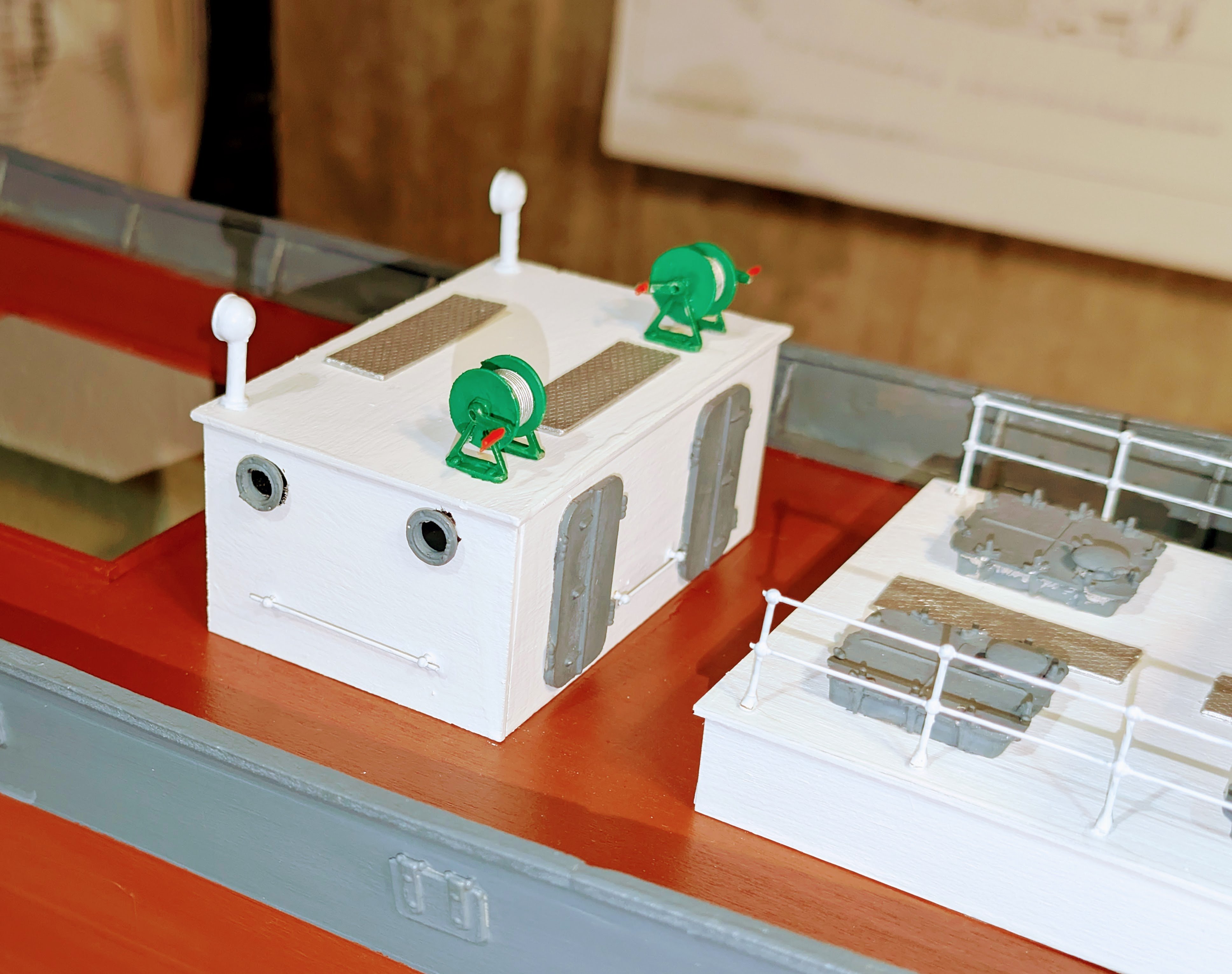
Pump house built and installed.
Regards,
David
-
Aft oil tank top installed.
Regards,
David

- king derelict, yvesvidal and egkb
-
3
-
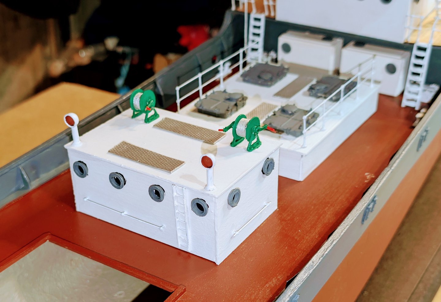
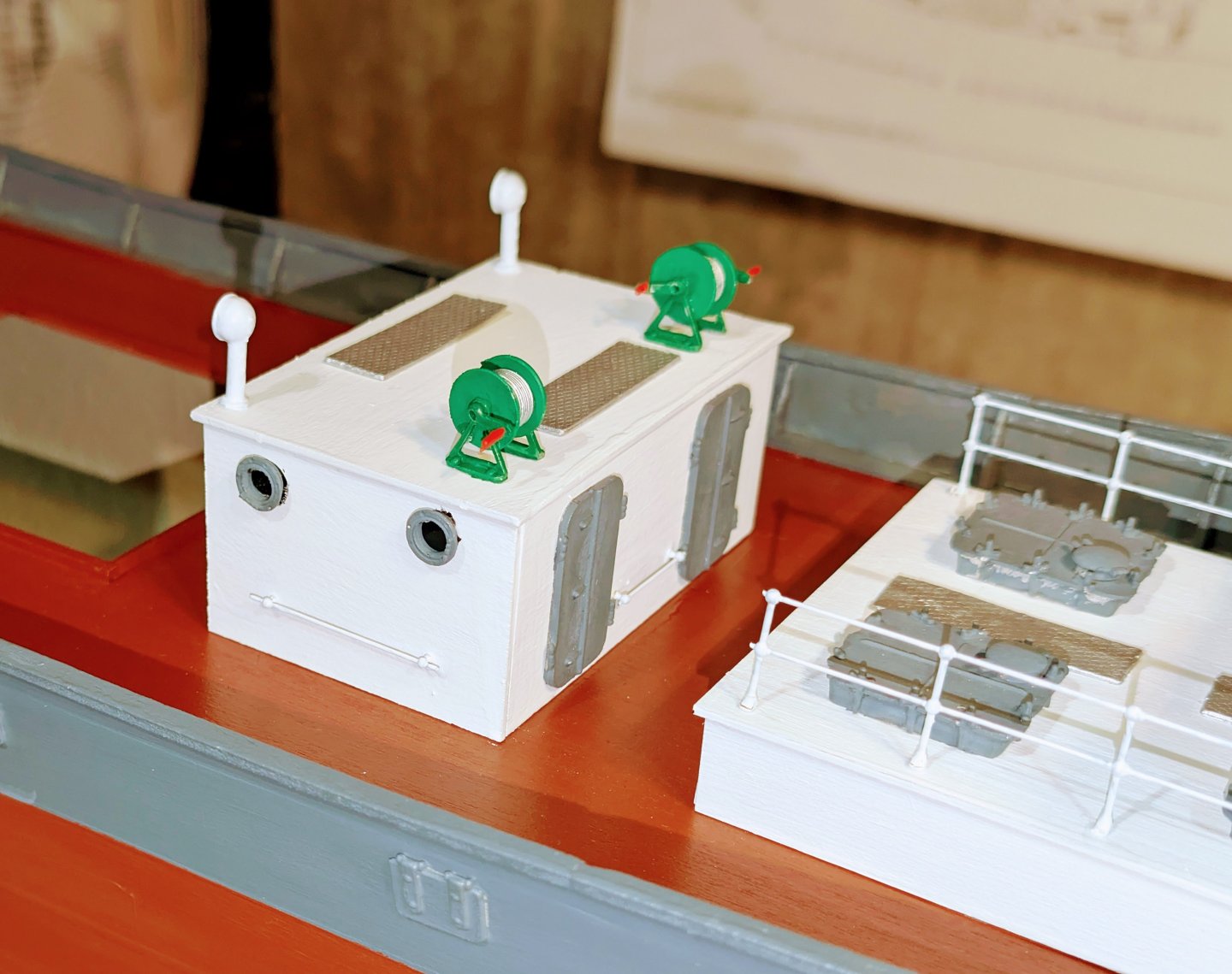
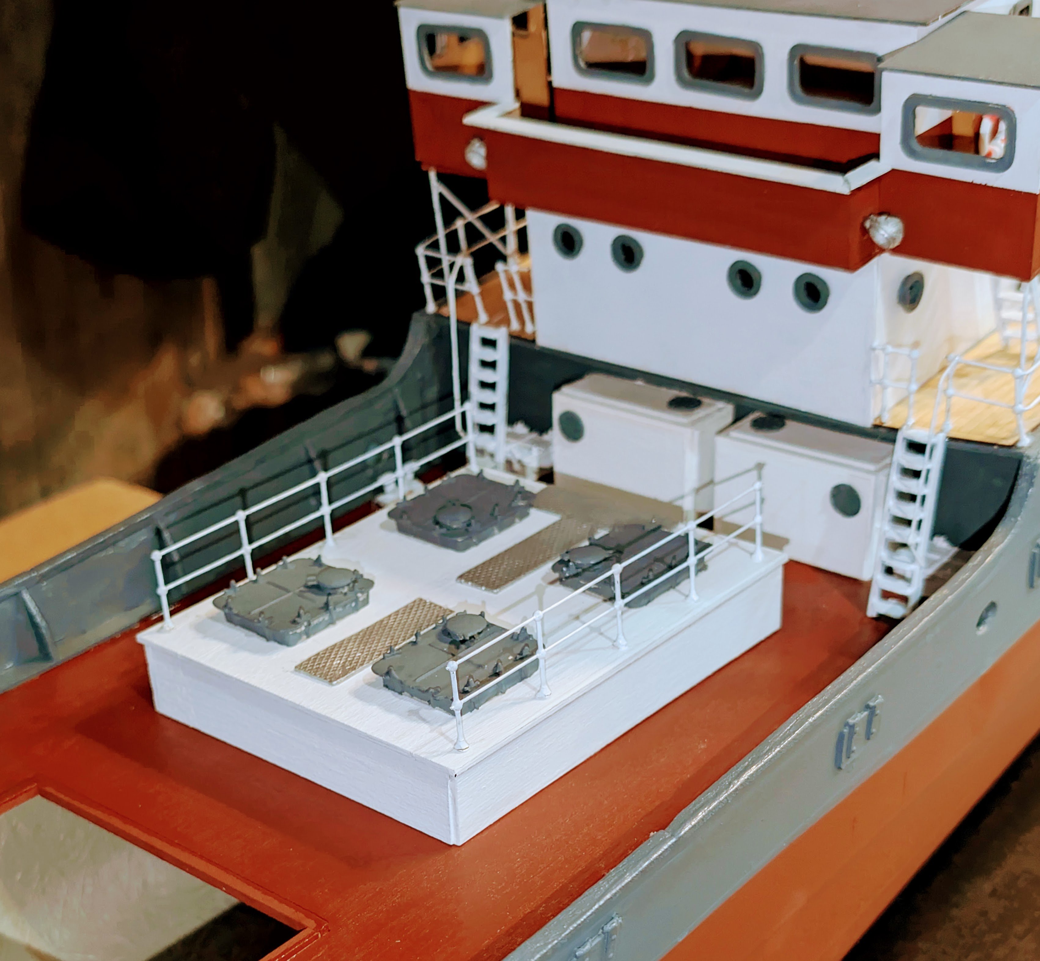
Water tanks installed under the stern balcony.
Regards,
David

- Harvey Golden, egkb, ccoyle and 2 others
-
5
-
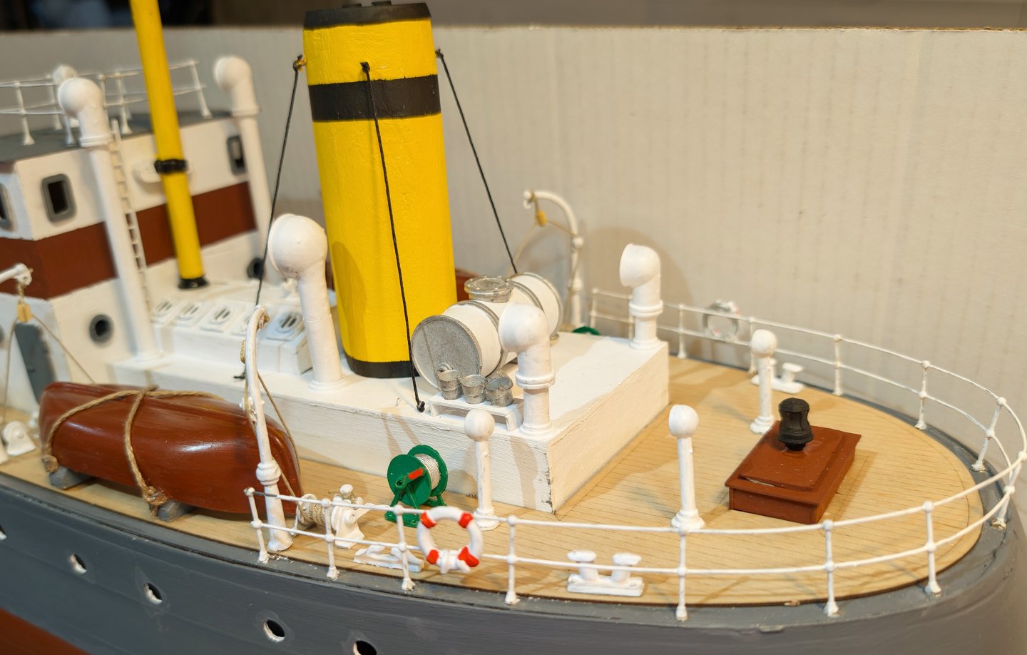
I've finished the stern structures, with the exception of one fitting (see below). Since my last post, added the rear railing, plus wire winders, life rings, chocks and fairleads, as well as the second boat with davits and rigging. Also added tall vents and the mast.
The one fitting I haven't added goes in front of the capstan housing at the rear. The problem is that I can't figure out which of the cast parts to use based on the plans, and the instructions (which just have a numbered part listing). My pictures from the internet shed partial light. So I'm going to wait to the end and see what cast parts are left over, and see if that sheds light on what to install. 🙃 This one of the continuing challenges of working with the instructions for this ship -- but it's still an interesting build.
Regards,
David


-
I've installed the first lifeboat. There are three options: upright (then you have to fit out the interior with wood seats), covered (you need to find some covering material and somehow color it), or inverted, the way I've done it, which also seems to me the most logical way to store a boat to keep the inside dry.
The boats are molded styrene, and when you paint them, the paint mars REALLY easily, so after multiple touch-ups I varnished it to protect the paint job.
The davit rigging assumes that the falls are attached inside the boats, and that on launching the boat would be flipped over so the falls could then be used to lower it.
Finally, the manual calls for double block rigging, but I got lazy and used a single.

Regards,
David


- SiriusVoyager, egkb, yvesvidal and 1 other
-
4
-
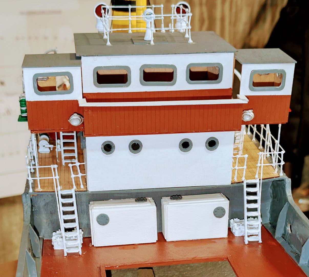
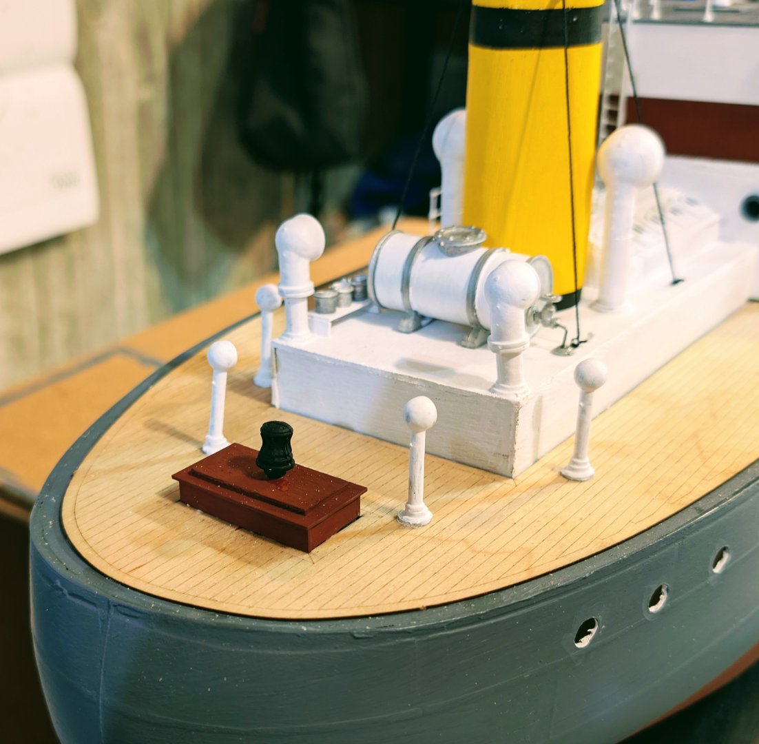
Added capstan housing and ventilators to the stern.
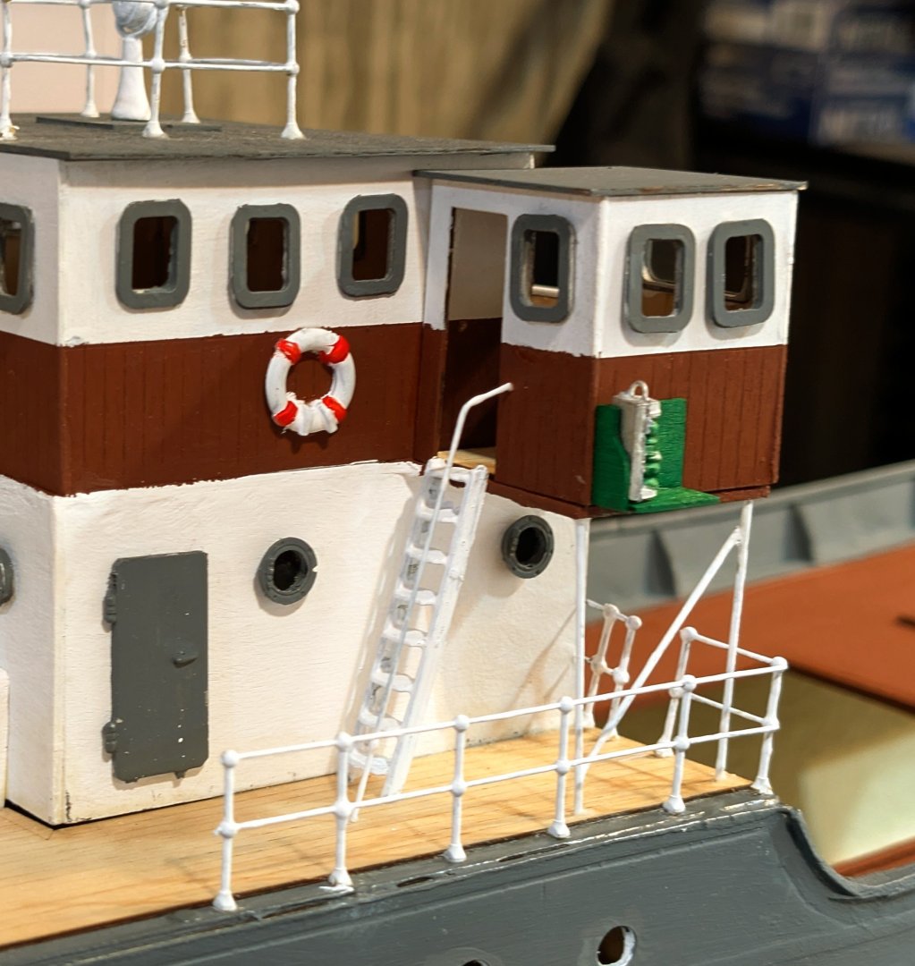
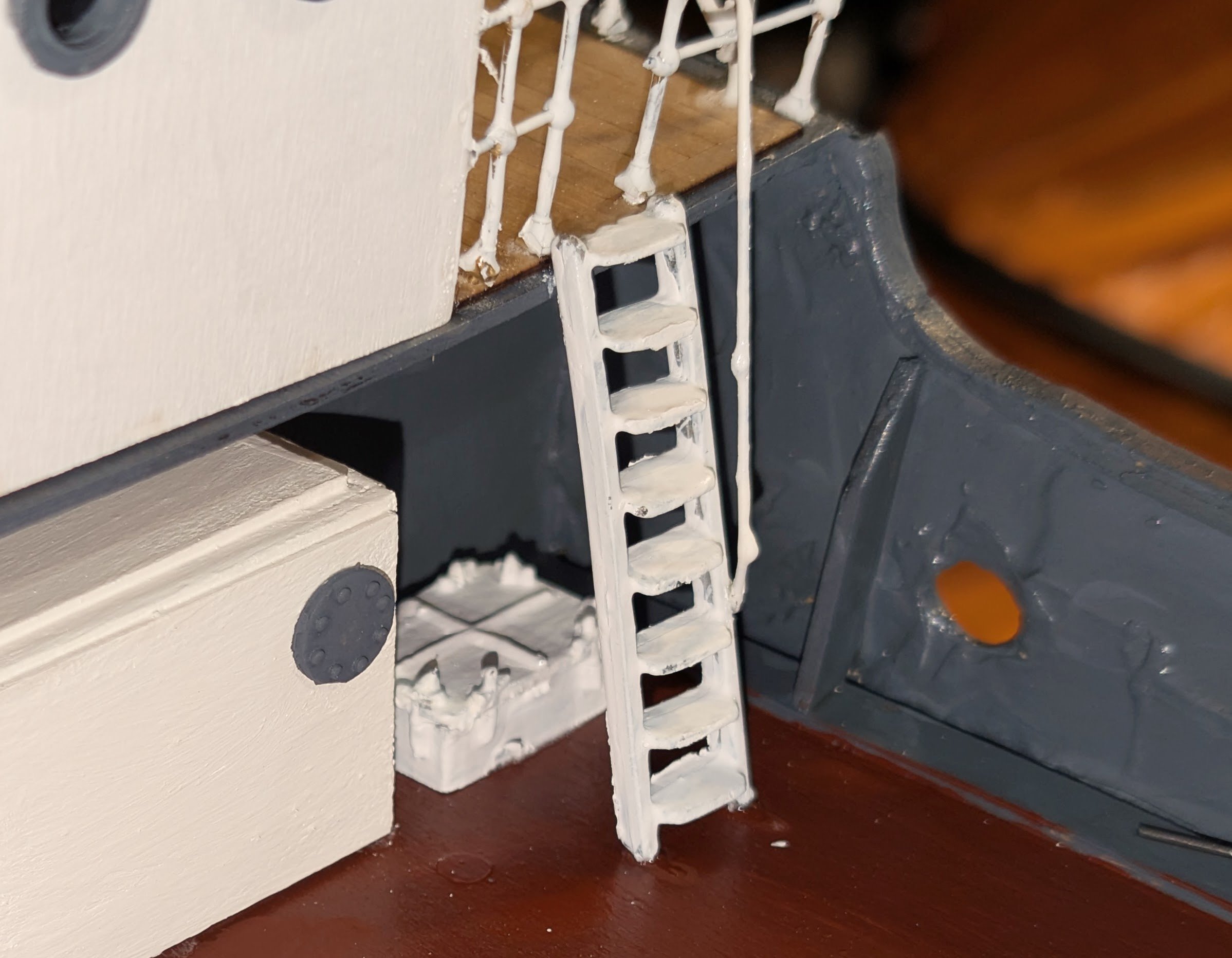
Added life ring, navigation lights, ladder and side railing to the bridge/wheelhouse.
I'm going to wait until the end to touch up all the paint splatter.
Regards,
David
- egkb, ccoyle, SiriusVoyager and 1 other
-
4
-
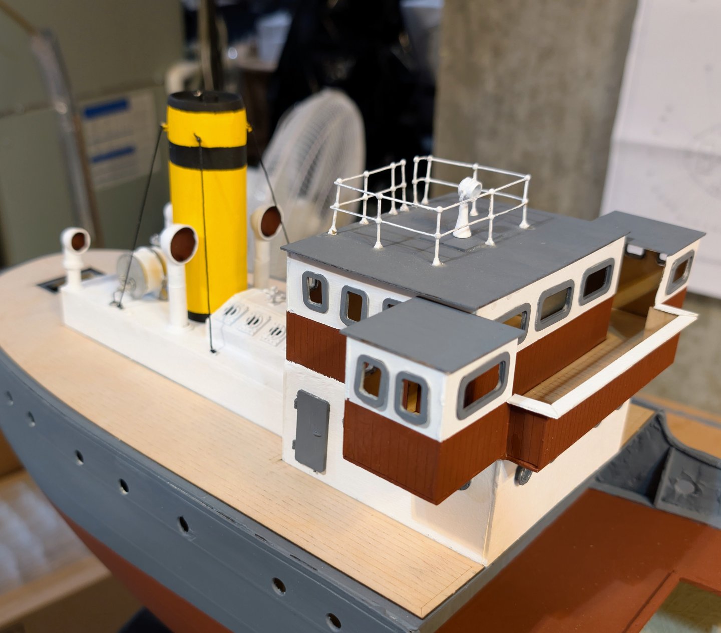
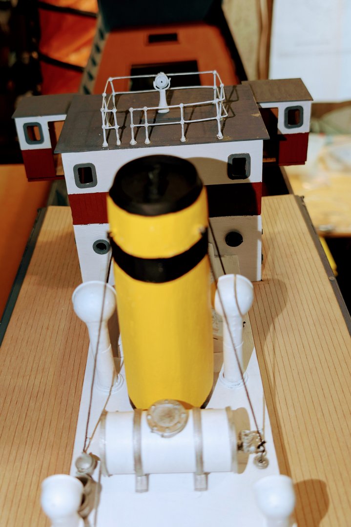
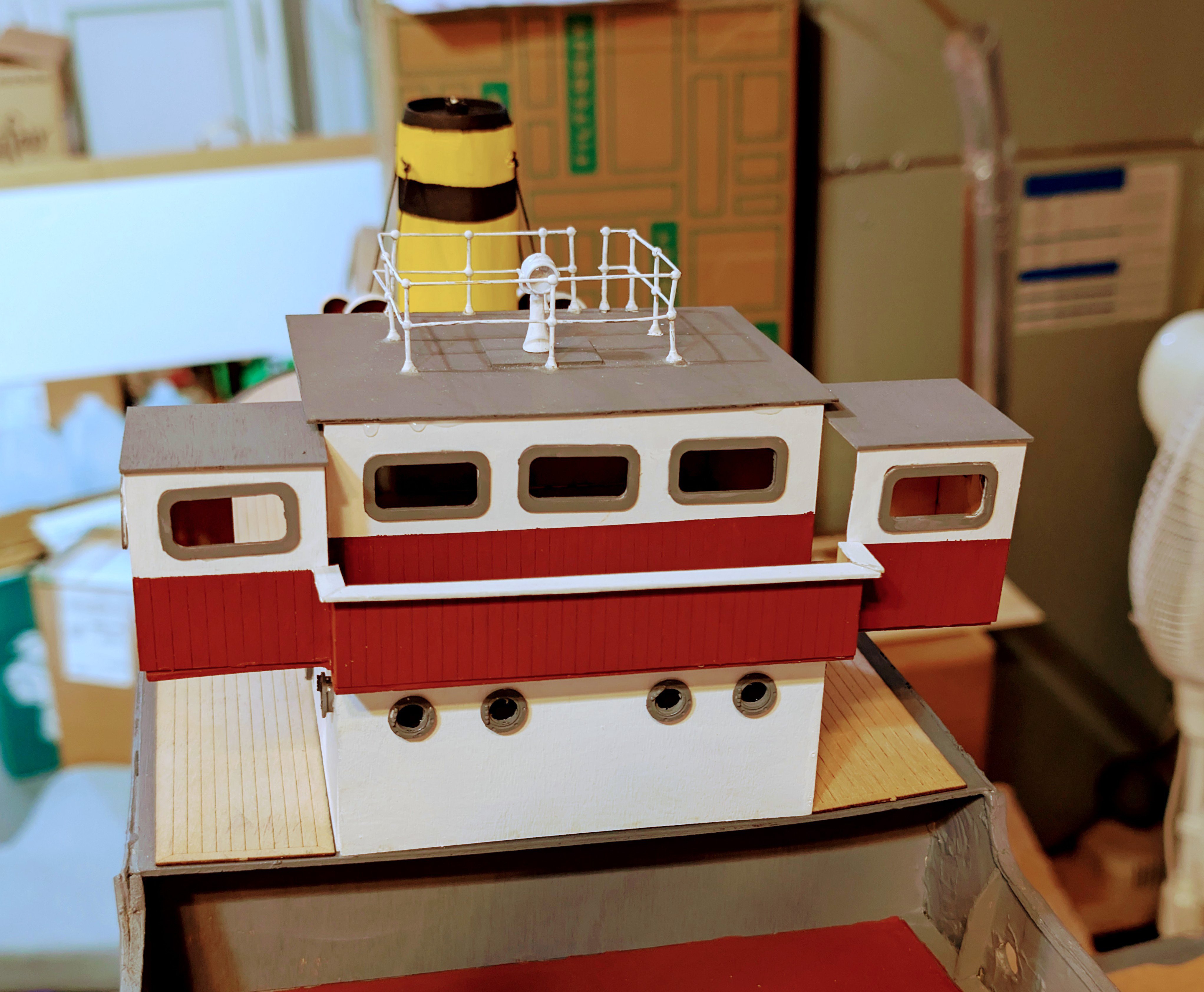
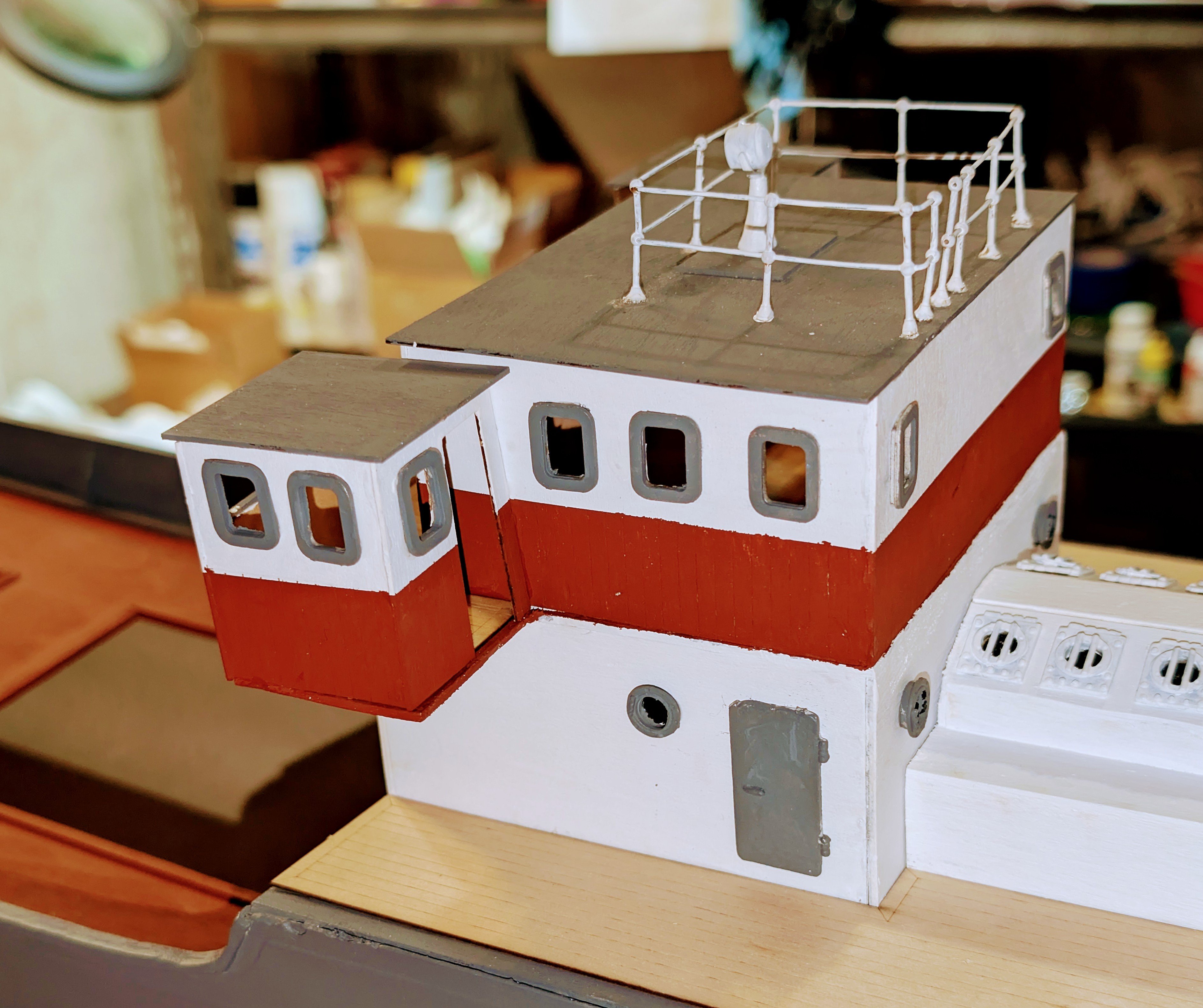
Bridge and wheelhouse finished, and shown dry-fitted in place. The kit calls for the windows, doors and portholes to be white, but I went with gray as I think it shows the detail better.
The railings at the top are from one continuous wire per strand, and the wire is stiff, and the 90 degree bends are tough to get right!
Regards,
David


-
-
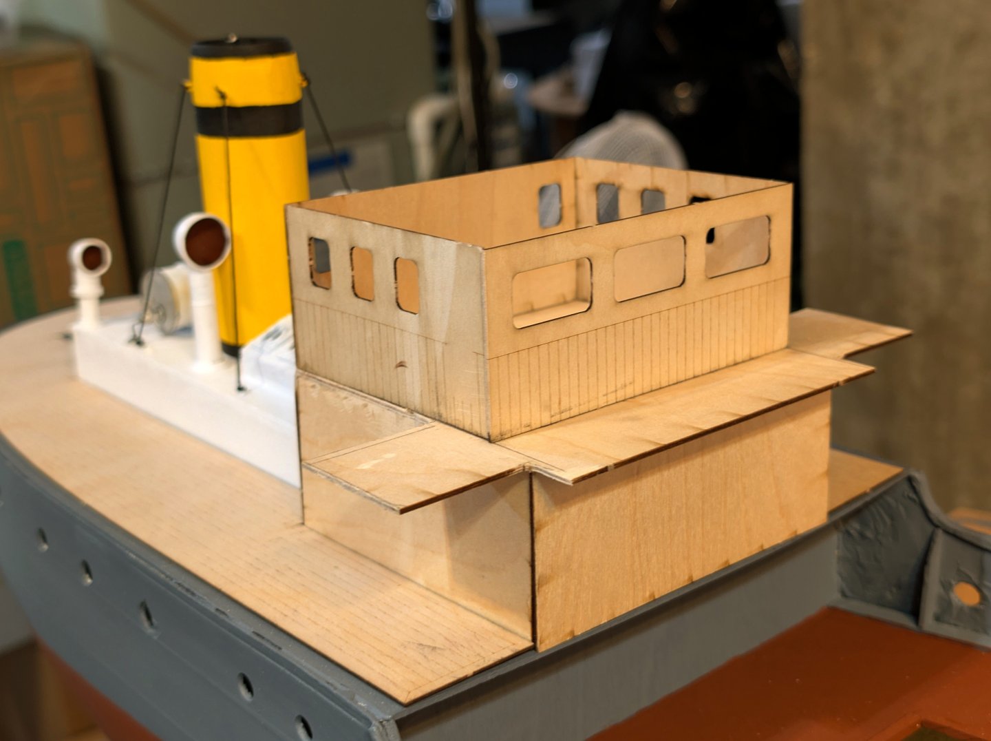
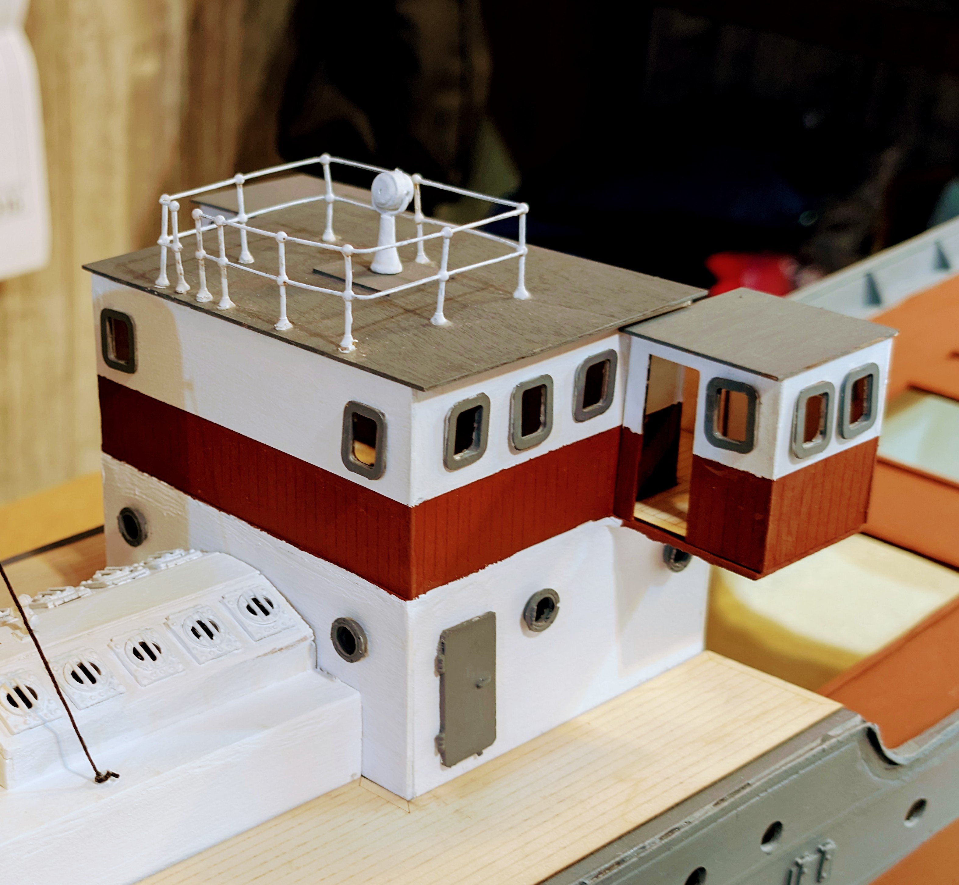
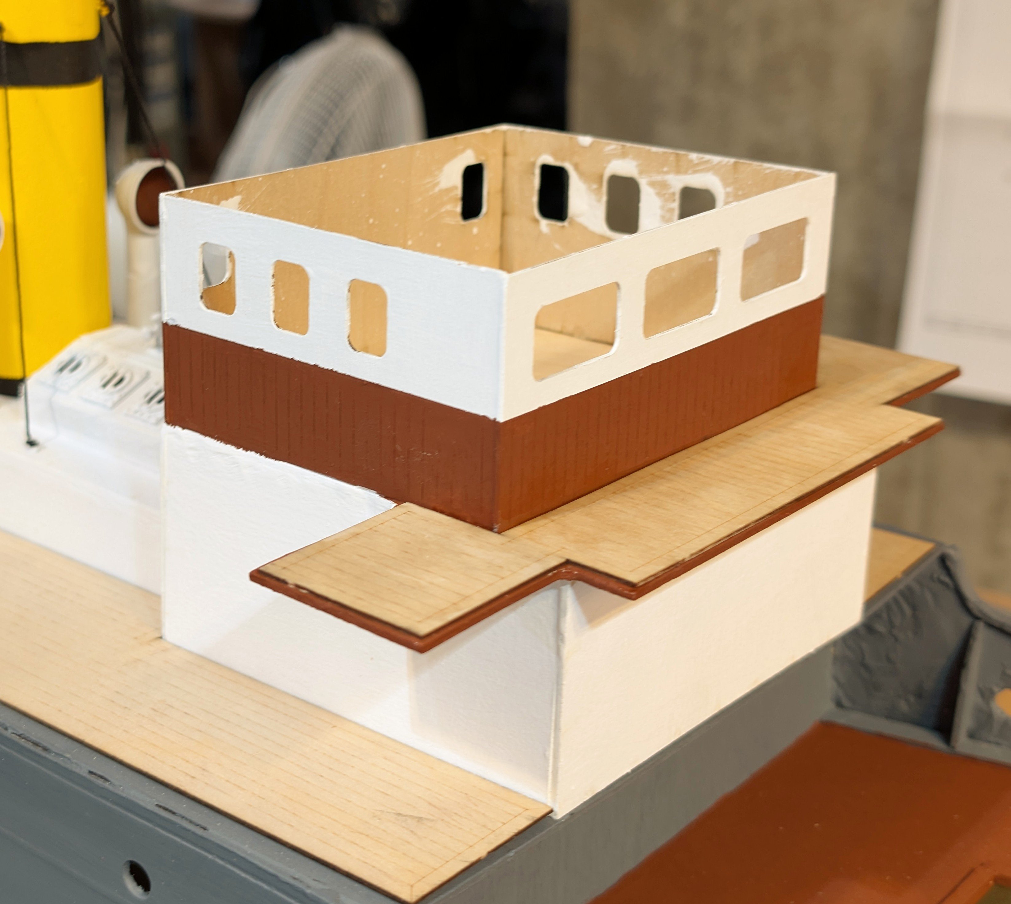
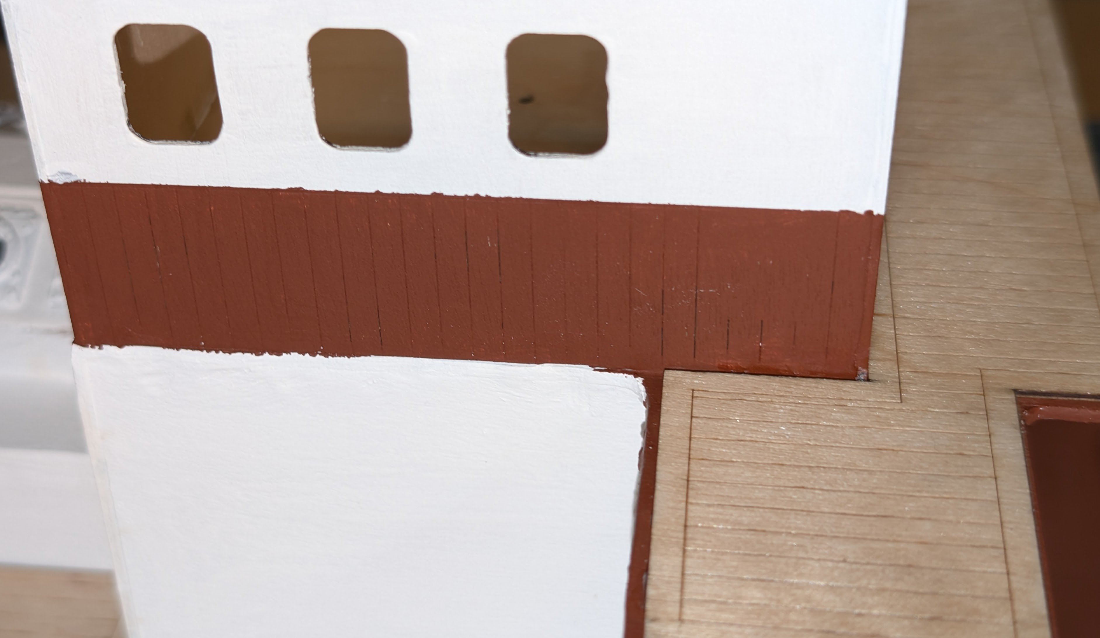
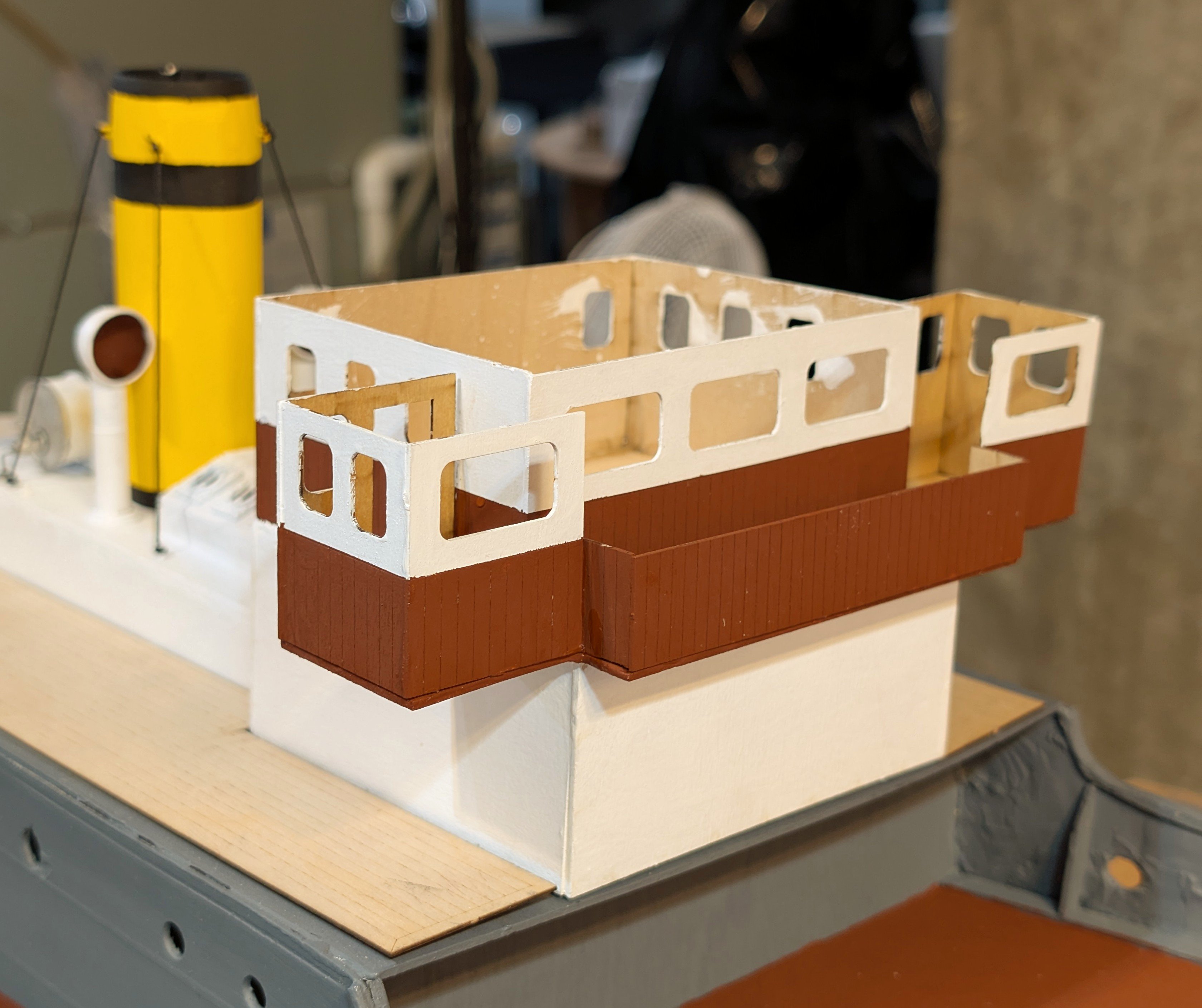
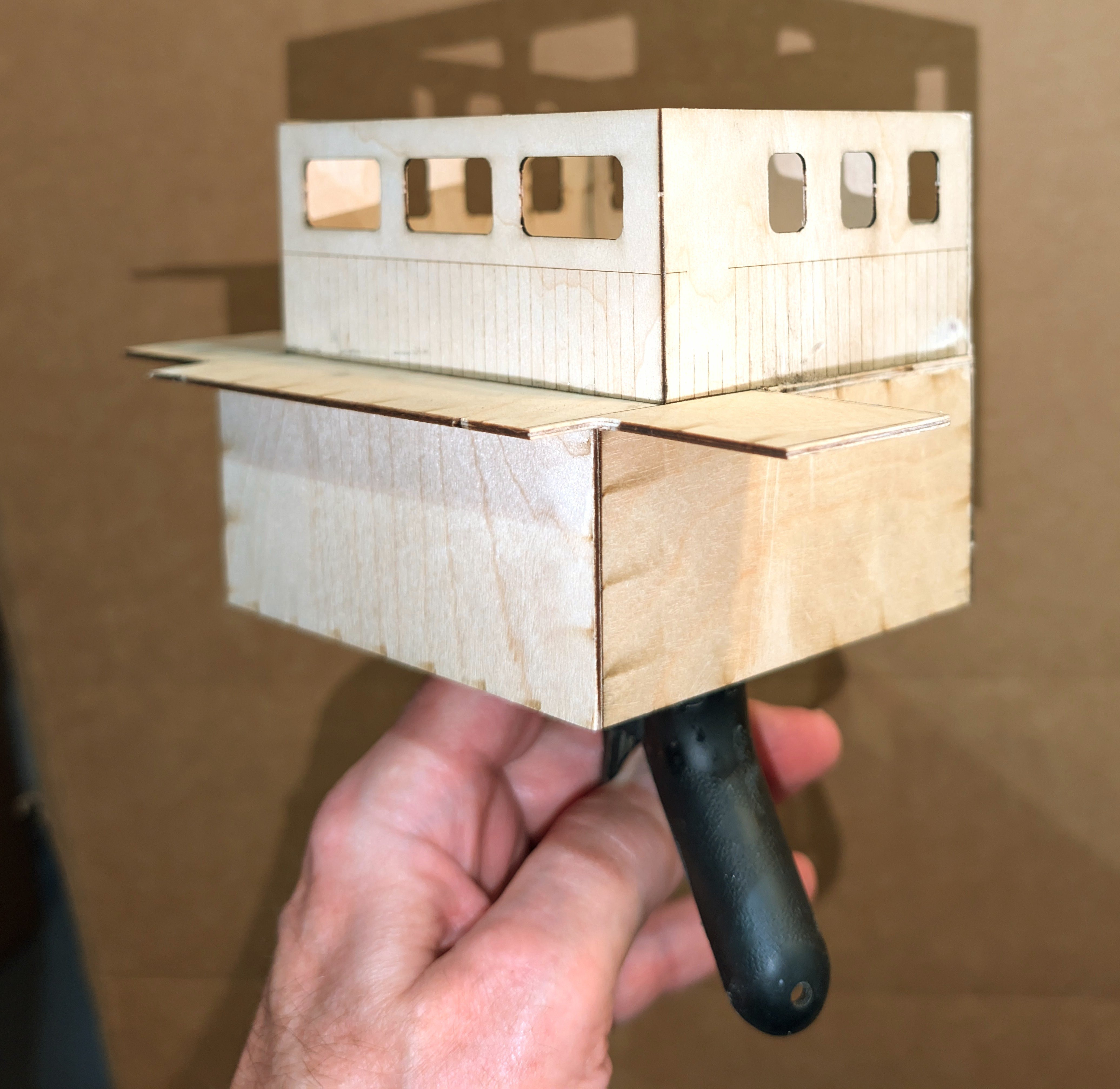
Getting ready to paint the bridge and wheelhouse structure. The issue is that the middle horizontal section is oversized. So I built all the structures, glued down the central top structure (which you can see in the pictures, built the side structures and bridge railing separately, and then dry-fitted them along with the pre-planked deck to figure out how far back to sand. Took some time.
All you see here is the lower part with the horizontal section, and the upper center structure glued on.
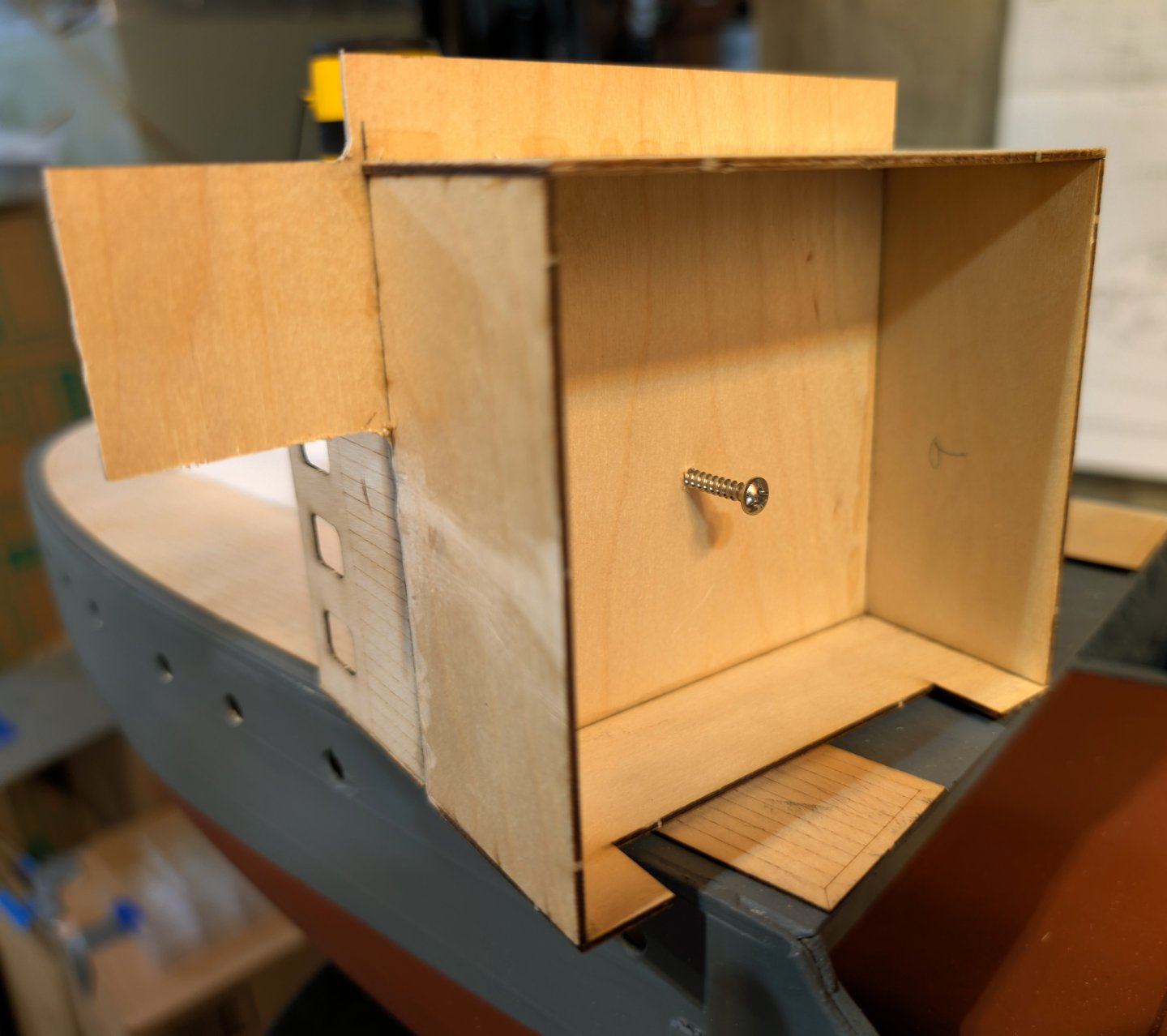
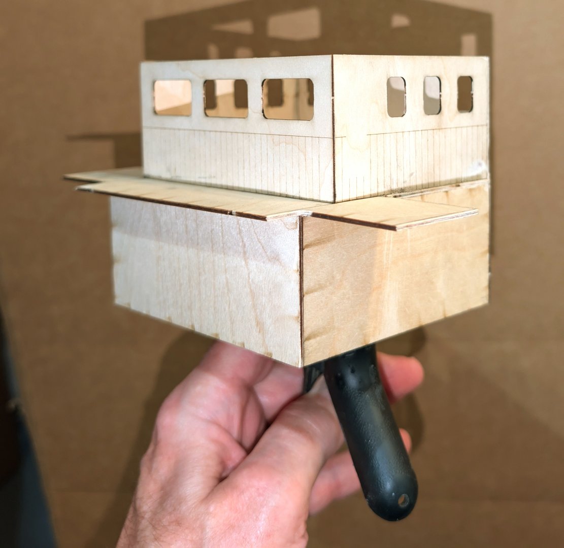
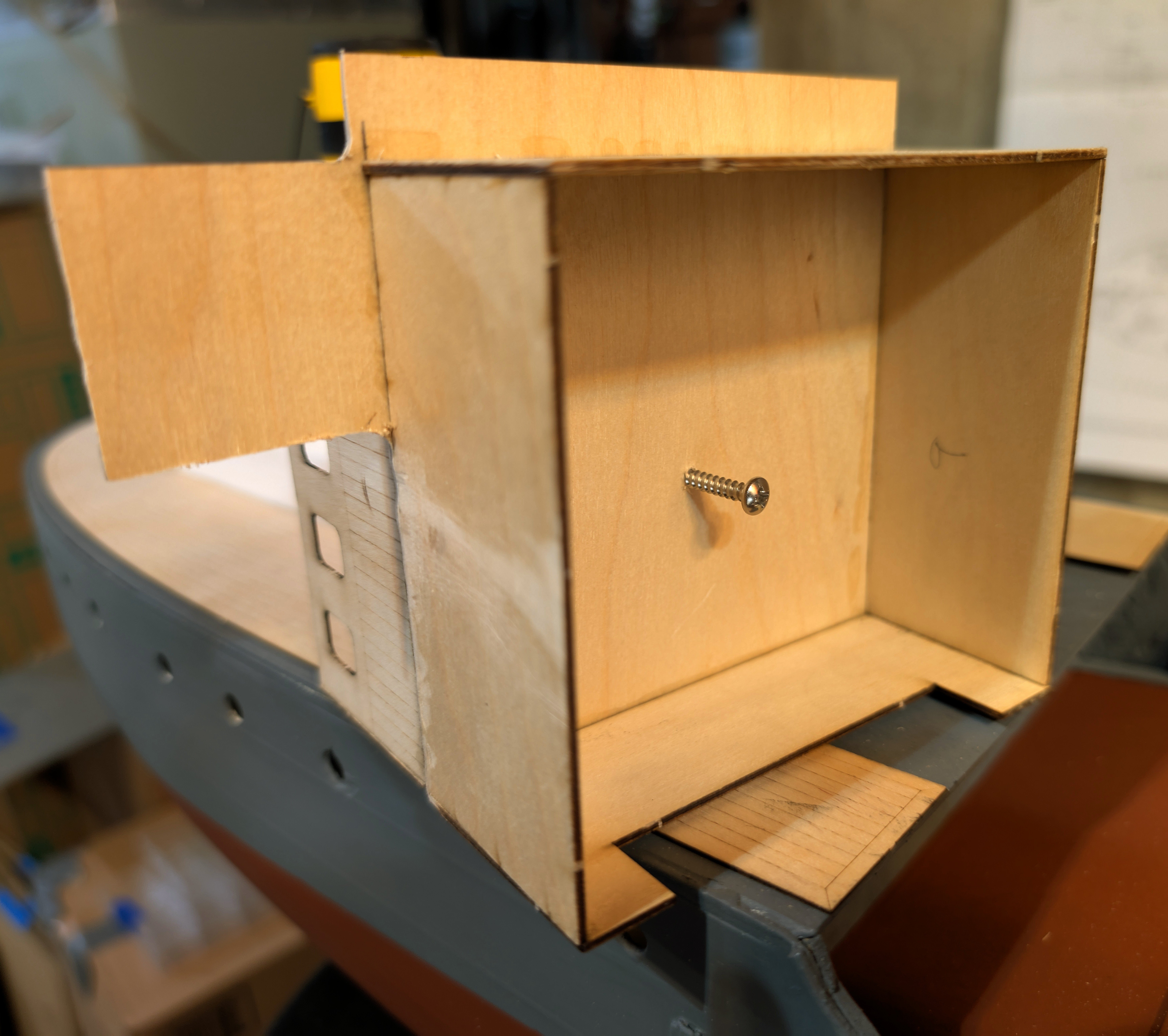
Next step is to paint, and to make that easier, I installed a screw underneath and attached a clamp to it so I can hold the whole thing and paint the sides in one pass. White first, then red-brown, then install the deck and varnish it, then paint and install the sides and railing. At least that's the plan.
Regards,
David
- yvesvidal, Landlubber Mike, gsdpic and 3 others
-
6
-
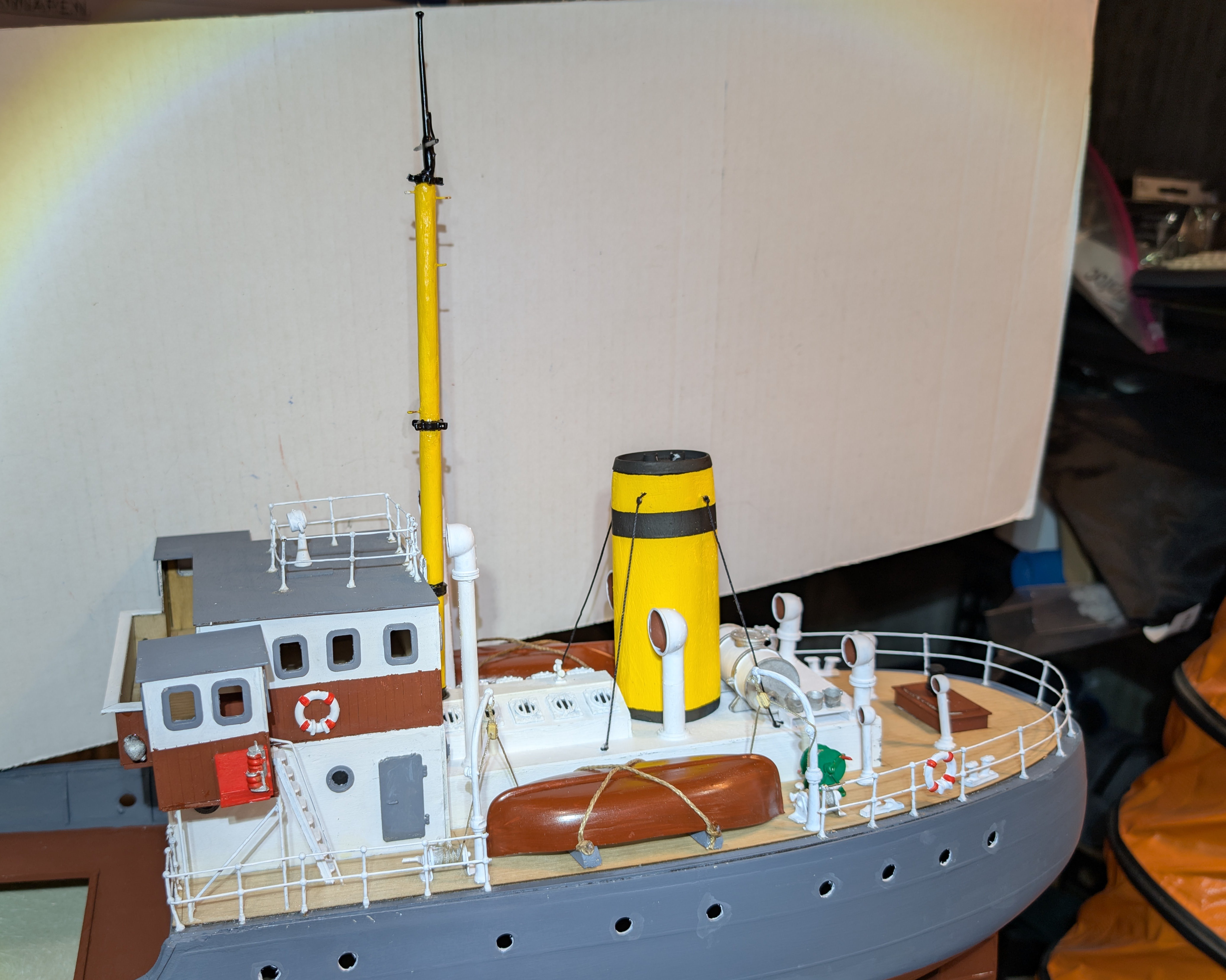
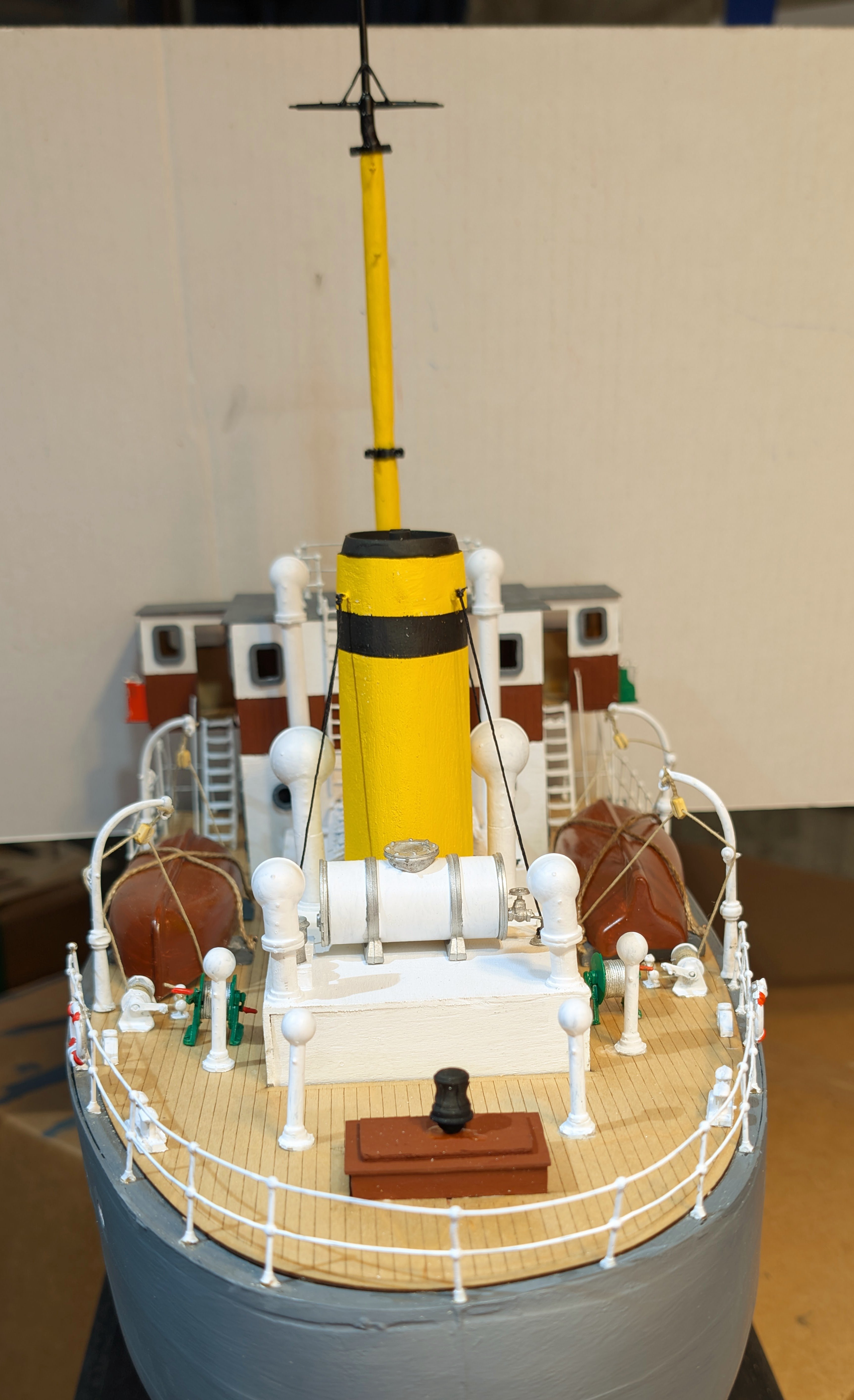
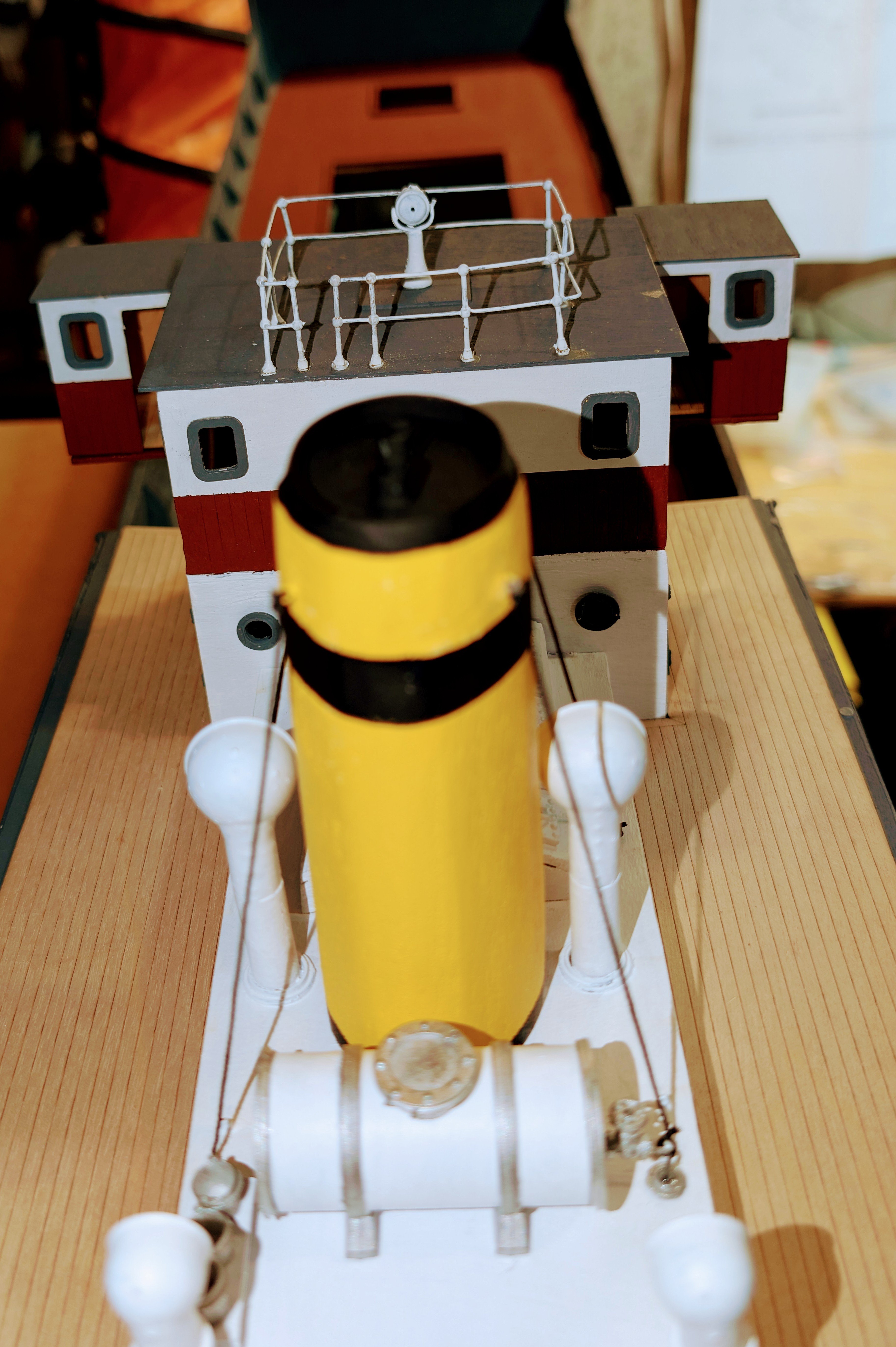
I finished up the sternmost structure, and it's shown here in position on the ship. What's not yet on it are a mast and two forward funnels, which need the adjacent structure for support.
Regards,
David


-
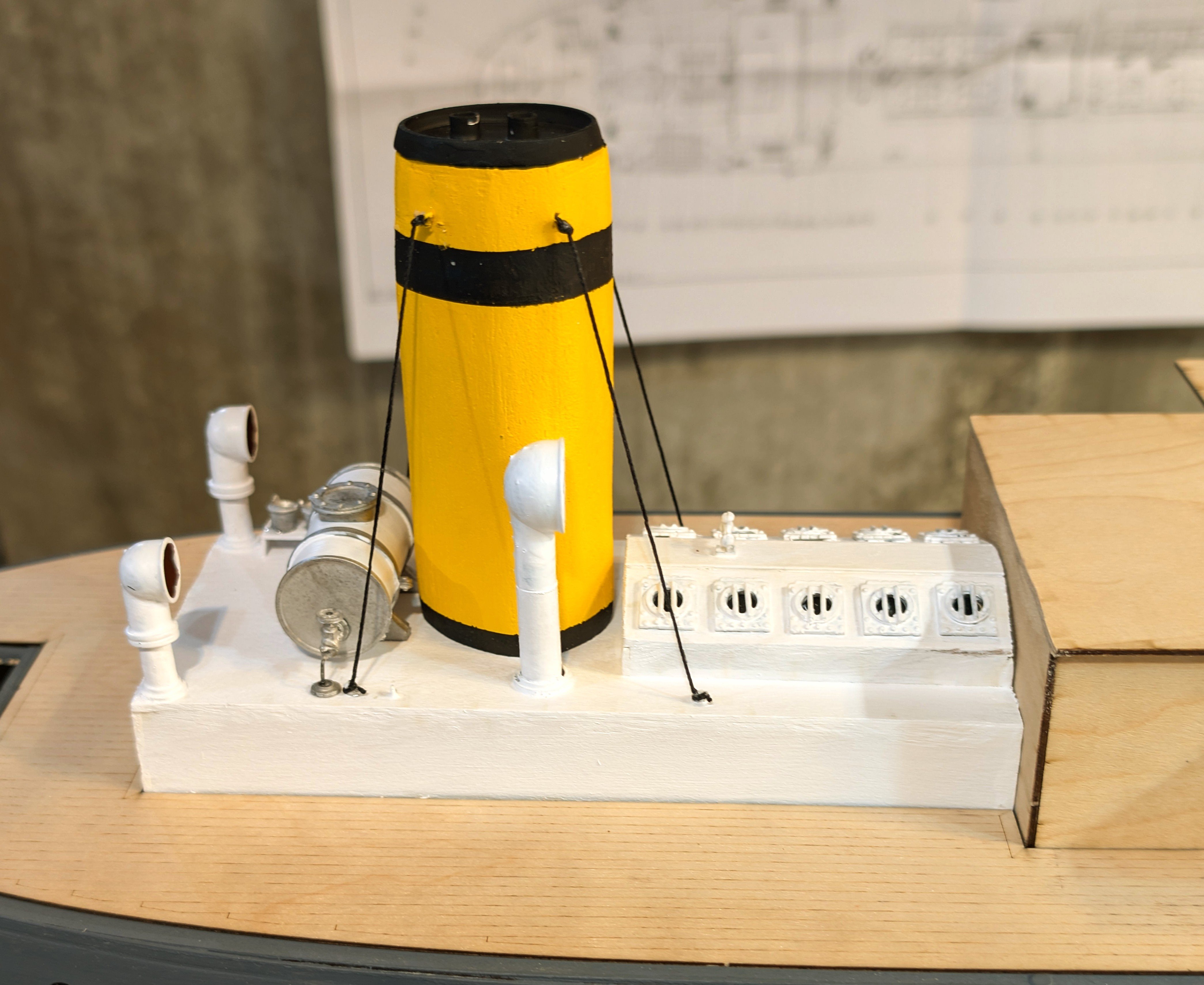
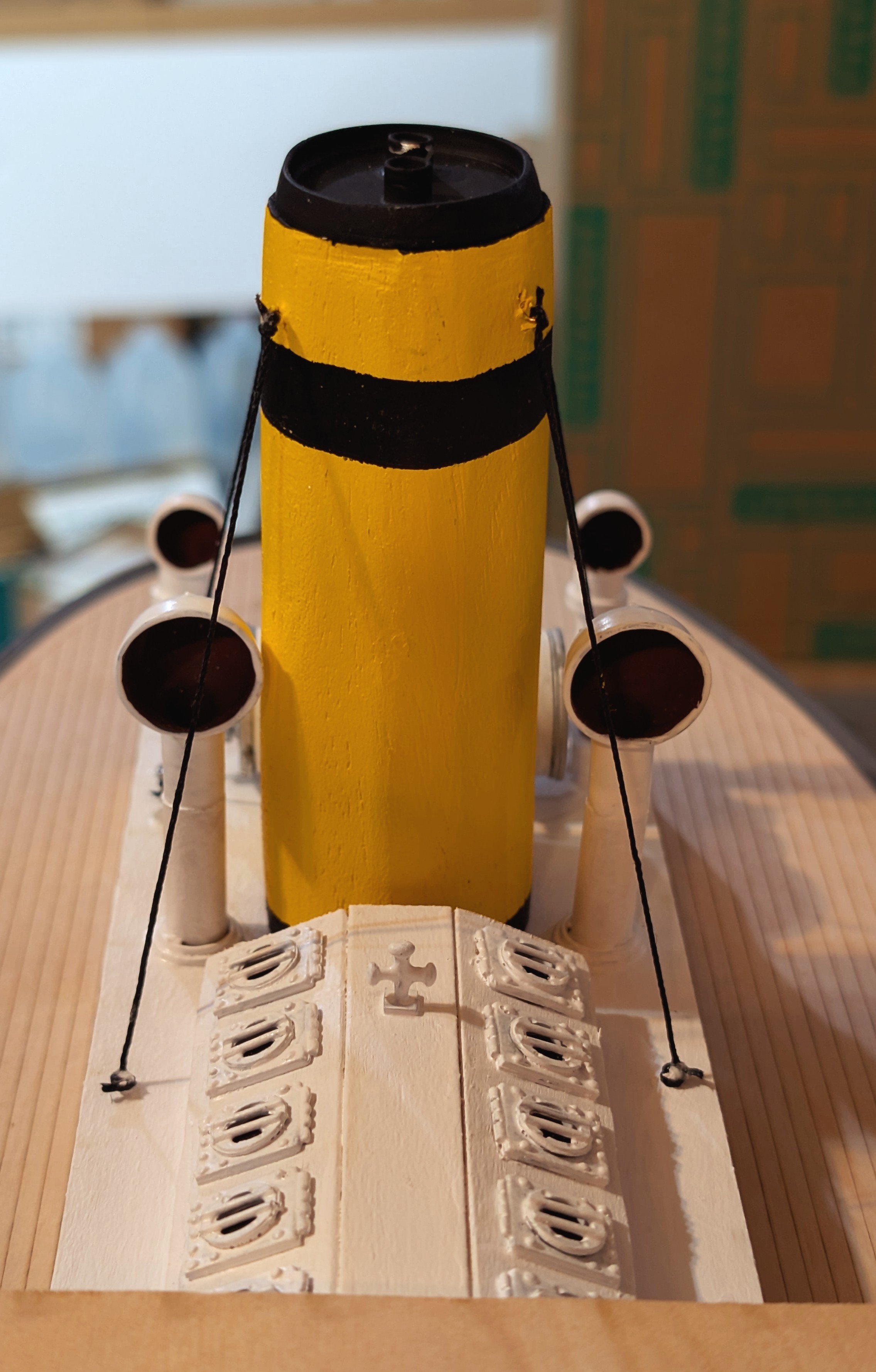
Here's an in-process pic of one of the stern structures. I'm also working on the main stack, which is an oval but had to be shaped from a larger block of wood supplied. Had to brush up on my whittling skills. 😁
Regards,
David
- king derelict, Nirvana, yvesvidal and 3 others
-
6
-
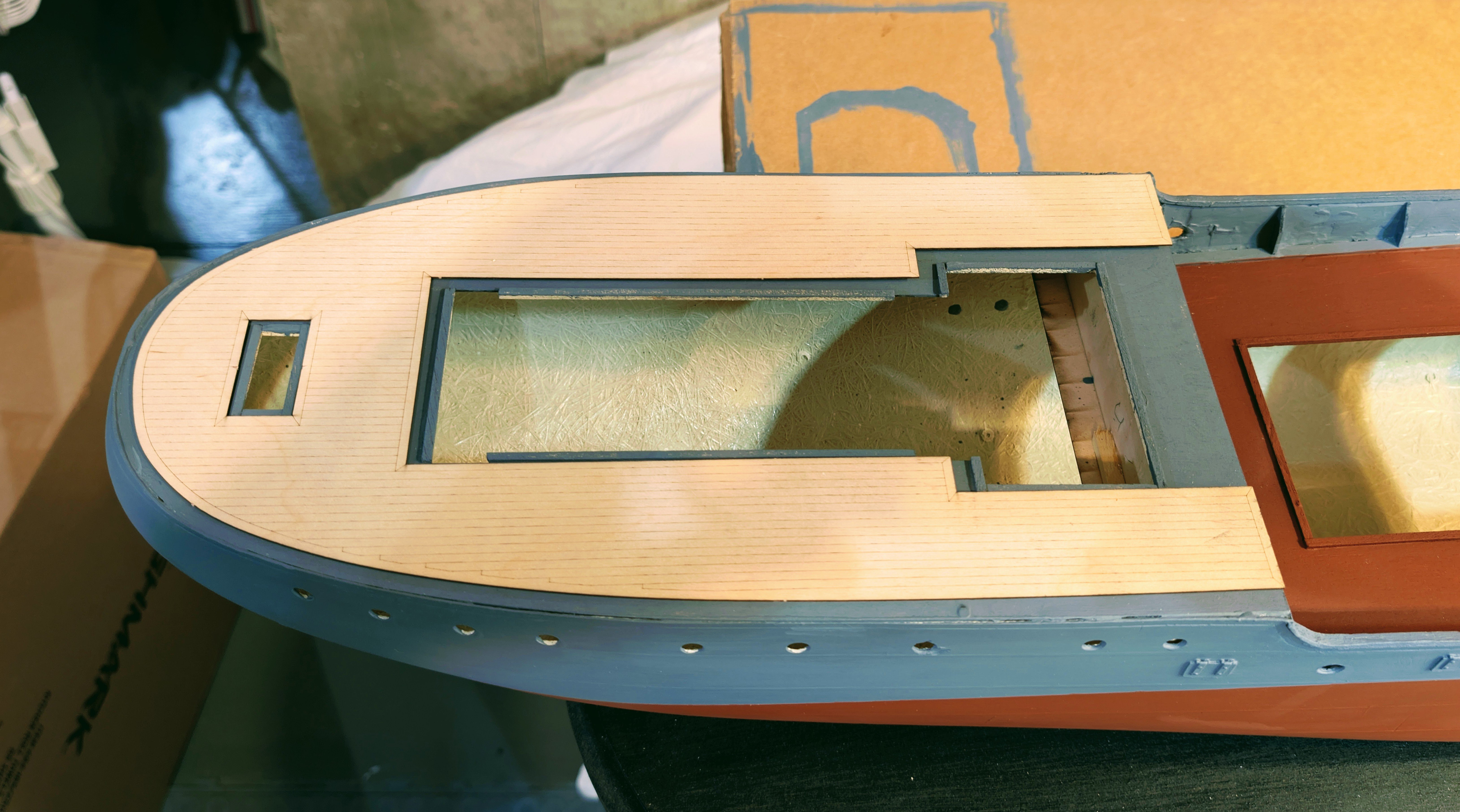
Started on the superstructure. I started with the stern because I wanted to figure out the interaction between the deck overlay (which has simulated planking), and the structures. Glad I did, because I had to sand down one end of the lower structure to make it all fit -- but it does fit pretty well. The structures fit nicely between the overlay and the hatch coamings.
By the way, I've discovered that for the hatch coamings you are supposed to use a thinner, wider wood that would create a better water-resistant fit, but I'm happy with these since I'm building a static model.
Now I'll move on to fit out and paint these structures.
Regards,
David


-
-
-
Started painting the hull. Here are the bulwarks, rear deck, forecastle deck, and top part of the hull painted gray. The rectangular spaces at the bottom of the gray paint on the hull are where I had small tape strips to guide me on how far down to paint to get past the waterline.
I'm going to approach the rest of the hull as follows:
1) Next, I'm going to paint the base. Usually I wait until a ship is finished before mounting the base, to protect the base from construction dust, but this ship has a large flat bottom that doesn't fit well in my foam cradle, and I don't want to paint it and then mar it by letting it sit flat on my workbench while working on the rest of the ship. So after I paint the rest of the hull, I'll mount the base and then wrap it in plastic to protect it.
2) After painting the base I'll paint the main deck. This will give the gray on the side of the hull more time to dry well before I tape the waterline.
3) Then I'll tape the waterline and paint the rest of the hull.
4) Finally, I'll mount the base.
Regards,
David

- Jim Lad, egkb, justaguyinvegas and 4 others
-
7
-
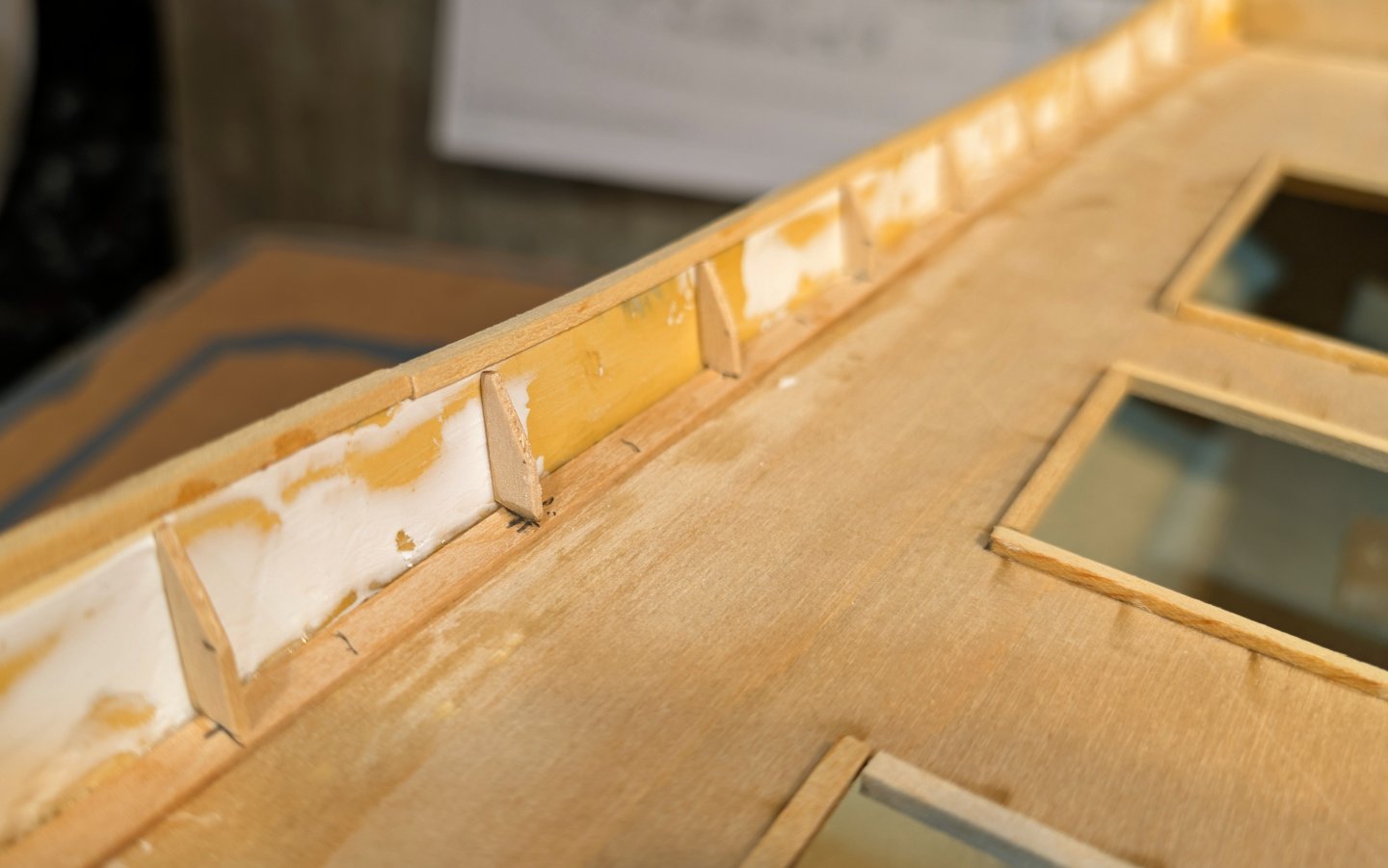
Something I meant to comment on above is the direction in the instructions to use scrap plywood for the bulkhead supports (and also for the part of the capping rail that curves).
For a kit that cost me $600, I found this pretty annoying. Caldercraft should have included a couple of pieces of strip wood for the bulkhead supports. Instead of scrap ply, which would be difficult to make uniform, I went to my stash of leftover wood from previous models and got some strip wood that fit. Still "scrap" in a way, but a better option.
Regarding the curved part of the capping rail, the instruction was to use scrap ply cut across the grain so it would bend, and fair it into the rail. I elected to use my steamer on the capping rail and bend it.
But again, the idea of going to scrap wood isn't consistent with the price of the kit, or with Caldercraft's quality on, say, HMS Victory. I was surprised.
Regards,
David
-
Mounted the washport covers on the outside of the hull. Also made and mounted the bulwark support frames. The base plate where the bulwarks meet the deck is not called for in the instructions, but it's on one of my pictures from the internet and I think it really dresses that junction well.
Now, on to painting the decks and hull.
Regards,
David


- Landlubber Mike, Jim Lad, yvesvidal and 4 others
-
7
-
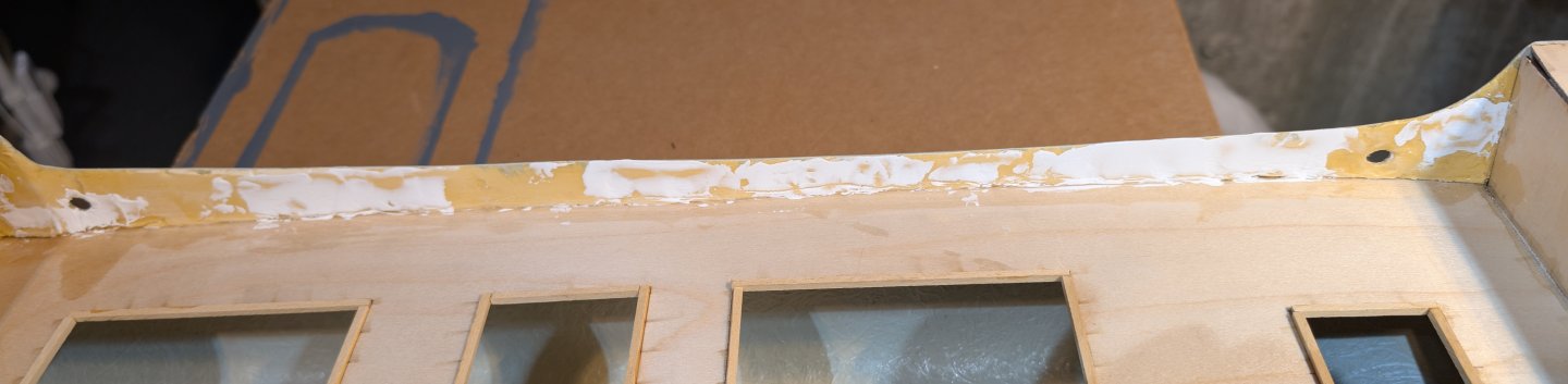
The inside of the fiberglass hull is rough with fibers running across it, so you have to use filler on the bulwarks to smooth them out. This looks messy but the sides are now smooth inside. It's the product of a three-step process: first, wood filler. Then, two coats of varnish. Finally, putty in the remaining craters and imperfections. Then sanding with 220 grit followed by 600.
Regards,
David
- Landlubber Mike, egkb, gsdpic and 1 other
-
4


Brannaren by drobinson02199 - Caldercraft - Scale 1:48
in - Kit build logs for subjects built from 1901 - Present Day
Posted
Fo'c'sle now finished. On to the boom.
Regards,
David