drobinson02199
-
Posts
1,079 -
Joined
-
Last visited
Content Type
Profiles
Forums
Gallery
Events
Everything posted by drobinson02199
-
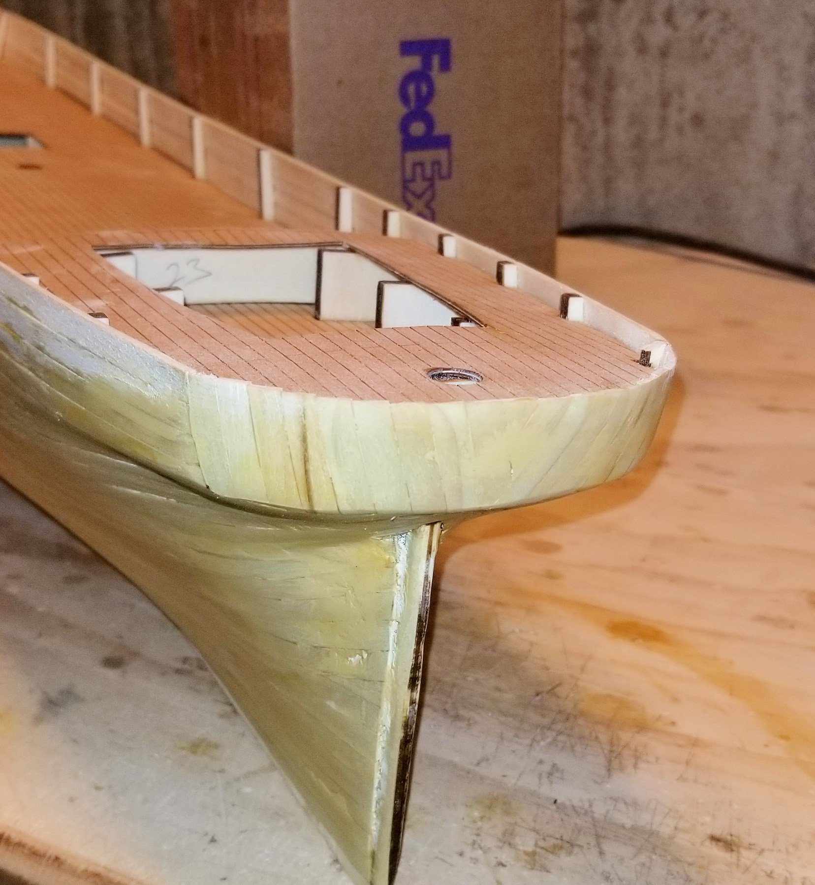
 HOF: Thanks -- the YouTube videos were really helpful. He's using very thin plates -- mine are the thicker kit plates so I don't have the same flexibility he does. Two big things I took out of the videos: The idea of end-capping the cutwater, stern and keel. It's given me a new thought on how to do that on my model. I'm reflecting on his approach of doing the waterline with a row of plates and then using cut plates in the middle to finish off. I was going to trim plates to fit at the waterline. On reflection, I think his way will work better and so that's what I'll do. I'm using medium glue all the way, and it's working pretty well. I'll post a shot when I get a bit further along. Regards, David
 -
Hof: 2,500 plates? I'll be finishing the coppering with a glass of egg nog. 😛 Regards, David
- 133 replies
-
- 2
-

-
- cutty sark
- mantua
- (and 3 more)
-
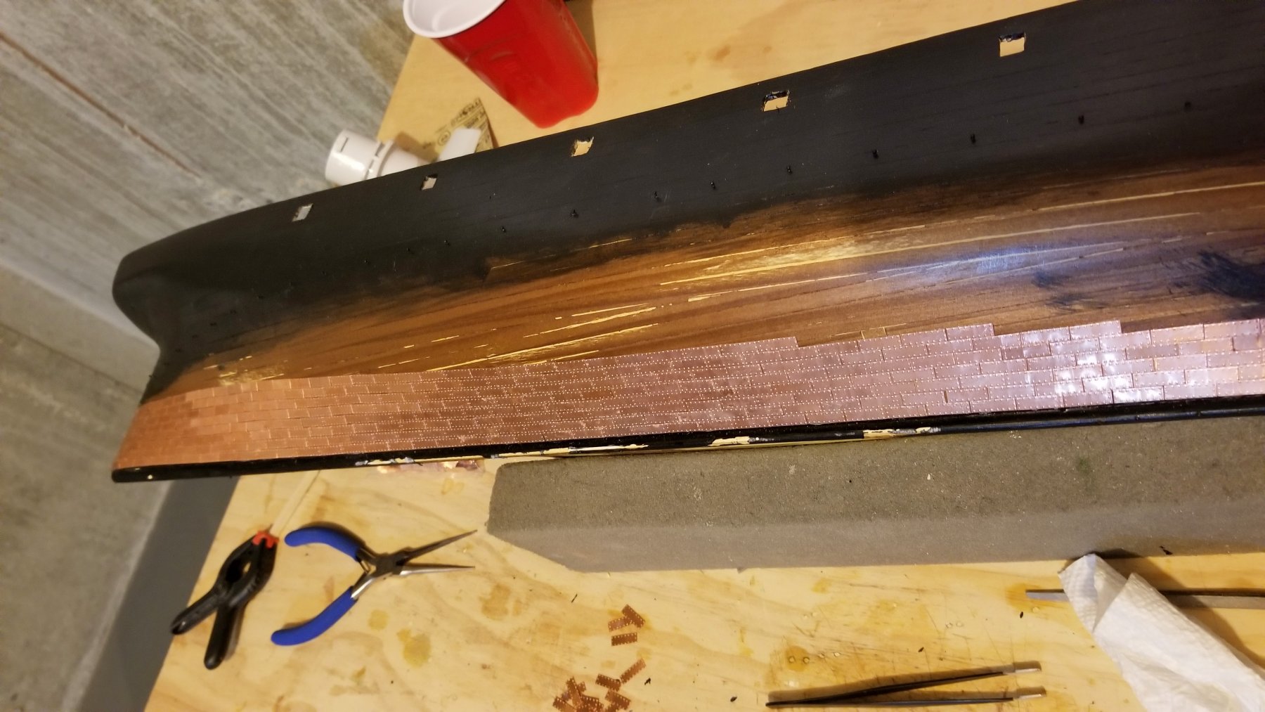
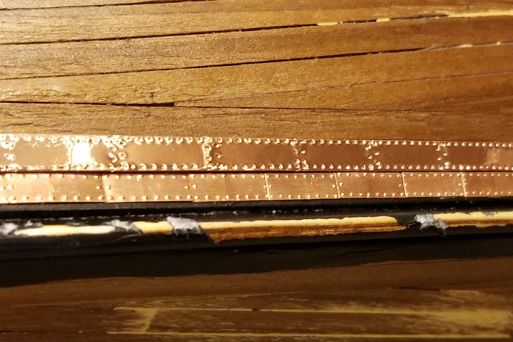
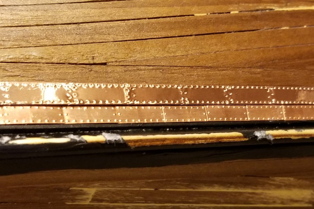
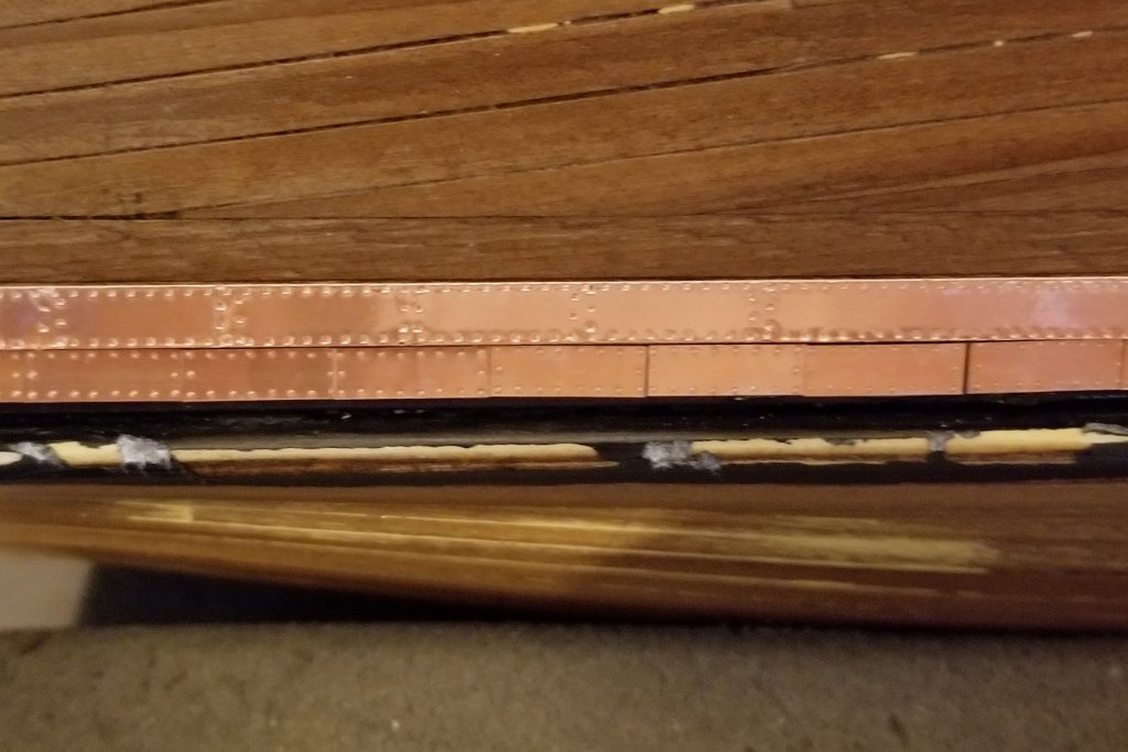
Here's why I abandoned the tape. I made up a strip of the copper tape and put it above a row of the real plates that I have started at the keel. It's really hard to get good shots of this because of the way the tape and plates reflect light, but you can see it in these two pics. The pounce wheel does a fair job of making rivet marks at top and bottom, but the divider rivets just don't look right -- AND, the tape is really shiny compared to the copper plates. Regards, David
- 133 replies
-
- 1
-
-
- cutty sark
- mantua
- (and 3 more)
-
Change in direction. I tried my first piece of copper tape, and it just doesn't look right compared to the copper plates supplied with the kit. The impressions made by the pounce wheel are uneven, and the tape is too shiny. So it's on to individual plates, and I'll probably be at that for a while. Regards, David
-
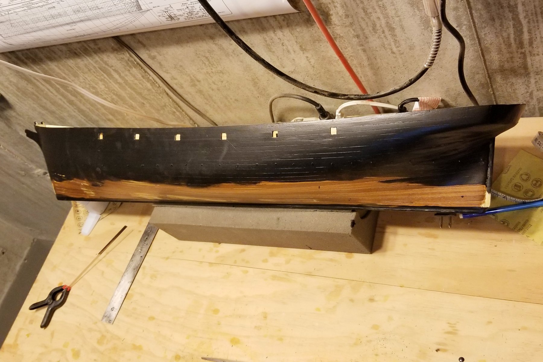
Have now painted the upper part of the hull black. I brushed on the paint vs. spraying. If I spray, I get spray mist all over my workroom (even with major plastic dropcloths) and have to be super careful not to track it into the house. Just a mess. I have a small exhaust fan mounted high, and maybe I'll get motivated and buy some flexible ducting to bring the exhaust down to the spray area I use. But I used a foam brush here and it worked fine. Time to start coppering. I'm going to see if I can make copper tape work. Stay tuned. Regards, David

- 133 replies
-
- 6
-
-
- cutty sark
- mantua
- (and 3 more)
-
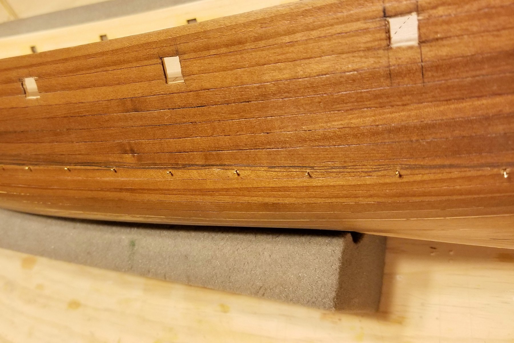
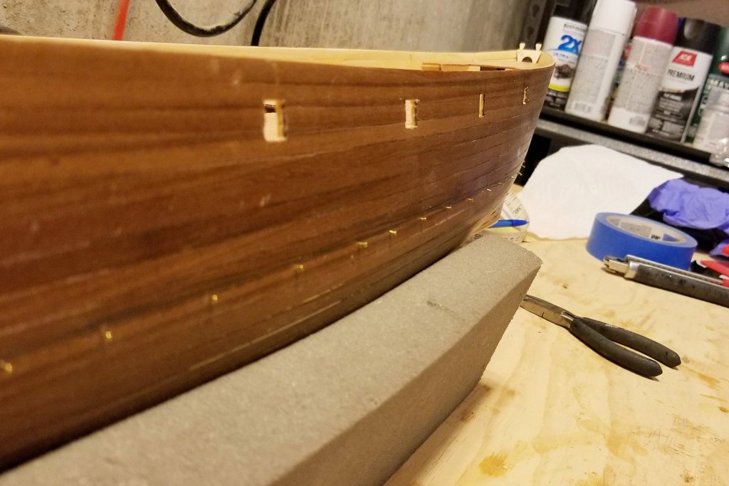
So here's my plan for painting. I don't want to paint the lower part of the hull, because I've read that paint can be a poor surface for coppering. So as shown in the pics below, I have put pins in the hull just about 1mm below the waterline. I'll leave them in and paint down to them only. Then when I copper the hull, I'll come up to them and use the holes as a guide for the last copper row, which will cover the holes. Anyhow, that's the idea and we'll see how it works. Regards, David

- 133 replies
-
- 4
-
-
- cutty sark
- mantua
- (and 3 more)
-
All ports cut now, and ribs removed from inside bulwarks, so now I'm ready to paint. Regards, David
- 133 replies
-
- 3
-
-
- cutty sark
- mantua
- (and 3 more)
-
Harry: By "facimilie" for the ports, do you mean the port covers? If so, yes, there are brass ones with tabs. What happened when you didn't anneal them? Did they snap off? I've realized that this will be along build -- but that's OK. Regards, David
-
Harry: Yes, the brass bulwarks would have been a help as I have to be really really careful. No need for template as I can take spacing and measurements from the drawing, but just need to be really careful when cutting them out. The ports don't hit any of the bulwark extensions, so no sequence issue there. And yes, those strips are rubbing strakes. So much for my nautical vocabulary. 🥴 Regards, David
-
I've finished the second planking now and have applied 3 coats of varnish, but . . . The instructions puzzle me, because they call for finish painting of the hull, coppering, and applying decorative wood strips to the outside before cutting the ports and sanding the inside bulwarks. That seems to me to be a prescription for messing up the hull work. So I haven't done the final sand on the varnish or painting or coppering yet, and as you can see I'm cutting the ports now. Tough to get those square and lined up with each other. Then I'll remove the ribs and sand the inside bulwarks, and THEN I'll paint it and copper it. I'm only going to paint down to just below the waterline, so that the coppering (for which my plan is to use tape) will have a better surface to adhere to. One of you who has done the Cutty Sark before will likely tell me that I've made a serious sequence error, but it doesn't seem like it. Just another "look ahead" lesson. Regards, David

- 133 replies
-
- 5
-
-
- cutty sark
- mantua
- (and 3 more)
-
I really appreciate the recent comments of appreciation -- but something odd must have happened on the website to create a notification, because I finished this ship last September. Nevertheless, thanks all! Regards, David
- 126 replies
-
- 2
-
-
- fly
- victory models
- (and 1 more)
-
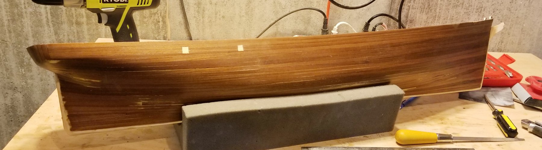
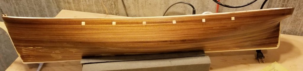
First planking completed. I'll probably finish sand this once more and varnish again. The curved stern, which is made up of vertical plank slats, came out better than I thought it would looking at the rough slats before sanding. Regards, David

- 133 replies
-
- 7
-
-
- cutty sark
- mantua
- (and 3 more)
-
Hof: My kit has the flat rail stanchions, and I think I'll live with those. Are the brass bulwarks specific to the Cutty Sark? Mantua has an extensive UK site (I think it's a distributor, but a lot of fittings) and the bulwarks aren't there. in the fittings section or the Cutty accessories. Thanks for the Mantua email -- I'll think about getting those. Yes, I am going to copper the hull, but after doing some research and reading about plates popping off, I am going to go with copper tape, onto which I will emboss rivets with a pounce wheel. I think it should make the coppering go a bit faster. Regards, David
- 133 replies
-
- 1
-
-
- cutty sark
- mantua
- (and 3 more)
-
Snowy: I have cans of compressed air and I use that on the ships and the rigging about once a month. Regards, David
- 133 replies
-
- 1
-
-
- cutty sark
- mantua
- (and 3 more)
-
Chris: I don't use display cases. I have them on track-mounted shelving in my office, which allows me to adjust shelf height as I go. When I run out of space, I'm going to put up shelves in my workroom and move my least attractive models there. Right now in my office, I have six on one wall with room for probably four more, three on another wall with room for possibly two more, and another wall where I could get 4-5. The Titanic is mounted over my flatscreen TV. Regards, David
- 133 replies
-
- 1
-
-
- cutty sark
- mantua
- (and 3 more)
-
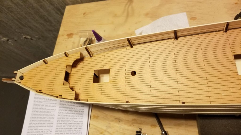
Henrik: You're right -- the deck pattern is printed on the deck plywood (see picture below). And it's not a stupid question. When I first saw the decks, I thought "oh, maybe I don't have to plank them." But then I looked ahead and yes, you do have to plank them. So I'm not sure why Mantua did this, but I suppose it's a good guide to get an even deck pattern. Regards, David
- 133 replies
-
- 5
-
-
- cutty sark
- mantua
- (and 3 more)
-
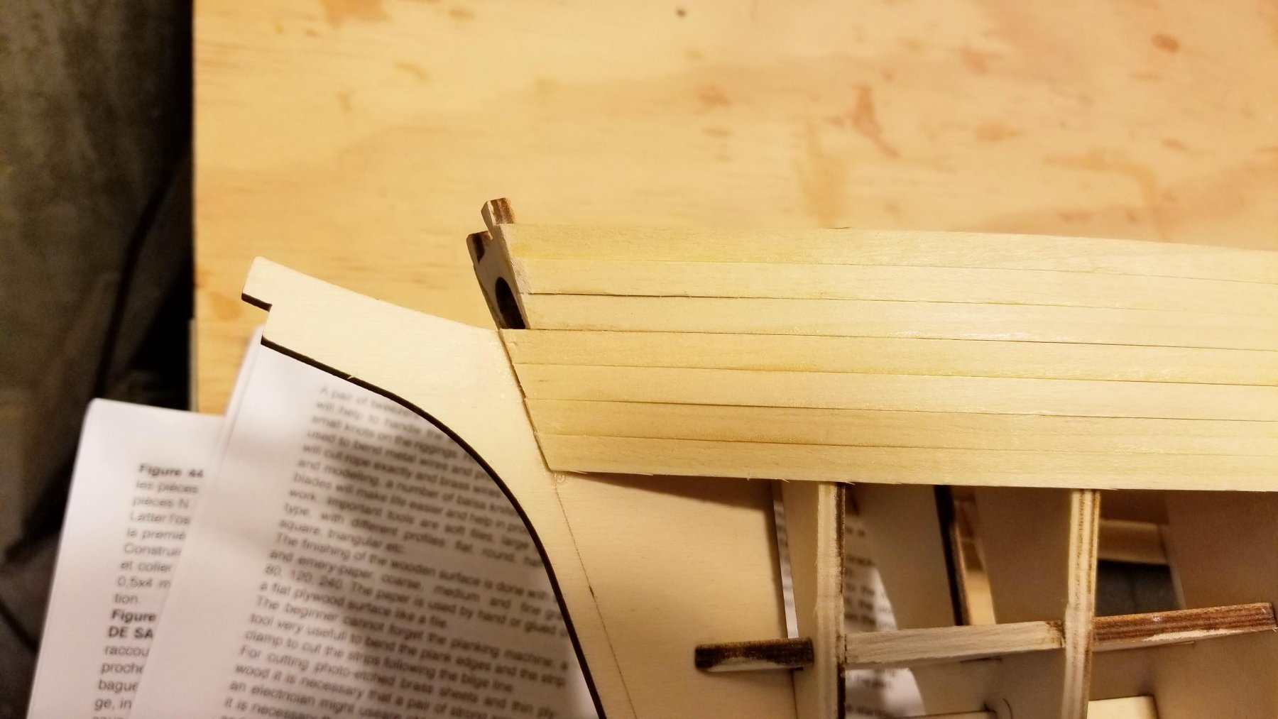
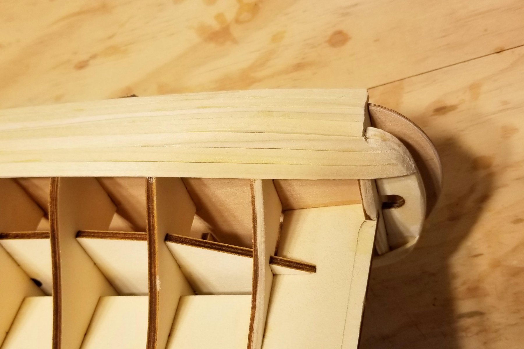
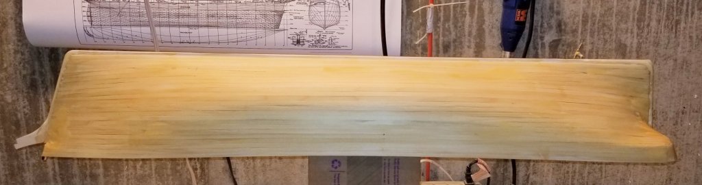
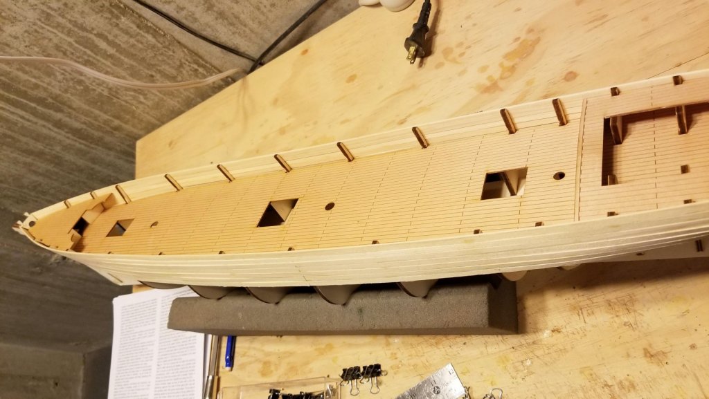
A progress report on the first planking. Going very smoothly so far. Using my steamer at the stern. Pictures below. I'm making slow progress as I am gluing the planks in segments to be sure of a good fit, and I'm letting the glue dry for each segment. One thing I noticed reading ahead is that the frame ribs will all be removed above the decks. If you look at the picture of the deck, the bulkhead that will be left is very long, and I was concerned about its integrity. So I glued the planks not only to the frames, but to each other along the entire edge. I was only going to do the edge gluing for the portion above the deck, but have continued further it as it seems to produce a smoother hull. This is the first time I've done the edge gluing, and I'll now always do it, but I'm curious if it's actually a standard first planking technique and I'm just catching up. Do others of you do that as "standard"? Regards, David


- 133 replies
-
- 9
-
-
- cutty sark
- mantua
- (and 3 more)
-
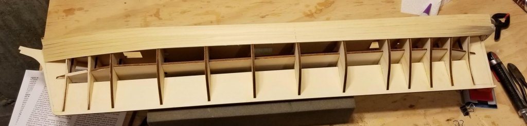
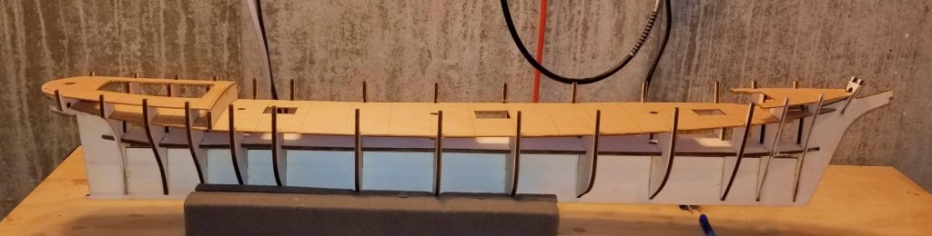
Hull structure completed, frames tapered and ready for first planking. Picture attached. This is my first Mantua kit. The materials quality appears to be very good -- the frames and keel went together perfectly. The instructions and plans sort of skim things at a high level, however, so I'm glad this wasn't my first (or even my third) kit. Lots of interpretation and prior experience judgment needed. Regards, David
- 133 replies
-
- 5
-
-
- cutty sark
- mantua
- (and 3 more)
-
Thanks, HOF. I found them online and ordered both the general and rigging plans. Regards, David
-
Hof: Not aware of "Campbell's Plans". What are they and how would I get them? Thanks for the heads up. I have just started -- one of my planned steps is to look for previous build logs to see what people had to work through. Regards, David
-
Chris: She's 1150mm long -- a bit over 45 inches -- so a big one. Regards, David
- 133 replies
-
- 1
-
-
- cutty sark
- mantua
- (and 3 more)
-
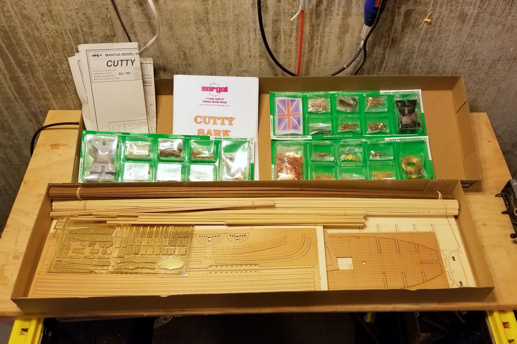
Beginning a new one after a short break. Here's the "what's in the box" picture. This is my first Mantua kit, and I'll be interested to see differences from other kit makers. One thing I've noticed is that plans are printed on both sides of the paper, which may turn out to be cumbersome (vs. just posting them up on the wall). Regards, David

- 133 replies
-
- 3
-
-
- cutty sark
- mantua
- (and 3 more)
-
She's a beautiful build, Chris. Regards, David
-
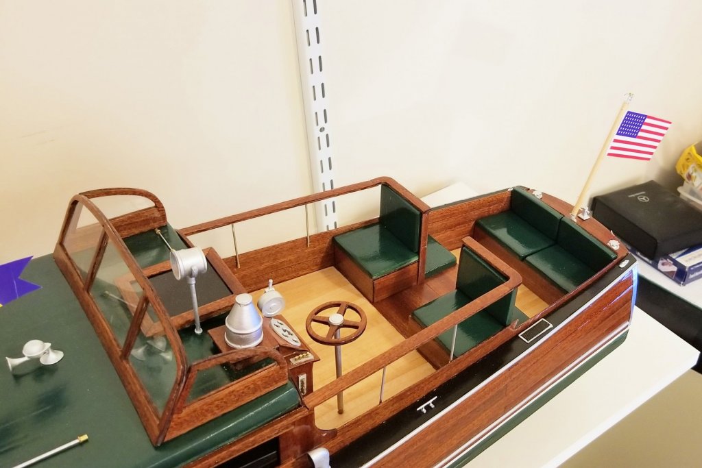
COMPLETED! Here's a single picture showing the seats. Full completion pictures of the boat are in the Completed Kit-Built Gallery. It's been a fun build. Regards, David
- 49 replies
-
- 10
-
-
- dumas
- Chris-Craft
- (and 2 more)