
Supplies of the Ship Modeler's Handbook are running out. Get your copy NOW before they are gone! Click on photo to order.
×

Captain Slog
-
Posts
904 -
Joined
Reputation Activity
-

 Captain Slog got a reaction from cog in Borodino by Captain Slog - Dom Bumagi - 1:200 - CARD
Hi all,
I am still holding off from skinning the hull until I have a solid block of time to work on it without interruption…well that’s my excuse and I’m sticking to it.
So to keep moving forward I decided to do the propellers. Borodino has twin, 4 bladed props and these consist of the hubs, end caps and the blades. I thought these would be good to show as they have 3 typically encountered card modelling techniques; these being laminating, forming cones and forming curves using multiple petals.
The photo shows all the parts rough cut out to make 2 props.
First up are the end caps. Even without diagrams you know a circle with a segment missing is going to form a cone. The technique here is to use a rod of some sort to form the cone; the smaller the part the thinner the rod needs to be, in this case due to the tiny size I used a sewing needle.
I do this by placing the part upside down (obviously) on the pad of my finger (you could use the heel or palm of your hand; it depends on the size of the part and the amount of curve) and then pressing the needle down on the part and rotating the needle around the apex of what will become the cone.
You need to press against something soft with give so the part bends against the needle. Start gently until you get a feel of the amount of pressure needed to slowly work the bend into the part. Don’t go hard at it in case you put a fold or crease in it.
Two important things to remember; always keep the point of the needle at the apex and at 90 degrees to the edge of the part to form it uniformly. If you have the needle at an angle the curve won’t be around the apex. Secondly you need to rotate the needle (or rod or whatever) as you move it around the outside from one side to the other. It doesn’t work so well if you ‘drag’ it around plus you’ll find the part may spin instead of bending round the needle.
You could keep going until the edges are near enough together but I find the part starts to get overworked and edges start to soften and delaminate etc by the time this stage is reached so get it close enough.
Once I think it is ready to glue I try holding it in different ways using fingers, tweezers etc and try and work out the best way to glue it without needing three hands and double jointed fingers; only once I think I am am comfortable will I apply the glue. In this case I held them between finger and thumb on one hand and used tweezers in the other to manoeuvre and hold the edges together.
The finished end caps. I am actually pretty happy with these and although the macro shows a thick black seam (I cut outside the line ) the size of the caps are only a few mm and the seam is a thin line at normal viewing distance.
Also a trick to remember is where to place your joins and seams when assembling the model. If multiple parts with many seams make up a larger assembly if possible align these together away from view as much as possible.
I this case I will align the seam of the end cap with the seam of the hub and in turn align the hub seam with the propeller shaft seam made previously. Then when installing in the hull I will fit the whole lot with the seams turned down and in towards the hull so it would be virtually impossible to get an eye in to see any joints once the model was complete and on a baseboard.
Next up will be the hubs.
Cheers
Slog
-
Captain Slog got a reaction from cog in Borodino by Captain Slog - Dom Bumagi - 1:200 - CARD
Hi all, thanks for the comments and likes.
A bit of progress this weekend. Firstly I managed to finish off all the hull fairing; in particular the top deck section. The sides of the hull on this section are curved with the curve continuing down to the deck below. Because the laser cut forms are square edged these needed to shaped to suit.
The object is to leave the bottom edge intact and bevel the former ends to the curve. I knocked the top edge off free hand with a craft knife and used a sanding block I made up years ago for something else.
It consists of 2 pieces of 20mm wood quadrant glued together and has 400 and 240 grit sandpaper stuck on with contact adhesive. I chopped the quadrant to suitable sized lengths. As can be seen in the photo their a near perfect fit for sanding the decks to match the hull curve.
The top section won’t be glued to the rest of the hull until the lower skins are fixed; there are a couple of sticking up parts which would get damaged when skinning the underside. Also the anchor shelves need to be skinned before fitting the top section. I spent a fair bit of time studying the plans and the parts and have finally worked out how the shelves are made up.
After Chris’s comment about spraying the parts with matt spray I obtained Boyle Matt Spray Acid Free Clear Finishing Sealer from the local hardware store. I sprayed all the red lower hull skins with 3 coats. I haven’t done much to confirm it’s suitability doesn’t seem to had any adverse effects and will be interesting to see how they handle.
One thing though was a part I sprayed already had cuts made in it and the pens I use for edge colouring had some trouble on a few edges. I just need to make sure I spray parts before cutting out in future.
Okay here are all the major skins cut out. The seven parts are all that’s needed to cover the lower hull. I think I would have preferred more smaller parts rather than fewer large parts. The 2 rear ones have lots of cuts to allow them to form over the tight stern and I wonder how successful I will be in that area. Also I mentioned previously that the skins butt together rather than overlap so less wiggle room with that method.
Here are the rest of the lower hull parts and include the propeller shaft bulges and supports as well as the props themselves. The lower part, K1 is the rudder and being a master procrastinator decided to build this next instead of continuing with skinning the hull.
I enjoyed doing the rudder, having something manageable to form and glue up. The one part is cut out and folded to shape. Along the top edge a strip of 1mm by 1.7mm(!?) card stock (scrap from the laser cut forms) is glued on and the tabs folded over to form the front edge of the rudder.
I am not sure but I think this card is slightly thicker than I am used to previously and suffers from the paper delaminating on small and bent parts. The tabs delaminated on folding over and I had to brush in PVA to fix. Also the small sticking up tabs form the hinge and these delaminated as well despite very little handling.
The instructions show a 1mm hinge pin so 1mm brass rod was laid between the tabs. I applied glue to the tab ends and folded over the rod. Whilst gripping the sides with my fingers I used the sides and edges of tweezers to work and form the tabs together. Periodically I would twist the brass rod so that it didn’t stick to the glue and could be removed and inserted.
The rudder bottom wraps round and up to close of the bottom hinge.
The completed rudder. It is not shown if the top and bottom strips fit between or on top of the rudder sides. I decided to fit them between for a cleaner side view but I actually think they should lie on the rudder edges as it was a bit tight getting them in there. There is still a small rudder shaft top (K2) to do.
I’ll know better when the stern skins are on but hoping I can form their hinges the same way and then insert the rod to join but not sure if this is possible which may mean trying to form the stern hinges round the rod with the rudder attached which is going to be a pain.
Cheers
Slog
-
.thumb.jpeg.fc5d633a7b34428fcf19419a73d56d55.jpeg) Captain Slog got a reaction from EricWilliamMarshall in Borodino by Captain Slog - Dom Bumagi - 1:200 - CARD
Captain Slog got a reaction from EricWilliamMarshall in Borodino by Captain Slog - Dom Bumagi - 1:200 - CARD
Some more progress.
I am determined not to jump about and get distracted from skinning the lower hull, which is definitely the hardest part of the build for me and looking for excuses to put it off LOL. So I decided to do the propeller shafts which according to the plans need to in be inserted in to the hull prior to skinning the lower hull.
I could cheat like I did for the Bismarck and use wood dowel but decided to use the paper part as doing is the only way to learn and hoping not to resort to painting the hull if at all possible.
I had already started before I remembered to take pictures so the photo shows a completed shaft with the other one to do. I mentioned previously about minimising the handling of paper parts as they turn scrappy very quickly, well this tube shows the outcome of lots of handling. The first tube took about an hour of forming round various rods and dowels until the final shape was achieved for gluing. The second only took around 40 minutes to form and glue and wasn’t so tatty.
The white bands on the part are used to align the finished tube with the hull bulkheads as shown in the other photos. As can be seen further on the alignment marks on the printed surface line up perfectly with the bulkheads.
The legend next to the part shows to roll it around a 4mm diameter form… 4mm is far too wide and the edges are far from coming together. (the thin wood dowel in the picture is 4mm). So used various sizes at hand to gradually form the bend and finished off using the smaller brass tube which is quite a bit less than the paper tube internal diameter.
Once I got the edges together I over lapped them to tighten the bend to remove some of the 'spring' of the paper and taped it like this a while. It was then a case of removing the tape and of course it opens up again; then gluing a short section together and holding until sufficient to let go and then applying a small strip of Tamiya tape to hold before moving up the tube and doing another small section. The first tube had a mishap whilst removing a small strip of Tamiya tape where it pulled some of the print off. (I think some glue must have snuck out on to it)
The laser cut holes in the bulkheads were slightly too small so I used a Dremel, cone shaped grinding stone to ream out the hole until the tube was a tight fit (this was done by hand twirling the shaft of the bit with my fingers). This worked well slowly sanding out the hole; a drill bit would just catch and tear the card.
The tubes turned out straight and near round with no creases or kinks so happy with that just a pity about the printed surface. I may be okay though as it appears most of the exposed shaft is covered by bulges and only the last 15mm or so is exposed. I tested some watercolour paint, which is a bit redder than the print on the end of the back tube and not very clear in the photos. Considering how much is on show and the position low down under the hull I can live with that.
Cheers
Slog
-
Captain Slog got a reaction from EricWilliamMarshall in Borodino by Captain Slog - Dom Bumagi - 1:200 - CARD
Hi David and Joe thanks for the comments, I am glad you are getting something out of it. I thought I would go into a bit of detail with the methods and techniques I use to hopefully provide an insight to card modelling. Also in the hope of prompting suggestions for better or alternative ways of doing things as I am still a newb when it comes to card modelling.
Hi Paul thanks for the comment. I find card modelling very rewarding. The lack of mess compared to working with wood is also a bit plus for me! Also the vast range of subjects available is incredible. Doris’s work is exceptional and I could never hope to get anywhere near her standards.
Just a small update as I have now finished the hull structure (almost) with all layers being glued up. I haven’t glued the 3 separate layers together just yet as I want to do some fairing and shaping, which will be easier done separately. Once that is done I will join all the layers together for a final fairing of the layer joins and then on to the dreaded hull skinning.
Post hull structure analysis; On the whole I am very impressed with the design of the forms. They went together perfectly and the design creates a well-supported and rigid structure. A couple of other nice touches are a laser marked bearding line for sanding the bow to a sharp edge. Also the lower 2 sections have laser cut slots which align vertically with each other so that you can put in your own tabs from scrap to perfectly align the sections front to back and side to side.
Couple of minus’s would be the lack of assembly detail as the diagrams aren’t very big and the numbering wasn’t clear which could have resulted in some of the double ribs being put in the wrong way round. The skinning of the anchor deck has me stumped which I blame the diagrams for.
Rather than plough on with hull I decided to leave it for a bit of a change and do some of the top side structures. These run down each side of the deck and since they are flush with the edge, the hull skins extend up to cover them so they will need to be done sooner rather than later anyway.
Cheers
Slog
-
Captain Slog got a reaction from EricWilliamMarshall in Borodino by Captain Slog - Dom Bumagi - 1:200 - CARD
Hi All and thanks for all the likes and comments.
I haven’t got a great to show as I have been pulling down the 3 layers of the hull to reassemble with glue. I have currently done the lower hull and the middle section. I previously mentioned I hadn’t cut out the doublers for the casement guns and so needed to check an update for these.
With the kit there was an A4 sheet with changes which I needed to check what they were talking about. Apparently the change is to increase the size of the laser cut holes.
The photo shows part of the A4 diagram, the laser cut form with the small laser hole and a former with my trial hole. I thought I better see why the hole was getting enlarged so found the gun pedestal base (part 10) which corresponds with the new hole so mystery solved.
I also mentioned the benefit of trial fitting parts before gluing and here is a good example of why. The horizontal forms of the bridging structure had holes in them which were off set to one side and I just randomly put them in for the dry run. Before gluing I checked against the skin which wraps round the structure and low and behold my test fit was wrong. 50/50 chance LOL Card models in general have very little instructions and this one has none so they assume you know what you are doing. There was no indication about the position of the holes in the plans. Check, check and check again is the motto.
With the bridging structure now correctly orientated and glued up it was finally time to do some paper modelling, huzzah! The rear skin has some portholes in them which although I quite like the orangey bronzie colour I want to replace all the portholes with photo-etch ones. I already have 1.6mm portholes which were a good fit for these. I used the same technique I described in the Bismarck log where I use a drill to put an outside edge into a piece of brass tube to make a punch, 1.5mm in this case.
To glaze the hole in the porthole I wanted to try a technique I came across somewhere, where you use a floppy disk. I think it is mylar, but whatever it is it is dark, shiny and very thin so should look good. I cut a thin strip then cut into little square to fit behind brass portholes. Incidentally the little metal door of the disk is very thin also so went into the spares box in case I can use it for something.
Okay new photo-etch portholes installed. Once hole was punched through, I coloured the hole edge black and then put a dab of PVA glue round the edge of the hole and dropped the porthole in and then pressed down with the flat handle of my tweezers to make flush.
I then flipped the part over and using PVA again, painted round the area and dropped the plastic ‘window’ over it, again pressing down with the flat of the tweezer handle. The PVA held the port holes and the plastic with no problems despite a fair bit of handling while skinning up the structure. The mylar (?) is thin enough not to be a problem under the paper skin either.
I think they look okay and I do like the dark shiny effect of the ‘glazing’ so will continue to use this for the rest of the build. One thing the macro shows up is I didn’t clean up the edge of a photo-etch porthole very well so will remember to take more care for the others…although at 1.6 mm diameter not really noticeable.
Just a quick tip for edge colouring. For some of the build at least I will be using Faber Castell PITT artists pens and the black on black works very well. Just remember to come in from the back side (also if using watercolours, paints etc) so if you slip you don’t mark the printed side. Sounds obvious but have done it in the past.
Also noticed in the photo another tip. When handling card parts always try and hold the flat part and not the edges. If to small use tweezers or something, it doesn’t take much handling for the edges to become tatty and mashed up.
Captain Petr Serebrennikov and a couple of seamen have come to check the progress of his ship LOL (the figures are actually 1:200 1940’s Kreigsmarines I got for the Bismarck). I like the shine of the plastic ‘glass’.
The front part of the structure is actually one part so care was needed for the 2 bends on each side to wrap round the wings. You can see the white dotted bend lines. I transferred these to the back side and then with the ruler on the line I scored them gently with the knife just cutting the outer surface and then slide a razor blade under and folded up similar to what you would do with photo etch. PVA glue used for gluing.
That’s all that can be done to this structure for now. It needs installing onto the upper deck and the hull skin extends up and over it to complete.
Cheers
Slog
-
Captain Slog got a reaction from EricWilliamMarshall in Borodino by Captain Slog - Dom Bumagi - 1:200 - CARD
Hi Chris, the tabs are making the build so much easier. The Bismarck had thick formers but no tabs and I had a few alignment issues trying to keep square to the lines.
Hi Marv, I say give it a go. I find card modelling very rewarding when you cut, fold, bend, role and glue a bit of paper into a recognisable shape. Although saying that sometimes you ask if they really want you to form a tiny piece of paper into something!
More pictures coming up Joe.
Okay spent a fair amount of time today making a mess LOL. The picture shows the off cut scraps of around 4 and half sheets worth of laser cut forms. Couple of notes about this; firstly I save any largish scraps and throw them in my scrap card box in case I need to laminate any paper parts for the kit. ( I periodically check the kitchen for suitable packaging and save any that’s suitable. There is soup container packaging which is exactly 0.5mm which I have a lifetimes supply of LOL)
Secondly I go through the scrap pile as I am binning it to make sure I am not throwing out any parts which I have missed on the ‘Scrap’.
This is the ‘bridging’ structure which goes across the width of the hull and is being trial fitted hence the little strips of Tamiya tape holding it together. I will need to check before permanently fitting to the hull as I think it may need to be skinned/plated with the finished paper parts before final fitting.
The anchor shelf (I’ll keep calling it this unless someone knows of another/correct term) gave me lots of grief as I couldn’t find all the parts reference. I searched each laser cut sheet again and again until I realised the other references were to the printed paper part! Again I think this may need skinning before final fitment. Dry fit again hence the tape.
Okay most of the upper hull structure cut out and laid out to form the various levels of deck working upwards. The big sheet on the right contains doublers with holes in them for the casement guns and didn’t cut them out as I need the hull put together to determine their position.
Okay dry fit of the upper hull. I started working from the lowest part (as per photo 9 above ) and it became apparent that the upper hull is essentially 2 platforms. Surprisingly these are located together only at the front and rear tabs. I am glad I trial fitted the upper hull structure as there were a couple of items which would have caught me out.
Firstly there is a horizontal doubler at the rear which I left out and thought at the time it looked strange until I realised it was missing. Also a number of the vertical bulkheads are doubled up also but it isn’t clear in the plans which goes to the front and the back as usually the shapes are slightly different so care will be needed to verify before glue goes anywhere near it.
I trial fitted in the anchor shelf, which was very fiddly but would be easier when glued up and also the bridging structure which dropped in nicely. All in all the extra time taken dry fitting is time well spent.
The two upper hull halves together and looking pretty good. I love the shape of these ships.
Stern shot showing where the balcony? Veranda? will be.
This is one of my favourite parts of this ship. The wasted bow for the anchor shelves with the ‘snout’ and the sticking up side structure which is plated flush with the sides. Such interesting shapes these ships had.
Next up will be to check any notes about assembly to confirm placement and also to check some of the printed parts relationships before the big glue up to complete the hull.
Cheers
Slog
-
 Captain Slog reacted to CDW in Borodino by Captain Slog - Dom Bumagi - 1:200 - CARD
I'm really impressed with your model, Slog. It's truly outstanding. So clean, neat, and professionally built.
-
Captain Slog got a reaction from EricWilliamMarshall in Borodino by Captain Slog - Dom Bumagi - 1:200 - CARD
Welcome to the start of my latest build.
Finally getting back to working on a ship model after a considerable time although during that time I have been working on and off on the Mazur D-350 card vehicle.. I checked my logs and I last worked on the Bismarck over 18 months ago, which has subsequently gone to a new home and it’s also been over 2 ½ years since I have done anything on the Endeavour which is still waiting patiently. So it’s high time I started another ship project.
I poured over a lot of different ships from different publishers and finally settled on the Borodino by publisher Dom Bumagi, which is a Ukrainian company but according to Google Translator dom bumagi translates from Russian to Paper House. I haven’t come across many builds of the Borodino but one in particular looks really nice so that made my mind up.
I chose the Borodino for a number of reasons, primarily because I find pre-dreadnaughts very interesting with regards to hull, gun and structure configurations and the Russian vessels are very well catered for by card model publishers.
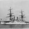
The Borodino was the lead ship of five Borodino class Battleships and the second finished. According to Wikipedia she was laid down on the 23rd May 1900, launched on the 8th September 1901and in service by August 1904. The Borodino was sunk during the Battle of Tsushima against the Japanese on the 27th May 1905.
Here is a link to wikipedia for those interested in finding out more about the ship. https://en.wikipedia.org/wiki/Russian_battleship_Borodino
There are 2 or 3 other Borodino class card models available that I am aware of. I previously mentioned that Russian ships are well catered as card models and I know of 12 other Russian ships available which were involved in the Battle of Tsushima. A few of which I would like to do as future builds. There are some Japanese ships from the battle available also, the Mikasa being one of note.
Another decision maker is the size of the pre-dreadnaught ships which at approximately 600mm long are half the length of WWII battleships so build duration should be proportionately shorter. I also want to get 1 or 2 smaller ships under my belt before tackling the Fuso or similar sized battleship.
I ordered the ship kit, laser cut forms, photo-etch detail set and the metal gun barrel set from GPM in Poland (http://gpm.pl/en ) which took 3 1/2 weeks to arrive. This was longer than the usual 2 weeks. The packaging was to GPMs usual high standard being well protected. Price wise card models are relatively cheap compared to other mediums and worked out approximately;
Borodino kit book – A$24
Laser cut forms – A$20
Photo-etch detail set – A$24
Metal gun barrel set – A$14
But postage is crippling to Australia coming in around the A$90 mark.
Okay let’s get started.
This is my 1st experience with the publisher Dom Bumagi so will be interesting to compare them with others. The first major surprise was how the kit is presented. It came in a plastic sleeve and looked like a usual A3 kit book but on opening it the pages are all loose leaf with no binding. This isn’t a problem as I usually separate the binding/staples and cut the pages in half to the individual sheets anyway for convenience and ease of handling/finding parts etc.
The front cover is stiff card with the picture on the front and the reverse as usual details the history of the ship and as usual is in the publishers native language but easy enough to convert to English. Also on the reverse of the cover are diagrams for a lot of the ‘ironwork’ such as railings, ladders, stairs etc. The diagrams show the various shapes to scale and the thicknesses of wire required to form them.
There are 6 thin pages for the hull skeleton and structure formwork which get glued to thicker card but these won’t be needed due to getting the laser cut forms. There are 6 pages of parts and on close inspection appear to be very well printed on the expected quality and thickness of paper although did expect more parts sheets.
The assembly diagrams are on 4 double sided glossy pages and these are very nicely detailed being computer renders as opposed to line drawings some publishers use.
Also in the sleeve is a thin strip with more parts on which I think must be an update to replace incorrect parts or additional details. There was also a small thin plastic cloth material with the various flags printed on to it. This is quite translucent and the flag colours are strong on one side but a bit light on the reverse.
There are 6 thick A3 sheets of laser cut form parts to replace the kit internal structures, skeleton, ribs etc and 1 thinner sheet for the ships boats, trestles etc. Having used laser cut forms in the past; these are a god send for quickly and accurately building the underlying structures. Previous experience of laser cut forms have been very good, going together perfectly so will see how these compare.
Card model ships aren’t as well catered for with regards to additional detail sets like the smaller 1:350 scale plastic kits but typically offer at least a set of laser cut card and/or a photo-etch set. I got the photo-etch detail set as although the same price as the kit book they do sharpen up the model replacing some parts which would otherwise be quite bulky in paper. The set also includes the nice eagle crest for the bow and the stern balcony.
There are little numbers next to each part which correspond to the equivalent paper part they replace.
The metal gun barrels are a bit of a backup as I intend to at least try to do the larger guns in card as supplied but can fall back to these if that doesn’t work out as planned. The set contains;
4x 305mm (~12”) in aluminium
12x 152mm (~6”) in brass
20x 75mm (~3”) in brass
20x 47mm (~2”) in brass
Really looking forward to getting back into ship modelling with this one.
Cheers
Slog
-
 Captain Slog got a reaction from Dan Vadas in Borodino by Captain Slog - Dom Bumagi - 1:200 - CARD
Hi laarmada, thanks for dropping by and the comment and to everyone for the likes.
Okay it’s been a while but I finally have an R&R partially to myself to do some modelling. I still haven’t plucked up the courage to attach the upper hull skins I prepared earlier so will continue working through the assemblies in the plan order.
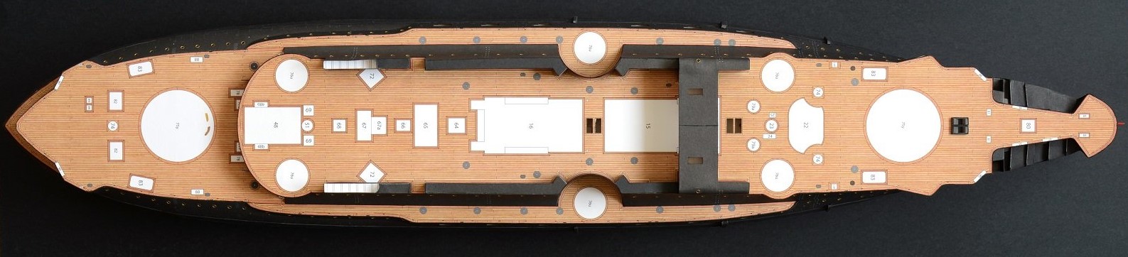
Assembly 20 is the conning tower deck which as the photo below shows has very little parts. The photo shows the top and underside of the deck and surprisingly (I double checked) there is no form to be sandwich between the 2 skins. The long strip is a skirting strip which goes around the perimeter but more on this later. There are 2 coamings (part 20c) to go round the openings for the stair wells (W) but not shown as I couldn’t find them! I am sure to stumble across them later but not needed to progress at this stage.
To join the top and underside skins together I cut the straight sections first on both parts; noting that the underside skin is shorter as the top skin sits on top of the deck bridge structure and the underside butts against it.
With the straight cuts made I had a reference for clamping the 2 parts together in alignment with clothes pegs. Then gently pulling them apart at one end I applied glue with a brush and then pressed the parts together, rolling the knife handle over them. Once left for a bit the process was repeated several times working to the other end and once finished was placed down on a sheet of glass and weighted down and left to dry. The curved sections were then cut out.
The plans were vague on the placement of the skirting strip. The plans show the underside of similar decks and shows the strip is flush with the top surface and extends down so this is what I did for this deck. The strip also had 2 bend marks which I can only guess the ends bend back on themselves to double thickness for the rear curve. I decided to chop them to length to single thickness for the complete perimeter. Note the rear section of the deck doesn’t have the skirt as this sits on the bridging structure.
Assembly 21 is a box type structure with some beams fixed underneath which I presume are for items to be laid across. The underside skin has the lines printed for the beam placement as does the laser cut form. The side skin only goes on 3 sides of the structure since the back side butts against the bridging structure.
All the parts cut out and formed up ready for assembly. With regards to the box structure since only a top and bottom form were provide I measured the height of the skin and used various offcuts of card to achieve the required height so the skin sits flush top and bottom. This was done to ease trying to align the top and bottom forms on the skin edges separately.
The beams were scored down the middle and folded against themselves for double paper thickness before cutting out.
Part 22 sits between the main deck and the conning tower deck shown above. There are no openings, doors or windows and I believe it is to support the mass of the conning tower above. Not a great deal of parts; 5 pieces of laser cut card to make up the underlying form and 2 skins. The braces (parts 26) will be discussed later.
Only point of note is to be mindful of the skin orientation. The white horizontal line is slightly off centre and I determined that the line should be closer to the bottom of the structure due to slight curve to take into account the main deck curvature.
The laser cut forms glued up and as usual a perfect fit. I keep saying and will say again the extra cost of the laser cut forms are worth it for ease and accuracy of fitment. The skinning is only as precise and accurate as the underlying form and I believe these have helped my skinning measurably.
The finished structure. I attached the front skin first (the one with the 2 concave cut outs). I firstly scored the back side of the sharp bends and preformed the concave curves with the knife handle. Then placing the form upside down on a glass sheet the skin was glued along the flat top and bottom edges and the centre support before offering up to the form and pressing home with a flat ruler.
Then each of the concave sections were glued and pressed home with the knife handle. The rear skin was done in a similar manner but only had the 2 convex curves preformed.
Returning back to the support brackets the photo shows the paper parts, according to the legend are folded down the middle. This is as per supplied by the kit. The laser cut forms are additions and are from thinner card to the rest of the underlying structures used so far.
This gives me 3 options for making the support brackets. I can either use the paper parts by themselves. Glue the skins on to the forms or the quickest and easiest option of just using the laser cut forms by themselves. This was what I did and just painted them with the black watercolours shown in a previous post.
The finished deck with the 2 structures glued on to the underside. The deck developed a bit of a bow between the 2 structures but won’t interfere with final glue up.
And shown in its place on the deck. This isn’t glued down yet, hence glimpses of white round the base of the front structure and I will need to tweek the rear structure to allow the whole deck to slide back fractionally. The beams can just be seen on the underside. There are still 5 items to be made and fitted in the space between the 2 structures but once the secondary gun turrets are in place little of this area will be seen.
That’s it for a couple of weeks. Really thinking about the hull skins being next!
Cheers
Slog
-
 Captain Slog got a reaction from DORIS in Borodino by Captain Slog - Dom Bumagi - 1:200 - CARD
Hi laarmada, thanks for dropping by and the comment and to everyone for the likes.
Okay it’s been a while but I finally have an R&R partially to myself to do some modelling. I still haven’t plucked up the courage to attach the upper hull skins I prepared earlier so will continue working through the assemblies in the plan order.
Assembly 20 is the conning tower deck which as the photo below shows has very little parts. The photo shows the top and underside of the deck and surprisingly (I double checked) there is no form to be sandwich between the 2 skins. The long strip is a skirting strip which goes around the perimeter but more on this later. There are 2 coamings (part 20c) to go round the openings for the stair wells (W) but not shown as I couldn’t find them! I am sure to stumble across them later but not needed to progress at this stage.
To join the top and underside skins together I cut the straight sections first on both parts; noting that the underside skin is shorter as the top skin sits on top of the deck bridge structure and the underside butts against it.
With the straight cuts made I had a reference for clamping the 2 parts together in alignment with clothes pegs. Then gently pulling them apart at one end I applied glue with a brush and then pressed the parts together, rolling the knife handle over them. Once left for a bit the process was repeated several times working to the other end and once finished was placed down on a sheet of glass and weighted down and left to dry. The curved sections were then cut out.
The plans were vague on the placement of the skirting strip. The plans show the underside of similar decks and shows the strip is flush with the top surface and extends down so this is what I did for this deck. The strip also had 2 bend marks which I can only guess the ends bend back on themselves to double thickness for the rear curve. I decided to chop them to length to single thickness for the complete perimeter. Note the rear section of the deck doesn’t have the skirt as this sits on the bridging structure.
Assembly 21 is a box type structure with some beams fixed underneath which I presume are for items to be laid across. The underside skin has the lines printed for the beam placement as does the laser cut form. The side skin only goes on 3 sides of the structure since the back side butts against the bridging structure.
All the parts cut out and formed up ready for assembly. With regards to the box structure since only a top and bottom form were provide I measured the height of the skin and used various offcuts of card to achieve the required height so the skin sits flush top and bottom. This was done to ease trying to align the top and bottom forms on the skin edges separately.
The beams were scored down the middle and folded against themselves for double paper thickness before cutting out.
Part 22 sits between the main deck and the conning tower deck shown above. There are no openings, doors or windows and I believe it is to support the mass of the conning tower above. Not a great deal of parts; 5 pieces of laser cut card to make up the underlying form and 2 skins. The braces (parts 26) will be discussed later.
Only point of note is to be mindful of the skin orientation. The white horizontal line is slightly off centre and I determined that the line should be closer to the bottom of the structure due to slight curve to take into account the main deck curvature.
The laser cut forms glued up and as usual a perfect fit. I keep saying and will say again the extra cost of the laser cut forms are worth it for ease and accuracy of fitment. The skinning is only as precise and accurate as the underlying form and I believe these have helped my skinning measurably.
The finished structure. I attached the front skin first (the one with the 2 concave cut outs). I firstly scored the back side of the sharp bends and preformed the concave curves with the knife handle. Then placing the form upside down on a glass sheet the skin was glued along the flat top and bottom edges and the centre support before offering up to the form and pressing home with a flat ruler.
Then each of the concave sections were glued and pressed home with the knife handle. The rear skin was done in a similar manner but only had the 2 convex curves preformed.
Returning back to the support brackets the photo shows the paper parts, according to the legend are folded down the middle. This is as per supplied by the kit. The laser cut forms are additions and are from thinner card to the rest of the underlying structures used so far.
This gives me 3 options for making the support brackets. I can either use the paper parts by themselves. Glue the skins on to the forms or the quickest and easiest option of just using the laser cut forms by themselves. This was what I did and just painted them with the black watercolours shown in a previous post.
The finished deck with the 2 structures glued on to the underside. The deck developed a bit of a bow between the 2 structures but won’t interfere with final glue up.
And shown in its place on the deck. This isn’t glued down yet, hence glimpses of white round the base of the front structure and I will need to tweek the rear structure to allow the whole deck to slide back fractionally. The beams can just be seen on the underside. There are still 5 items to be made and fitted in the space between the 2 structures but once the secondary gun turrets are in place little of this area will be seen.
That’s it for a couple of weeks. Really thinking about the hull skins being next!
Cheers
Slog
-
 Captain Slog got a reaction from coxswain in Borodino by Captain Slog - Dom Bumagi - 1:200 - CARD
Hi laarmada, thanks for dropping by and the comment and to everyone for the likes.
Okay it’s been a while but I finally have an R&R partially to myself to do some modelling. I still haven’t plucked up the courage to attach the upper hull skins I prepared earlier so will continue working through the assemblies in the plan order.
Assembly 20 is the conning tower deck which as the photo below shows has very little parts. The photo shows the top and underside of the deck and surprisingly (I double checked) there is no form to be sandwich between the 2 skins. The long strip is a skirting strip which goes around the perimeter but more on this later. There are 2 coamings (part 20c) to go round the openings for the stair wells (W) but not shown as I couldn’t find them! I am sure to stumble across them later but not needed to progress at this stage.
To join the top and underside skins together I cut the straight sections first on both parts; noting that the underside skin is shorter as the top skin sits on top of the deck bridge structure and the underside butts against it.
With the straight cuts made I had a reference for clamping the 2 parts together in alignment with clothes pegs. Then gently pulling them apart at one end I applied glue with a brush and then pressed the parts together, rolling the knife handle over them. Once left for a bit the process was repeated several times working to the other end and once finished was placed down on a sheet of glass and weighted down and left to dry. The curved sections were then cut out.
The plans were vague on the placement of the skirting strip. The plans show the underside of similar decks and shows the strip is flush with the top surface and extends down so this is what I did for this deck. The strip also had 2 bend marks which I can only guess the ends bend back on themselves to double thickness for the rear curve. I decided to chop them to length to single thickness for the complete perimeter. Note the rear section of the deck doesn’t have the skirt as this sits on the bridging structure.
Assembly 21 is a box type structure with some beams fixed underneath which I presume are for items to be laid across. The underside skin has the lines printed for the beam placement as does the laser cut form. The side skin only goes on 3 sides of the structure since the back side butts against the bridging structure.
All the parts cut out and formed up ready for assembly. With regards to the box structure since only a top and bottom form were provide I measured the height of the skin and used various offcuts of card to achieve the required height so the skin sits flush top and bottom. This was done to ease trying to align the top and bottom forms on the skin edges separately.
The beams were scored down the middle and folded against themselves for double paper thickness before cutting out.
Part 22 sits between the main deck and the conning tower deck shown above. There are no openings, doors or windows and I believe it is to support the mass of the conning tower above. Not a great deal of parts; 5 pieces of laser cut card to make up the underlying form and 2 skins. The braces (parts 26) will be discussed later.
Only point of note is to be mindful of the skin orientation. The white horizontal line is slightly off centre and I determined that the line should be closer to the bottom of the structure due to slight curve to take into account the main deck curvature.
The laser cut forms glued up and as usual a perfect fit. I keep saying and will say again the extra cost of the laser cut forms are worth it for ease and accuracy of fitment. The skinning is only as precise and accurate as the underlying form and I believe these have helped my skinning measurably.
The finished structure. I attached the front skin first (the one with the 2 concave cut outs). I firstly scored the back side of the sharp bends and preformed the concave curves with the knife handle. Then placing the form upside down on a glass sheet the skin was glued along the flat top and bottom edges and the centre support before offering up to the form and pressing home with a flat ruler.
Then each of the concave sections were glued and pressed home with the knife handle. The rear skin was done in a similar manner but only had the 2 convex curves preformed.
Returning back to the support brackets the photo shows the paper parts, according to the legend are folded down the middle. This is as per supplied by the kit. The laser cut forms are additions and are from thinner card to the rest of the underlying structures used so far.
This gives me 3 options for making the support brackets. I can either use the paper parts by themselves. Glue the skins on to the forms or the quickest and easiest option of just using the laser cut forms by themselves. This was what I did and just painted them with the black watercolours shown in a previous post.
The finished deck with the 2 structures glued on to the underside. The deck developed a bit of a bow between the 2 structures but won’t interfere with final glue up.
And shown in its place on the deck. This isn’t glued down yet, hence glimpses of white round the base of the front structure and I will need to tweek the rear structure to allow the whole deck to slide back fractionally. The beams can just be seen on the underside. There are still 5 items to be made and fitted in the space between the 2 structures but once the secondary gun turrets are in place little of this area will be seen.
That’s it for a couple of weeks. Really thinking about the hull skins being next!
Cheers
Slog
-
 Captain Slog got a reaction from nancysqueaks in Borodino by Captain Slog - Dom Bumagi - 1:200 - CARD
Hi laarmada, thanks for dropping by and the comment and to everyone for the likes.
Okay it’s been a while but I finally have an R&R partially to myself to do some modelling. I still haven’t plucked up the courage to attach the upper hull skins I prepared earlier so will continue working through the assemblies in the plan order.
Assembly 20 is the conning tower deck which as the photo below shows has very little parts. The photo shows the top and underside of the deck and surprisingly (I double checked) there is no form to be sandwich between the 2 skins. The long strip is a skirting strip which goes around the perimeter but more on this later. There are 2 coamings (part 20c) to go round the openings for the stair wells (W) but not shown as I couldn’t find them! I am sure to stumble across them later but not needed to progress at this stage.
To join the top and underside skins together I cut the straight sections first on both parts; noting that the underside skin is shorter as the top skin sits on top of the deck bridge structure and the underside butts against it.
With the straight cuts made I had a reference for clamping the 2 parts together in alignment with clothes pegs. Then gently pulling them apart at one end I applied glue with a brush and then pressed the parts together, rolling the knife handle over them. Once left for a bit the process was repeated several times working to the other end and once finished was placed down on a sheet of glass and weighted down and left to dry. The curved sections were then cut out.
The plans were vague on the placement of the skirting strip. The plans show the underside of similar decks and shows the strip is flush with the top surface and extends down so this is what I did for this deck. The strip also had 2 bend marks which I can only guess the ends bend back on themselves to double thickness for the rear curve. I decided to chop them to length to single thickness for the complete perimeter. Note the rear section of the deck doesn’t have the skirt as this sits on the bridging structure.
Assembly 21 is a box type structure with some beams fixed underneath which I presume are for items to be laid across. The underside skin has the lines printed for the beam placement as does the laser cut form. The side skin only goes on 3 sides of the structure since the back side butts against the bridging structure.
All the parts cut out and formed up ready for assembly. With regards to the box structure since only a top and bottom form were provide I measured the height of the skin and used various offcuts of card to achieve the required height so the skin sits flush top and bottom. This was done to ease trying to align the top and bottom forms on the skin edges separately.
The beams were scored down the middle and folded against themselves for double paper thickness before cutting out.
Part 22 sits between the main deck and the conning tower deck shown above. There are no openings, doors or windows and I believe it is to support the mass of the conning tower above. Not a great deal of parts; 5 pieces of laser cut card to make up the underlying form and 2 skins. The braces (parts 26) will be discussed later.
Only point of note is to be mindful of the skin orientation. The white horizontal line is slightly off centre and I determined that the line should be closer to the bottom of the structure due to slight curve to take into account the main deck curvature.
The laser cut forms glued up and as usual a perfect fit. I keep saying and will say again the extra cost of the laser cut forms are worth it for ease and accuracy of fitment. The skinning is only as precise and accurate as the underlying form and I believe these have helped my skinning measurably.
The finished structure. I attached the front skin first (the one with the 2 concave cut outs). I firstly scored the back side of the sharp bends and preformed the concave curves with the knife handle. Then placing the form upside down on a glass sheet the skin was glued along the flat top and bottom edges and the centre support before offering up to the form and pressing home with a flat ruler.
Then each of the concave sections were glued and pressed home with the knife handle. The rear skin was done in a similar manner but only had the 2 convex curves preformed.
Returning back to the support brackets the photo shows the paper parts, according to the legend are folded down the middle. This is as per supplied by the kit. The laser cut forms are additions and are from thinner card to the rest of the underlying structures used so far.
This gives me 3 options for making the support brackets. I can either use the paper parts by themselves. Glue the skins on to the forms or the quickest and easiest option of just using the laser cut forms by themselves. This was what I did and just painted them with the black watercolours shown in a previous post.
The finished deck with the 2 structures glued on to the underside. The deck developed a bit of a bow between the 2 structures but won’t interfere with final glue up.
And shown in its place on the deck. This isn’t glued down yet, hence glimpses of white round the base of the front structure and I will need to tweek the rear structure to allow the whole deck to slide back fractionally. The beams can just be seen on the underside. There are still 5 items to be made and fitted in the space between the 2 structures but once the secondary gun turrets are in place little of this area will be seen.
That’s it for a couple of weeks. Really thinking about the hull skins being next!
Cheers
Slog
-
Captain Slog reacted to RGL in IJN Yamato by RGL - FINISHED - Tamiya - 1/350 - PLASTIC
Ok, now I've painted all the squares,
i filled in all the spaces with red, then oversprayed the hull with more red. That's the thing with red, it's soo translucent,
Then I highlighted all the panels with a lighter red, toning down the back preshading. It actually looks a lot better in real life as the iphone camera does notcut it.. I intend to do a filter over the top then some very light dry brushing to really highlight the panels.
I did not do the ribbed version as I previously explained it does not make sense.
Then I can move upwards to do the upper hull after I leave it for a week to dry to I can mask it safely.
Then the weathering....
-
Captain Slog reacted to cog in IJN Musashi by cog - Tamiya - 1:350 - PLASTIC - old tool
Thanks Greg, but I feel the novice once again. It has been over 40 years since I build a ship of plastic, and in this size ... it is my first.
As promised, some better pictures, at least light-wise, still need to improve the depth of focus.
-
Captain Slog reacted to cog in IJN Musashi by cog - Tamiya - 1:350 - PLASTIC - old tool
New and improved formula I got my studio tripod out, increased iso to 800, set f-stop at 20, et voilà
if you look good, you see the front is perforated
or slightly easier on the eyes ...
-
 Captain Slog got a reaction from tadheus in Borodino by Captain Slog - Dom Bumagi - 1:200 - CARD
Hi laarmada, thanks for dropping by and the comment and to everyone for the likes.
Okay it’s been a while but I finally have an R&R partially to myself to do some modelling. I still haven’t plucked up the courage to attach the upper hull skins I prepared earlier so will continue working through the assemblies in the plan order.
Assembly 20 is the conning tower deck which as the photo below shows has very little parts. The photo shows the top and underside of the deck and surprisingly (I double checked) there is no form to be sandwich between the 2 skins. The long strip is a skirting strip which goes around the perimeter but more on this later. There are 2 coamings (part 20c) to go round the openings for the stair wells (W) but not shown as I couldn’t find them! I am sure to stumble across them later but not needed to progress at this stage.
To join the top and underside skins together I cut the straight sections first on both parts; noting that the underside skin is shorter as the top skin sits on top of the deck bridge structure and the underside butts against it.
With the straight cuts made I had a reference for clamping the 2 parts together in alignment with clothes pegs. Then gently pulling them apart at one end I applied glue with a brush and then pressed the parts together, rolling the knife handle over them. Once left for a bit the process was repeated several times working to the other end and once finished was placed down on a sheet of glass and weighted down and left to dry. The curved sections were then cut out.
The plans were vague on the placement of the skirting strip. The plans show the underside of similar decks and shows the strip is flush with the top surface and extends down so this is what I did for this deck. The strip also had 2 bend marks which I can only guess the ends bend back on themselves to double thickness for the rear curve. I decided to chop them to length to single thickness for the complete perimeter. Note the rear section of the deck doesn’t have the skirt as this sits on the bridging structure.
Assembly 21 is a box type structure with some beams fixed underneath which I presume are for items to be laid across. The underside skin has the lines printed for the beam placement as does the laser cut form. The side skin only goes on 3 sides of the structure since the back side butts against the bridging structure.
All the parts cut out and formed up ready for assembly. With regards to the box structure since only a top and bottom form were provide I measured the height of the skin and used various offcuts of card to achieve the required height so the skin sits flush top and bottom. This was done to ease trying to align the top and bottom forms on the skin edges separately.
The beams were scored down the middle and folded against themselves for double paper thickness before cutting out.
Part 22 sits between the main deck and the conning tower deck shown above. There are no openings, doors or windows and I believe it is to support the mass of the conning tower above. Not a great deal of parts; 5 pieces of laser cut card to make up the underlying form and 2 skins. The braces (parts 26) will be discussed later.
Only point of note is to be mindful of the skin orientation. The white horizontal line is slightly off centre and I determined that the line should be closer to the bottom of the structure due to slight curve to take into account the main deck curvature.
The laser cut forms glued up and as usual a perfect fit. I keep saying and will say again the extra cost of the laser cut forms are worth it for ease and accuracy of fitment. The skinning is only as precise and accurate as the underlying form and I believe these have helped my skinning measurably.
The finished structure. I attached the front skin first (the one with the 2 concave cut outs). I firstly scored the back side of the sharp bends and preformed the concave curves with the knife handle. Then placing the form upside down on a glass sheet the skin was glued along the flat top and bottom edges and the centre support before offering up to the form and pressing home with a flat ruler.
Then each of the concave sections were glued and pressed home with the knife handle. The rear skin was done in a similar manner but only had the 2 convex curves preformed.
Returning back to the support brackets the photo shows the paper parts, according to the legend are folded down the middle. This is as per supplied by the kit. The laser cut forms are additions and are from thinner card to the rest of the underlying structures used so far.
This gives me 3 options for making the support brackets. I can either use the paper parts by themselves. Glue the skins on to the forms or the quickest and easiest option of just using the laser cut forms by themselves. This was what I did and just painted them with the black watercolours shown in a previous post.
The finished deck with the 2 structures glued on to the underside. The deck developed a bit of a bow between the 2 structures but won’t interfere with final glue up.
And shown in its place on the deck. This isn’t glued down yet, hence glimpses of white round the base of the front structure and I will need to tweek the rear structure to allow the whole deck to slide back fractionally. The beams can just be seen on the underside. There are still 5 items to be made and fitted in the space between the 2 structures but once the secondary gun turrets are in place little of this area will be seen.
That’s it for a couple of weeks. Really thinking about the hull skins being next!
Cheers
Slog
-
 Captain Slog got a reaction from popeye the sailor in IJN Yamato by Wblakeny - DeAgostini - 1/250
I look forward to following your build also.
Greg, I believe Trumpeter are planning on releasing a 1:200 scale Yamato.
Cheers
Slog
-
Captain Slog reacted to gjdale in 1949 Chris-Craft 19' Racing Runabout by gjdale - FINISHED -Dumas - 1:8 Scale - RADIO
Thanks Slog, Mobbsie and Popeye, and also to all the "likes".
Only a minor update today - have been distracted with other activities lately, and the last couple of days have been over 40 degrees C, so not a lot of energy for anything! But we have made some progress nevertheless.
Chrome Plating - First Adventures
To complete both the Wheel assembly and the Cutwater, some chrome plating was called for. Following the lead of others over on the RC Groups forum, I acquired a Caswell Chrome Plating Kit. It was relatively inexpensive and, as it turned out, quite easy to use. The kit consists of a small transformer with two leads extending from it. The black lead has an alligator clip attached and this gets attached to the part being plated. The red lead plugs into a small wand that has its end wrapped in a bandage, and this is soaked in the plating solution and then rubbed onto the part. And then the magic happens. It’s as easy as that. Not much to show, as I didn’t take photos of the process. Here is the end result though (the camera is not kind – it looks a whole lot better at “normal” viewing distance). Mmmmmmm……shiny…….
-
Captain Slog reacted to WBlakeny in IJN Yamato by Wblakeny - DeAgostini - 1/250
To fix the bulkheads, i first made a cart template using the side which was not damaged. Afterwards i glued the template on the bulkhead.
I then filled the voids at the corners with some wood filler. Once dry, i sanded the corners smooth.
I remade the part that was to much damaged, using some old plywood i had lying around.
-
 Captain Slog got a reaction from mtaylor in IJN Yamato by Wblakeny - DeAgostini - 1/250
I look forward to following your build also.
Greg, I believe Trumpeter are planning on releasing a 1:200 scale Yamato.
Cheers
Slog
-
Captain Slog reacted to cog in IJN Musashi by cog - Tamiya - 1:350 - PLASTIC - old tool
Actually manage to do something today. Not much folding but a little bit of this, and a little bit of that ...
Neither the tower, nor the funnel are glued yet
I'll try to get some better pictures with daylight tomorrow
-
Captain Slog reacted to shipaholic in HMB Endeavour by shipaholic - FINISHED - Eaglemoss - 1/51
Its 37 degrees Celsius here today and my ship in the garage is suffering the sags, the mainstay especially and the shrouds are loose. I brought it inside and placed it on the bookcase in my study (my indoor mancave) where my Victory normally sits. Looks okay there, my Vic might be looking for a new home when I finish the Endeavour.
-
 Captain Slog got a reaction from Canute in IJN Yamato by Wblakeny - DeAgostini - 1/250
I look forward to following your build also.
Greg, I believe Trumpeter are planning on releasing a 1:200 scale Yamato.
Cheers
Slog
-
 Captain Slog got a reaction from WackoWolf in IJN Yamato by Wblakeny - DeAgostini - 1/250
I look forward to following your build also.
Greg, I believe Trumpeter are planning on releasing a 1:200 scale Yamato.
Cheers
Slog
-
Captain Slog reacted to WBlakeny in IJN Yamato by Wblakeny - DeAgostini - 1/250
To fix the warped hull, i decided to rebuild the hull. I carefully took apart the components.
Luckily it proved to go rather well, i think the former builder didn't use wood glue but a simple contact glue.
Once the parts got separated, the degree of warping became very obvious.