
HOLIDAY DONATION DRIVE - SUPPORT MSW - DO YOUR PART TO KEEP THIS GREAT FORUM GOING! (Only 13 donations so far - C'mon guys!)
×
Keith Black
-
Posts
6,558 -
Joined
-
Last visited
Content Type
Profiles
Forums
Gallery
Events
Everything posted by Keith Black
-
John, welcome to MSW. Please share your Cutty Sark rigging efforts in a build log.
-
 Chris, she looks lovely. It isn't a show boat, it a working craft besides fish don't capisce boat hulls perfect or no.
 -
"Sand Pebbles" motor Sampan from 1966 movie
Keith Black replied to JRB's topic in Nautical/Naval History
John, welcome to MSW. I would love to attempt to make a model of the San Pablo but alas, there's not enough sand left in the glass. I wish you well in your search for plans. If you're successful I hope you'll start a build log. -
Siggi, that is absolutely beautiful. The painter's definitely need a raise and an extra ration of grog!
-
Upgrade kit for 1/200 scale Mikasa pre-dreadnought model
Keith Black replied to Cal123's topic in Plastic model kits
Cal, my apologies. Had I know about the poor business practices of Freetime Hobbies I obviously would never have provided the link. I'm very glad you were able to source your upgrade kit elsewhere. Hopefully one of the NRG staff will see this and add Freetime Hobbies to the bad source list. -
Nicely done.
-
Brian, my deepest sympathies to your wife, her family, and to you. The Cairo is looking top notch in every way, you're doing an amazing job modeling her.
-
Bob, welcome to MSW. I hope your cataract surgery goes well, being able to see well is the greatest asset in modeling.
-
Iraymo, it matters not that you're a woman, what matters is that you have the desire to learn the hobby. It makes it that much more special that you are a woman in that we need more women involved in the hobby. Here at MSW/NGR there are no ceilings or boundaries, you can fly as high and far as YOU want to. I'm looking forward to your Pram build and hopefully more to follow. Doris, one of our female members is absolutely amazing, here is the link to her build of the Royal Katherine.
- 85 replies
-
- 4
-

-

-
- Lowell Grand Banks Dory
- First Build
- (and 2 more)
-
Sorry, Rob. If I only knew how to read ...... "So starting on the bowsprit gonna see how this goes because I never made this big of a hole in the hull before" You have to drill the hole for the bowsprit. Start with a tiny hole and work your way up to the finished hole size.
-
Painted Military Figures by Roger Pellett
Keith Black replied to Roger Pellett's topic in Completed non-ship models
Roger, they look great. Do you apply a protective coating after painting? -
Rob, the mast holes are already drilled aren't they? Making the mast is a fun task, I hope you enjoy it.
-
Iraymo, congratulation! I am so very proud for you, a wonderful job on your first build. I hope you have a prominent place to display her, she deserves it.
- 85 replies
-
- 3
-
-
-
- Lowell Grand Banks Dory
- First Build
- (and 2 more)
-
Hello from sunny Southern California
Keith Black replied to boatsNbeers's topic in New member Introductions
Dan, welcome to MSW/NGR. I look forward to seeing your first build log. -
Do not use the close your eyes mix em up and pick one method.
-
Trond, the deck looks great. Color is a personal choice but I like the natural finish you have on the right. Because of the tarred standing rigging and the tar being transferred to the decks on the soles of the sailors shoes, ship captains would periodically have the decks "holy stoned" with seawater. That plus the bleaching of the sun would make one think that decks were a worn natural color.
-
Amati Rainbow JClass by Markus16
Keith Black replied to Markus16's topic in New member Introductions
Markus, welcome to MSW. Looking forward to your J Class build log. -
Marc, welcome to MSW. I look forward to seeing your build log.
-
Please post a picture of the rope next to the hole, I'd like to see the two sizes side by side. We'll get this figured out.
- 85 replies
-
- 2
-
-
- Lowell Grand Banks Dory
- First Build
- (and 2 more)
-
Iraymo, you could try drilling out the holes to a larger size. You would want to test drill on a piece of scrap first to see if the "rope" will pass through. You can also try gluing the rope to a piece of wire or whatever that will pass through the hole taking the rope with it.
- 85 replies
-
- 2
-
-
- Lowell Grand Banks Dory
- First Build
- (and 2 more)
-
Nehemiah, welcome to MSW. I look forward to seeing a build log from you in the near future.
-
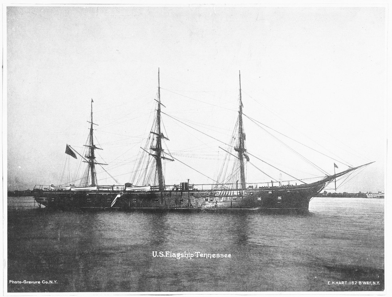
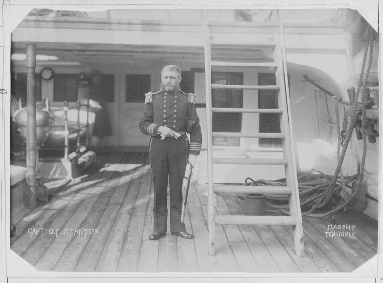
Trond, this is a Hatton and Hart photograph of the USS Tennessee ca 1880 showing close up deck detail. There is no visible evidence of nail, screw, or even plugs. Also notice the two patches behind Captain Stanton, there is also no evidence of nail, screw, or plugs.
-
Trond, the deck is looking very nice.
-
Retired for the first time !...
Keith Black replied to Lou_Papet's topic in New member Introductions
Jean Pierre, welcome to MSW. Glad to have you aboard.
