


JerseyCity Frankie
-
Posts
1,338 -
Joined
-
Last visited
Reputation Activity
-

 JerseyCity Frankie got a reaction from Piet in Charles W Morgan by texxn5 - FINISHED - Model Shipways - 1:64
It pained me greatly to say anything at all critical of your otherwise really impressive model. I had strong misgivings about saying anything! I know myself, I have a hard time accepting criticism, its a character flaw of mine.
-
JerseyCity Frankie reacted to texxn5 in Charles W Morgan by texxn5 - FINISHED - Model Shipways - 1:64
Hi Frankie, I really want to thank you for pointing this out to me. As I sat back and looked at it I rally could see how bad it looked. I hate to have to tear things apart, but I started trying. I was so caught up in what I was doing, I failed to look at it objectively. Your comment woke me up to my oblivion. It is a slow process but I'm tackling it now. Part of the problem is that I glued the string with Testor's Green cement and it is the devil to get loose. Plus the fact that the string I used is cotton, so it comes apart. Have no fear - Chuck is here to bail me out. I have some of his light brown .008 line that I had set aside for something else and it works perfectly - only problem is I don't have enough of it, so I have to get an order in to him asap. Thanks again, I'll post pictures shortly.
John
-
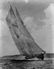
 JerseyCity Frankie got a reaction from Stockholm tar in Rigging a bowsprit heel rope on Cutter Sherbourne 1763
It certainly makes me wonder what the circumstances were that would prompt the decision to run the bowsprit inboard. If you can simply take in sail, why go to all the trouble of physically running the bowsprit inboard? Consider that "all that trouble ALSO could mean striking the topmast, since the topmast stay would lose effectiveness the closer inboard it was made.
I suppose if the boat was pitching excessively it would run the tip of the bowsprit into the sea and threaten its breaking off and this would necessitate getting it in out of the way?
It certainly must have been an exciting life being crew on one of these cutters, the fastest thing afloat but with no creature comforts. Very little room for anything on deck and when the time comes to strike the rig, imagine the chaos for the leiutenant giving orders in the proper sequence. There would be no room for any shortcomings in crew competence. With everything struck, wouldn't every available inch of deck space be piled high with coils and spars? Then when the weather moderates, put it all back in place!
-
JerseyCity Frankie got a reaction from Stockholm tar in Rigging a bowsprit heel rope on Cutter Sherbourne 1763
The spar would run inboard very easily in comparison to the effort required to run it out. The geometry of the standing rigging bearing on its outer end would always be trying to run it inboard. Also there are plenty of lines already attached to the spar convenient for hauling it inboard, and note that these lines need not be attached directly to the heel of the spar, a purchase at any point on the spar could be used for pulling the spar back inboard.
Also the fid holes clearly are for adjusting the sail area and center of effort of the vessel. Considering the fact that cutters already had Bowsprit Travelers its a wonder the designers felt this extra bit of control was worth all the trouble of configuring a spar so it could be adjusted this way.
-
 JerseyCity Frankie got a reaction from tkay11 in Rigging a bowsprit heel rope on Cutter Sherbourne 1763
The spar would run inboard very easily in comparison to the effort required to run it out. The geometry of the standing rigging bearing on its outer end would always be trying to run it inboard. Also there are plenty of lines already attached to the spar convenient for hauling it inboard, and note that these lines need not be attached directly to the heel of the spar, a purchase at any point on the spar could be used for pulling the spar back inboard.
Also the fid holes clearly are for adjusting the sail area and center of effort of the vessel. Considering the fact that cutters already had Bowsprit Travelers its a wonder the designers felt this extra bit of control was worth all the trouble of configuring a spar so it could be adjusted this way.
-
JerseyCity Frankie got a reaction from tkay11 in Rigging a bowsprit heel rope on Cutter Sherbourne 1763
It certainly makes me wonder what the circumstances were that would prompt the decision to run the bowsprit inboard. If you can simply take in sail, why go to all the trouble of physically running the bowsprit inboard? Consider that "all that trouble ALSO could mean striking the topmast, since the topmast stay would lose effectiveness the closer inboard it was made.
I suppose if the boat was pitching excessively it would run the tip of the bowsprit into the sea and threaten its breaking off and this would necessitate getting it in out of the way?
It certainly must have been an exciting life being crew on one of these cutters, the fastest thing afloat but with no creature comforts. Very little room for anything on deck and when the time comes to strike the rig, imagine the chaos for the leiutenant giving orders in the proper sequence. There would be no room for any shortcomings in crew competence. With everything struck, wouldn't every available inch of deck space be piled high with coils and spars? Then when the weather moderates, put it all back in place!
-
 JerseyCity Frankie got a reaction from Beef Wellington in Charles W Morgan by texxn5 - FINISHED - Model Shipways - 1:64
Oh dear I worry the lashings on those ratlines are made of too thick stuff.
-
 JerseyCity Frankie got a reaction from GLakie in Charles W Morgan by texxn5 - FINISHED - Model Shipways - 1:64
Oh dear I worry the lashings on those ratlines are made of too thick stuff.
-
JerseyCity Frankie reacted to EdT in Young America 1853 by EdT - FINISHED - extreme clipper
Young America - extreme clipper 1853
Part 110 – Cabin Deck
Anything to avoid metal sheathing. Actually, not much can proceed on the main deck until the framing of the poop and forecastle has at least begun, so this week I have been working on the cabin deck facilities. The poop beams cannot be installed until all of that work is finished. In the first picture the poop deck beams have been made, cut to length and pinned in place.
The cabin deck partitions have to be cut out around these beams so having them pinned in place is a prerequisite for the partition work.
The next picture shows the first steps on the partitions.
The breast beam has been glued in with pillars on either side of what will be the "grand entrance" to the cabin deck level. The central section of this beam will later be cut out so people don't have to crawl into the cabin deck. The beginning of the paneled partition shown is the forward bulkhead of the captain's day cabin with his bookcase cabinet pre-installed – but paneled doors not yet carved.
We do not know what all these facilities looked like on Young America, so this is all creative design on my part – but typical of the period and the class. Some of these ships were very elegant in décor, because the few passengers carried were probably quite wealthy. I am using black walnut to simulate old mahogany for all the paneling and furnishings. Otherwise it is all going to be fairly Spartan.
The first semi-indulgence in elegance is the double, curved entrance staircase from the main deck. The starting block is shown in the next picture.
The panels to the right are representative of the final paneling finish. The next picture shows the perimeter walls of the cabin areas at the sides.
The central "salon area" was open with tables and places to sit. Modeling of this will be limited to preserve the view into the lower regions.
In the next picture the bannister of the staircase is being sanded to size after the treads, the balusters and the lower part of the rail were fitted.
There will be a cap rail to cover the mortise holes for the balusters.
The next picture shows the paneling of the fore and aft partitions in progress.
The panels are built up using thin strips on an underlying thin sheet of walnut. The port panels are incomplete in this picture.
In the next picture the capping rail on the staircase has been fitted but not yet trimmed, the paneling of the starboard wall completed and door hardware installed.
The captain's cabin was traditionally on the starboard side, close to the exit to the main deck. In this arrangement his day cabin doorway is right outside the stairs. The last picture shows the inside of the captain's cabins from above.
The day cabin in the center of the photo has a table, built-in bench and the book cabinet. It is quite small. A doorway to the left leads to his sleeping quarters. Only his dresser is in place as yet. In addition to the captain's palatial space, there are six other cabins for passengers and the mate. All are quite small. There will also be two small cubicles aft – a toilet and a storage space.
The crew space on these ships was a large cabin on the main deck – to be constructed much later.
Metal sheathing has begun, but has been held up waiting for some .002" brass.
Ed
-
JerseyCity Frankie got a reaction from tkay11 in Rigging a bowsprit heel rope on Cutter Sherbourne 1763
Sounds to me like this arrangement is exactly like that of the Top Rope on a topmast. If you look at how topmasts are swayed up, its very easy to imagine this same principle being used horizontally for the bowsprit. I built a cutter once and at the time I was frustrated at the lack of documentation of how the bowsprit was run in and out, and exactly how the bits or samson post at the windlass forward was shaped in order to control the bowsprit. But there must be a fid of some sort to hold the spar in place once its located properly.
But that led to further unanswered questions concerning the Bowsprit. For instance, were there only two positions available, All the way inboard and all the way outboard, or was there a way to run the spar out only halfway? If this is so, there would have to be another fid hole somewhere along the inner third of the bowsprit? But I can't see the riggers allowing a hole in the spar anywhere along its length, particularly on a cutter. Alternatively there could PERHAPS have been a fitting on the fife rail to accept the fid at the spars heel?
-
JerseyCity Frankie reacted to greatgalleons in Jolie Brise 1913 by greatgalleons - FINISHED - Artesania Latina - Pilot Cutter
so for the sails I never use the cheese cloth the kits provide. I purchased some light weight off white material at hobby lobby
I use for all my builds. The Jolie Brise has a faded reddish set of sails so I used burgundy and brown food coloring with tea stain solution to stain the sails I sewed for this kit. I modified the length for the large spanker sail to fit to compensate for the addition of the coach roof. One little change in the kit will make a difference to other areas of interest.
-
JerseyCity Frankie reacted to greatgalleons in Jolie Brise 1913 by greatgalleons - FINISHED - Artesania Latina - Pilot Cutter
refine hull and paint
-
 JerseyCity Frankie got a reaction from druxey in Pin Rails
My two or three cents about pins and pinrails: Use the smallest possible pin you can find or make, this will prevent a cascading series of scale issues from developing later. Obviously the smaller the pins, the more can be fit on a rail. Every pinrail I have seen has the pins spaced evenly about 10" apart. Any closer together and the belayed lines passed around the pins would interfere with each other and the sailors couldn't get their hands in there.
Most of the pins I see on models are too big and have en exaggerated shape and if scaled up would look like three foot high wooden lightbulbs. Most actual pins are two inches wide at most and are seldom longer than 18". They do flare out on their upper halves, but only a bit and a human hand can still grasp them- the commercially available ones all too often flare out into nearly spherical globes. Also consider that once there is a line on the pin, the pin itself is no longer visible except maybe its very top. For this reason I mostly just use wire or rod.
An issue that always arises is the apparent low number of pins, modelers often find their accurate plans do not provide enough places for all the lines to belay to. This is a very common problem.
As mentioned above, another very common problem is not fixing your pinrail strongly enough. There isn't very much tension on them but the pinrails on models do very often pull out or distort from the accumulated strain placed on them by the rigging, which apparently over time can contract.
-
 JerseyCity Frankie got a reaction from joske in Making a ships bell from brass rod and wire
I needed a bell for a model I am restoring and I did not want to see what the internet had, nor wait for it to arrive if it even existed in the first place.
3mm was the thickest solid rod my local art supply store had, I was hoping for something thicker that I could then carve down to a bell shape.
Instead I used a ring of brass wire set into a grove cut into the rod stock to represent the flared out shape of the bottom of the bell.
I used the high speed cut off wheel for most of this. I have a love/hate relationship with these disks. On the one hand they cut through anything. On the other hand they are so fragile they always break apart. I have used hundreds of them and maybe only three of those actually wore down to a tiny doughnut. The rest broke being handled or flew apart while under load. I have never been cut by flying pieces but then again I ALWAYS use eye protection when using a cut off wheel.
I have no lathe so this is all by hand and eye. I cut a groove around the rod and I round off the end of the rod to resemble the curved top of the bell. I wrap thickish brass wire down into the groove I cut, aiming for exactly the right length so the wire forms a ring. Then I hammer this down with a tack hammer, trying to mash the wire into the groove while smoothing the juncture with the rod.
Then I use the cut off wheel some more, this time as a shaping tool, smoothing the transition from the wire to the rod.
Then I part off the "bell" and as I was doing this I realized I could leave a bit of the "stalk" intact to look like a clapper.
I drilled a hole in the top of the bell and put in a fine brass wire eye, secured with super glue. I did not want to solder anything as I was going to use the brass in its natural finish.
-
 JerseyCity Frankie got a reaction from Mfelinger in Making a ships bell from brass rod and wire
I needed a bell for a model I am restoring and I did not want to see what the internet had, nor wait for it to arrive if it even existed in the first place.
3mm was the thickest solid rod my local art supply store had, I was hoping for something thicker that I could then carve down to a bell shape.
Instead I used a ring of brass wire set into a grove cut into the rod stock to represent the flared out shape of the bottom of the bell.
I used the high speed cut off wheel for most of this. I have a love/hate relationship with these disks. On the one hand they cut through anything. On the other hand they are so fragile they always break apart. I have used hundreds of them and maybe only three of those actually wore down to a tiny doughnut. The rest broke being handled or flew apart while under load. I have never been cut by flying pieces but then again I ALWAYS use eye protection when using a cut off wheel.
I have no lathe so this is all by hand and eye. I cut a groove around the rod and I round off the end of the rod to resemble the curved top of the bell. I wrap thickish brass wire down into the groove I cut, aiming for exactly the right length so the wire forms a ring. Then I hammer this down with a tack hammer, trying to mash the wire into the groove while smoothing the juncture with the rod.
Then I use the cut off wheel some more, this time as a shaping tool, smoothing the transition from the wire to the rod.
Then I part off the "bell" and as I was doing this I realized I could leave a bit of the "stalk" intact to look like a clapper.
I drilled a hole in the top of the bell and put in a fine brass wire eye, secured with super glue. I did not want to solder anything as I was going to use the brass in its natural finish.
-
 JerseyCity Frankie got a reaction from Landlubber Mike in Making a ships bell from brass rod and wire
I needed a bell for a model I am restoring and I did not want to see what the internet had, nor wait for it to arrive if it even existed in the first place.
3mm was the thickest solid rod my local art supply store had, I was hoping for something thicker that I could then carve down to a bell shape.
Instead I used a ring of brass wire set into a grove cut into the rod stock to represent the flared out shape of the bottom of the bell.
I used the high speed cut off wheel for most of this. I have a love/hate relationship with these disks. On the one hand they cut through anything. On the other hand they are so fragile they always break apart. I have used hundreds of them and maybe only three of those actually wore down to a tiny doughnut. The rest broke being handled or flew apart while under load. I have never been cut by flying pieces but then again I ALWAYS use eye protection when using a cut off wheel.
I have no lathe so this is all by hand and eye. I cut a groove around the rod and I round off the end of the rod to resemble the curved top of the bell. I wrap thickish brass wire down into the groove I cut, aiming for exactly the right length so the wire forms a ring. Then I hammer this down with a tack hammer, trying to mash the wire into the groove while smoothing the juncture with the rod.
Then I use the cut off wheel some more, this time as a shaping tool, smoothing the transition from the wire to the rod.
Then I part off the "bell" and as I was doing this I realized I could leave a bit of the "stalk" intact to look like a clapper.
I drilled a hole in the top of the bell and put in a fine brass wire eye, secured with super glue. I did not want to solder anything as I was going to use the brass in its natural finish.
-
 JerseyCity Frankie got a reaction from usedtosail in Making a ships bell from brass rod and wire
I needed a bell for a model I am restoring and I did not want to see what the internet had, nor wait for it to arrive if it even existed in the first place.
3mm was the thickest solid rod my local art supply store had, I was hoping for something thicker that I could then carve down to a bell shape.
Instead I used a ring of brass wire set into a grove cut into the rod stock to represent the flared out shape of the bottom of the bell.
I used the high speed cut off wheel for most of this. I have a love/hate relationship with these disks. On the one hand they cut through anything. On the other hand they are so fragile they always break apart. I have used hundreds of them and maybe only three of those actually wore down to a tiny doughnut. The rest broke being handled or flew apart while under load. I have never been cut by flying pieces but then again I ALWAYS use eye protection when using a cut off wheel.
I have no lathe so this is all by hand and eye. I cut a groove around the rod and I round off the end of the rod to resemble the curved top of the bell. I wrap thickish brass wire down into the groove I cut, aiming for exactly the right length so the wire forms a ring. Then I hammer this down with a tack hammer, trying to mash the wire into the groove while smoothing the juncture with the rod.
Then I use the cut off wheel some more, this time as a shaping tool, smoothing the transition from the wire to the rod.
Then I part off the "bell" and as I was doing this I realized I could leave a bit of the "stalk" intact to look like a clapper.
I drilled a hole in the top of the bell and put in a fine brass wire eye, secured with super glue. I did not want to solder anything as I was going to use the brass in its natural finish.
-
 JerseyCity Frankie got a reaction from Canute in Making a ships bell from brass rod and wire
I needed a bell for a model I am restoring and I did not want to see what the internet had, nor wait for it to arrive if it even existed in the first place.
3mm was the thickest solid rod my local art supply store had, I was hoping for something thicker that I could then carve down to a bell shape.
Instead I used a ring of brass wire set into a grove cut into the rod stock to represent the flared out shape of the bottom of the bell.
I used the high speed cut off wheel for most of this. I have a love/hate relationship with these disks. On the one hand they cut through anything. On the other hand they are so fragile they always break apart. I have used hundreds of them and maybe only three of those actually wore down to a tiny doughnut. The rest broke being handled or flew apart while under load. I have never been cut by flying pieces but then again I ALWAYS use eye protection when using a cut off wheel.
I have no lathe so this is all by hand and eye. I cut a groove around the rod and I round off the end of the rod to resemble the curved top of the bell. I wrap thickish brass wire down into the groove I cut, aiming for exactly the right length so the wire forms a ring. Then I hammer this down with a tack hammer, trying to mash the wire into the groove while smoothing the juncture with the rod.
Then I use the cut off wheel some more, this time as a shaping tool, smoothing the transition from the wire to the rod.
Then I part off the "bell" and as I was doing this I realized I could leave a bit of the "stalk" intact to look like a clapper.
I drilled a hole in the top of the bell and put in a fine brass wire eye, secured with super glue. I did not want to solder anything as I was going to use the brass in its natural finish.
-
 JerseyCity Frankie got a reaction from shihawk in Making a ships bell from brass rod and wire
I needed a bell for a model I am restoring and I did not want to see what the internet had, nor wait for it to arrive if it even existed in the first place.
3mm was the thickest solid rod my local art supply store had, I was hoping for something thicker that I could then carve down to a bell shape.
Instead I used a ring of brass wire set into a grove cut into the rod stock to represent the flared out shape of the bottom of the bell.
I used the high speed cut off wheel for most of this. I have a love/hate relationship with these disks. On the one hand they cut through anything. On the other hand they are so fragile they always break apart. I have used hundreds of them and maybe only three of those actually wore down to a tiny doughnut. The rest broke being handled or flew apart while under load. I have never been cut by flying pieces but then again I ALWAYS use eye protection when using a cut off wheel.
I have no lathe so this is all by hand and eye. I cut a groove around the rod and I round off the end of the rod to resemble the curved top of the bell. I wrap thickish brass wire down into the groove I cut, aiming for exactly the right length so the wire forms a ring. Then I hammer this down with a tack hammer, trying to mash the wire into the groove while smoothing the juncture with the rod.
Then I use the cut off wheel some more, this time as a shaping tool, smoothing the transition from the wire to the rod.
Then I part off the "bell" and as I was doing this I realized I could leave a bit of the "stalk" intact to look like a clapper.
I drilled a hole in the top of the bell and put in a fine brass wire eye, secured with super glue. I did not want to solder anything as I was going to use the brass in its natural finish.
-
JerseyCity Frankie reacted to michael mott in Making a ships bell from brass rod and wire
A neat solution indeed.
Michael
-
JerseyCity Frankie got a reaction from tkay11 in Making a ships bell from brass rod and wire
I needed a bell for a model I am restoring and I did not want to see what the internet had, nor wait for it to arrive if it even existed in the first place.
3mm was the thickest solid rod my local art supply store had, I was hoping for something thicker that I could then carve down to a bell shape.
Instead I used a ring of brass wire set into a grove cut into the rod stock to represent the flared out shape of the bottom of the bell.
I used the high speed cut off wheel for most of this. I have a love/hate relationship with these disks. On the one hand they cut through anything. On the other hand they are so fragile they always break apart. I have used hundreds of them and maybe only three of those actually wore down to a tiny doughnut. The rest broke being handled or flew apart while under load. I have never been cut by flying pieces but then again I ALWAYS use eye protection when using a cut off wheel.
I have no lathe so this is all by hand and eye. I cut a groove around the rod and I round off the end of the rod to resemble the curved top of the bell. I wrap thickish brass wire down into the groove I cut, aiming for exactly the right length so the wire forms a ring. Then I hammer this down with a tack hammer, trying to mash the wire into the groove while smoothing the juncture with the rod.
Then I use the cut off wheel some more, this time as a shaping tool, smoothing the transition from the wire to the rod.
Then I part off the "bell" and as I was doing this I realized I could leave a bit of the "stalk" intact to look like a clapper.
I drilled a hole in the top of the bell and put in a fine brass wire eye, secured with super glue. I did not want to solder anything as I was going to use the brass in its natural finish.
-
 JerseyCity Frankie got a reaction from allanyed in 200 sketches of Traditional Pacific Islanders rigs
Found this link on Reddit, looks like13 pages from a sketchbook have been reproduced. http://www.cherini.eu/etnografia/IND/index.html
the root website doesn't translate to English but if you click on the hotlinks there is treasure: http://www.cherini.eu/and I do mean TREASURE, I have not seen so much information on delightful non-Western rigs before.
-
JerseyCity Frankie reacted to SuperSylvester in Dutch Two-decker by SuperSylvester - 1/50 scale - from plans of Heinrich Winter's Hohenzollern model
"kardeelblocks"
More of the smaller stuf including 26 canons for the "verdek" - deck
I didn't want the captain to stare at his maps in the dark, so I brought him some lights
And finaly, I decided to make this piece (don't know the English word for it) which is absent in Winter's model.
But, I didn't like the open version.
I will keep you up to date more often, that's a promise...
Jack
-
JerseyCity Frankie reacted to SuperSylvester in Dutch Two-decker by SuperSylvester - 1/50 scale - from plans of Heinrich Winter's Hohenzollern model
Struggling with the moveable windows, I just can't get it right. The windows are too heavy in my opinion.
Alternatively I decided to close the 2 center windows en let the outside windows just open. (this is what Dik (7-prov) also assumes.
I'm still not sure if I leave it this way but I have to go on with the 'Kajuit'
Still a lot of work to be done.
Jack
-
JerseyCity Frankie reacted to Gregor in La Mutine and La Topaze by Gregor – 1:64 scale - French Schooners - La Jacinthe Type
It was in summer 2014 when I had the idea to build the French light Schooner “La Jacinthe” after the plans of Jean Boudriot. Together with five sisters she was launched in 1823, and in the following year five more ships were built, among them “La Mutine” (“The Rebel”).
As my cutter HMC Sherbourne she should be in 1:64 scale, so I scanned the plans and traced bulkheads and false keel in a way so I could build everything with plywood of 3mm. For that I used Adobe Illustrator, so I could laser cut the pieces in the FabLab of the local technical university.
“Printed out” in late summer, you can see here the bulkheads, false keel and deck, a few small parts and a piece for a jig that will help me to build a cutter. When I wanted to start building, alas, I saw that the false keel was totally warped. So I had to go to the university again, and cut everything again, but this time in MDF. And while I was at it, I did everything twice.
Just for testing purpose I cut keel, stem etc., I will user these parts as templates when working with pear wood. In the upper left corner you can see a jig that will act as a bulkhead former.
But why do everything twice?
I simply couldn’t decide: build the “Jacinthe” or the “Mutine”? The latter is shown in Boudriot’s book, after a refit in 1835. The main differences are closed and elevated bulkheads, new deck layout, iron pumps and anchor chains, a steering wheel, new chains and a new bowsprit, set in a different angle – in general, the “Mutine” appears much more seaworthy than the very lightly built “Jacinthe”.
So the plan is to build both: a fully rigged “Jacinthe” in natural pear wood, and a hull model of a black-painted, coppered “Mutine”. The twin build should not be boring or repetitive. Well, have to build two identical hulls, but all the other details mentioned promise to be sufficiently different from each other to make this a very interesting project.
Here a look of the two schooners, “La Jacinthe” (1823) ans “La Mutine” (1835):
The foundation is already laid: the two sisters can hardly be told apart yet.
This will be a slow build, and quite an adventure; my only experience in building wooden models is the Sherbourne kit, which I modified to my liking and where I learned the pleasure of working from scratch.
And as I have to do the heavy sanding outside, progress is dependent of the weather (yes, the with stuff is snow, for those having the privilege of living in a moderate climate).
Cheers,
Gregor