


shipmodel
-
Posts
907 -
Joined
-
Last visited
Reputation Activity
-

 shipmodel got a reaction from CharlieZardoz in Queen Anne's Revenge 1710 by shipmodel - FINISHED - 1/36 scale
Hello again -
Just back from the doctor, who says that a 'trigger finger' problem that I am having with my right thumb is related to the repetitive nature of the carving work. He told me to lay off for a while, and gave me a cortisone shot into the base of the thumb. Ouch ! And then it didn't work! I don't have much more to do on the first figurehead, so I am going to finish it in easy stages, then work on some larger pieces before going back to the second lion.
Here is a short report on where I am now -
This next phase of the carving is mostly a process of refining the shapes that were defined last time. For this I mostly use a series of diamond abrasive burrs of various shapes. Here is the set, purchased from Micro-Mark some time ago when Chinese tool makers hadn't started taking short cuts with quality. They have held up very well for more than a decade. The long cone in the Dremel is very useful. I use the point for lining out and small details, while the larger diameter of the base of the burr smooths and shapes larger surfaces.
The carving process with these burrs is the same as for the larger bitts - I first define the edges and planes, then refine them by rounding the corners and adjusting the angles of the planes. Raised body parts like the tail and upper arm are given some dimensionality by undercutting them slightly to create a shadow line.
All of the carving is all done by eye at this stage - the Michelangelo method - I just remove whatever doesn't look like the image in my head. Here are a series of shots with the work rotating starboard to port.
The major issue right now is the shape of the head. It is still too broad. In some photos it looks more like a lizard than a lion. You can see that quite clearly in the first enlarged photo below. This was taken with the macro setting on the camera, and some of the problem is exaggerated, but you can see what I mean. In the lower photo I used Photoshop to narrow the image about 15%, and now it looks much more leonine. I will carve it down to get that general shape.
If you haven't figured it out, the teeth are created by simply drilling a series of small holes which define the negative space between the teeth. I may use a small triangular file to refine them, or just leave them as is, since they are all but invisible uness a camera is used to magnify them.
Happy Thanksgiving to all.
Dan
-
shipmodel got a reaction from CharlieZardoz in Queen Anne's Revenge 1710 by shipmodel - FINISHED - 1/36 scale
Hi all -
Two days of carving and the first figurehead is rounding into shape. Here is how I am going about it.
I do almost all of my carving with a rotary tool and a series of ever smaller burrs and bitts. Here they are for the first stage of the carving. It includes a 1/4" diameter sanding sleeve for the Dremel plus a set of Disston burrs. Over the years I have added to the set when I found other shapes that could be useful.
Here are the ones I use most often. The sanding sleeve is at the top. From left to right we have a straight bit with a rounded tip; a straight bit with a square tip; a reverse cone; and in the Dremel is a sharp cornered reverse rounded cone. This last one is very useful for 'drawing' thin lines onto the wood that serve as landmarks for deeper carving with the other bitts.
The first carving was done with the sanding sleeve to round off the square corners and planes left by the band saw, and to get the basic side to side shape.
Now the arms are defined, which will fair into the basic shape of the lower body. The mane is rounded, which will frame the shape of the face.
The tail was pencilled in on both sides and defined, which then set the depth of the lower body. The crown was detailed, which adjusts the top of the mane. The mane was given its initial texture, which then required reducing the height of the shoulder, etc. etc. This is how I carve, with each step or detail that is worked on leading to a further defining of the adjacent detail.
So here is the current look of the first figurehead. The head is still too broad, but that is OK, as it gives me the depth of material that can be carved away for the final detailing of the face.
Next time, the final detailing.
Be well
Dan
-
 shipmodel got a reaction from CiscoH in Queen Anne's Revenge 1710 by shipmodel - FINISHED - 1/36 scale
Thanks for all the nice compliments.
Michael - I will trade some of my carving skills for your metalworking expertise. I just finished reading your log of the Bristol cutter and was blown away.
Ken - yes, the jaw is the major problem, but the width of the eye sockets also seemed too broad. Here is the face after narrowing. The lion is coming along nicely, but has a ways to go. If my artistic skills are up to it, I want to get a ferocious expression, but that may be hoping for too much.
After putting the lion to bed for a while, the next independent pieces that I turned to were the mast tops. By 1710 in France they were circular but without the earlier raised rim. They are built with the usual overlapping plank construction, a flat rim and radial cleats. Here are Budriot’s plans, which are almost identical to Lees’ and Marquhardt’s. This is the main top, but the fore is identical, other than being scaled down just a fraction. The mizzen top is smaller, but the construction method for all three is identical.
To build them, the first piece to be made was the square filler piece. It is just a piece of 1/8” thick scrap, sized to the lubber’s hole on the plans. The cryptic symbol on this one is left over from its use as a jig for a previous model. I cut this carefully on the Preac, as it will guide the rest of the construction.
The planks are 1mm thick birch, cut to width and long enough to span the diameter of the top. On the real ship they would have been cut thick then carved down to make the lap joints, leaving a raised portion in the center. Instead, I took a piece of the planking and cut sections the length of one side of the filler guide. These were then glued to the center of the planks with the edges matched up. When the glue was dry one edge was colored with a black marker. A completed one is just above the filler guide piece.
The cleats in the lower left are mass produced since the fore and main tops take 16 each and the mizzen top takes 12. I cut a rectangle of 1mm cherry sheet with the grain going in the short dimension. Then I glued another strip on top of one edge with an overhang equal to the width of the rim with the grain also running in the short direction. Now I could part off 1/16” wide cleats with a narrow blade in the table saw until I ran out of material. The cleats are left raw at this point and will be shaped and tapered later.
To start the platform construction, four of the lap planks are positioned around the filler guide. Two of them (top/bottom) have the thick section turned up and the other two (left/right) have the section facing down. They are glued at their overlaps and clamped tightly around the filler guide.
When they are solid it is easy to lay in the other down facing planks and glue them to the underneath planks and to each other. After the clamps are removed the platform was flipped over and the remaining planks were glued across the first sets of planks.
The center of the filler piece was located and the outer perimeter of the top was drawn with a compass. This was cut close on the band saw and left rough, to be taken down to the line on a disc sander after the rim is installed.
With the compass still set for the perimeter size, an arc was drawn on a rectangle of the cherry sheet, this time with the grain running the long way. The compass was closed the width of the rim and a second curve was drawn inside the first but with the same center. Three more pieces of cherry were stacked under the first and glued together at the upper corners and lower center only, not where the rim pieces will come from.
The inside curve was cut on the band saw then smoothed to the line with a sanding drum in the drill press. The outer curve was cut large, to be sanded down after installation on the platform. After completing the second cut the pieces separated automatically. The rim pieces were cut to one quarter of the circumference of the platform using the plans to make the initial cuts, the fine tuning being done during assembly.
With the platform, rims and cleats made, I assembled them with neutral pH PVA glue. Care has to be taken to see that the cleats are equally spaced and the rim pieces match up to each other, but otherwise construction is pretty straightforward.
The shafts of the cleats were made overlong so their tails extended into the lubber’s hole. These tails were clipped off and the shafts tapered from the rim to the hole with a flap-wheel sander.
All of the corners and edges were cleaned up and rounded with a sanding stick then the top was given its first coat of finish.
Here I used Floquil clear flat, but with a few drops of my stain mixture (50% Natural, 25% Cherry, 25% Early American) added. The finish enhanced the color of the cherry while the light stain brought the tone and hue of the birch into the same color family. It even slightly enhanced the grain of the birch, as if it were older wood. This is exactly the effect that I was looking for. I think that I will be using this color palette a lot as the build continues.
The trestletrees and crosstrees were cut to length from 3mm x 6mm pear. I used the Preac to cut the notches in the trestletrees to accept the crosstrees. Tapers were sanded on all eight arms as shown on the plans, then they were installed on the underside of the platforms.
Holes for the crowsfoot lines were drilled through the forward rim. I spaced them a bit closer together at the center to account for the anticipated narrowing effect as the top curves away from the euphroe. I’ll see how that works out when it is rigged.
The elongated holes for the upper deadeye strops were roughly cut by drilling two holes side by side then using the drill bit to nibble out the wood between them.
Finally, I indicated the nails that hold the two layers of planking together where they overlap. As with the boats, these were indicated by drilling shallow holes with a #80 (0.012”) drill. A wash of stain mix was flooded over the holes and immediately wiped off. It darkened the holes without changing the color of the planks. This is a technique that I will use again as well.
There will be additional holes to mount a number of blocks under the tops, but I have not studied the rigging plan enough yet to locate them. For now, here are the six tops ready for storage till needed.
I'm up in the country this weekend, so hopefully I will soon have some progress to share on the hulls.
Dan
-
 shipmodel got a reaction from popash42 in Queen Anne's Revenge 1710 by shipmodel - FINISHED - 1/36 scale
Hi all - thanks for looking in.
Another week, another report. The hulls are not going as well as could be hoped, so here is another deour.
To go with the tops that were built last time, I am now making the masts. I took a plank of rock maple and cut it down to the dimensions of the masts and spars that I measured from the Budriot plans. They are cut as square sticks sized to the largest width of the ultimate mast or spar, then cut to length. As long as I was cutting, I cut duplicates for the two models. Here are most of them, from the 5/8” x 19” of the main mast, down to the 3/16” x 6” of the main stunsail boom.
These were all cut on a Hegner Mk 4 multi-tool. It is a mid-sized tool that fits between the Preac and a full sized table saw, and is perfect for the size of the QAR models. It has a table saw, router, disc sander, and a Jacobs chuck that can power a flexible shaft grinding tool or an add-on lathe unit. I picked it up used and it came without an instruction manual, but I am figuring it out as I go.
After all of the pieces were cut, I turned first to the main mast. It is a fairly simple tapered cylinder. I planned to use the lathe on the Hegner, but it will only take 12” work pieces, not the 19” of the mast. Without access to a larger one I went back to basics to carve the mast.
The first step was to cut the tenon for the mast cap while the blank was still square. The blade height and rip fence were adjusted on the table saw and the tenon was quickly cut out on all four faces. Then the blank was made octagonal. This was done in the usual way by marking out the 2-3-2 divisions down the length of the blank with a dividers. With a sharp block plane the corners were taken down to the lines, resulting in the eight sided stick on the right.
After the corners were marked up as sight guides, they were taken down and rounded with a coarse disc in a hand-held random orbit sander. I didn't find it difficult to do this, since it only had to be accurate enough for a first approximation. I paused frequently to mark up any high spots that I felt when I spun the blank between my fingers. Then they were sanded down and the process was repeated till it felt round.
Once the round blank was achieved I went to the plans and determined that the diameter just under the cap was 7/16”. This was marked onto the top of the mast using a circle guide. Using a coarse sanding drum in the Dremel I took the mast down to that size in a sharp taper right at the top. I would pull the drum towards me, grinding off a thin slice from the mast, then rotate the blank a little and repeat. One corner of the top tenon was marked so I would not forget to make a complete circle before checking my progress.
From there I moved down the length of the blank: grinding a strip with the dremel and turning the blank a little bit, grinding and turning, grinding and turning. In essence, I became a very slow lathe. After doing this for a while I would smooth out any humps and hollows that developed by sanding the blank on a sheet of sandpaper which has been glued to a piece of plexiglass laid flat of the workbench.
This process would have taken much longer if the mast had a straight taper from base to cap. However, the plans had these two little beehive drawings which had to be the tapering diagrams. They were only designated ‘a’ and ‘b’, but after comparing them to the plans I determined that the one on the left fits the three lower masts, while the one on the right fits only the bowsprit.
This tapering process continued for what seemed like a very long time until I could slide the mast up through the top with the masthead extending above the top as indicated on the plans.
Now the pieces to support the crosstrees and top were made. Unlike English practice, there are no hounds, cheeks or bibs. Instead, the French at the time used only a front fish that fit to the mast and slid up between the crosstrees. A two-part bolster was fitted to each side and treenailed to the mast and to the front fish. Here are the plans.
The fish was made out of pear and treenailed to the mast with walnut dowels for contrast. The fish is also held in place by a pair of wooldings that lie in broad grooves carved into the face of the piece.
The bolsters are also pear and treenailed with walnut. The only technical point here is that it was made in one piece, not two. The staggered separation line was drawn on in pencil, then the back of a #11 blade was used to scribe the lines, which tattoos the pencil marks into the wood.
The mast is reinforced by alternating iron mast bands and wooldings. The bands are made from 1/16” wide brass strips which are wrapped around the mast and sized to fit, then chemically blackened. They are attached temporarily with glue before holes are drilled for metal pins. Each end of the strip where they meet gets one, and a third is placed on the opposite side of the mast. The pins are annealed iron wire which is inserted, glued, and clipped short before being peened smooth. You can see one on the band near the bottom end of the front fish and another just below the light reflection on the other band.
Working in a large scale like 1/36 will allow me to build some details much as they are made in full sized practice. The wooldings are a case in point. A cherry strip was cut, soaked and bent around the mast before being glued in place. 3” rope (1” diameter) is wrapped 13 turns around the mast, packed tightly against the wood strip, and cinched tight. A second cherry strip is added to the other side of the wrapping. A painting of dilute PVA glue secures everything. Once the glue is dry, everything was given a coat of the finish and rubbed down.
The top was fit back on the masthead to see that everything fit properly. The inset shows how the front fish comes up to the level of the top of the crosstrees and takes the place of the spacer that, in English practice, separates the masthead from the heel of the topmast. There is a third mast band that should be around the masthead just above the top, but the platform would not fit around it so it was removed until the top is permanently attached to the mast. [sharp eyes will also notice that the crowsfoot holes are towards the back of the mast. This will be turned around before the top is attached].
So here are two of the shipyard workers just skylarking on the main top. One seems to see a friend on the ground.
It’s a good thing that Dread Pirate Peter hasn’t spotted them. He has some pointed questions to ask about the location of crowsfoot holes. And why the bands and wooldings stop halfway down the mast.
Auf wiedersehen . . .
Dan
-
 shipmodel got a reaction from avsjerome2003 in Queen Anne's Revenge 1710 by shipmodel - FINISHED - 1/36 scale
Hi Daniel -
It really is just as simple as it sounds. If you look at the plan for the bolster there is a zig-zag line dividing the forward and aft pieces that fit together. Once I had the shape of the bolster cut and tapered, I drew on the line with a straightedge and a sharp pencil. Then I went over the lines with the straightedge guiding the back (dull) side of a #10 blade, the curved one, not the pointed #11 blade. I pushed down fairly hard to make a groove in the wood. This would have made a visible line all by itself, but I find that doing this pushes the graphite from the pencil down into the groove, darkening it and making it stand out.
I used this same technique on the teak bench seats for the Swan 42 model. In the computer I drew the multiple wood pieces for the seats, the side-by-side planks and the perimeter framing. Once it was done to my liking and sized to the model, I printed it out onto thin veneer. It looked good, but when I scribed the lines the printer ink was driven into the grooves, making seams that in some indescribable way look much more realistic than the simple printed version.
Anyway, it seems to work for me. That's my story and I'm sticking to it.
Dan
-
shipmodel got a reaction from popash42 in Queen Anne's Revenge 1710 by shipmodel - FINISHED - 1/36 scale
Hello again.
I trust that everyone has recovered from Thanksgiving, Hanukkah, and all that tryptophan in the turkey. Not to mention all the family that may have descended on you as they did to us. I have a greater appreciation than ever for the wit and wisdom of Winston Churchill. . .
I did manage to get in some work on the hull. The lower portion of the first hull was fully shaped using templates as usual. The aft portion of the gun deck was built up with tapered stacks of basswood to match the rise of the sheer line, then sanded down to make a smooth curved surface at the centerline. A camber (round-up) of the deck of 1/8" from the centerline to the bulwark edge was plotted from the plans. I marked and sanded this into the gun deck surface. When I was happy with the underwater shape and the deck curves, the hull was given its first coat of sandable primer. Rough areas, uneven curves, and other problem spots were dealt with and re-primed.
Although the hull will probably be tweaked some more, I started working out the bulwarks and hull sides above the gun deck. Here you can see that the main bulwarks have been cut from 1/4" basswood to the shape taken from the NMM draught. From the transom and taffrail to a point just aft of the forecastle the ship's sides were a consistently flat shape. There will be some curves sanded into them later, and they will be bent to match the perimeter of the deck, but for the internal support, the basswood pieces are more than adequate.
At this point they are still flat and straight. They sit with a tumblehome of 13 degrees using the blocks and clamps to get and idea of what they will look like and how they will fit.
Here I am cutting the rabbet that the bulwarks will sit in. Since I do not have a router, I cut the horizontal channel using the Dremel grinding disc. I have the large circular saw blade, but the thought of freehanding the cut with the agressive teeth was a little too scary. It took a good deal longer, but if I had slipped I figured that all I would get would be a sanding injury, not an opened vein.
Once the horizontal channel was ground, I used a wood chisel to make the vertical cuts that removed wood and established the rabbet. It was cleaned up with sanding blocks, then the inside face was angled to match the tumblehome.
Back in Brooklyn I returned to the masts. Here are the two topmast blanks. As shown on the plans, the mast shaft is offset towards the aft edge of the square heel. In the photo you can see that I used the Preac to cut down the forward face of the square blank.
At the heel you can see it more clearly.
The port and starboard faces of the stick were cut down half the amount that the forward face was, which squared up the stick again. Now I could mark it out, cut the tenon with the table saw, then plane it octagonal as was done with the lower mast.
The square stick was shaped to a cylinder. Then the upper and lower edges of the wider section that holds up the trestletrees was cut on the table saw. I whittled the wood down till it matched the cut channels. Then the balance of the wood was removed with sanding drums, sanding sticks and sandpaper.
At the heel you can see the construction sequence clearly. The three sides are reduced with the table saw, then shaped with the sanding drum to fair the offset round shaft to the square heel.
Once the heel is shaped, a fid hole is drilled through and squared up with a needle file. Two mock sheaves are drilled and shaped on an angle that ultimately lines up with eyebolts on the cap. These are for the leads of the lifting ropes. The completely shaped topmasts were give a coat of finish and set aside.
The mast caps were shaped from the plans from pear. They have the Continental humped form, with holes and grooves along the edges of the cap for the lifting ropes. They were made from a forward and aft piece, with a notched seam held together with iron straps. Straps also crossed the bottom, fore and aft faces of the cap. Here is the blank with the hole for the topmast drilled. The other has been shaped and the seam between the forward and aft pieces scribed as before. The piece was finished and the straps glued on.
The straps were drilled for 0.020" iron wire pins. These were inserted and cut off long before being glued. Once the glue dried they were cut almost flat, then peened smooth.
Four eyebolts were drilled and mounted on the underside of the cap through the supporting straps and the caps were complete.
The topmast trestletrees were cut and shaped to match the plans. The crosstrees were shaped from wider pieces of wood so they could splay out, then half-lapped into the trestletrees. Holes for the shroud lines were drilled before they were tapered per the plans, then finished.
The topmast cap was cut and shaped much like the lower caps, but these were one piece units with iron straps that could be opened when the topgallant mast was taken down. This is useful, because the truck at the masthead won't fit through the opening without opening the strap.
So here are all the components of both main masts. The second topmast, the upper one in the photo, had a knot in it that took up the stain badly. I will minimize it with a darker finish, but in the fullness of time it will be replaced and used as one of the spare spars that will fit along the open waist in the finished ship.
Here they are all set up. From the deck the mast reaches some 31 inches to the truck. This is going to be one mother of a fully rigged model.
There will probably be a longer break until my next post. I will be building the foremasts, which are almost identical to the main masts, so no new techniques will be used. I will be back when they are done.
Happy Holidays to all.
Dan
-
 shipmodel got a reaction from DORIS in Queen Anne's Revenge 1710 by shipmodel - FINISHED - 1/36 scale
Hello again.
I trust that everyone has recovered from Thanksgiving, Hanukkah, and all that tryptophan in the turkey. Not to mention all the family that may have descended on you as they did to us. I have a greater appreciation than ever for the wit and wisdom of Winston Churchill. . .
I did manage to get in some work on the hull. The lower portion of the first hull was fully shaped using templates as usual. The aft portion of the gun deck was built up with tapered stacks of basswood to match the rise of the sheer line, then sanded down to make a smooth curved surface at the centerline. A camber (round-up) of the deck of 1/8" from the centerline to the bulwark edge was plotted from the plans. I marked and sanded this into the gun deck surface. When I was happy with the underwater shape and the deck curves, the hull was given its first coat of sandable primer. Rough areas, uneven curves, and other problem spots were dealt with and re-primed.
Although the hull will probably be tweaked some more, I started working out the bulwarks and hull sides above the gun deck. Here you can see that the main bulwarks have been cut from 1/4" basswood to the shape taken from the NMM draught. From the transom and taffrail to a point just aft of the forecastle the ship's sides were a consistently flat shape. There will be some curves sanded into them later, and they will be bent to match the perimeter of the deck, but for the internal support, the basswood pieces are more than adequate.
At this point they are still flat and straight. They sit with a tumblehome of 13 degrees using the blocks and clamps to get and idea of what they will look like and how they will fit.
Here I am cutting the rabbet that the bulwarks will sit in. Since I do not have a router, I cut the horizontal channel using the Dremel grinding disc. I have the large circular saw blade, but the thought of freehanding the cut with the agressive teeth was a little too scary. It took a good deal longer, but if I had slipped I figured that all I would get would be a sanding injury, not an opened vein.
Once the horizontal channel was ground, I used a wood chisel to make the vertical cuts that removed wood and established the rabbet. It was cleaned up with sanding blocks, then the inside face was angled to match the tumblehome.
Back in Brooklyn I returned to the masts. Here are the two topmast blanks. As shown on the plans, the mast shaft is offset towards the aft edge of the square heel. In the photo you can see that I used the Preac to cut down the forward face of the square blank.
At the heel you can see it more clearly.
The port and starboard faces of the stick were cut down half the amount that the forward face was, which squared up the stick again. Now I could mark it out, cut the tenon with the table saw, then plane it octagonal as was done with the lower mast.
The square stick was shaped to a cylinder. Then the upper and lower edges of the wider section that holds up the trestletrees was cut on the table saw. I whittled the wood down till it matched the cut channels. Then the balance of the wood was removed with sanding drums, sanding sticks and sandpaper.
At the heel you can see the construction sequence clearly. The three sides are reduced with the table saw, then shaped with the sanding drum to fair the offset round shaft to the square heel.
Once the heel is shaped, a fid hole is drilled through and squared up with a needle file. Two mock sheaves are drilled and shaped on an angle that ultimately lines up with eyebolts on the cap. These are for the leads of the lifting ropes. The completely shaped topmasts were give a coat of finish and set aside.
The mast caps were shaped from the plans from pear. They have the Continental humped form, with holes and grooves along the edges of the cap for the lifting ropes. They were made from a forward and aft piece, with a notched seam held together with iron straps. Straps also crossed the bottom, fore and aft faces of the cap. Here is the blank with the hole for the topmast drilled. The other has been shaped and the seam between the forward and aft pieces scribed as before. The piece was finished and the straps glued on.
The straps were drilled for 0.020" iron wire pins. These were inserted and cut off long before being glued. Once the glue dried they were cut almost flat, then peened smooth.
Four eyebolts were drilled and mounted on the underside of the cap through the supporting straps and the caps were complete.
The topmast trestletrees were cut and shaped to match the plans. The crosstrees were shaped from wider pieces of wood so they could splay out, then half-lapped into the trestletrees. Holes for the shroud lines were drilled before they were tapered per the plans, then finished.
The topmast cap was cut and shaped much like the lower caps, but these were one piece units with iron straps that could be opened when the topgallant mast was taken down. This is useful, because the truck at the masthead won't fit through the opening without opening the strap.
So here are all the components of both main masts. The second topmast, the upper one in the photo, had a knot in it that took up the stain badly. I will minimize it with a darker finish, but in the fullness of time it will be replaced and used as one of the spare spars that will fit along the open waist in the finished ship.
Here they are all set up. From the deck the mast reaches some 31 inches to the truck. This is going to be one mother of a fully rigged model.
There will probably be a longer break until my next post. I will be building the foremasts, which are almost identical to the main masts, so no new techniques will be used. I will be back when they are done.
Happy Holidays to all.
Dan
-
 shipmodel got a reaction from Elmer Cornish in US Brig Oneida 1809 by rlb - The Lumberyard - 1:48 scale - POF - Lake Ontario Warship
Ron -
Really nice work. There is a growing impression of standing on deck of a real ship.
Is that Woolsey supervising the work, or Christian Bergh, or even James Fennimore Cooper?
Woolsey
Bergh
Cooper
Thanks for sharing your excellent work.
Dan
-
 shipmodel got a reaction from JesseLee in Queen Anne's Revenge 1710 by shipmodel - FINISHED - 1/36 scale
Hello again.
I trust that everyone has recovered from Thanksgiving, Hanukkah, and all that tryptophan in the turkey. Not to mention all the family that may have descended on you as they did to us. I have a greater appreciation than ever for the wit and wisdom of Winston Churchill. . .
I did manage to get in some work on the hull. The lower portion of the first hull was fully shaped using templates as usual. The aft portion of the gun deck was built up with tapered stacks of basswood to match the rise of the sheer line, then sanded down to make a smooth curved surface at the centerline. A camber (round-up) of the deck of 1/8" from the centerline to the bulwark edge was plotted from the plans. I marked and sanded this into the gun deck surface. When I was happy with the underwater shape and the deck curves, the hull was given its first coat of sandable primer. Rough areas, uneven curves, and other problem spots were dealt with and re-primed.
Although the hull will probably be tweaked some more, I started working out the bulwarks and hull sides above the gun deck. Here you can see that the main bulwarks have been cut from 1/4" basswood to the shape taken from the NMM draught. From the transom and taffrail to a point just aft of the forecastle the ship's sides were a consistently flat shape. There will be some curves sanded into them later, and they will be bent to match the perimeter of the deck, but for the internal support, the basswood pieces are more than adequate.
At this point they are still flat and straight. They sit with a tumblehome of 13 degrees using the blocks and clamps to get and idea of what they will look like and how they will fit.
Here I am cutting the rabbet that the bulwarks will sit in. Since I do not have a router, I cut the horizontal channel using the Dremel grinding disc. I have the large circular saw blade, but the thought of freehanding the cut with the agressive teeth was a little too scary. It took a good deal longer, but if I had slipped I figured that all I would get would be a sanding injury, not an opened vein.
Once the horizontal channel was ground, I used a wood chisel to make the vertical cuts that removed wood and established the rabbet. It was cleaned up with sanding blocks, then the inside face was angled to match the tumblehome.
Back in Brooklyn I returned to the masts. Here are the two topmast blanks. As shown on the plans, the mast shaft is offset towards the aft edge of the square heel. In the photo you can see that I used the Preac to cut down the forward face of the square blank.
At the heel you can see it more clearly.
The port and starboard faces of the stick were cut down half the amount that the forward face was, which squared up the stick again. Now I could mark it out, cut the tenon with the table saw, then plane it octagonal as was done with the lower mast.
The square stick was shaped to a cylinder. Then the upper and lower edges of the wider section that holds up the trestletrees was cut on the table saw. I whittled the wood down till it matched the cut channels. Then the balance of the wood was removed with sanding drums, sanding sticks and sandpaper.
At the heel you can see the construction sequence clearly. The three sides are reduced with the table saw, then shaped with the sanding drum to fair the offset round shaft to the square heel.
Once the heel is shaped, a fid hole is drilled through and squared up with a needle file. Two mock sheaves are drilled and shaped on an angle that ultimately lines up with eyebolts on the cap. These are for the leads of the lifting ropes. The completely shaped topmasts were give a coat of finish and set aside.
The mast caps were shaped from the plans from pear. They have the Continental humped form, with holes and grooves along the edges of the cap for the lifting ropes. They were made from a forward and aft piece, with a notched seam held together with iron straps. Straps also crossed the bottom, fore and aft faces of the cap. Here is the blank with the hole for the topmast drilled. The other has been shaped and the seam between the forward and aft pieces scribed as before. The piece was finished and the straps glued on.
The straps were drilled for 0.020" iron wire pins. These were inserted and cut off long before being glued. Once the glue dried they were cut almost flat, then peened smooth.
Four eyebolts were drilled and mounted on the underside of the cap through the supporting straps and the caps were complete.
The topmast trestletrees were cut and shaped to match the plans. The crosstrees were shaped from wider pieces of wood so they could splay out, then half-lapped into the trestletrees. Holes for the shroud lines were drilled before they were tapered per the plans, then finished.
The topmast cap was cut and shaped much like the lower caps, but these were one piece units with iron straps that could be opened when the topgallant mast was taken down. This is useful, because the truck at the masthead won't fit through the opening without opening the strap.
So here are all the components of both main masts. The second topmast, the upper one in the photo, had a knot in it that took up the stain badly. I will minimize it with a darker finish, but in the fullness of time it will be replaced and used as one of the spare spars that will fit along the open waist in the finished ship.
Here they are all set up. From the deck the mast reaches some 31 inches to the truck. This is going to be one mother of a fully rigged model.
There will probably be a longer break until my next post. I will be building the foremasts, which are almost identical to the main masts, so no new techniques will be used. I will be back when they are done.
Happy Holidays to all.
Dan
-
shipmodel got a reaction from avsjerome2003 in Queen Anne's Revenge 1710 by shipmodel - FINISHED - 1/36 scale
Hello again.
I trust that everyone has recovered from Thanksgiving, Hanukkah, and all that tryptophan in the turkey. Not to mention all the family that may have descended on you as they did to us. I have a greater appreciation than ever for the wit and wisdom of Winston Churchill. . .
I did manage to get in some work on the hull. The lower portion of the first hull was fully shaped using templates as usual. The aft portion of the gun deck was built up with tapered stacks of basswood to match the rise of the sheer line, then sanded down to make a smooth curved surface at the centerline. A camber (round-up) of the deck of 1/8" from the centerline to the bulwark edge was plotted from the plans. I marked and sanded this into the gun deck surface. When I was happy with the underwater shape and the deck curves, the hull was given its first coat of sandable primer. Rough areas, uneven curves, and other problem spots were dealt with and re-primed.
Although the hull will probably be tweaked some more, I started working out the bulwarks and hull sides above the gun deck. Here you can see that the main bulwarks have been cut from 1/4" basswood to the shape taken from the NMM draught. From the transom and taffrail to a point just aft of the forecastle the ship's sides were a consistently flat shape. There will be some curves sanded into them later, and they will be bent to match the perimeter of the deck, but for the internal support, the basswood pieces are more than adequate.
At this point they are still flat and straight. They sit with a tumblehome of 13 degrees using the blocks and clamps to get and idea of what they will look like and how they will fit.
Here I am cutting the rabbet that the bulwarks will sit in. Since I do not have a router, I cut the horizontal channel using the Dremel grinding disc. I have the large circular saw blade, but the thought of freehanding the cut with the agressive teeth was a little too scary. It took a good deal longer, but if I had slipped I figured that all I would get would be a sanding injury, not an opened vein.
Once the horizontal channel was ground, I used a wood chisel to make the vertical cuts that removed wood and established the rabbet. It was cleaned up with sanding blocks, then the inside face was angled to match the tumblehome.
Back in Brooklyn I returned to the masts. Here are the two topmast blanks. As shown on the plans, the mast shaft is offset towards the aft edge of the square heel. In the photo you can see that I used the Preac to cut down the forward face of the square blank.
At the heel you can see it more clearly.
The port and starboard faces of the stick were cut down half the amount that the forward face was, which squared up the stick again. Now I could mark it out, cut the tenon with the table saw, then plane it octagonal as was done with the lower mast.
The square stick was shaped to a cylinder. Then the upper and lower edges of the wider section that holds up the trestletrees was cut on the table saw. I whittled the wood down till it matched the cut channels. Then the balance of the wood was removed with sanding drums, sanding sticks and sandpaper.
At the heel you can see the construction sequence clearly. The three sides are reduced with the table saw, then shaped with the sanding drum to fair the offset round shaft to the square heel.
Once the heel is shaped, a fid hole is drilled through and squared up with a needle file. Two mock sheaves are drilled and shaped on an angle that ultimately lines up with eyebolts on the cap. These are for the leads of the lifting ropes. The completely shaped topmasts were give a coat of finish and set aside.
The mast caps were shaped from the plans from pear. They have the Continental humped form, with holes and grooves along the edges of the cap for the lifting ropes. They were made from a forward and aft piece, with a notched seam held together with iron straps. Straps also crossed the bottom, fore and aft faces of the cap. Here is the blank with the hole for the topmast drilled. The other has been shaped and the seam between the forward and aft pieces scribed as before. The piece was finished and the straps glued on.
The straps were drilled for 0.020" iron wire pins. These were inserted and cut off long before being glued. Once the glue dried they were cut almost flat, then peened smooth.
Four eyebolts were drilled and mounted on the underside of the cap through the supporting straps and the caps were complete.
The topmast trestletrees were cut and shaped to match the plans. The crosstrees were shaped from wider pieces of wood so they could splay out, then half-lapped into the trestletrees. Holes for the shroud lines were drilled before they were tapered per the plans, then finished.
The topmast cap was cut and shaped much like the lower caps, but these were one piece units with iron straps that could be opened when the topgallant mast was taken down. This is useful, because the truck at the masthead won't fit through the opening without opening the strap.
So here are all the components of both main masts. The second topmast, the upper one in the photo, had a knot in it that took up the stain badly. I will minimize it with a darker finish, but in the fullness of time it will be replaced and used as one of the spare spars that will fit along the open waist in the finished ship.
Here they are all set up. From the deck the mast reaches some 31 inches to the truck. This is going to be one mother of a fully rigged model.
There will probably be a longer break until my next post. I will be building the foremasts, which are almost identical to the main masts, so no new techniques will be used. I will be back when they are done.
Happy Holidays to all.
Dan
-
 shipmodel got a reaction from GrandpaPhil in Swan 42 by shipmodel - FINISHED - one-design racing yacht
Hello, all –
My name is Peter. Dan is working in the shipyard so he asked me to give you a tour of the completed Swan 42. As you can see, I brought with me the world’s largest dime for a bit of size comparison. Since the last segment of this build log we have installed all of the various pieces and subassemblies that were created before, set up the mast, boom and rigging, and installed her on a custom made presentation base ready for delivery.
So let me show you around, from bow to stern and bottom to top. Here she is, neatly balanced on her keel bulb. You can see just how tall her rig is. The laminated wood mast rises 62 scale feet from the deck, some 20 feet longer than the hull itself. The spreaders which set up the shrouds are of different lengths and are set at different angles to the mast and to vertical. They are cut from brass sheet, given a layer of epoxy and then faired to their aerodynamic shapes. The standing rigging is 0.012” stainless steel beading wire, which is too small to see in this photo, but will show up later.
Here is a view of the entire deck. If Dan did his job well there should be nothing that draws the eye and disrupts the overall impression of being aboard the actual boat. He always says that it has to obey the Rule of 3 – it has to look good from across the room, with detail work that makes you want to see it much closer. Then it has to look good from 3 feet away, like the point of view of this photo, with new and interesting details to see. And then it has to look right from 6 inches away, with even more details that create the ‘texture’ of the actual boat.
Of course, the hull and deck have to be symmetrical, so we checked it repeatedly as the mast was being installed. Here is how it came out, viewed from the middle distance.
Now let’s move in to the 6 inch viewpoint and look around. At the bow is the pulpit. Dan has explained how this is made from brass tubes that are assembled, soldered and electroplated in chrome. Now it is installed with small feet at the end of each leg made from chrome foil. The jibstay is made up from beading wire with a sleeve of insulation taken from black speaker wire. The furling fittings at top and bottom are simply made up from a short piece of tubing and punched discs as caps. The railing is 0.009” silver beading wire which is turned back on itself and seized with black fly tying thread. The lacing is also fly tying thread, which is looped over the top rail and then goes through some tiny eyebolts set into the deck.
The railing stanchions are turned and tapered brass rods with holes drilled for the railings. The support bar is a thinner brass rod soldered to the upright and bent to shape. The base, feet and other fittings are chrome foil. The turnbuckles are made up from sections of 0.04” brass tube that surround and secure the beading wire shrouds to a pair of large deck eyebolts. All of the brass is electroplated like the pulpit.
Amidships is the mast, boom and boom support arm (vang?). The running rigging is color coded so that during a race there is no confusion or delay in identifying the right line to haul. The halyards travel mostly inside the mast tube, then emerge not very far above the boom, run down to single blocks at the foot of the mast, through a wide flat tunnel under the cabin roof, up and through the line clutches and then to the winch. Here they are displayed as if for dockside presentation at a regatta.
The boom is laminated wood, attached to the mast with a hinged and pivoting fitting of machined brass pieces. The arm is constructed from three pieces of telescoping brass tubing with a double block slung underneath on a brass crescent fitting. The pink vang line runs from the port side camcleat near the aft cabin handrail to a single block secured to the deck, then through a single block on a strap tied to the lower hinge fitting for the boom arm, back and forth between the upper triple block and lower double block (note how the line switches from under/over the triple block to over/under during its second pass), then out a matching set of single blocks and camcleat on the starboard side. All of this is just to get the purchase to haul on the large single block whose line reeves through several pulleys inside the boom arm. The mechanical advantage of this setup must be immense.
Much of the rest of the deck details have been shown before, but here they are all installed.
The wheel pedestals are set at a 10 degree angle to vertical. The main sheet traveler track and car are rigged for use with the main sheet running up to blocks attached to the fore and aft ends of the boom. At the extreme aft end of the deck is the hydraulic tensioner for the backstay. Again, this is telescoping brass tube and rod, securing the backstay which is heavier beading wire painted to simulate the Kevlar coating.
Below the waterline is the keel fin, keel bulb, and rudder. All are carved from basswood, sealed and painted. Between them is the small propeller for powered maneuvering in port. The blades of the prop close like a clamshell when not in use and stay most of the time in this streamlined configuration.
Finally, at the very top of the mast are the instruments that read wind direction and speed. This data, along with that from other sensors, is displayed on a series of screens mounted on the mast below the boom that you can see in other photos.
So there she is, completed and mounted. Here are a few overall photos. It has received some critical praise from owners of the actual boats and hopefully will be accepted for display in the Model Room of the New York Yacht Club.
The shipyard is now moving back in time 300 years from 2005 to 1705 to build the Queen Anne’s Revenge, a 20-gun light frigate that was the flagship of the pirate Edward Teach, known as Blackbeard. It is being excavated underwater at Beaufort Inlet in North Carolina. Go to http://www.qaronline.org/History/TheShipwreck.aspx Look for a build log here in the future.
-
 shipmodel got a reaction from mtaylor in Swan 42 by shipmodel - FINISHED - one-design racing yacht
Hi all -
Here is my first build log. I'll try to make it complete and comprehensive, but please let me know if I don't explain things too well.
This is a commission from a group of owners and racers of this cutting edge design. A one-design yacht is where an agreed upon design is built by all of the boat owners and then raced against each other. This reduces the effect of technology and puts a premium on sailing tactics and boat handling. The latest design that was chosen was a 42 foot version of the Swan line of boats built by Nautor of Finland and designed by Frers Design Office. The first hull came off the ways in 2005, with about 45 more in the water today.
I was provided with some proprietary plans and drawings which are accurate down to the millimeter. I cannot reproduce them, but here are some drawings that are available on the internet, and some photos of boats on the water.
-
 shipmodel got a reaction from rlb in US Brig Oneida 1809 by rlb - The Lumberyard - 1:48 scale - POF - Lake Ontario Warship
Ron -
Really nice work. There is a growing impression of standing on deck of a real ship.
Is that Woolsey supervising the work, or Christian Bergh, or even James Fennimore Cooper?
Woolsey
Bergh
Cooper
Thanks for sharing your excellent work.
Dan
-
 shipmodel got a reaction from DSiemens in Queen Anne's Revenge by DSiemens - FINISHED - ~1:1250 - BOTTLE
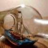
Hi Daniel -
What a treat to see a real miniature of the model I am working on. You are really capturing the essence of the ship in a really tiny way.
As for scale, my model will be 36.5 inches when measured on perpendiculars from the top of the taffrail to the front of the stem, which is what I see for your model. Multiplied by my scale this gives a length for the actual ship of 1314 inches, or 109.5 feet. If your model is one inch long, give or take a bit, I don't think you would be far wrong to say that it is 1:1250, which is a common miniature scale.
I've bookmarked your build and look forward to future installments.
Happy Thanksgiving to you and yours.
Dan
-
 shipmodel got a reaction from aviaamator in Queen Anne's Revenge 1710 by shipmodel - FINISHED - 1/36 scale
Hi all - thanks for looking in.
Another week, another report. The hulls are not going as well as could be hoped, so here is another deour.
To go with the tops that were built last time, I am now making the masts. I took a plank of rock maple and cut it down to the dimensions of the masts and spars that I measured from the Budriot plans. They are cut as square sticks sized to the largest width of the ultimate mast or spar, then cut to length. As long as I was cutting, I cut duplicates for the two models. Here are most of them, from the 5/8” x 19” of the main mast, down to the 3/16” x 6” of the main stunsail boom.
These were all cut on a Hegner Mk 4 multi-tool. It is a mid-sized tool that fits between the Preac and a full sized table saw, and is perfect for the size of the QAR models. It has a table saw, router, disc sander, and a Jacobs chuck that can power a flexible shaft grinding tool or an add-on lathe unit. I picked it up used and it came without an instruction manual, but I am figuring it out as I go.
After all of the pieces were cut, I turned first to the main mast. It is a fairly simple tapered cylinder. I planned to use the lathe on the Hegner, but it will only take 12” work pieces, not the 19” of the mast. Without access to a larger one I went back to basics to carve the mast.
The first step was to cut the tenon for the mast cap while the blank was still square. The blade height and rip fence were adjusted on the table saw and the tenon was quickly cut out on all four faces. Then the blank was made octagonal. This was done in the usual way by marking out the 2-3-2 divisions down the length of the blank with a dividers. With a sharp block plane the corners were taken down to the lines, resulting in the eight sided stick on the right.
After the corners were marked up as sight guides, they were taken down and rounded with a coarse disc in a hand-held random orbit sander. I didn't find it difficult to do this, since it only had to be accurate enough for a first approximation. I paused frequently to mark up any high spots that I felt when I spun the blank between my fingers. Then they were sanded down and the process was repeated till it felt round.
Once the round blank was achieved I went to the plans and determined that the diameter just under the cap was 7/16”. This was marked onto the top of the mast using a circle guide. Using a coarse sanding drum in the Dremel I took the mast down to that size in a sharp taper right at the top. I would pull the drum towards me, grinding off a thin slice from the mast, then rotate the blank a little and repeat. One corner of the top tenon was marked so I would not forget to make a complete circle before checking my progress.
From there I moved down the length of the blank: grinding a strip with the dremel and turning the blank a little bit, grinding and turning, grinding and turning. In essence, I became a very slow lathe. After doing this for a while I would smooth out any humps and hollows that developed by sanding the blank on a sheet of sandpaper which has been glued to a piece of plexiglass laid flat of the workbench.
This process would have taken much longer if the mast had a straight taper from base to cap. However, the plans had these two little beehive drawings which had to be the tapering diagrams. They were only designated ‘a’ and ‘b’, but after comparing them to the plans I determined that the one on the left fits the three lower masts, while the one on the right fits only the bowsprit.
This tapering process continued for what seemed like a very long time until I could slide the mast up through the top with the masthead extending above the top as indicated on the plans.
Now the pieces to support the crosstrees and top were made. Unlike English practice, there are no hounds, cheeks or bibs. Instead, the French at the time used only a front fish that fit to the mast and slid up between the crosstrees. A two-part bolster was fitted to each side and treenailed to the mast and to the front fish. Here are the plans.
The fish was made out of pear and treenailed to the mast with walnut dowels for contrast. The fish is also held in place by a pair of wooldings that lie in broad grooves carved into the face of the piece.
The bolsters are also pear and treenailed with walnut. The only technical point here is that it was made in one piece, not two. The staggered separation line was drawn on in pencil, then the back of a #11 blade was used to scribe the lines, which tattoos the pencil marks into the wood.
The mast is reinforced by alternating iron mast bands and wooldings. The bands are made from 1/16” wide brass strips which are wrapped around the mast and sized to fit, then chemically blackened. They are attached temporarily with glue before holes are drilled for metal pins. Each end of the strip where they meet gets one, and a third is placed on the opposite side of the mast. The pins are annealed iron wire which is inserted, glued, and clipped short before being peened smooth. You can see one on the band near the bottom end of the front fish and another just below the light reflection on the other band.
Working in a large scale like 1/36 will allow me to build some details much as they are made in full sized practice. The wooldings are a case in point. A cherry strip was cut, soaked and bent around the mast before being glued in place. 3” rope (1” diameter) is wrapped 13 turns around the mast, packed tightly against the wood strip, and cinched tight. A second cherry strip is added to the other side of the wrapping. A painting of dilute PVA glue secures everything. Once the glue is dry, everything was given a coat of the finish and rubbed down.
The top was fit back on the masthead to see that everything fit properly. The inset shows how the front fish comes up to the level of the top of the crosstrees and takes the place of the spacer that, in English practice, separates the masthead from the heel of the topmast. There is a third mast band that should be around the masthead just above the top, but the platform would not fit around it so it was removed until the top is permanently attached to the mast. [sharp eyes will also notice that the crowsfoot holes are towards the back of the mast. This will be turned around before the top is attached].
So here are two of the shipyard workers just skylarking on the main top. One seems to see a friend on the ground.
It’s a good thing that Dread Pirate Peter hasn’t spotted them. He has some pointed questions to ask about the location of crowsfoot holes. And why the bands and wooldings stop halfway down the mast.
Auf wiedersehen . . .
Dan
-
shipmodel got a reaction from CiscoH in US Brig Oneida 1809 by rlb - The Lumberyard - 1:48 scale - POF - Lake Ontario Warship
Hi Ron -
Just found and finished reading your log. You are making great progress and I really like the way you constructed the capstan.
I got interested in Oneida some years ago, and ultimately did a lot of historic research on the First Battle of Sackett's Harbor, which was the first naval battle, and may have been the first of any battles in the War of 1812. Quite a significant little scrap, which kept the British/Canadians from taking control of the Great Lakes. Oneida's gallant captain, Commander Melancthon Woolsey, is a true unsung hero.
I also built a 1/96 scale model of her per Chapelle's plans. It has the raised deck and pivot gun, later removed by Woolsey. After I found that piece of information construction was halted, and other projects have prevented completion of the masting and rigging. Here are a few photos for comparison, if they are of any help to you.
Be well
Dan
-
 shipmodel got a reaction from src in US Brig Oneida 1809 by rlb - The Lumberyard - 1:48 scale - POF - Lake Ontario Warship
Hi Ron -
OK, I set up an album in the completed scratch-built forum under the title "Oneida (1809) US brig of war". I hope the photos are useful. Let me know if you have any questions.
Continued success with your work.
Dan
-
shipmodel got a reaction from mtaylor in US Brig Oneida 1809 by rlb - The Lumberyard - 1:48 scale - POF - Lake Ontario Warship
Hi Ron -
OK, I set up an album in the completed scratch-built forum under the title "Oneida (1809) US brig of war". I hope the photos are useful. Let me know if you have any questions.
Continued success with your work.
Dan
-
 shipmodel got a reaction from hexnut in US Brig Oneida 1809 by rlb - The Lumberyard - 1:48 scale - POF - Lake Ontario Warship
Hi Ron -
OK, I set up an album in the completed scratch-built forum under the title "Oneida (1809) US brig of war". I hope the photos are useful. Let me know if you have any questions.
Continued success with your work.
Dan
-
 shipmodel got a reaction from BETAQDAVE in US Brig Oneida 1809 by rlb - The Lumberyard - 1:48 scale - POF - Lake Ontario Warship
Hi Ron -
Just found and finished reading your log. You are making great progress and I really like the way you constructed the capstan.
I got interested in Oneida some years ago, and ultimately did a lot of historic research on the First Battle of Sackett's Harbor, which was the first naval battle, and may have been the first of any battles in the War of 1812. Quite a significant little scrap, which kept the British/Canadians from taking control of the Great Lakes. Oneida's gallant captain, Commander Melancthon Woolsey, is a true unsung hero.
I also built a 1/96 scale model of her per Chapelle's plans. It has the raised deck and pivot gun, later removed by Woolsey. After I found that piece of information construction was halted, and other projects have prevented completion of the masting and rigging. Here are a few photos for comparison, if they are of any help to you.
Be well
Dan
-
 shipmodel got a reaction from garyshipwright in US Brig Oneida 1809 by rlb - The Lumberyard - 1:48 scale - POF - Lake Ontario Warship
Hi Ron -
Just found and finished reading your log. You are making great progress and I really like the way you constructed the capstan.
I got interested in Oneida some years ago, and ultimately did a lot of historic research on the First Battle of Sackett's Harbor, which was the first naval battle, and may have been the first of any battles in the War of 1812. Quite a significant little scrap, which kept the British/Canadians from taking control of the Great Lakes. Oneida's gallant captain, Commander Melancthon Woolsey, is a true unsung hero.
I also built a 1/96 scale model of her per Chapelle's plans. It has the raised deck and pivot gun, later removed by Woolsey. After I found that piece of information construction was halted, and other projects have prevented completion of the masting and rigging. Here are a few photos for comparison, if they are of any help to you.
Be well
Dan
-
shipmodel got a reaction from mtaylor in Bristol Pilot Cutter by michael mott - 1/8 scale - POF
Michael -
Teriffic woodworking on the cabin. The huge 'sanding stick' is an elegant solution to the problem. The joinery is superb. You should consider submitting some photos to Fine Woodworking for their Reader's Gallery.when you are done.
Thanks for sharing, as always.
Be well
Dan
-
 shipmodel got a reaction from Martin W in US Brig Oneida 1809 by rlb - The Lumberyard - 1:48 scale - POF - Lake Ontario Warship
Hi Ron -
Just found and finished reading your log. You are making great progress and I really like the way you constructed the capstan.
I got interested in Oneida some years ago, and ultimately did a lot of historic research on the First Battle of Sackett's Harbor, which was the first naval battle, and may have been the first of any battles in the War of 1812. Quite a significant little scrap, which kept the British/Canadians from taking control of the Great Lakes. Oneida's gallant captain, Commander Melancthon Woolsey, is a true unsung hero.
I also built a 1/96 scale model of her per Chapelle's plans. It has the raised deck and pivot gun, later removed by Woolsey. After I found that piece of information construction was halted, and other projects have prevented completion of the masting and rigging. Here are a few photos for comparison, if they are of any help to you.
Be well
Dan
-
 shipmodel reacted to michael mott in Bristol Pilot Cutter by michael mott - 1/8 scale - POF
Thanks for the compliments Elmer , and Crackers.
I have been thinking about my build entries and like the style that Ed Tosti uses for his entries so I am going to see how it works from here on the numbers are starting at number nine because I have made 8 posts recently regarding the cabin structure. I will follow a similar pattern for different areas in the future.
Cabin Structure. part 9
After gluing up the sides and beams I noticed that I had not done as good a job making the beams line up on the top profile and this caused a problem with the gluing of the planks. My solution was to sand down the sides and ends to match the middle beams rather than removing the beams. this then ensured that all the curved surfaces were identical.
I made a long sander with some 220 grit and carpet tape strip of oak.
I used the narrow side first then the wide side to finish, i did not see the need to go any finer than the 220 grit because all the surfaces will be covered with glue and other wood.
This allowed me to set some new pine strips that were all the same thickness as the fir planks. These strips were glued to the perimeter and across the separation beam.
The fir planks will be pre drilled for the "screw plugs" (small dowels) before being glued to the top then the dowels and caulking before fitting the companion way slide logs and hatch.
Michael
-
 shipmodel got a reaction from druxey in Bristol Pilot Cutter by michael mott - 1/8 scale - POF
Michael -
Teriffic woodworking on the cabin. The huge 'sanding stick' is an elegant solution to the problem. The joinery is superb. You should consider submitting some photos to Fine Woodworking for their Reader's Gallery.when you are done.
Thanks for sharing, as always.
Be well
Dan