HOLIDAY DONATION DRIVE - SUPPORT MSW - DO YOUR PART TO KEEP THIS GREAT FORUM GOING! (89 donations so far out of 49,000 members - C'mon guys!)
×

hollowneck
-
Posts
1,589 -
Joined
-
Last visited
Content Type
Profiles
Forums
Gallery
Events
Everything posted by hollowneck
-
 ...as Reverend Ron Hollowneck is fond of saying: "Hallelujah!"... you're doing a fine job and this model is turning out nicely. I like it.
 -
Ditto! Very nice work, clean with a good eye for the artistry these models beg from their builders. Cheers to a model that will be beautiful once she's rigged and marauding in the Med!
- 208 replies
-
- 3
-

-
- kitbashing
- Woodcarving
- (and 4 more)
-
Yikes! Good recovery, Bob. There is a subdeck (orlop) that slides into place around the bulkheads on the Vanguard Sphinx build and the fit is also very tight owing to the manufacturing tolerances that I've been praising. However, it didn't require the number of bulkheads you had to accommodate in this build. The stem & the stern pieces: tricky - and fragile - business! You should be o.k. now. Watch those elbows...😖 Do flip ahead in the kit's manual and scrutinize the plans BEFORE proceeding in a logical manner. It's the logic that sometimes defeats us!
-
You caught the upside down "N" cock-up - Good! Glad you fixed the "X" too...🤣... Very nice work. This is an advanced kit build and you're doing a great job for only your second wooden model ship.
-
Bob, the Vanguard HMS Flirt is a great choice for your Build Log. The kit's materials and the "Build Manual" are excellent. I'll follow along. There are a host of superb modelers here that will be your willing - unpaid- consultants! AND - As we all know, there is no imperative to speed through your build, no "timeline" on the enjoyment of your achievement. You'll find that the additional time in cataloging your progress with photos, text commentary - and questions you'll post here to other colleagues - will increase the build time substantially. However, besides the obvious benefits of encouragement and encyclopedic knowledge (and help) from others, you'll be your own worst critic when you focus on posting your work for others to see. For me, this aspect of creating a Build Log has been rewarding since a 500% enlargement of one's work can be a humbling reminder why we are all learning and perfecting.
-
Nice work, Glenn. You've done a superb job, especially on all the joinery as well as the finish. Liquitex Crimson was also my choice for the gunports and inner bulwarks for my HMS Sphinx/Camilla build. As you know, acrylics dry a little darker - and a little bit of red goes a long way! Ron
- 840 replies
-
- 4
-
-
- winchelsea
- Syren Ship Model Company
- (and 1 more)
-
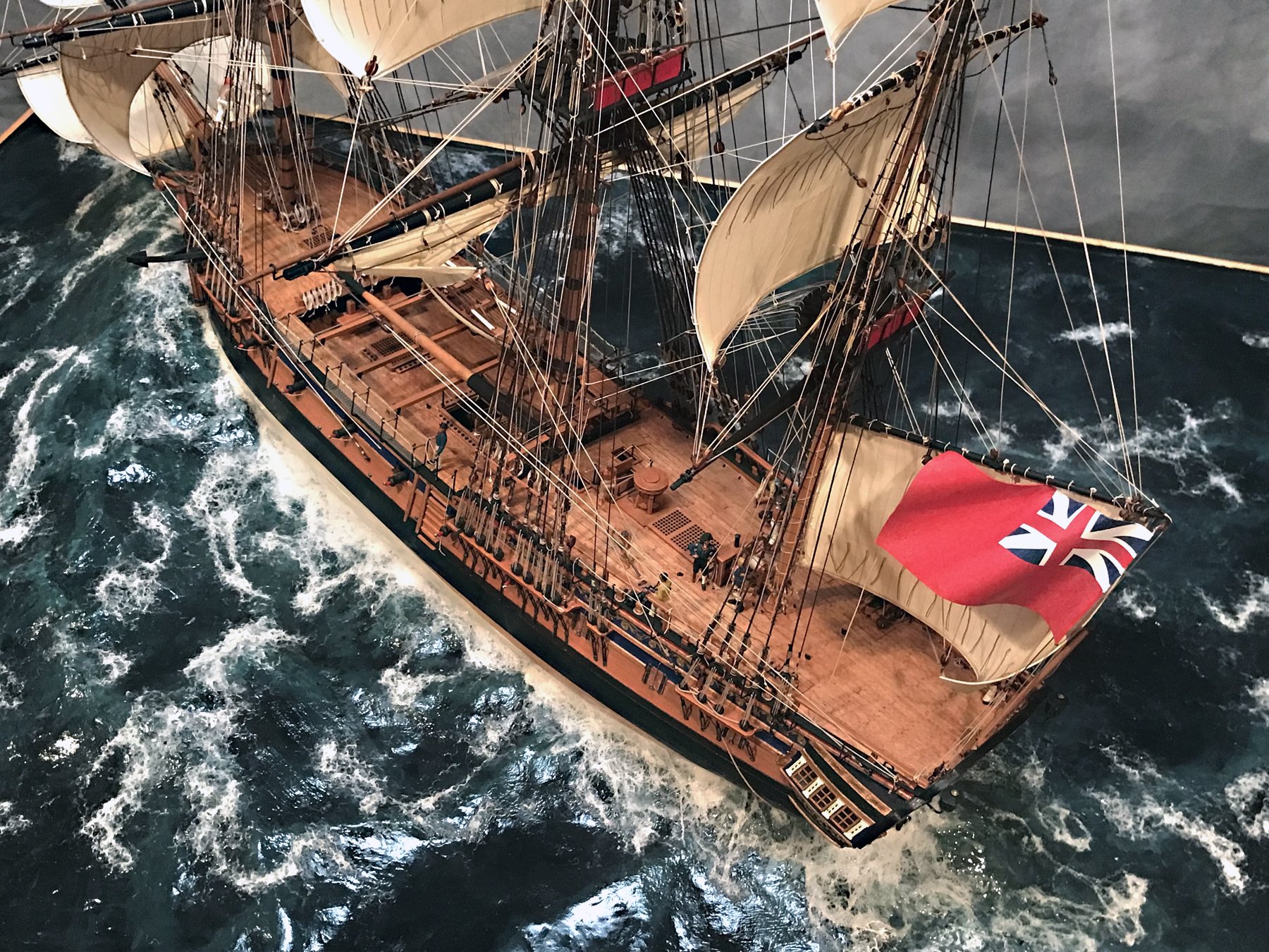
Thanks you BobG, Rustyj - and those who are following my build. Your encouragement is much appreciated. Rigging "gives life" to a sailing ship, as it should. Convincing sails with their proper rigging (whether furled, set, or a combo of both states), also "kicks things up a notch" ..as TV Chef Emeril LeGasse' used to say. I've mentioned here before, but I'll say it again: I especially like these complex rigging steps. For me, creating a convincing looking model of a large sailing ship depends significantly on the execution of all the "strings." Despite this very methodical, engineering and physics-oriented task, a complex rigged ship can be a dramatic artistic statement at the end of the day. With saying this, it's not meant to diminish a more spartan execution of a Royal Navy dockyard-style one. "...the noblest and most beautiful work of man, a ship." - J.H. Craine, London, 1948, Ship Modelling Hints & Tips Glenn - I've always rigged the principal stays first, although the backstays get rigged when I do the shrouds. I like to set the mast positions first at this early stage, then proceed to precisely align them when subsequently mounting the shrouds. Some builders like to rig shrouds off the model, then mount them and then add all the stays. Not for me. One of the benefits of my sequencing is that virtually all rigging lines - but particularly the standing rigging - are presented very taut, as they should be. On the other hand, if one follows the rigging plans as numbered in the kit, a nicely rigged model can be accomplished. I have merely taken a couple of Chris' clearly drawn and detailed rigging plan sheets out of sequence. Ron
- 542 replies
-
- 10
-

-
-
- Sphinx
- Vanguard Models
- (and 3 more)
-
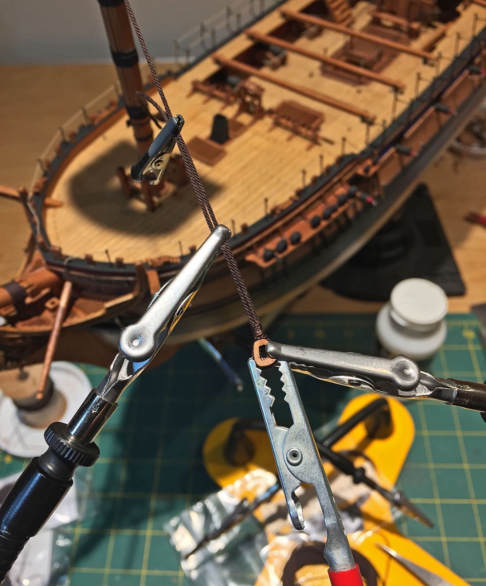
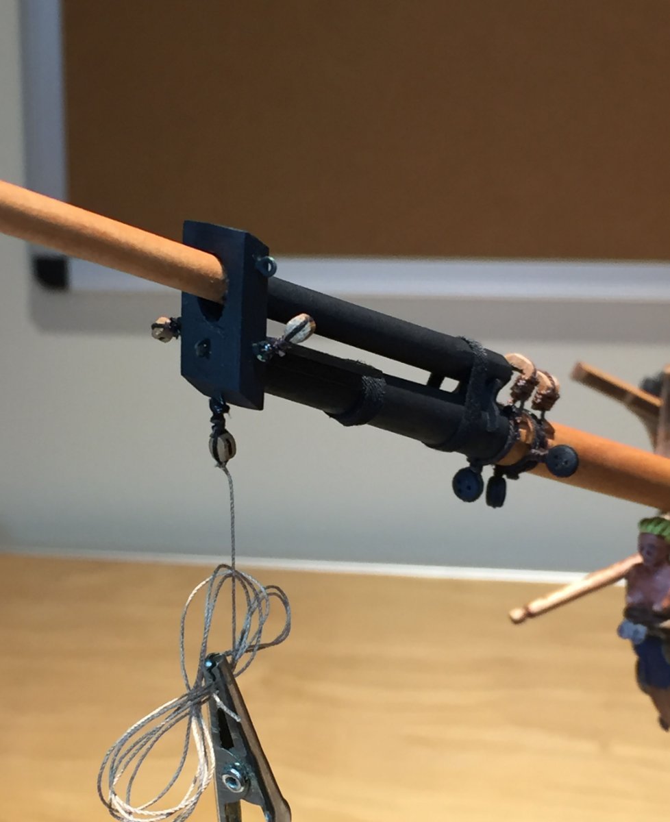
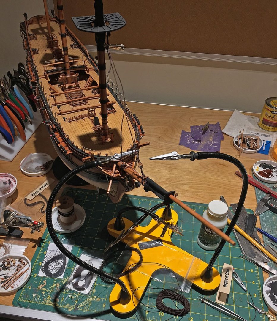
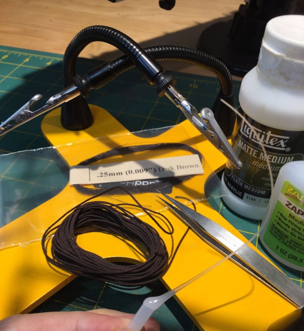
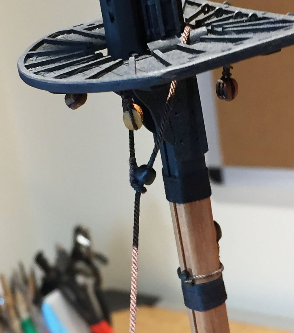
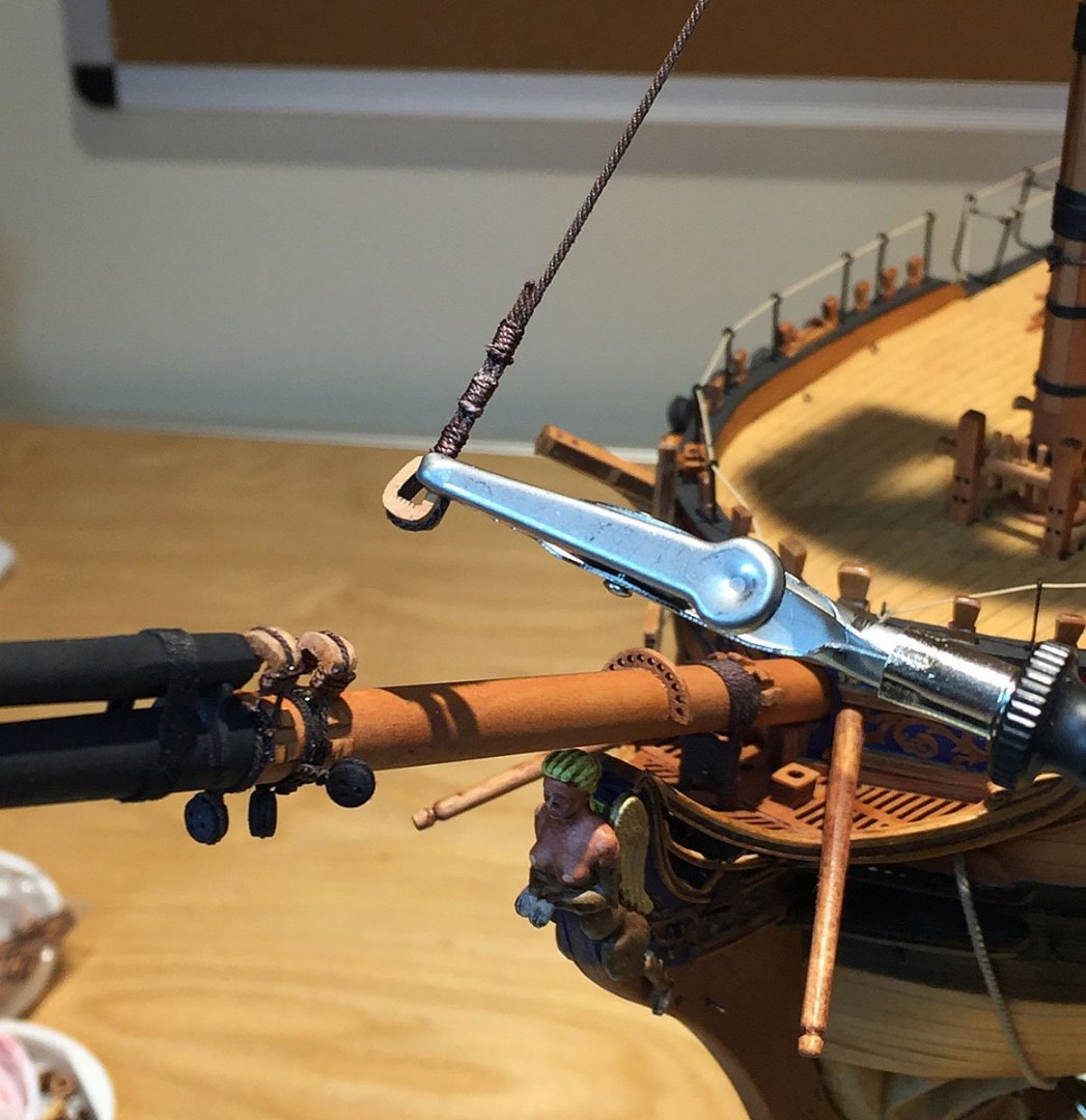
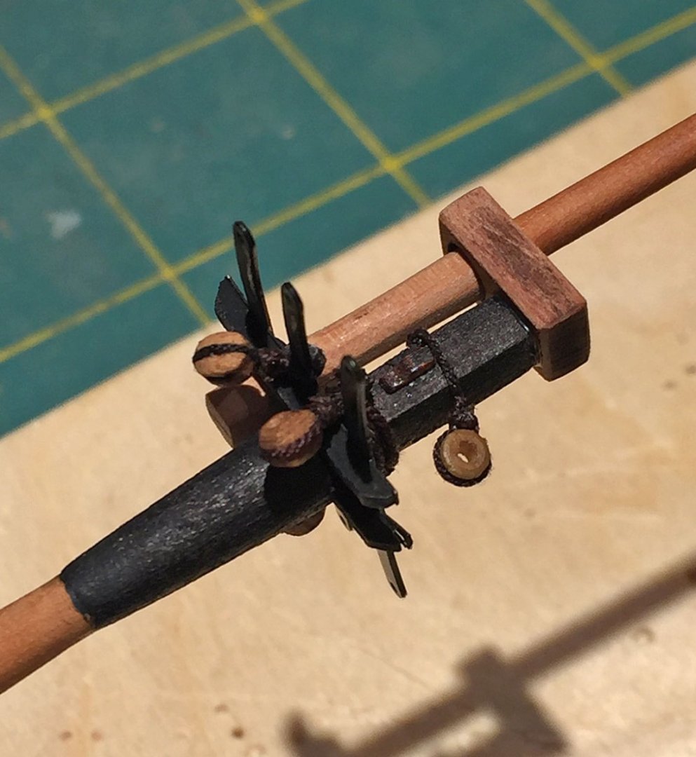
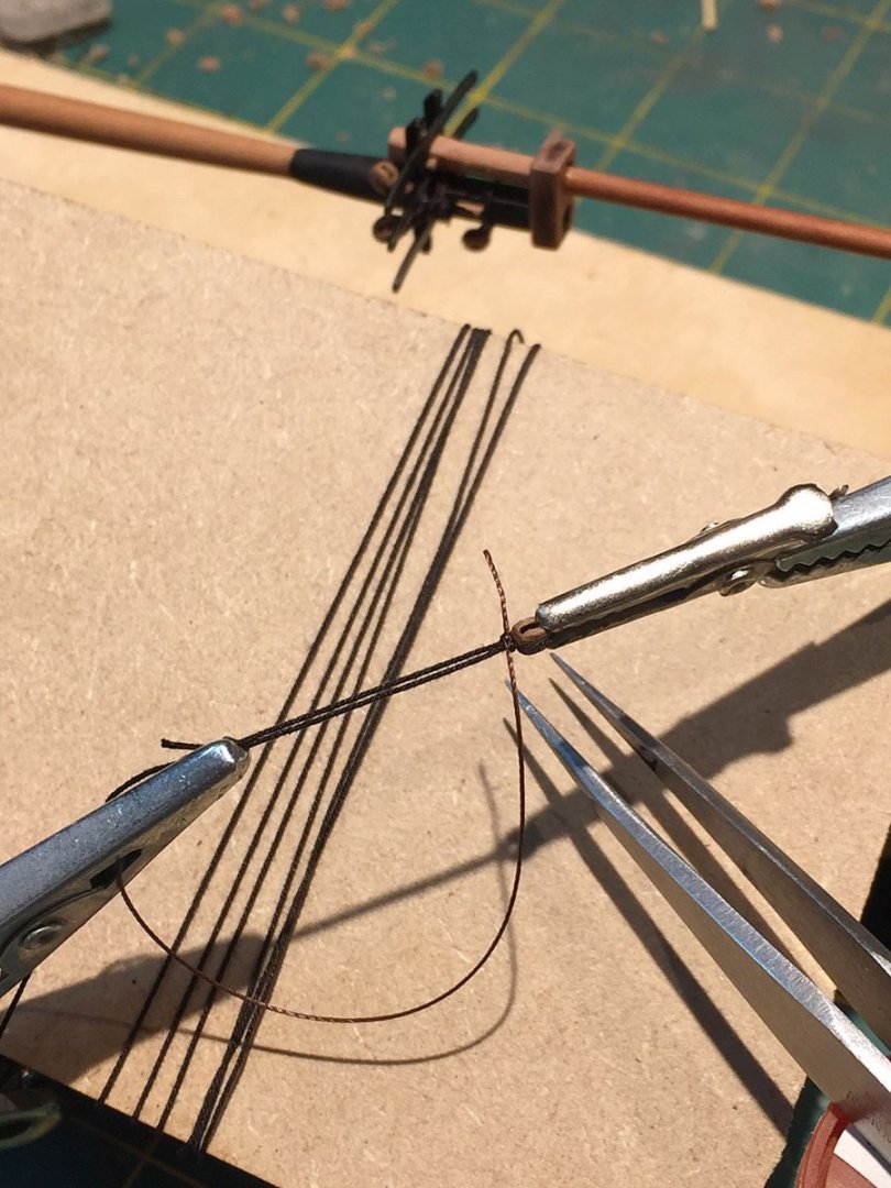
🎼 Rig, rig, rig your boat, gently - or you'll scream. The "rig station." This looks messy, but most everything in the foreground is readily at hand for making the foremast stays. The large, alien-looking yellow tool is a "QuadHands", my four-armed, extremely flexible helper. Its base is quite heavy so it stays put where you place it (unlike its smaller third-hand cousin, seen skulking-off to the left). In the following photos you'll see different combos of small clamps (QuadHands ones plus others) that help to keep rope lines straight and taut while others hold various tackle in place, like open and closed hearts. Here the foremast stay rope is pulled taut and wrapped around a closed heart block (6mm). The first of three stroppings is shown tight to the block's head. Adding a number of clamps helps me set up these blocks nicely. There are numerous methods, techniques to accomplish rigging. No two ship model builders will do these tasks in the same way. The steps (and tools) here are one approach that has worked well for me. The basic materials and tools for the lower mast standing rigging: a long TFE nozzle for depositing miniscule spots of CA where needed, Matte Medium acrylic used as an adhesive for some aspects of affixing rigging, two sizes of dark brown (tarred) rope for the mast stays, and the QuadHands jig. Oh yeah: very pointy tweezers. The bowsprit is loaded up with her tackle blocks: deadeyes, open hearts, single sheave blocks. The foremast stay and preventer ropes wrap around the lower mast's bibbs, over the bolsters and loop around the hounds (the square section). I created a simple "eyesplice" to tension the rope termination against its "mouse." The mouse piece provided in the kit is a shiny black, slightly elongated bead. I've created my own "mice" with small carved pieces of wood in past builds but this one will do the job - after it gets painted with flat black so it's not shiny. There are two of these (identical with the lower main mast) and the "collar and mouse" will both tuck closely beneath the tops and frankly, they get visually "lost" in the mass of rigging lines that are arrayed in this area. Some same era MSW modelers will note that I don't "serve" my standing rope lines; although it's more historically accurate and yet another level of detailed execution, I don't attempt this on 1:64 models. If HMS Camilla were a 1:48 scale kit, that would be a different ballgame and I'd add a significant number of additional steps to my build, especially with rigging. This previous point is a personal hobby philosophy. I don't like to exceed 8-10 months on any specific build. Especially now since I'm interested in the challenges of making dioramas for my models that adds a considerable amount of time to each artwork. There remain a large number of (sailing ship) models I'd like to build before my eyes and hands won't permit me to accomplish what I envision in my mind. Life's short. That's my excuse - and I'm sticking to it! I've positioned the closed heart rigging block that's been stropped to the fore stay with a holding clamp from the QuadHands; the jig has two long arms ( about 12") with adjustable, locking alligators. The multiple arms are super-convenient for this specific rigging work. Note that the closed heart block is in position to be lashed to its open heart mate already tied and positioned on the bowsprit. Also note that the rigging rope is "tensioned" with the quad's clip and not in the way of working the lashing line through the opening. The blocks are now lashed (and frapped), 4 turns each. The end of the thick stay rope has also been stropped with three turnings of .20 brown thread (not rope). The toothpick is shown just before applying a tiny spot of matte medium acrylic to the end of the tied back rope end to prevent it from coming unravelled. The acrylic adhesive will dry transparent, not shiny. After a second fore stay (the preventer) is mounted to the lower mast and bowsprit in an identical fashion (the second closed heart block can be seen here behind the completed fore stay), I will rig the two bobstays that run from under the bowsprit downward to the stem. I do these next to even out some of the tension created by the upward pressure from the upper stays. The foremast is mounted securely now and should be near perfectly perpendicular to the waterline. Once the main's topmast is rigged to the lower foremast, the fore will pull aftward ever so slightly - which is the desired angle, fore-to-aft. Don't worry about the starboard-to-port angle of the foremast just yet; it will get properly positioned once its shrouds and stays are added. Ron


- 542 replies
-
- 26
-
-

-

-
- Sphinx
- Vanguard Models
- (and 3 more)
-
If you need to scratch pieces that are curved - like the small volutes, or the über-delicate half-section of plain rail that falls over a hawse opening - I'd suggest the obvious: use some of the pear laser sheets (1mm or 1.5mm) for this. I did this in one area for my rails. I'll try to remember to get a closeup photo. This part of the kit's design seems to me to be an experiment. I believe the better solution would have been to supply a few sticks of pear strip stock and a brass scraper (in one of the thicker P/E frets); this solution would have handled the straight sections just fine. For the curvy rail bits, some 3D printed resin parts would do the trick, not lasered. I'd be surprised if Chris isn't taking notes for a V2.0 kit. Despite some of these admittedly small issues (the Devil's in the details), the kit still comfortably sits at the pinnacle of high-end kits. However - the Master Korabel ones (from Russia) aren't very far behind. Cheers! Ron
- 857 replies
-
- 3
-
-
- Sphinx
- Vanguard Models
- (and 1 more)
-
No wireless ear monitors. No guitar transmitter rigs. Full-throated singing. The LSO. John Hurt narration. And more! A 1987 video production of a musical, inspired by the Lewis Carroll (Alice Through The Looking Glass) book of 1896. And 35 years after this London musical, a wholly new definition of "Snark" has emerged. The book, available on Amazon... ...If—and the thing is wildly possible—the charge of writing nonsense were ever brought against the author of this brief but instructive poem, it would be based, I feel convinced, on the line: “Then the bowsprit got mixed with the rudder sometimes.” Watch this video comrades. You know, in your spare time. An hour well-spent on YouTube. Ron

- 186 replies
-
- 3
-
-
- keelless
- reverse clinker
- (and 4 more)
-
That's precisely what I did when I tackled this bit of the build, B.E. The char must be removed and it was a Royal PITA (pain in the ****) to get all these pattern pieces de-charred and subsequently mounted. One clever lasered rail turned into several fiddly pieces. Chop, chop. After doing this - per your illustration of a modification - I concluded (too late) that the best solution, which I didn't employ, was to scratch all of these bits. Nice 3mm pear stock. Nice new profiled scrapers. Voila'! Next time. Wait til' you get to the channel knees...🤨 Cheers, Ron
- 857 replies
-
- 5
-
-
- Sphinx
- Vanguard Models
- (and 1 more)
-
Thank You, TBlack. After reacquainting myself with the procedure (I've done this before, but it's been awhile), it just required patience to proceed slowly, methodically. The most difficult aspect is threading the line upward through the headrail slots and keeping the rope taught so it didn't slacken between turns. Hint: I used a small clamp on the edge of the stem to hold the rope taut as I fished the end through the slots. The gammon rope needs to be quite long ( for this build, about 48") which means it will inevitably want to tangle itself around something, typically one of the bumkins. Also, after I'd completed the turns around the bowsprit with all looking even and tight I took a break and clamped the still lengthy rope to the stem's edge. I returned a while later and did the horizontal frapping, with physically "fresh" fingers - and mentally, unencumbered! Like so many aspects of proper square-sailer rigging, proceed slowly for the best - and most satisfying- results. Haste really does make waste. And, I will add: anxiety if one is in a hurry. No swearing. Honest. Just holding my breathing every so often to steady my hands... which is also a good technique to employ when you do delicate, critical painting too. Ron
- 542 replies
-
- 4
-
-
- Sphinx
- Vanguard Models
- (and 3 more)
-
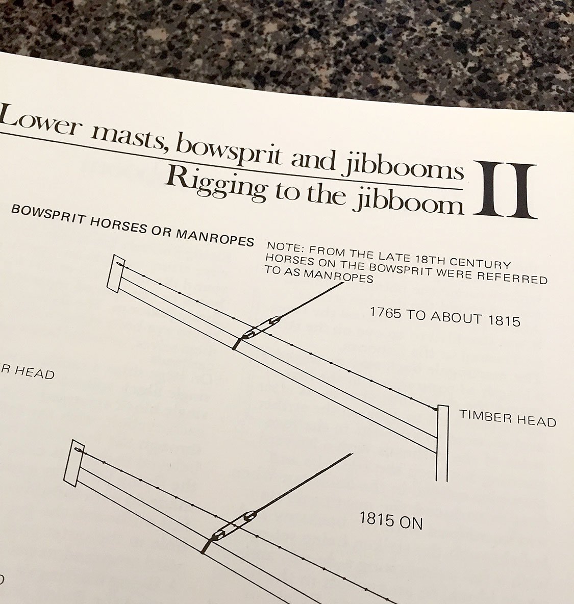
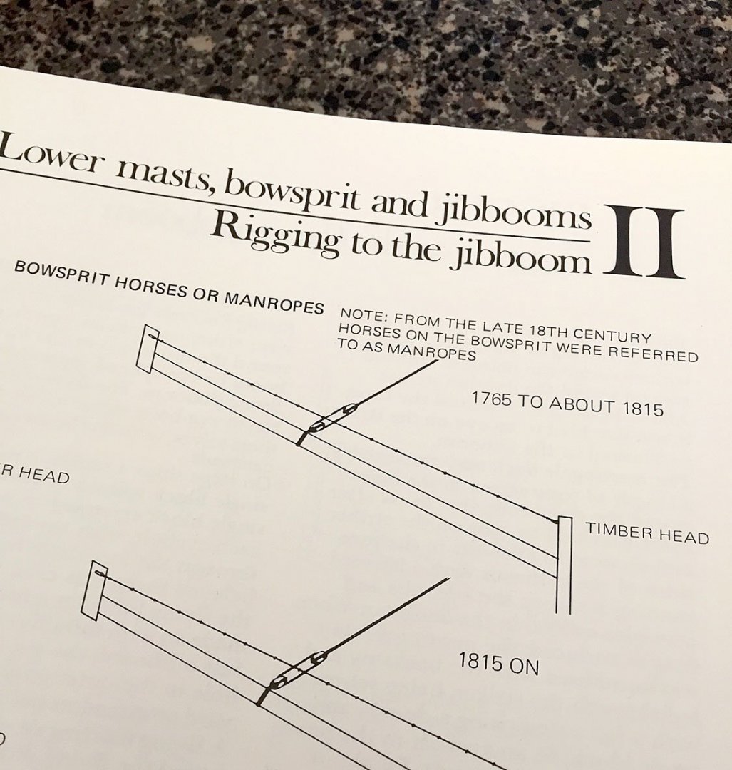
...good catch. I'm getting the impression that following Lees is a little like interpreting the Dead Sea Scrolls...I'll drop the knots on the manropes and add footropes along the jibboom. Yay! Ship modeler "tech talk!" Thanks, seriously. Thank you B.E. & tomganc, appreciate your comments. Ron
- 542 replies
-
- 2
-
-
- Sphinx
- Vanguard Models
- (and 3 more)
-
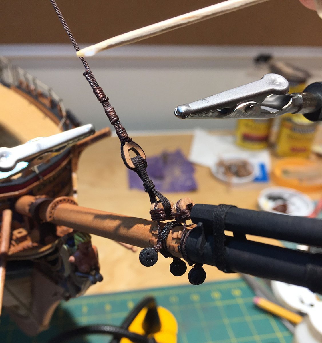
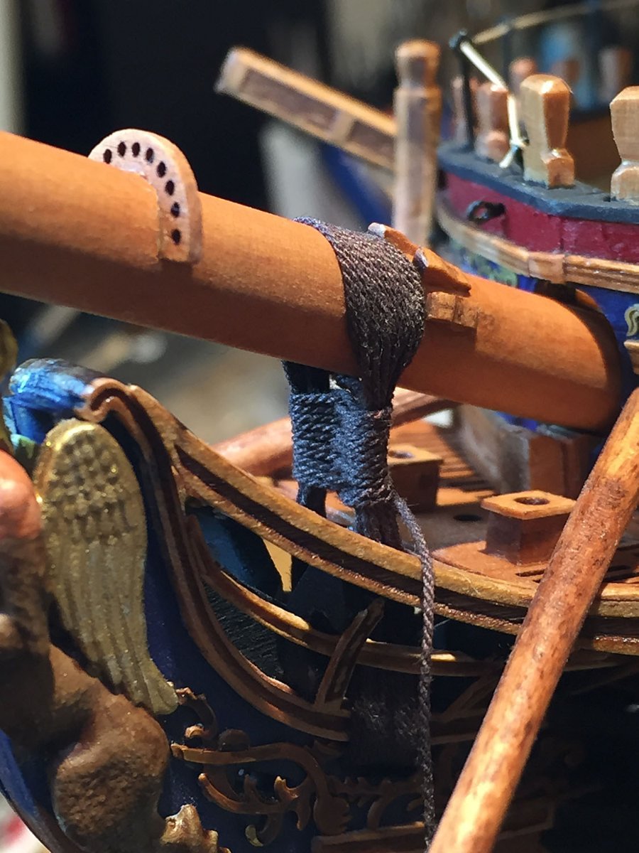
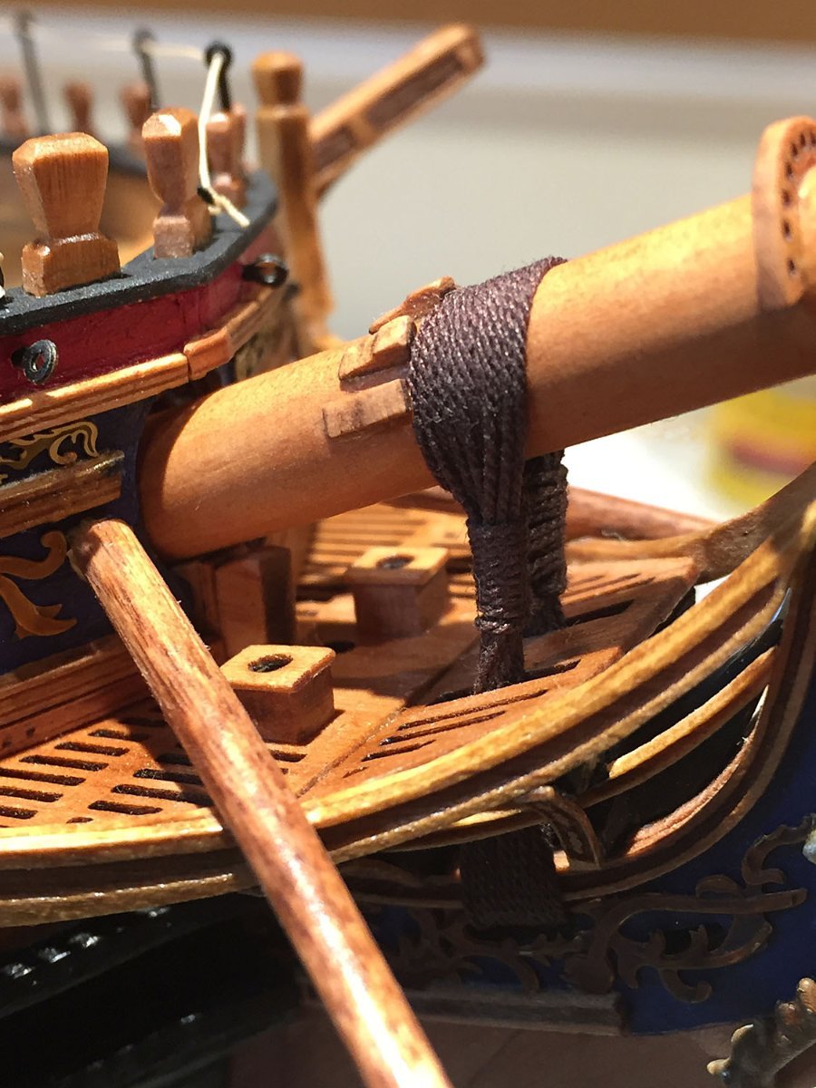
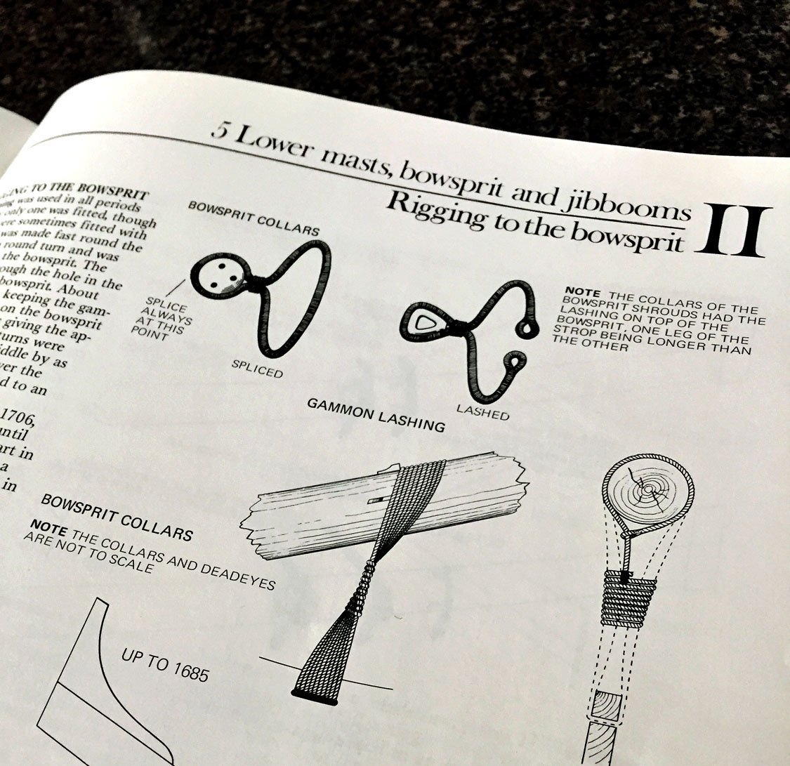
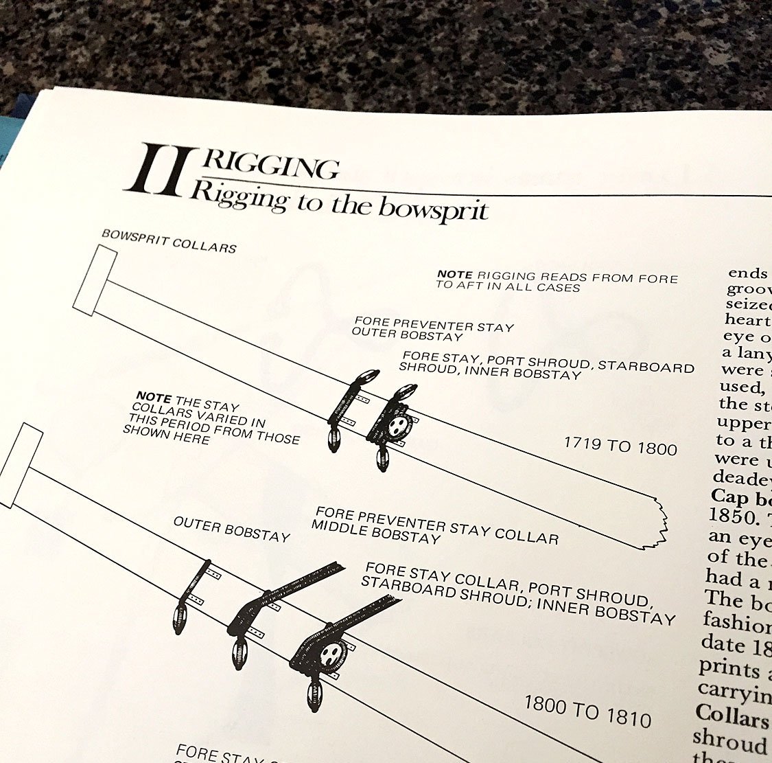
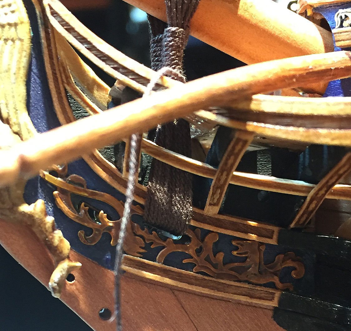
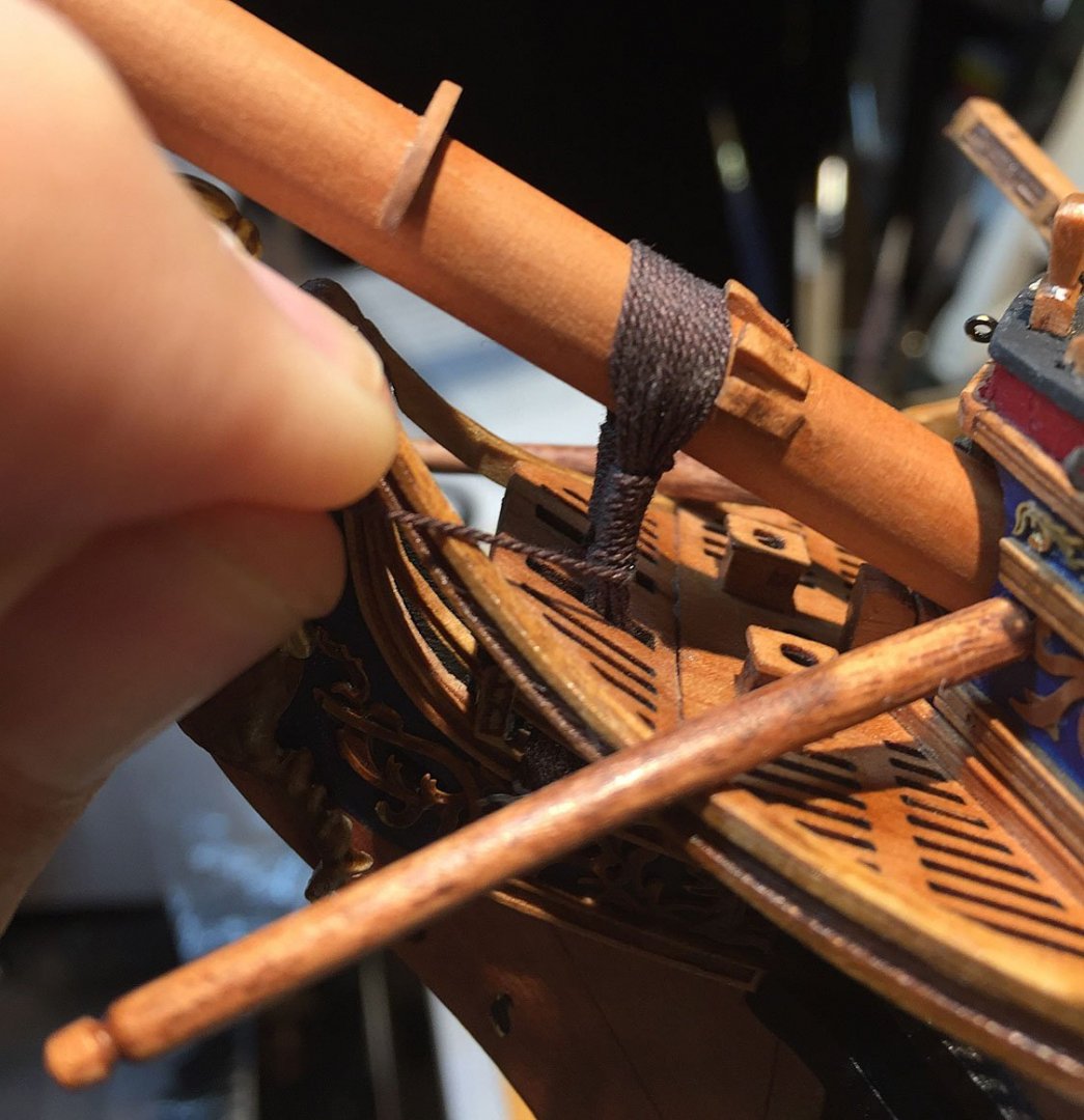
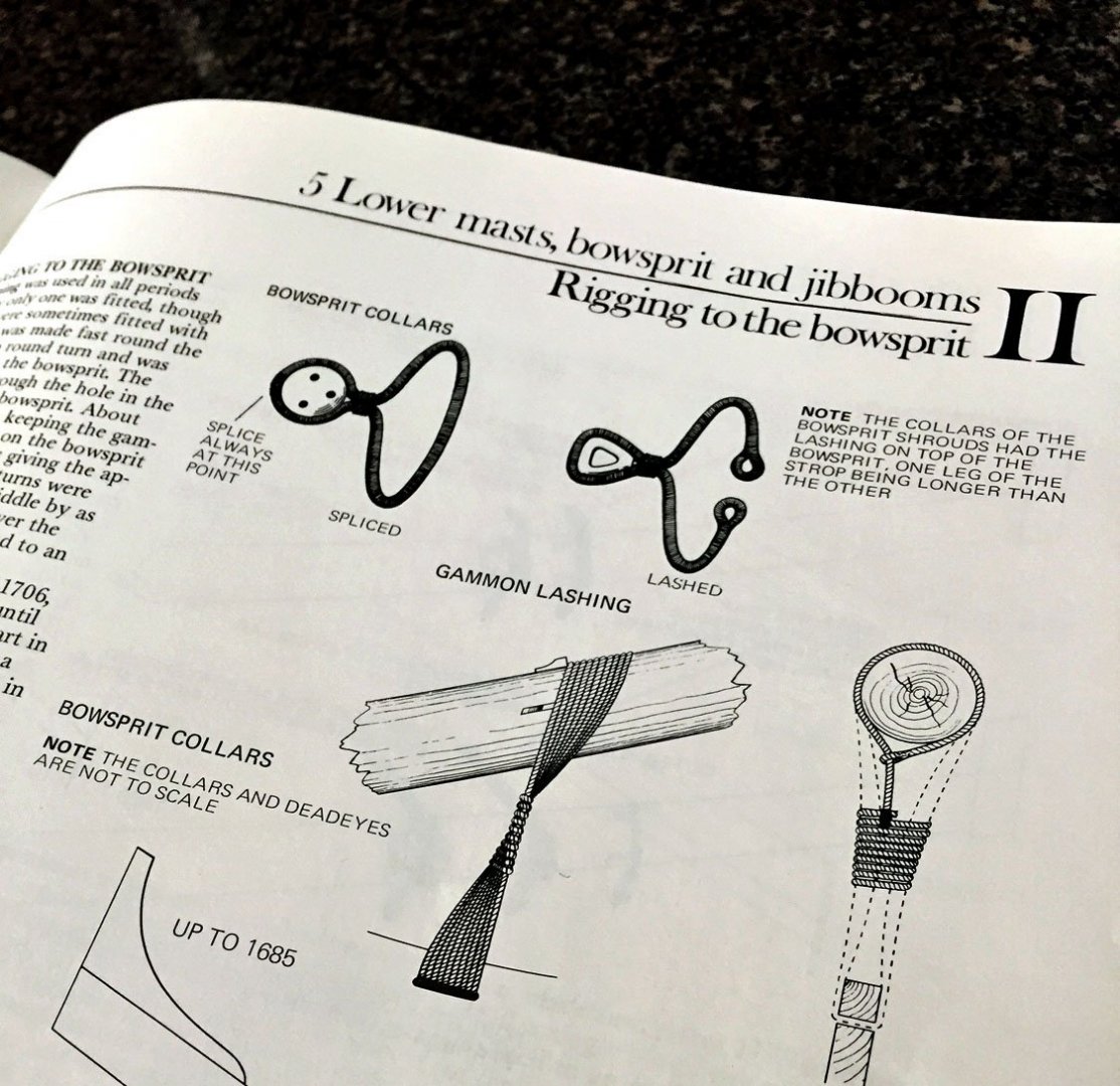
Details: Gammoning & Frapping. Now that all the masts are completed with topgallants - with their rigging blocks in-place - it's time to take care of business on the bowsprit before commencing other rigging work. A detail on gammoning of the bowsprit. I've used .5mm dark brown (tarred) rope for this rigging. There are eleven turns up against the cleats and down through the openings below the head rails to the stem slot. I pulled each rope turn tightly before threading the next turn. The gammoning rope turns will fill the stem slot; this looks straightforward to do. It is NOT. Below I've attached a photo from "Lees" rigging book to illustrate that the rope crosses over its previous turn with each successive one which results in a "twisting"arrangement. This entire procedure of rope wrapping also resembles "weaving" - of a sort. My completed "gammon lashing" of the bowsprit. These ropes were critical for securing not only the bowsprit (and its spritsails) but also the fore and main mast stay rigging ropes; the thick support ropes (standing rig) exerted tremendous upward strain on the bowsprit. In addition to "looping" each successive rope turn over the previous one and once the vertical threading was complete, the rope was then horizontally threaded tightly between and around the vertical rope turns. This second, contiguous rigging step is referred to as "frapping." The number of frap lacings were equal to the number of rope turns around the bowsprit, in this case: eleven. Gammon lashing and its frapping completed. The end of the rope is simply fed through a frapping turn as a hitch and tucked into the frapping and glued with a small drop of CA. I'm pretty confident 18th-C dockyard riggers didn't use CA to finish off this elaborate rigging process.🤪... A Lees book detail on gammon lashing. To the right, the cross section illustration shows a simple "eye splice" to START the gammon lashing. However, what the rigging "Bible" doesn't show is the critical step to alternately overlap each successive turn after its fed through the stem opening and back around for a successive turn. The illustration on the left does show the effect of crossing-over each rope turn: the forward-most turn is at the rear of the stem slot. Note that the stem slot is full. The next bowsprit rigging step; making-up and mounting the various stay collars and their deadeyes. There are lots of these blocks to make and mount. The cleats to support the collars are already in place from the earlier step to finish the bowsprit's woodworking (these small wooden cleats prevented the collars from slipping along the bowsprit). Once all the bowsprit's fore and main stay blocks are rigged (coming up soon), I'll mount some "manropes." This will be a hand-sized rope line from the bowsprit cap back to the fore timbers (both starboard and port). The ropes were for sailors to have a hand hold when they were at work on the bowsprit. Ron


- 542 replies
-
- 17
-
-
-
- Sphinx
- Vanguard Models
- (and 3 more)
-
Very nice work, B.E. The capping rail at the stern looms. I'll be interested to see how you approach finishing this tricky area - mainly, where to terminate the ends of the continuous capping piece - The roofline? The berthing rail? You did a much better job with your galleries than I did with mine. I'm tempted to rip-off both silly rail mouldings below the windows and scratch my own. Of course, this means ripping off the stern rails all the way across the counters in order to match the sections that will need to be mitered where they meet at the corners. Gulp. All this klugeing on my part is owing to the early misalignment of the stern pieces that shifted structural bits by a few silly millimeters. 😖 Instead of four rows of roof tiles (a very clever and nice use of the thin P/E), I could only fit three to make the top decoration align. BTW: I love the "light" that results from opening up the galleries with interior doorways. What a great hack for your open reveal. Ron
- 857 replies
-
- 2
-
-
- Sphinx
- Vanguard Models
- (and 1 more)
-
....a ship builder's PTSD: finishing your model. Pour yourself a wee dram o' scotch and congratulate yourself. Post-malaise, I run around the block three times and then peer into my stash. Ron
- 112 replies
-
- 1
-
-
- Cheerful
- Syren Ship Model Company
- (and 1 more)
-
You are too kind, druxey. I will note - with great irony - that your avatar is an upside down clinker hulled ship's boat! Ron
- 542 replies
-
- 2
-
-
- Sphinx
- Vanguard Models
- (and 3 more)
-
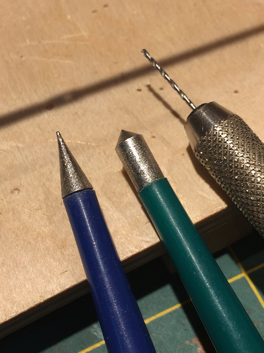
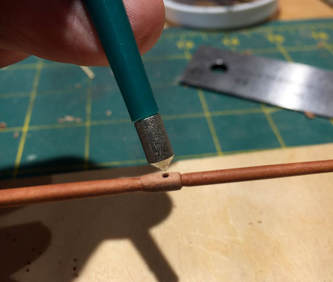
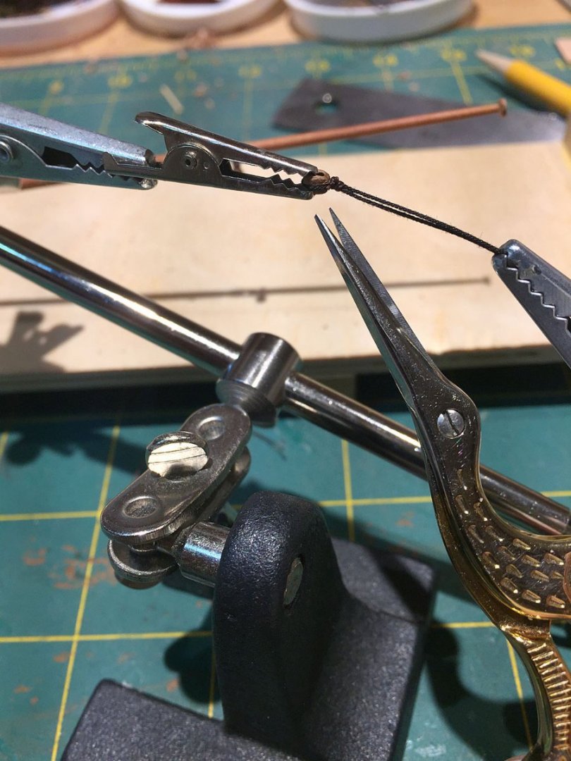
A little more progress on mast work, finishing-off the topgallants, some tools I use to prep them. There is a .7mm hole at the support for the top gallant yard tie. This "bulge" also gets blackened. I like to break the edges of small holes with a chamfer tool since my most used, small drill bits don't have the sharpest cutting tips and leave some "fuzz." I know, I need to purchase some more small drill bits. Speaking of... a .7mm drill bit in a pin vise and my two chamfer(ing) tools. Just a couple twists with either of these eliminates most wood fuzz. I believe I purchased these from MicroMark years ago but not certain, though. Inexpensive I recall. I've had them for years. Diamond cutting surfaces too. AH...the joy of having the right tools for the right jobs. Here is Camilla's foremast trestle and crosstrees with rigging blocks lashed. The thimble is a nice wooden one, 2.5mm, and is for the main topgallant mast stay. The little chock that holds the mast stay thimble in place is tiny. If you can't read the last word in that sentence you probably should be thinking about not doing rigging. Seriously, these itsy-bitsy chocks - all 182 of them provided in the kit, lasered in pear - are so small that when I sneezed (I'm nursing a cold), several that I'd cut out to prep literally disappeared - Poof! - forever gone to that place to hang out with sock monster, a close cousin. I've glued the topgallant mast into position and I'll blacken up through the mast cap next. I can't emphasize how important it is to mount all these mast rigging blocks in- advance of the stay and shroud line rigging. One wants to be mainly "running rope" at that stage and not fiddling with tying these rigging elements into place after-the-fact! Nothing too surprising here, however, I've learned to insert a smaller alligator clip into the larger one in my "third hand" - which is indispensable for rigging. I have a "Quadhands" also, but this particular work only needs two grippers to accomplish the task successfully. The single sheave, Falkonet pearwood block is 3mm. I refuse to rig any block smaller than this and I have 20/40 close vision!... I use .15mm upholstery thread typically (the brown line around the block mounting rope) to tie-off my blocks. The block's mounting rope is Syren's new "Ultra" dark brown. This rope's diameter is .20mm or .30mm, depending on the size of block or thimble. Like I demonstrated earlier I also pre-drill my block holes with a small thumbdrill. This saves so much hassle later. Anyone who's done rigging knows the trick to apply CA to the end of the rope line so it pokes through the holes more easily. In most cases, just opening up the tiny holes allows the end of most thin rigging rope to slide right through (but I still will use CA on some rope ends). Another not too surprising photo of repetitive rigging work. However, I've unveiled my secret rigging tool: my Gingher stork embroidery scissors. Yes, they are designed to resemble the bird's long beak. They are beautifully crafted, stay razor sharp ( I do hone them, but infrequently, as they're only used for rigging). They have comfortable finger holes in the blade shanks. The tiny cutting tips speak for themselves. I have two pair, both within easy reach on my bench. A good close-up cameo for the mini alligator block holder. A Breaking News update! Be careful if you're thinking about getting these Gingher scissors. There are several cheesy knockoff's on Amazon. The real-deal are about $18- $20. And worth every penny. More sneezing. More tissues. More rigging to do....Ciao, Ron

- 542 replies
-
- 14
-
-
- Sphinx
- Vanguard Models
- (and 3 more)
-
I know that feeling, except for me, it's rigging. Your woodworking joinery and finishing is top drawer. My brother is a master cabinetmaker and fine furniture artisan: for years I've known good woodworking when I see it! Just catching-up to your nice log. Ron
- 112 replies
-
- 1
-
-
- Cheerful
- Syren Ship Model Company
- (and 1 more)
-
Absolutely beautiful work. I could eat lunch (or dinner) served on that pristine deck! Someday I just might give it a shot and scratch build something in 1/4" scale. Ron
- 112 replies
-
- 1
-
-
- Cheerful
- Syren Ship Model Company
- (and 1 more)
-
Thanks, druxey. Leftenant Python just demoted him. The bosun is now that tar carrying the officer's honey bucket to the head... I suspected there might be a quick answer to my ships' boats query! Ron
- 542 replies
-
- 3
-
-
- Sphinx
- Vanguard Models
- (and 3 more)
-
Thanks Glenn for the commentary, the compliment on the masts. Going full-scratch on the masts/yards is the only way to approach a model of this quality IMHO. If one pursues a fully-rigged version I believe it to be mandatory to toss the walnut (but keep the excellent laser- cut top hamper pieces). I also have Flirt "on the shelf" and will likely build her in pear (my favorite)....depending on when the Vanguard Indy kit launches! My second ship model (2012) was the Caldercraft/Watton HMS Diana and then it was on to the Amati/Victory dockyards... I'm still undecided but I'm now leaning toward dressing Camilla's yawl with pear - per B.E.'s thoughts here. Of course, in the event, I would then add the kit's crutches to secure her upright amidships. Back to the sticks n' strings bench: one SyrenShipModels or Ropes of Scale string at a time for me. Ron
- 542 replies
-
- 4
-
-
- Sphinx
- Vanguard Models
- (and 3 more)
-
Ducati 1299 by Moonbug - Pocher - 1/4 Scale
hollowneck replied to Moonbug's topic in Completed non-ship models
Wow. This is an interesting approach and there is definitely some dystopian art going on here, a lot of attention to detail. A decrepit, abandoned Rolls in a barn: one wonders if this is a socio-political statement by the modeler? Going for $4,000 U.S. on eBay? Wow, again! Ron -
Yep, Glenn. I agree with your last words: if druxey doesn't know... At the end of the day (and this thread) I hope Goodshipvenus is enlightened and has enough info to decide what to do. Ron
-
I'll go with your hunch, druxey. and... or ...perhaps nothing more than "breaking wind." 🤣 This unexplained anachronism persists even with the kit's designer. I had no reservations about deleting this door/screen arrangement on my build. Ironically, most everything else about this kit is very precise. The oven screen definitely obscures, especially when you're not opting to build an open reveal, quasi-Dockyard model. Perhaps in 1775 there was still a Ministry of Silly Doors at the Admiralty? Ron