iMustBeCrazy
-
Posts
976 -
Joined
-
Last visited
Content Type
Profiles
Forums
Gallery
Events
Everything posted by iMustBeCrazy
-
 Welcome Rob, there are two other build logs here for the early version and they both started very slowly. The instructions are pretty poor if you're trying to do a serious build but we'll get there somehow. As mentioned earlier I do intend to fit the bulwarks prior to finishing the first planking as I'm not an octopus. I'll also fit the keel before starting the second planking so that it all 'blends' nicely.
 -
1st planking is Ramin, softish but doesn't bend well. 2nd is Mahogany or more likely Sapelli. It doesn't look too much like the Mahogany I know. I don't know many 'exotic' woods. On the other hand I finally bought some Huon Pine which will be reserved for models.
-
No, they were supplied. But they're only 4 pounder pop guns. Slowly, about a third of the way through the first layer.
-
Water spills, trust me. Don't use too small a diameter, trust me.
-
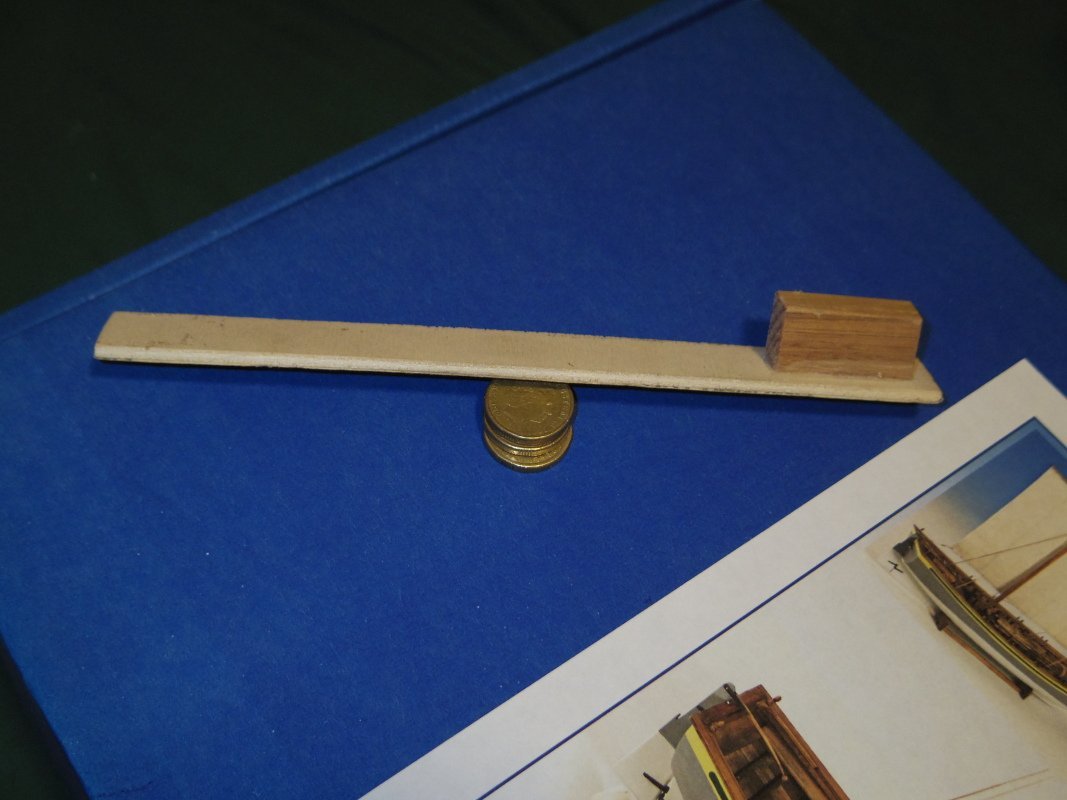
Keep a few cotton buds handy, dampen them with saliva and wipe up the excess. But I don't often need them. Also my sanding stick is a fairly flexible ply about 20 x 180, it spans a few frames and follows the curve.
-
I glue the plank edges. I do it full length using a syringe but even a few spots would help.
-
I don't think I'd bother.
-
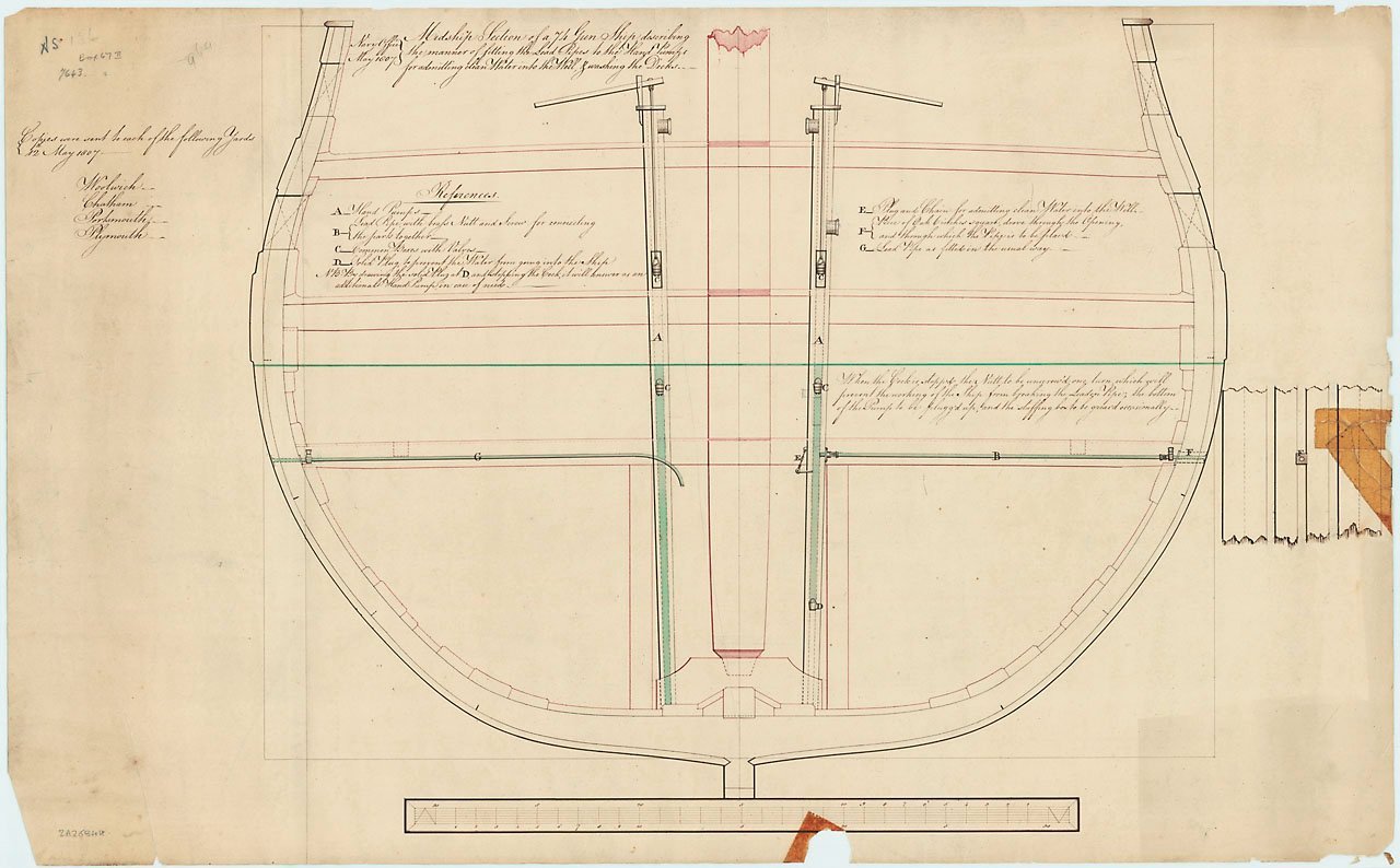
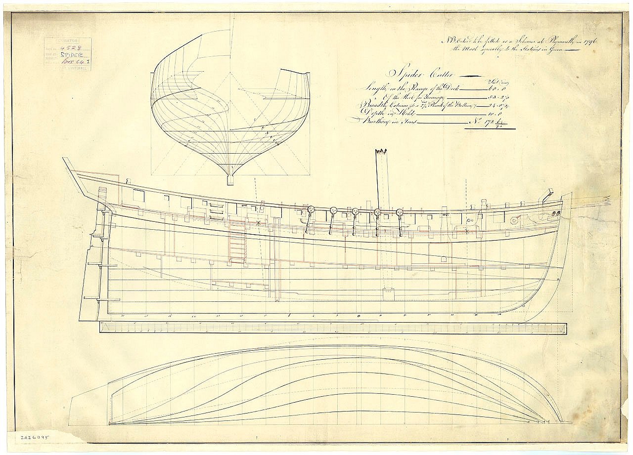
6844 https://www.rmg.co.uk/collections/objects/rmgc-object-86635
-
Two examples, On the left 1 tap at the hull to let water drain into the well to then be pumped out. On the right 2 taps one at the hull and one at the base of the pump, this allows you to do the same as above or to pump from outboard without filling the well.
-
Wow, that's looking really good Tim. Perhaps a hair (literally) more off the highpoints of strake 5 but that's being pedantic.
-
The concept works, but back to planking for now.
-
Getting there, getting there.
-
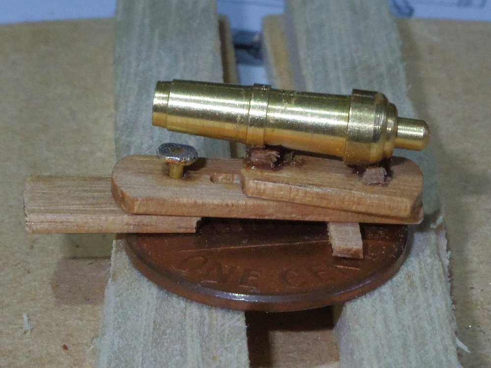
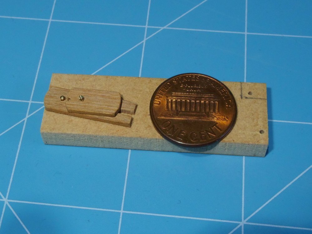
Well, if I can pull this off the guns will have functioning carriages.
-
Just say 'several lifetimes, but it seemed to go faster than that'.
-
Thanks. Lets call it about 18 hours work. But to be fair half of that was letting glue dry.
-
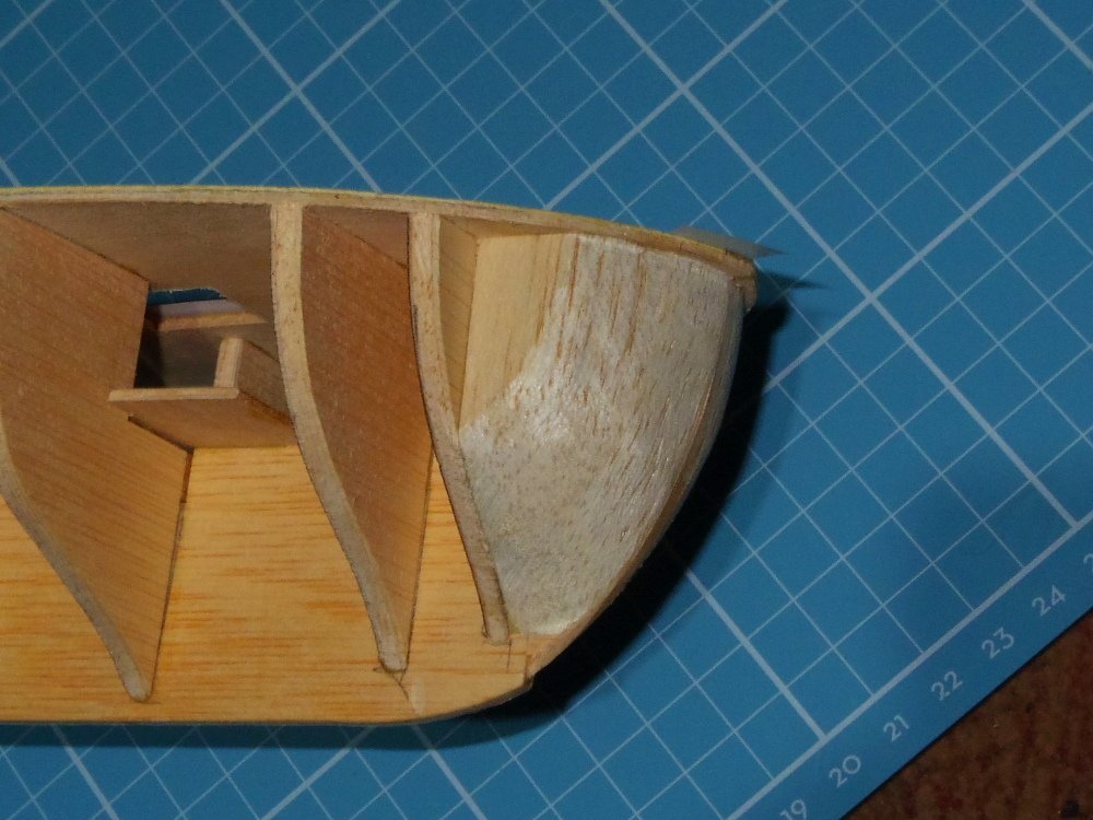
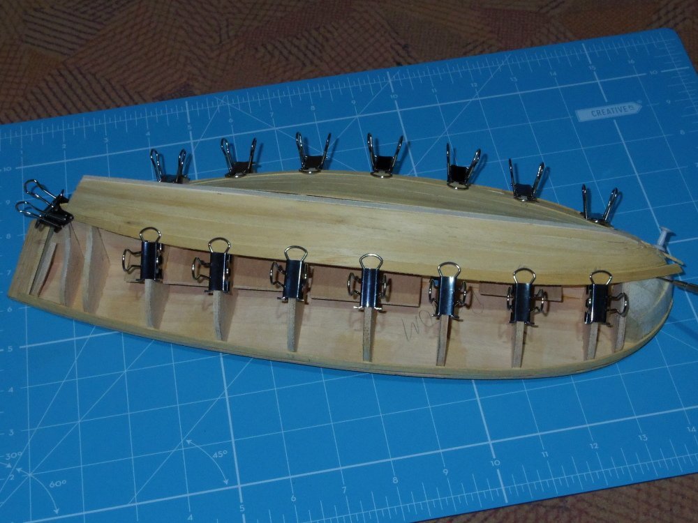
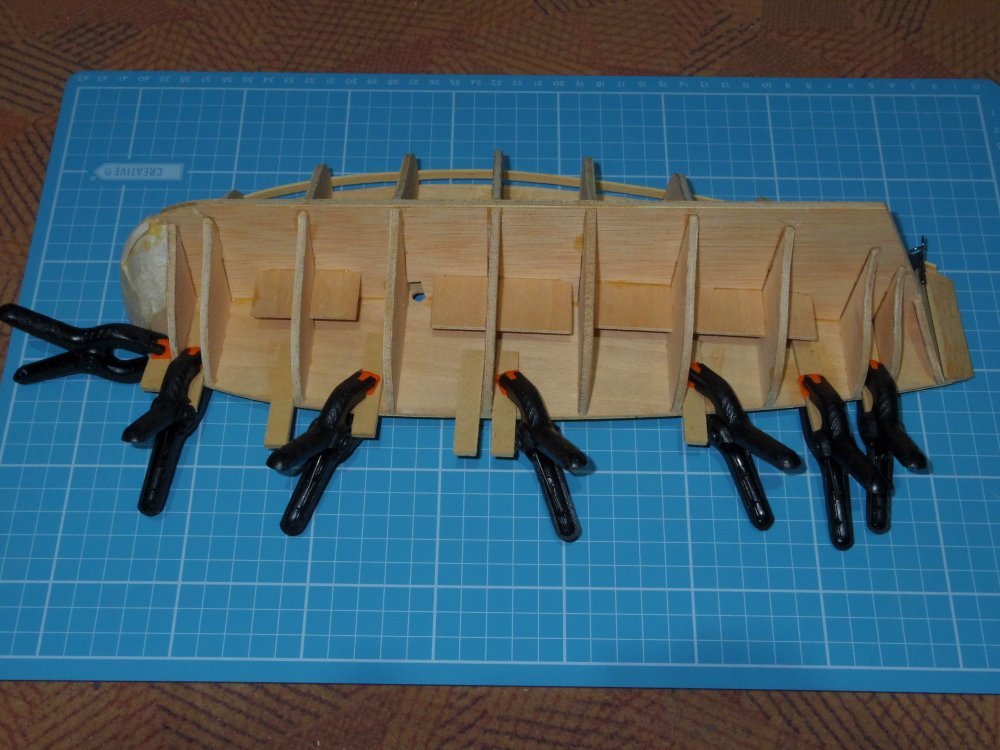
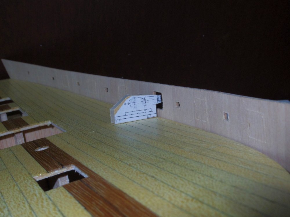
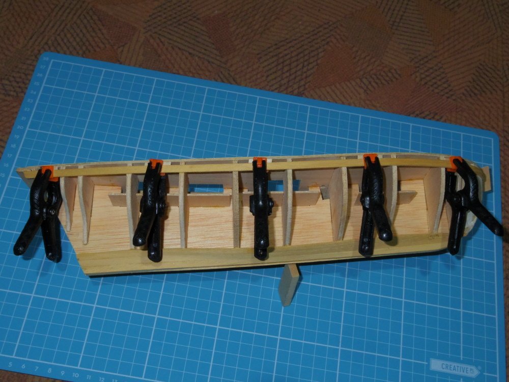
A little progress, seven strakes of the first planking. I added temporary spacers for setting the gap between the deck and the sheer using rubber cement, this sets the position of the bulwarks. Holding the bulwarks in position proved difficult and there was nowhere to clamp them so I added tabs inside the sheer strakes. That worked well but means I will be fitting the bulwarks before I finish the first layer of planking. I also looked at doing a 'proper' carriage for the guns. It's still a little too tall.
-
Not really, on my launch I used shellac and a cheap (stiffish) artists paintbrush. One coat and only enough brushwork to make sure I didn't miss anywhere and that it wasn't too thick (no pooling). Really quick and it looks like bare wood. See posts 65 & 66.
-
You've done such a lovely job, it's a real pity about the beech. I think you need to seal the inside to help stabilise the wood though.
-
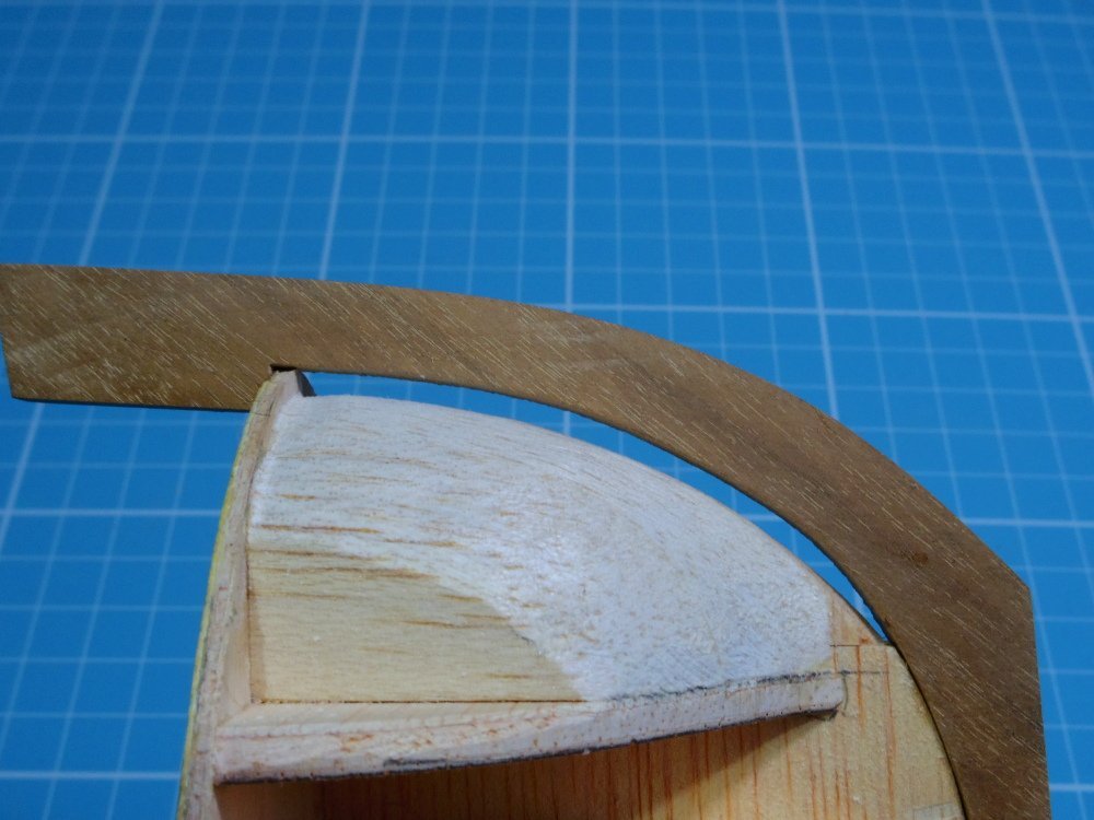
The reasons are complicated but it boils down to 'I have to move the stem forward by this much': For those complicated reasons mentioned above, I thought (incorrectly) that it should touch the deck as in the pic in post #22. (Note: balsa has already been added to fill out to the end of the deck compared to the pic in post #22.)
-
That was and still is the plan, the stem will just be further forward than I had pictured in my mind but where it is supposed to go.
-
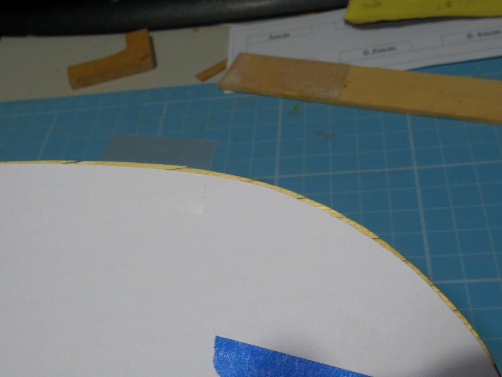
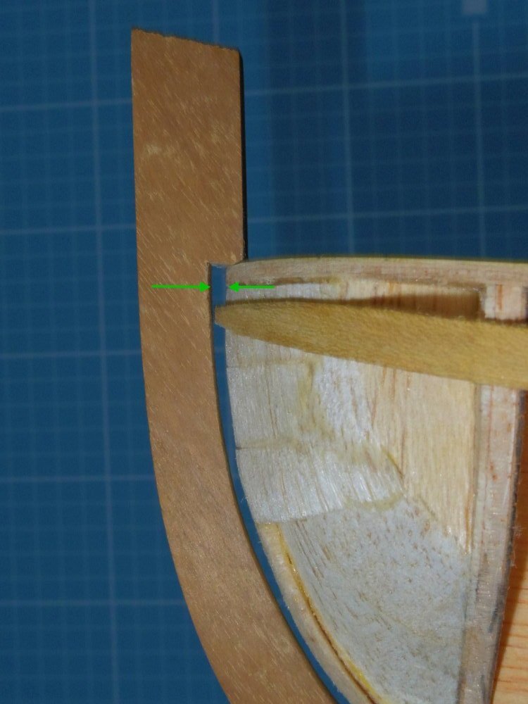
Ok, I made a boo-boo. When making my balsa bow filler I assumed that the planking finished inside the stem (which it does) but I forgot, didn't understand that the stem is intended to be fitted after the planking is finished. As a result I made the filler to accommodate the planking allowing it to fit inside where I thought the stem should be but the stem is actually going to be about 2.5 mm further forward. (don't worry, the picture will help). This is with the stem in the position I thought it should be: What I now have to do is fill this gap, later the stem will be fitted the same distance further forwards.
-
Looking it seems 'just below the gun ports' might be the standard. Ultimately a painting is just a data point, now if you could come up with a photograph... 😁
-
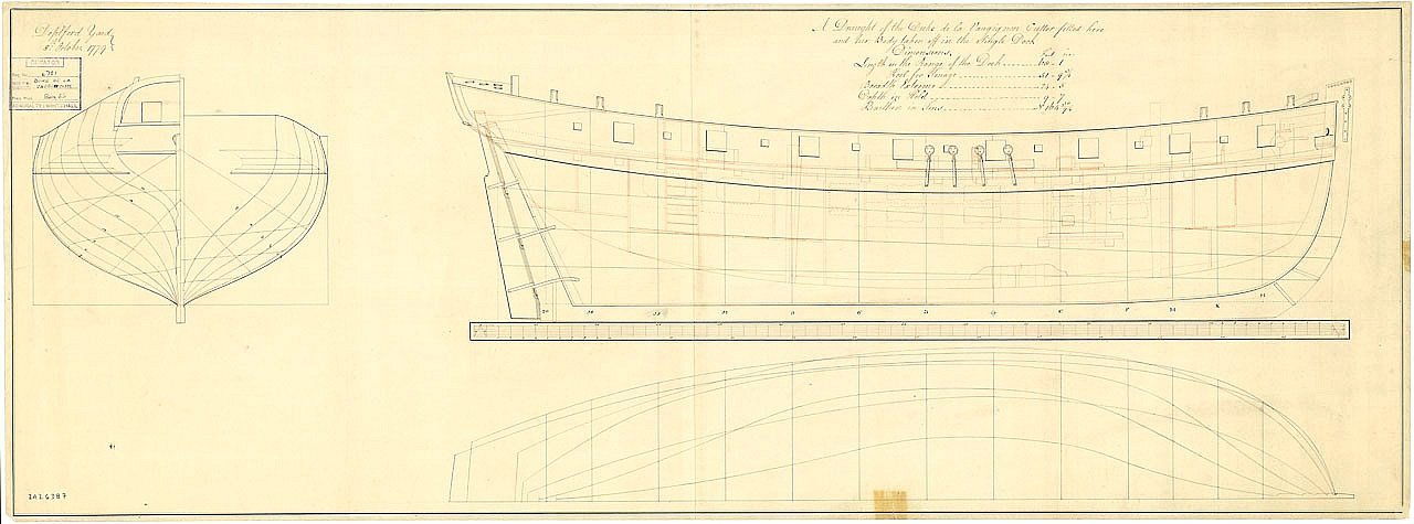
More worms. These are two captured French cutters (late 1700s) Two other drawings I have show just above and just below the deck. So far only American drawings show near the top of the bulwarks. But..........
-
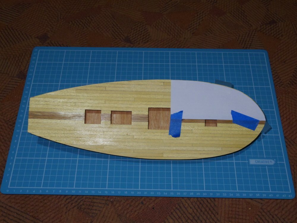
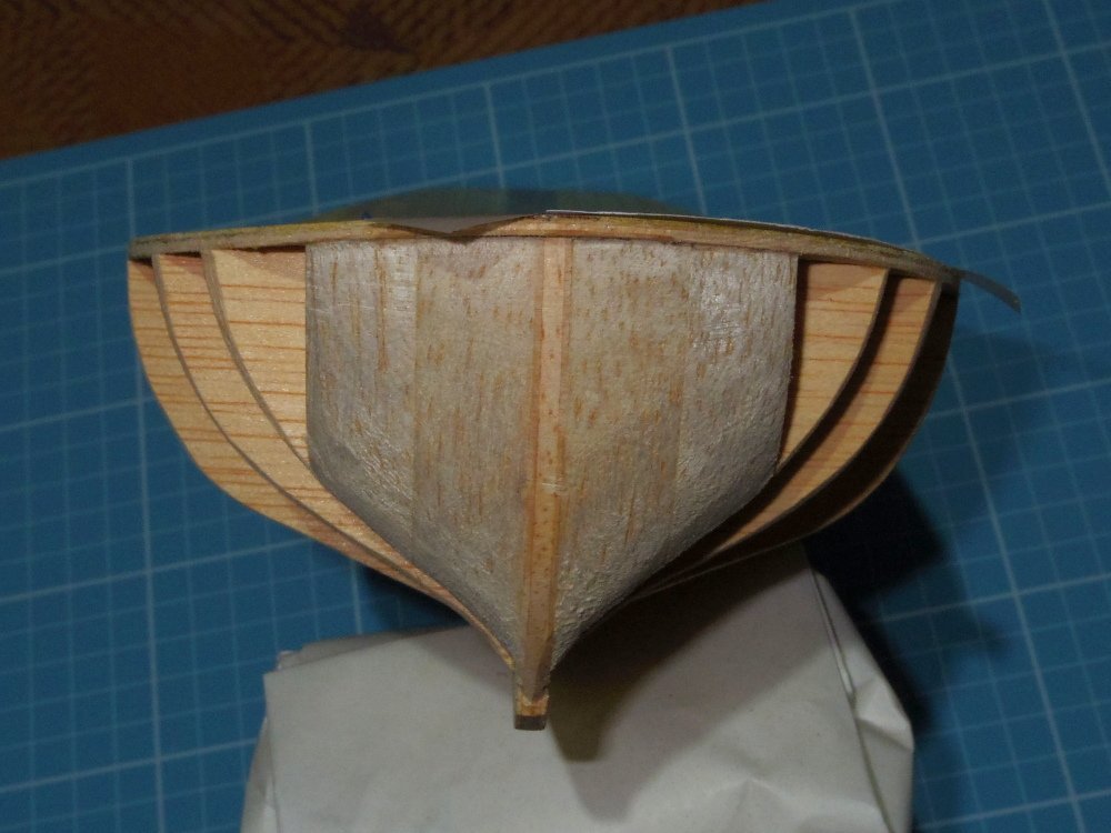
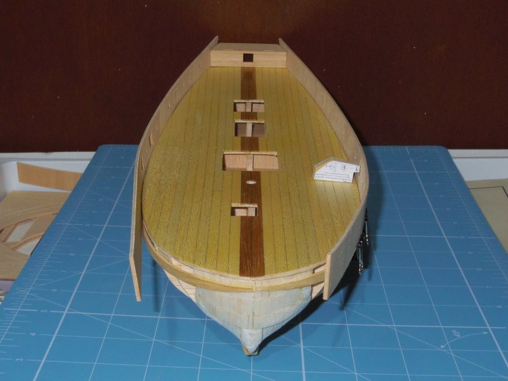
Ok, deck planked. That took longer than I expected. It showed up some asymmetry forward: And some shots of the new bow fillers: