


iMustBeCrazy
-
Posts
976 -
Joined
-
Last visited
Content Type
Profiles
Forums
Gallery
Events
Everything posted by iMustBeCrazy
-
 Umm. Earlier was 2018, before I found this forum. First ever 'build' and I wasn't happy with what I was doing and with the family connection I wanted to show more of the interior. The moulds/bulkheads were corrected. Which lead to something more like Bruce is suggesting: But I still wasn't happy, so I bought a Bounty Launch kit and found this forum and started learning. But I still wasn't happy, so I designed and built my small Cutter and learned a lot. I was quite happy with that so I designed and am building my Bounty Launch (and 'Kitty'). Which brings us up to date.
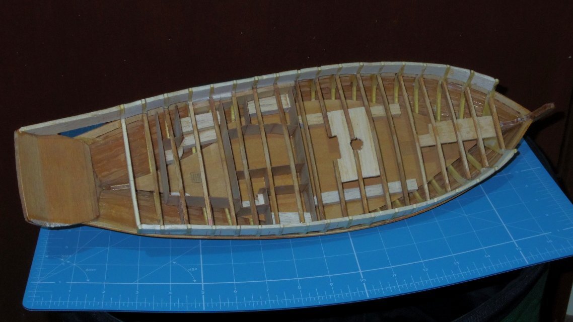
-
Here's one I made earlier
-
True, but the plans Tim has will build him a cutter, just not Speedy. For me, my great grandfather sailed out here on Lapwing so I'm more inclined to build her and get her right, unfortunately.
-
Definitely a nightmare. 2 sets of plans, 2 draftsmen. Sheet 1 and 2 are a pair but the one showing the moulds is different. The book of building the model gives the answer, despite the name on the box and book It's not Speedy! Page 31 of the book gives references and says "The original Admiralty draught of the naval cutter that the 'Speedy' model was based on" and shows a drawing. Except it's not! The drawing shown is ZAZ6373 which is the drawing 'Skylark' was to be built from along with 'Swift', 'Bramble' and 'Diligence'. I believe these were cancelled and the names 'Skylark', 'Swift', 'Bramble' and 'Diligence' and 'Speedy' were later given to vessels built on the lines of the 'Lapwing', hence the confusion. So the model is of the proposed 'Skylark' perhaps with some alterations taken from 'Lapwing/Speedy' drawings. Lots of room for confusion. So I confess I was wrong, it's ZAZ6425 which is Lapwing and therefore Speedy.. Tooooo many drawings.
-
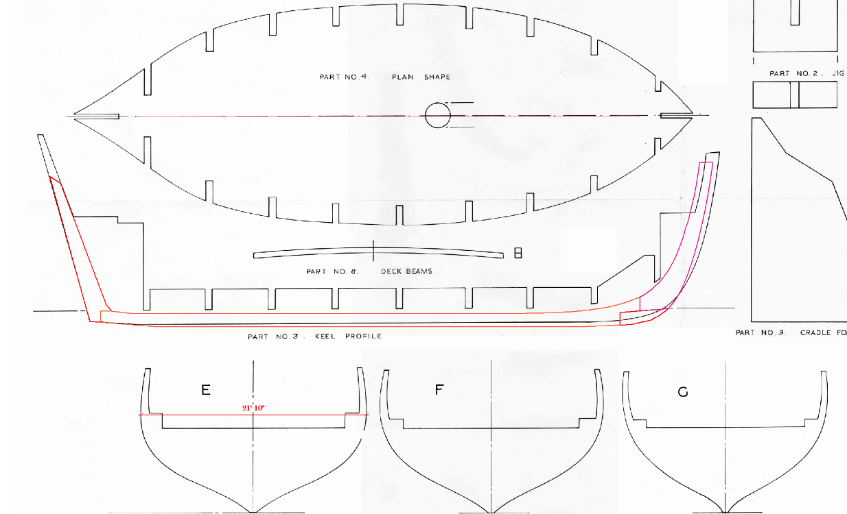
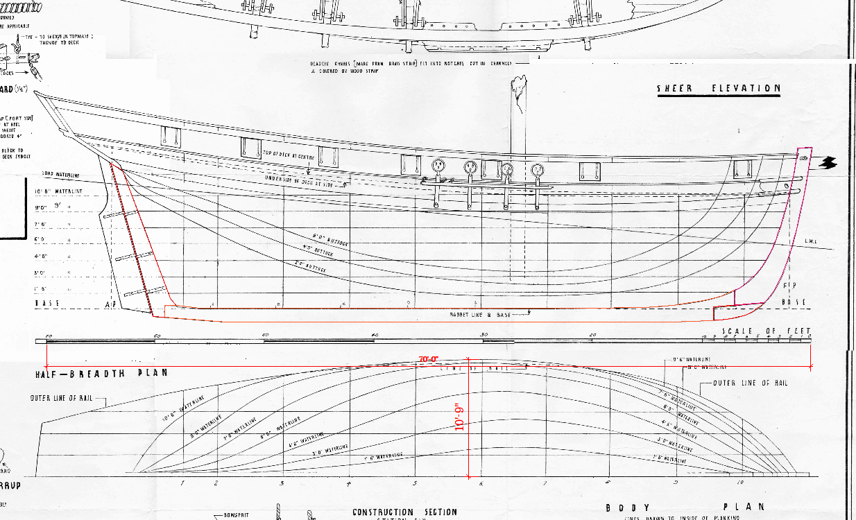
Are you sure? I've been asleep but looking this morning there are some discrepancies between drawings. And it doesn't help that there are 10 stations and 9 moulds. The 1st drawing below has a scale to which I have corrected but the aspect ratio is wrong (only just noticed that) station 6 should be 10'11" ( half of 21'10" ). I traced the sternpost, keel and stem and copied it to the other drawing which has been scaled to Mould 'E' which should be 21'10" (twice station 6) and the length doesn't match. So there is possibly something wrong with the scaling of individual sections. Maybe? Or maybe I'm still asleep having a nightmare? See post #7.
-
At this stage she's looking better than the original! But don't forget the new paint scheme:
-
Sorry Tim, Speedy (1928) is based on Lapwing (1916) and believe me, there are no hires plans. Edit: I forgot about the Danish drawings found by Bruce_d (post #11 below) Revisit my Lapwing thread for clues: https://modelshipworld.com/topic/23486-lapwing-1816-revenue-cutter/
-
Allan, I think the context is 'not reclaimed/recycled" so ground as in the past tense of grind. toes, tocs, I don't know.
-
The Captains (armoured) observatory. It's a little more complicated (just a little I promise). But perhaps I'm being fussy. And no, I wouldn't be making the boats either. Way over the top.
-
Tinting shellac?
iMustBeCrazy replied to CPDDET's topic in Painting, finishing and weathering products and techniques
One thing to be aware of is how much shine you want, one coat of shellac can give you a low sheen finish but if you keep adding layers to get a darker colour it's going to get very shiny. So a few different diluted stains and tinted shellacs will give you the best control. Edit: Bob's got it, listen to him. -
Tinting shellac?
iMustBeCrazy replied to CPDDET's topic in Painting, finishing and weathering products and techniques
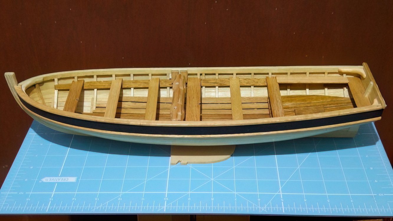
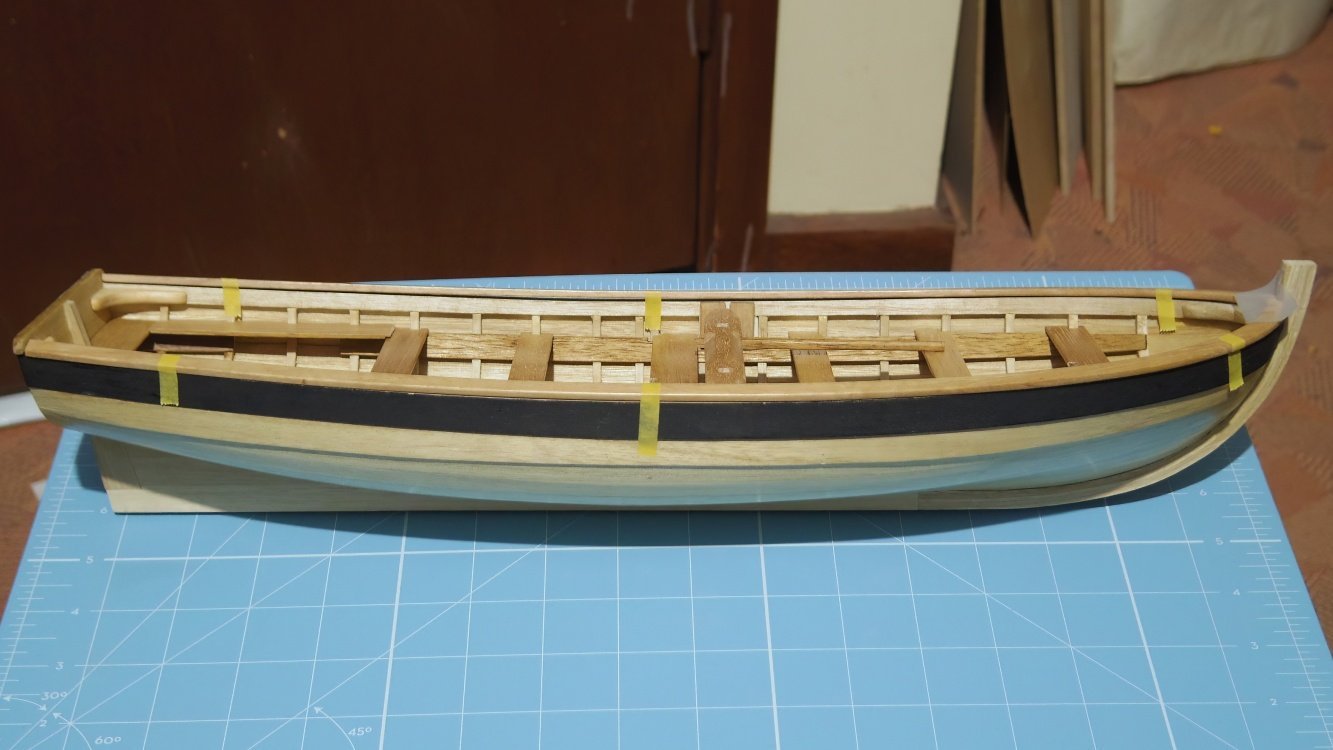
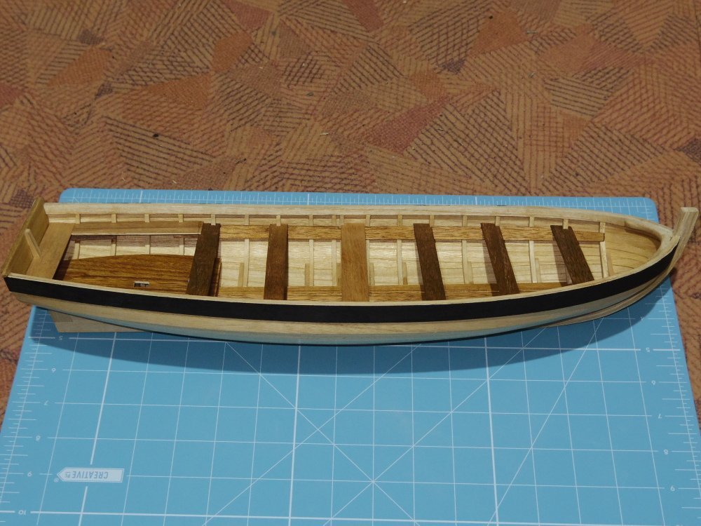
I've done a little Dave, using spirit based stains (dyes,tints). I've also used the stain on it's own but diluted with denatured alcohol. There are only two three types of wood in my Bounty Launch, the knees are basswood, the thwarts footwaleing cap rails and windlass are Tasmanian Oak and the rest (including the quarterdeck) is Paulownia: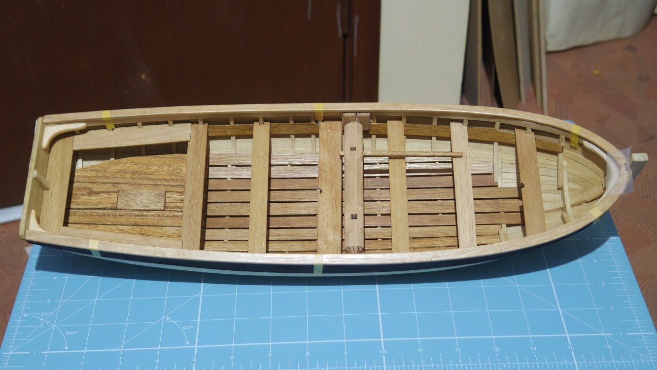
-
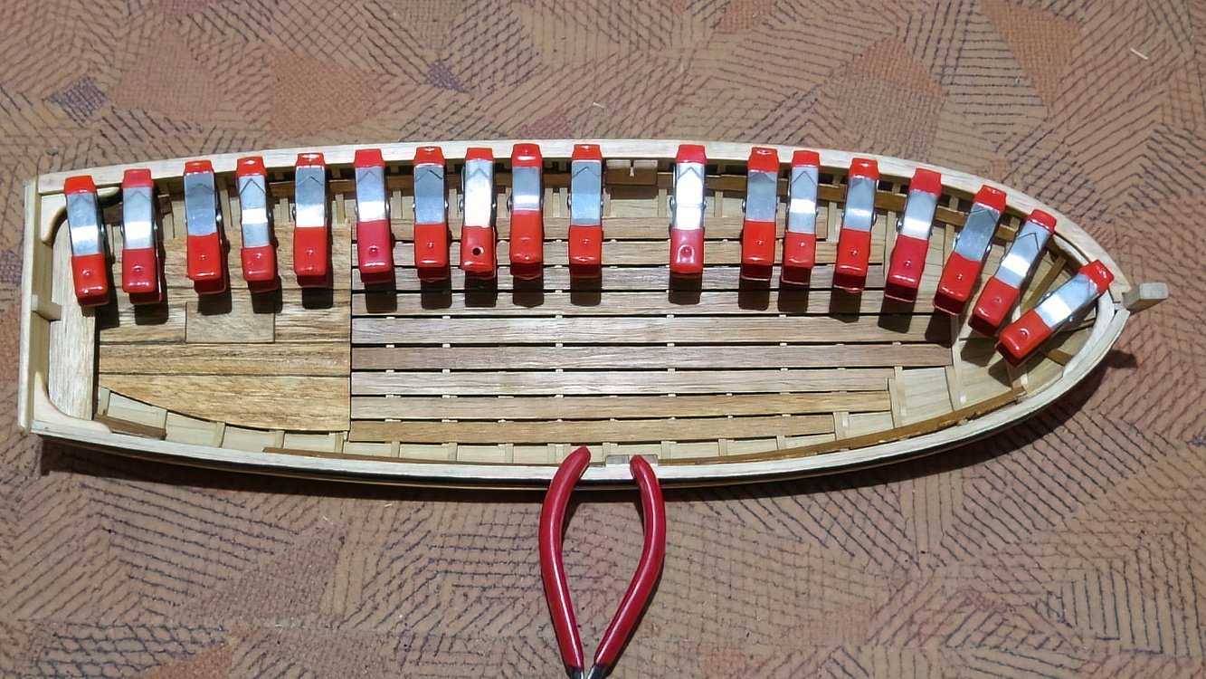
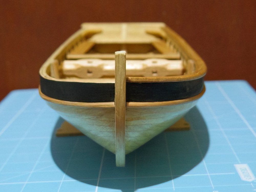
Fenders and port cap rail fitted. I need to finish the interior before fitting the starboard.
-
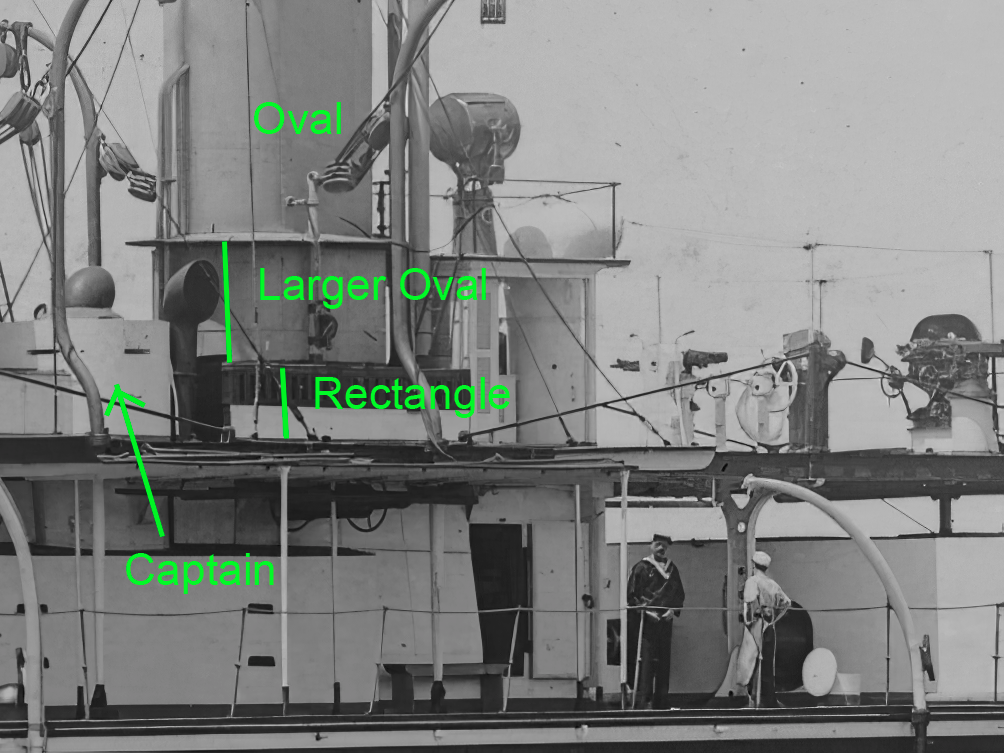
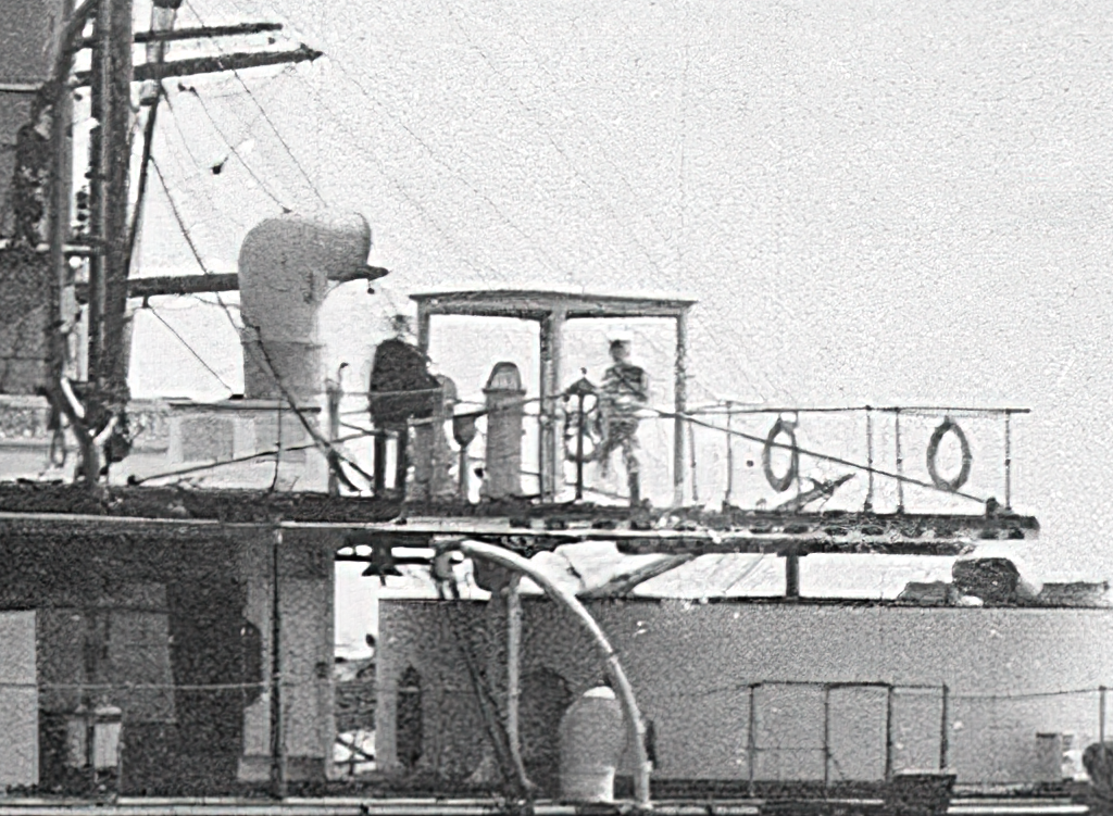
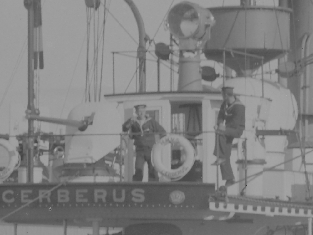
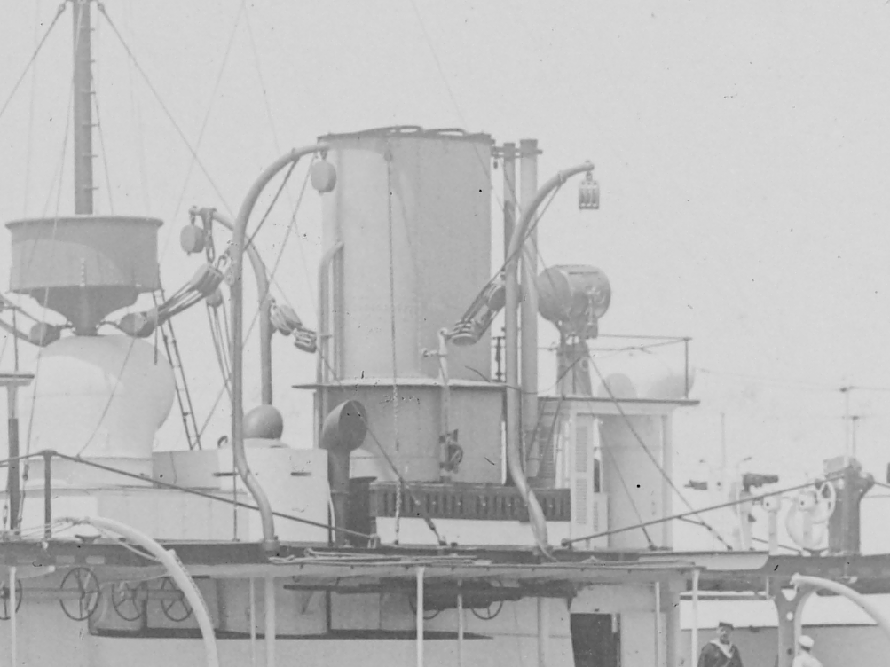
Possibly the same thing that keeps moving? The wheelhouse is actually the binnacle-house (9). With the wheel at (19). The binnacle-house becomes the binnacle-pergola. A new compensated* waterproof binnacle is installed and the pergola is moved to between the funnel and ventilator. * probably to allow the fitting of the two Nordenfelt machine guns.
c.png.36c36fb6f539e411baa9bdbaa7688162.png)
-
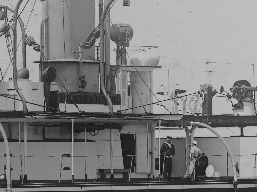
I would say so. I think it's a binnacle. It seems to have 'balls'. Skip it, it only occurs in that pic. It looks like it belongs on a castle wall with a fire in it. You have to strike a balance, it only has to be good enough to sell and price will most likely be the deciding factor. It can also look a bit rustic. Rails could be bicycle spoke posts with automotive electrical wire with the insulation stripped off soldered to the posts (use one that has tin plated wire not bare copper) as cable. Don't do all the railing, just some. Pic 4 zoomed out a bit:
-
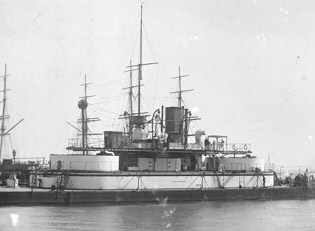
She did when she arrived, later they moved it down the back yard as a garden shed and built a pergola for the helm. Later again they put a search light on the roof of the garden shed. One giant one aft with two small between it and the funnel and one big one forward (I can't see any others but). On the colour plans The giant one aft didn't have the 'hockey-stick' bend.
-
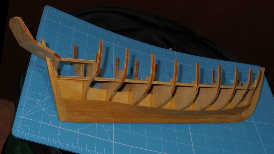
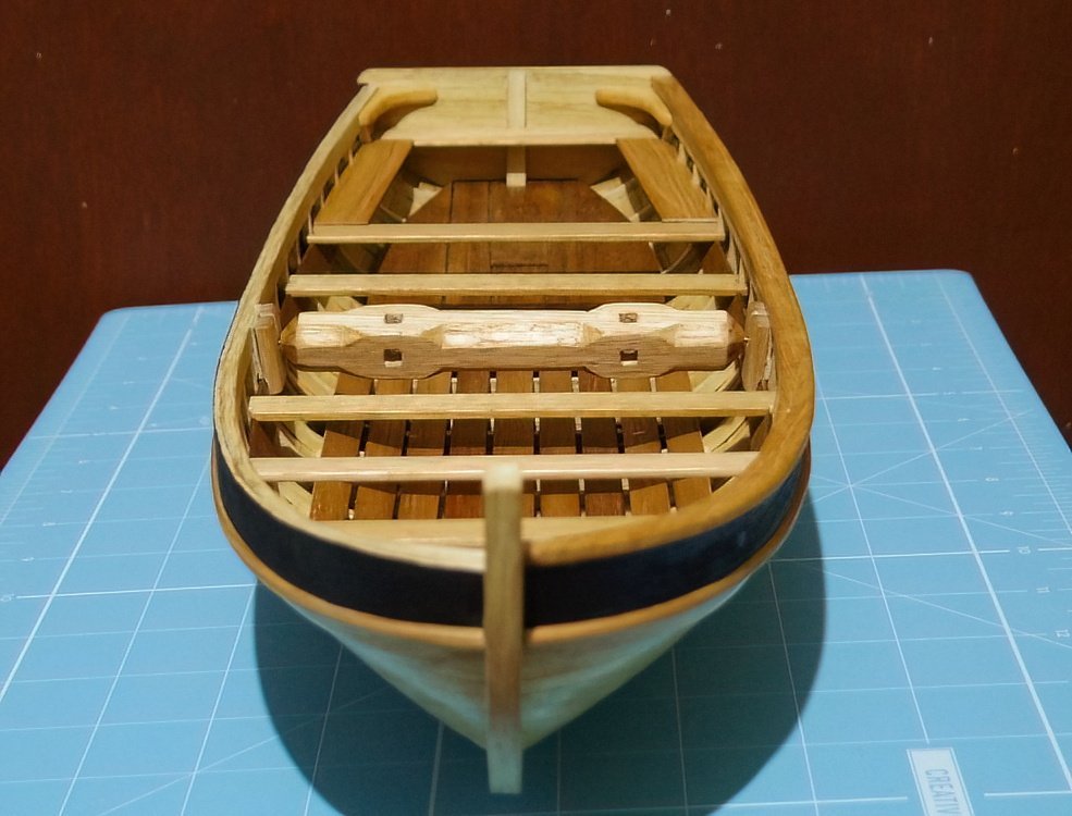
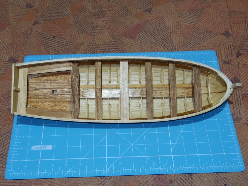
Update time. Transom knees fitted, floorboards fitted, windlass chocks fitted, cap rails and thwarts made, windlass made. To do: Foredeck, there are several valid options but I think I'll go with framed with longitudinal planking. Thwart knees, iron or wood? Both the Bountys launch and large cutter had removable knees (and bolts), the cutters knees were stored in a carpenters chest - wooden knees would take up too much space so they were almost certainly iron - but the launch? Fender below the sheer strake. Cant frame in the bows. Mast steps and brackets, round or square lower mast? The drawings usually show round, the models square. Masts and sails. Oars. Rudder. Other stuff, probably.
-
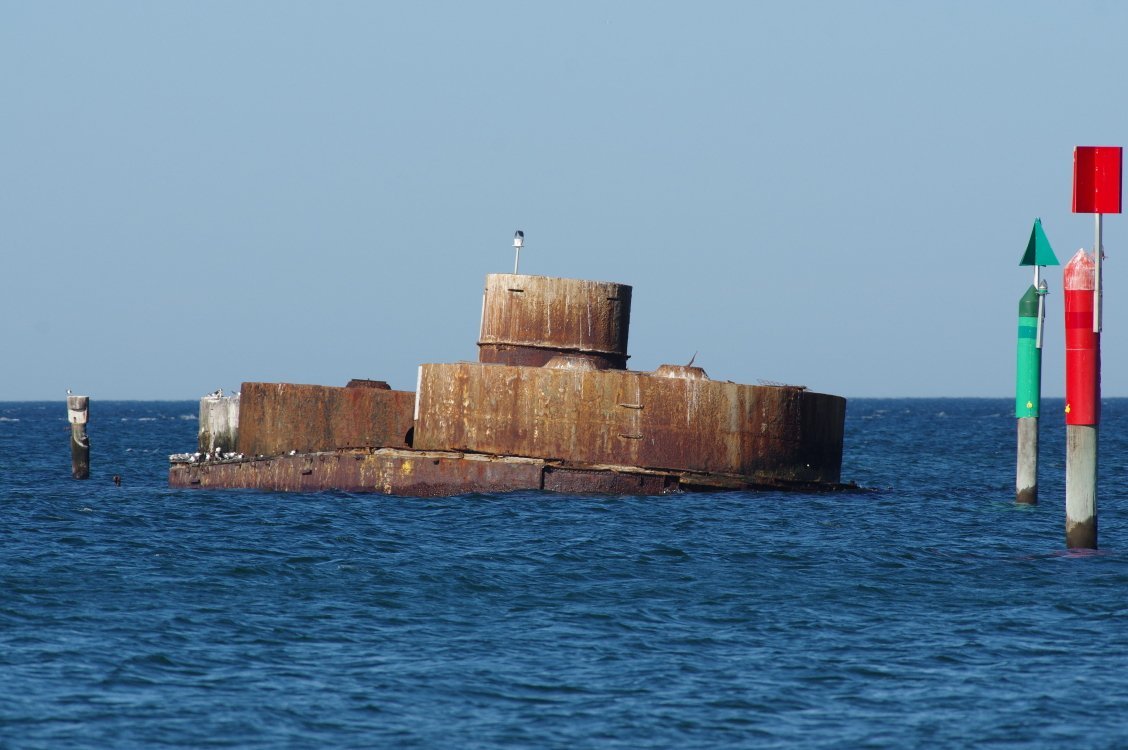
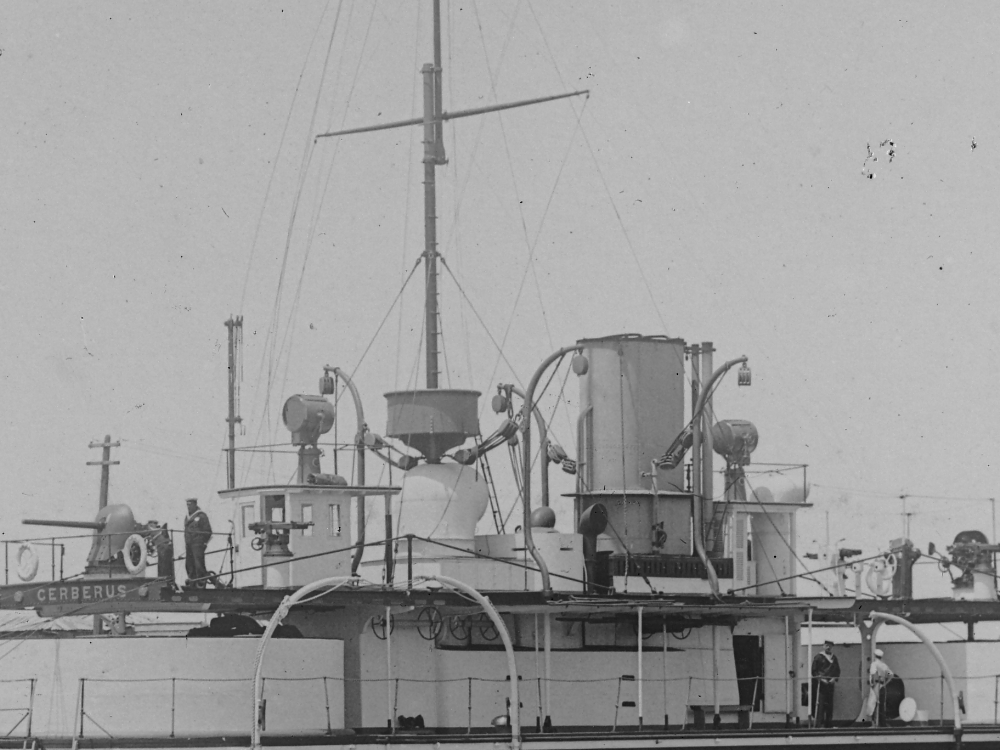
I figured that. One thing they couldn't stop themselves doing was playing with her, hardly any two photos are the same. The deck had a support in the middle of the turret (it shows in the drawing) and the 'cantilevered' deck stopped just past that. True but otherwise she would have been scrapped, at least we can still see her.
-
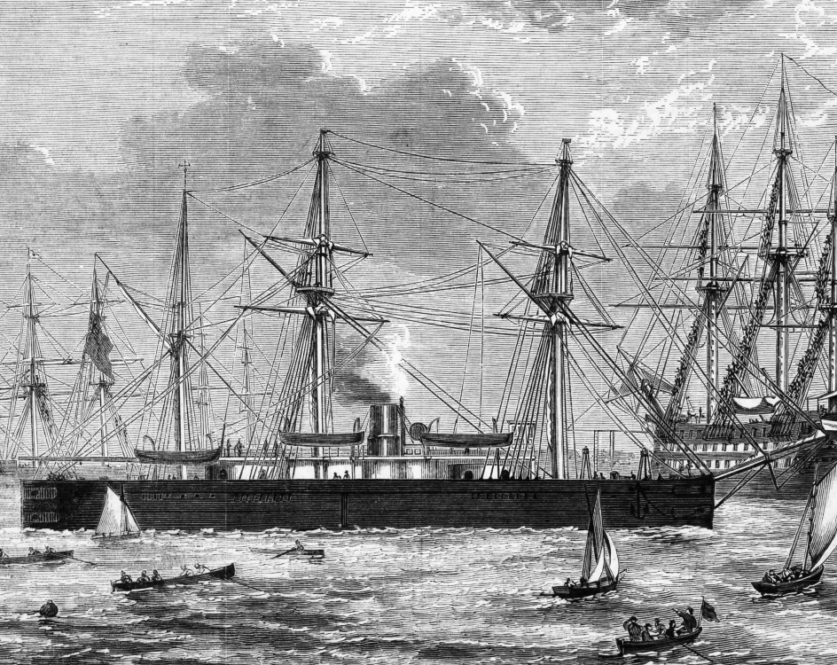
G'day Steven, Having known her all my life and having walked her decks a few times Cerberus is certainly on my list. I have an original of this drawing inherited from my Uncle. I intend to redraw it in CAD but as usual it doesn't quite agree with other drawings I have found, unfortunately I can't find any 'official' drawings. Even her length varies. Anyway, I have a little collection of photos, drawings etc. If you need anything just ask.
-
Transom Build Plans
iMustBeCrazy replied to Matrim's topic in CAD and 3D Modelling/Drafting Plans with Software
Oops. Doh! I blame working in 3D, it's unnatural. But on the bright side, we're getting closer and I'm learning things. -
Transom Build Plans
iMustBeCrazy replied to Matrim's topic in CAD and 3D Modelling/Drafting Plans with Software
Did anybody notice Transom 6 hiding in there? Edit: added Transom 6 and Station 29.5.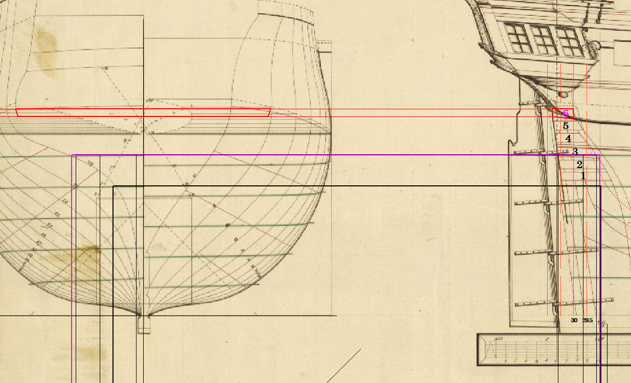
-
Transom Build Plans
iMustBeCrazy replied to Matrim's topic in CAD and 3D Modelling/Drafting Plans with Software
A section of an inverted cone sounds like a pretty good description, but shouldn't there be some curvature to it? Perhaps a section of an inverted bullet shape? -
Transom Build Plans
iMustBeCrazy replied to Matrim's topic in CAD and 3D Modelling/Drafting Plans with Software
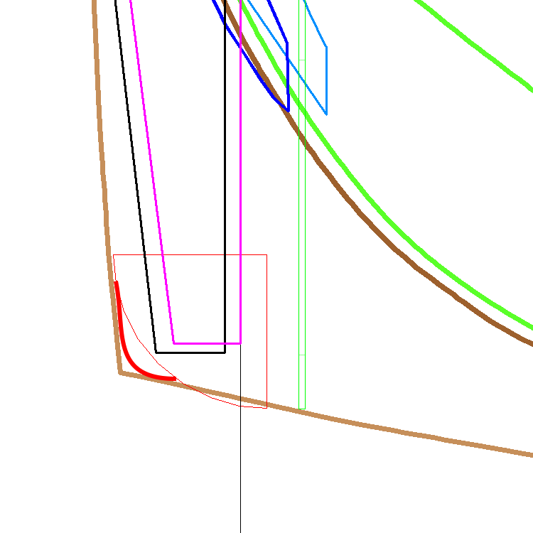
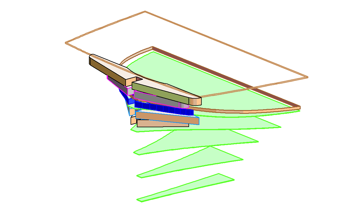
I'm going to have to call it a 'rounded corner', an eighth of a sphere isn't right (but that's what is shown here). However you can see where the rounded corner cuts into T4 and T5, they will have to be shaped to fit. The rounded corner will need to follow the curve of station 29 and transom 3 will need to be extended outside the lower deck. The rounded corner will have to have a tighter radius.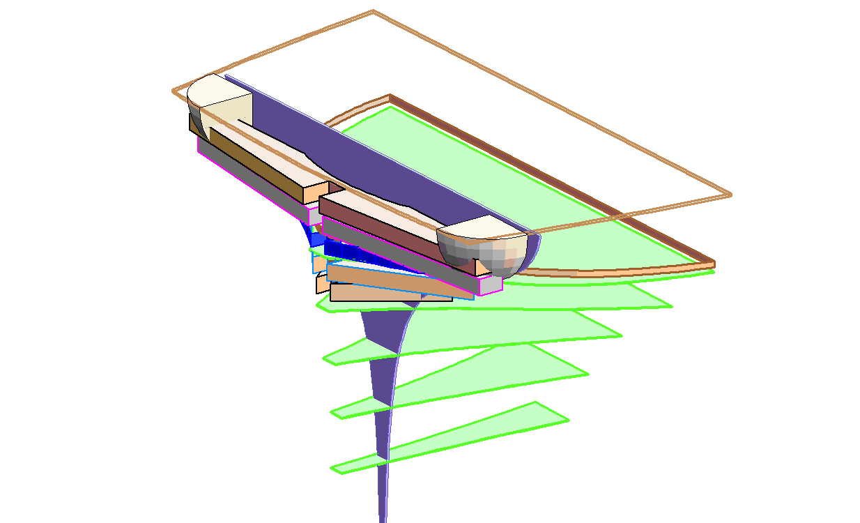
-
Transom Build Plans
iMustBeCrazy replied to Matrim's topic in CAD and 3D Modelling/Drafting Plans with Software
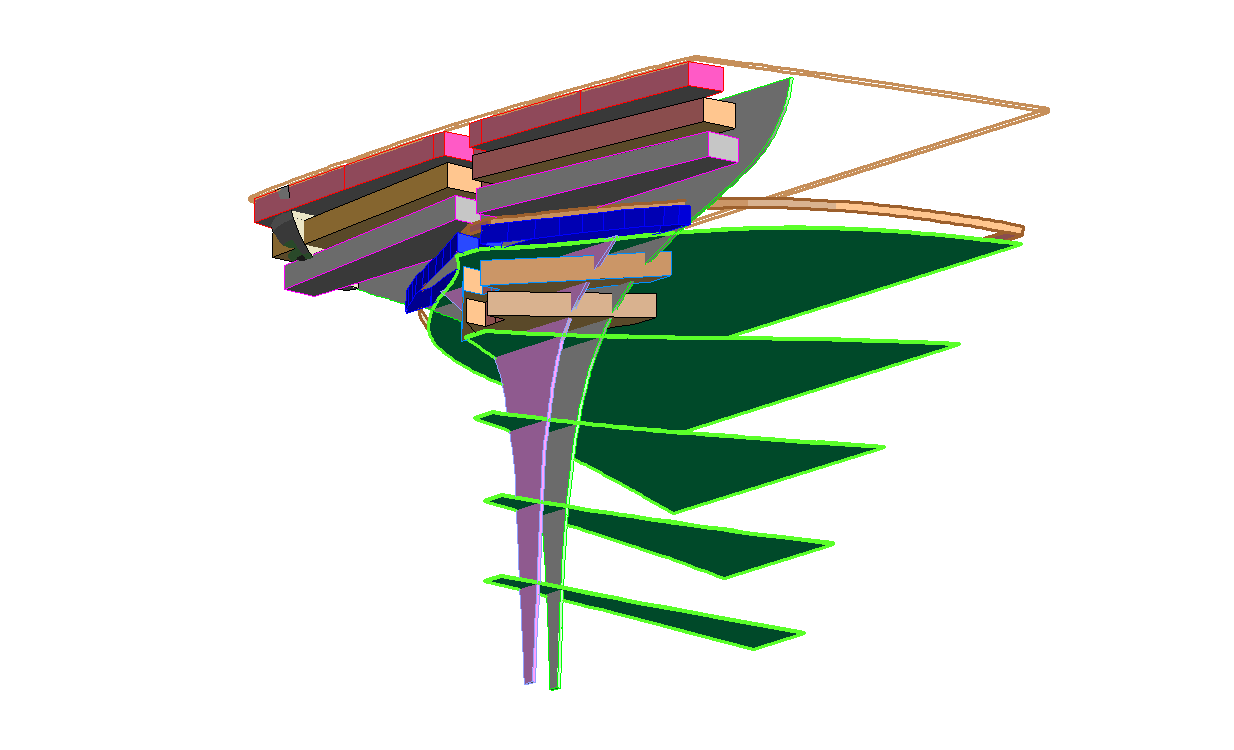
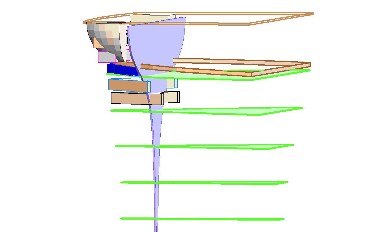
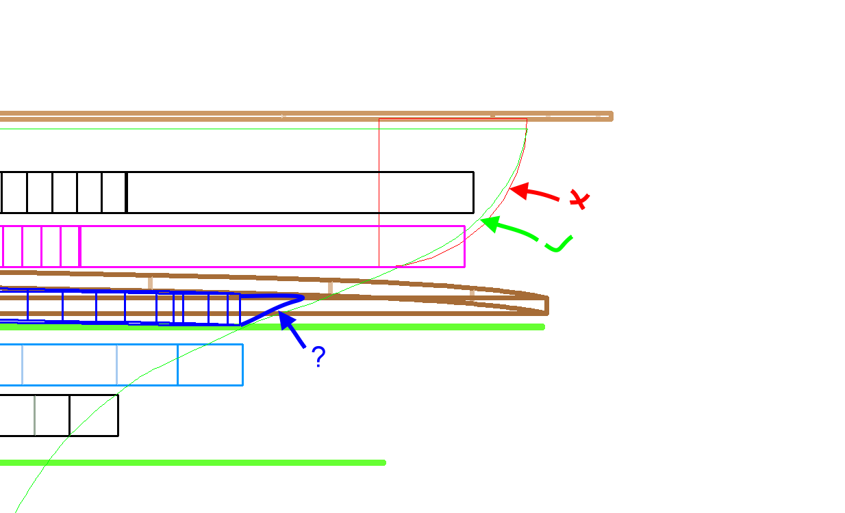
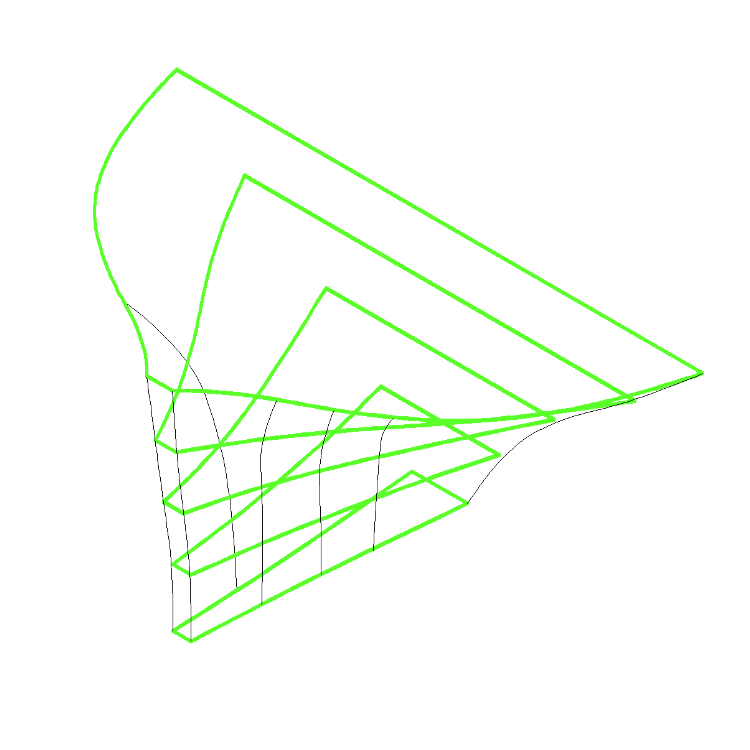
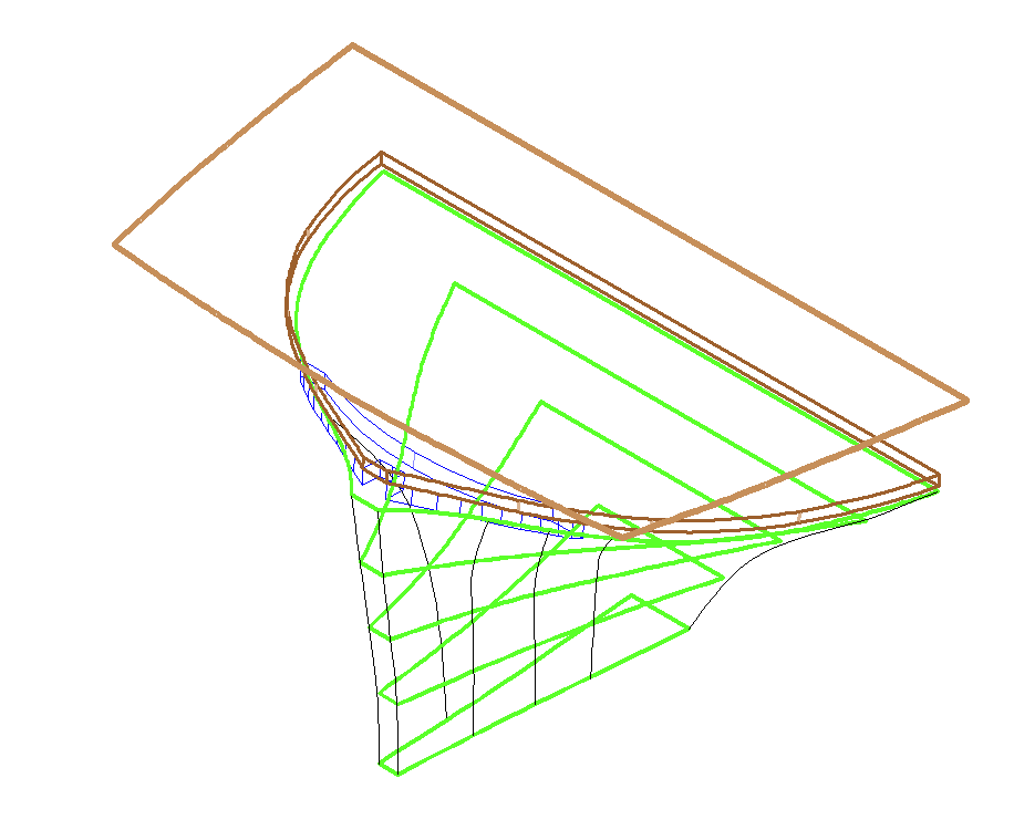
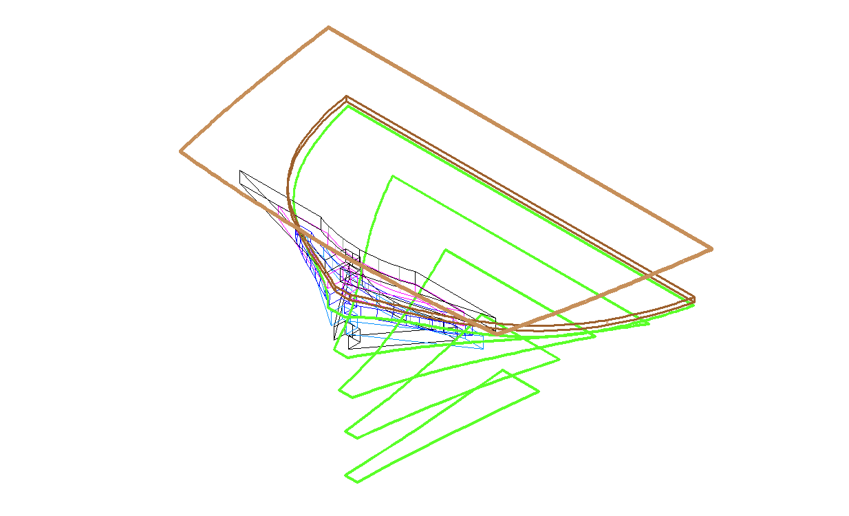
(Note: The drawings below are really rough) It's both to give an intersecting point in space. The problem is that we know there are complex curves above waterline 5 and aft of station 29 and the plans give us no information about this area. Below W4 things are pretty straightforward because we have the shapes at the waterlines and adding new station lines aft of S29 is pretty much like nailing a batten on. We add in what info we have. And here we run in to my lack of skill, Transom 3 (in blue above) should have another curve on the aft surface curving forwards at the bottom edge. More importantly there is a shape, roughly an eighth of a sphere (visualise an orange cut vertically into four quarters the once horizontally giving eight "triangular" segments) with one of the points touching one of those top aft corners. (or something like that) The plans give no information about this shape or how it fairs into the waterlines etc we do have. Obviously the above drawing has errors, T2 is too wide t4 is too narrow and the curves aren't there.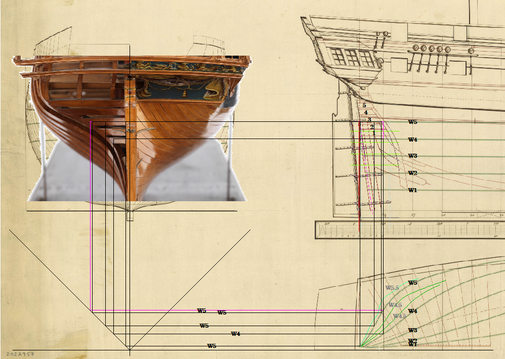
-
Mocking up the interior:
-
From the short grain where those three broke you were always going to have trouble. I suspect they were cut too close to a knot. Bending them at 90° to the way you did may have helped but probably not. If the wood had been milled with straight grain it would be a lot easier. I would suggest boil longer, take a rib direct from the boiling water and clamp it to to the mould near the keel, then walk your fingers along the rib bending it to the mould as you go. If at any time it doesn't feel like it's going to bend throw it back in the boiling water. I broke several when I did it but I salvaged a couple by putting a clamp over the split to keep the bend then superglueing them when they dried.


