stuglo
-
Posts
707 -
Joined
-
Last visited
Content Type
Profiles
Forums
Gallery
Events
Everything posted by stuglo
-
Swan-Class Sloop by Stuglo - FINISHED - 1:48
stuglo replied to stuglo's topic in - Build logs for subjects built 1751 - 1800
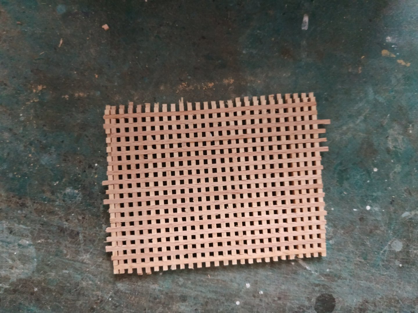
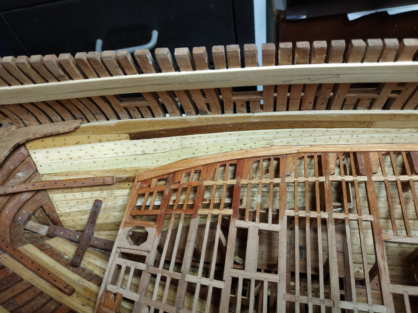
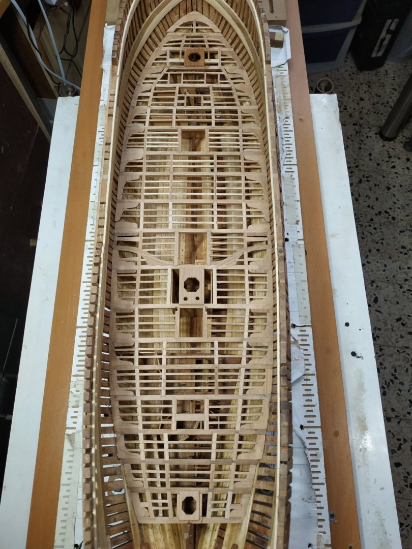
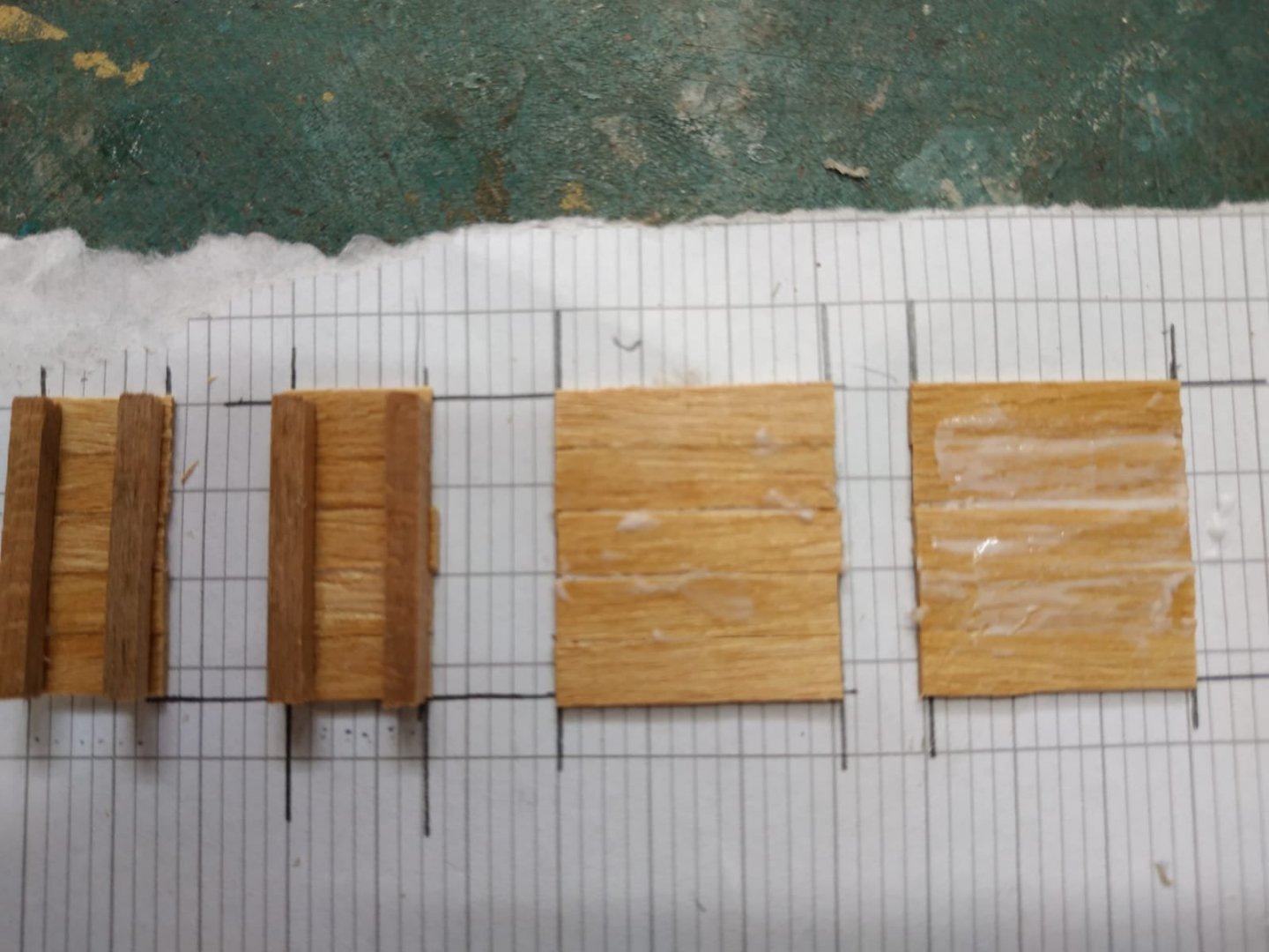
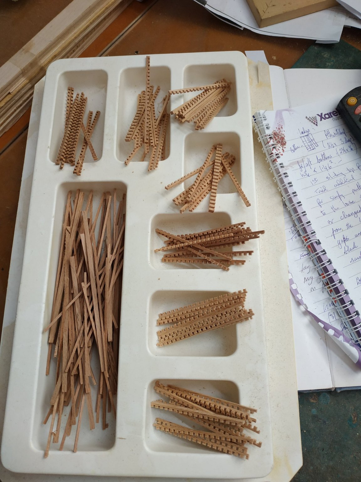
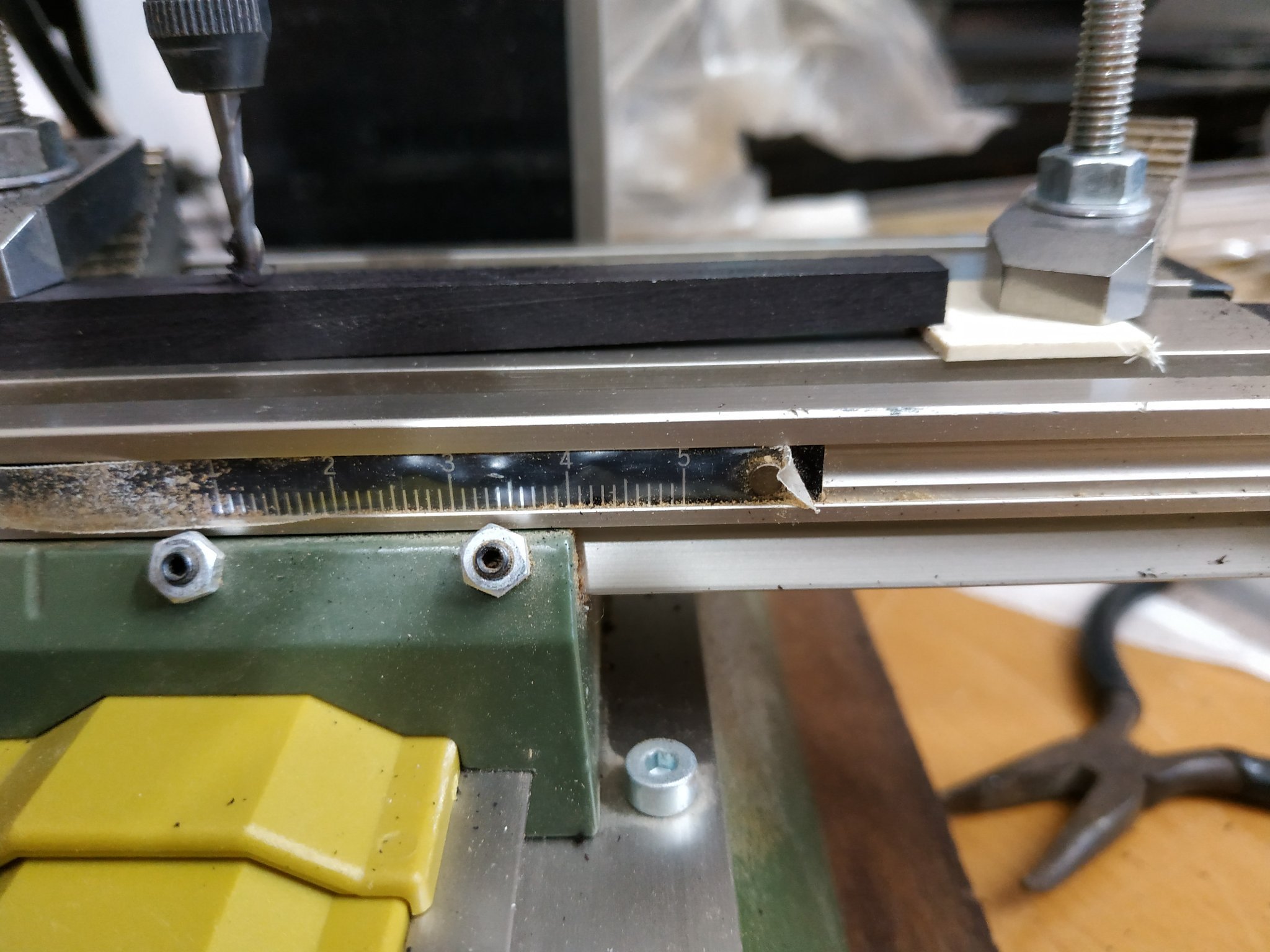
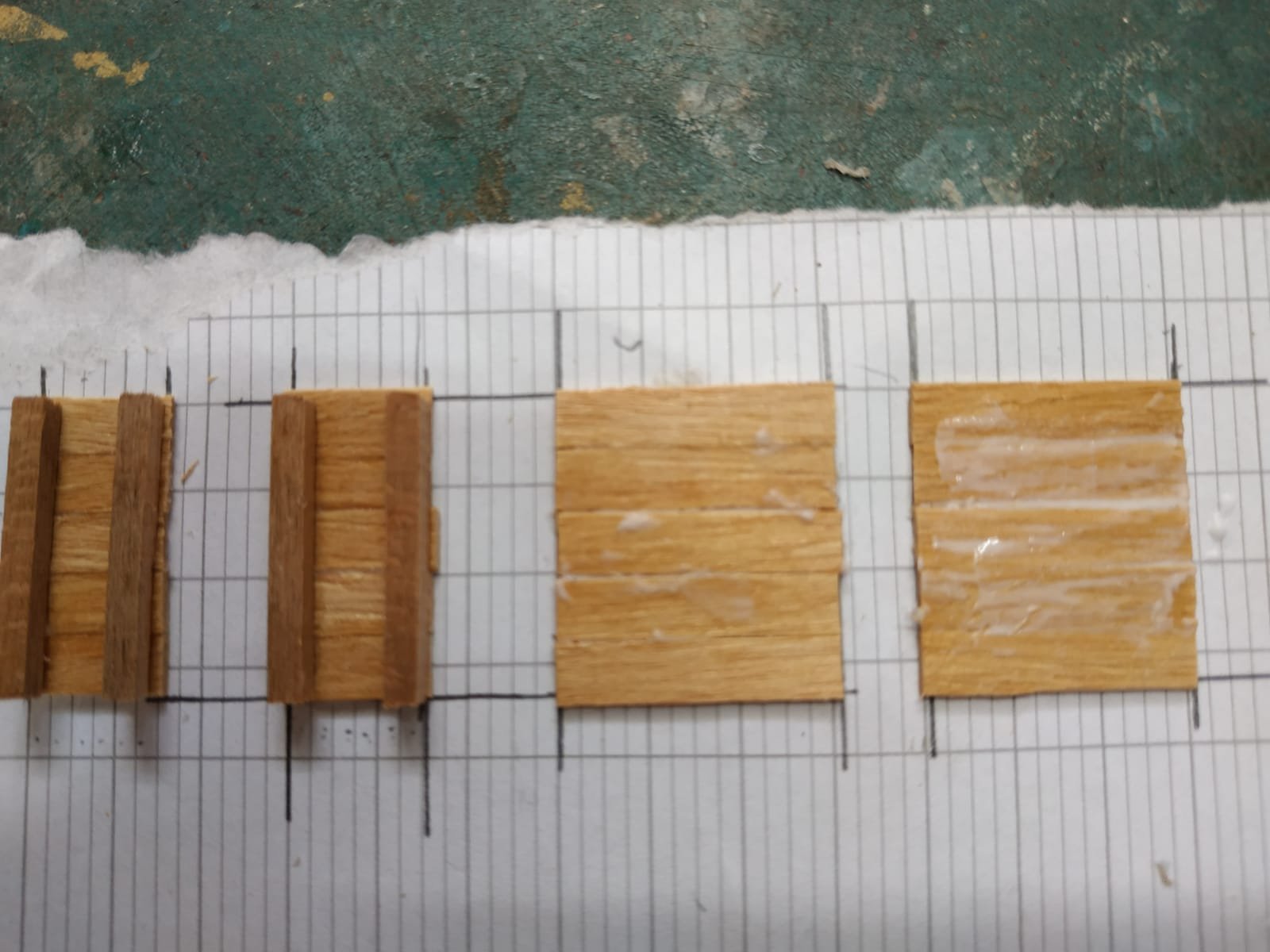
Lower Deck (cont.) Before planking, some structures need to be made. The first are the Gratings. These have always seemed too difficult and in previous scratch builds, have used left-over pieces from various kits and assembled them. I’ve read dozens of explanations which seemed too difficult to build or even understand. Even the TFFM didn't enlighten me. Then I checked out a later video of Kevin Kenny (#79). Genius (someone who simplifies the difficult and/or originates a new method) THANK YOU, SIR. First, make a sliding table (in my case , a ProxxonFET). The gratings consist of : ledges (athwartship)- the notched bits-1.33mmX1.6mm (deep) And for/aft Battens, 1.46mmX0.4mm thick. My saw blade is 1.6mm (very convenient). A stop/fence made from a strip 1.6mmX1.6mm, and glued at a distance that a cut strip will be 1.6mm wide, (For now relied directly on sliding table and not an additional jig.) A 3mm thick blank is squared off, and with the grain at RIGHT angles to the blade,which is lowered to allow a 1.6mm groove to be made. Held firmly against the fence, the first cut is made. The blank is then moved so this groove SITS on the fence, and a second groove cut. This in turn sits on the groove and another groove cut etc until all the blank is furrowed. WATCH OUT FOR THE SAW BLADE. (I placed some downward pressure to help form uniform grooves) As I said, sheer Genius. While set up, made enough for later use with the upper deck.(Foredeck more delicate) Put the sliding table aside . These grooved blanks are turned 90deg and 1.6 mm slices cut with the grain I changed the saw blade from the standard 37 teeth ( it damaged a few trial passes) to a 200 tooth blade-not really its purpose, but it was magic) and cut the 1.6mm wide strips ALONG the grain. Battens: My thicknesser can’t make 0.4mm blanks -only 1.3 minimum. Never mind. Cut strips ( ALONG grain) similarly 1.6mm wide The ledges and battens are interlocked and fixed with diluted glue. The holes seem pretty uniform and close enough to the appropriate size. The excessive thickness will be sanded off after each piece is cut to size. Thanks again Kevin.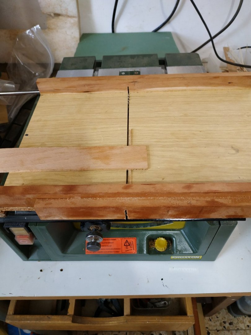


-
Ssshhh- a certain company in SW England is now taking orders. My Bosun is in for a surprise .
-
Swan-Class Sloop by Stuglo - FINISHED - 1:48
stuglo replied to stuglo's topic in - Build logs for subjects built 1751 - 1800
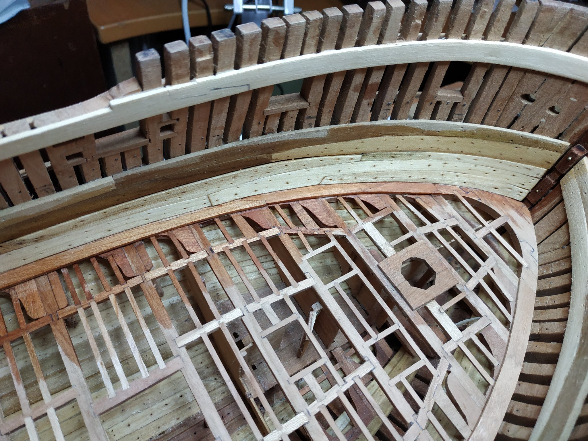
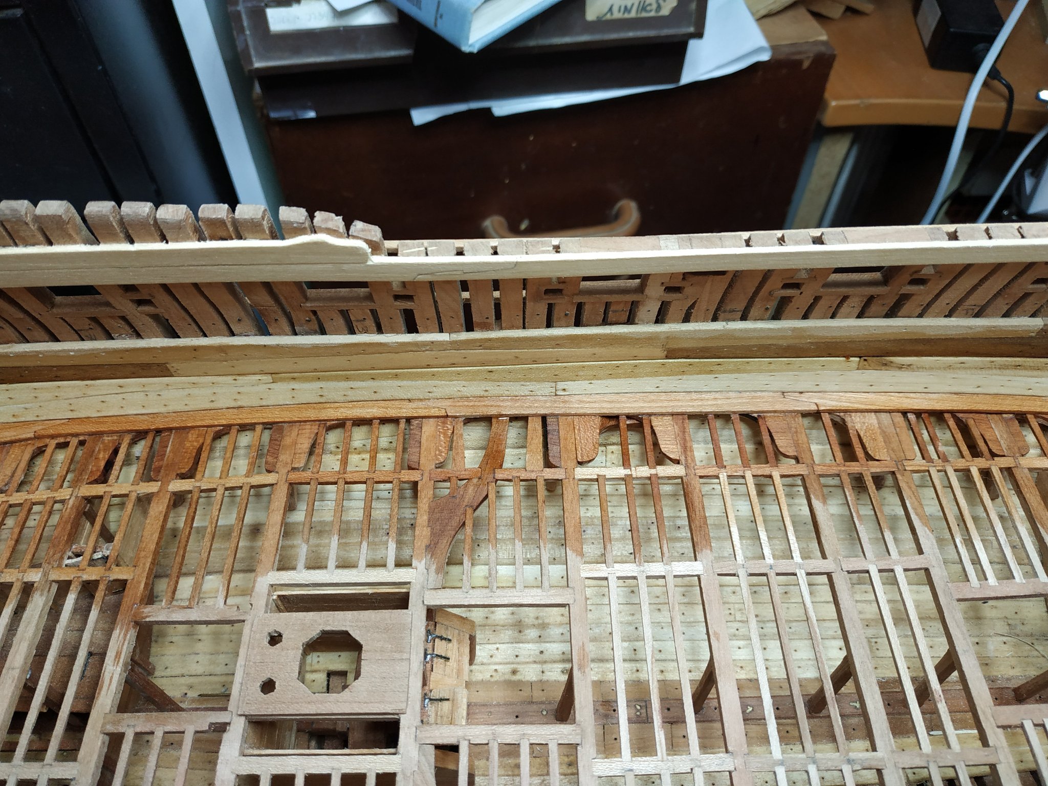
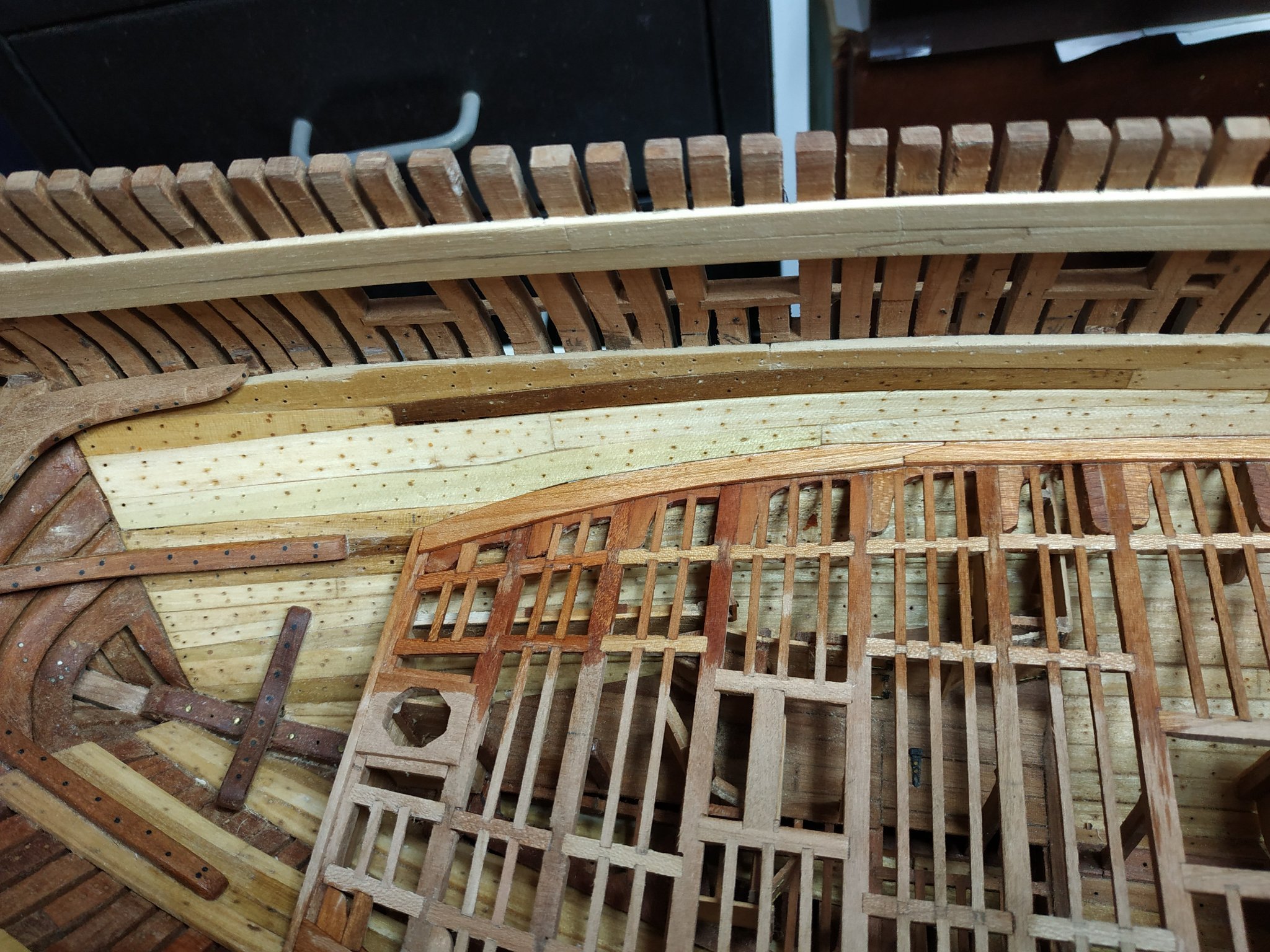
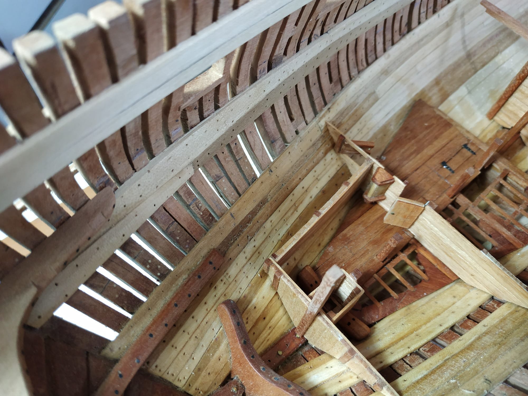
Inner Hull Planking (ceiling) cont. #16 and #17 strakes of 1.6mm thick A stealer is added below the foremost part of #16. I found it easier to chamfer the lower edge of the #16 strakes, rather than the inner waterway. There is an (Air) gap of 1 mm above the #17 sections except the foremost and aft, which are wider by the same amount. The lower edge of this gap is chamfered I also fit the aft #17 first, as the #16 aft shape is more complex/ (I find it difficult to transfer a card pattern to wood, and in this section I have made approximate paper patterns and then fashion the wood directly with sanding sticks and band sander.)
-
Swan-Class Sloop by Stuglo - FINISHED - 1:48
stuglo replied to stuglo's topic in - Build logs for subjects built 1751 - 1800
Very true, however this section, like a few others, suggest several options from which a choice can be made. (I know my limitations and avoid calling on skills which I lack) -
Swan-Class Sloop by Stuglo - FINISHED - 1:48
stuglo replied to stuglo's topic in - Build logs for subjects built 1751 - 1800
Lower Deck (cont.) Again the order of build seems important to decide. The following seems easier BEFORE I start, but we’ll see if it remains so. 1)Waterway 2)Ceiling planking/strakes 3)Bitts,Pump, coamings etc 4)Deck planking.( on previous builds I found it easier to plank to, rather than fit things after) The lower deck waterway is 1.6mm thick, beveled slightly against hull to allow the sitting of the strikes, and towards the planks to match the 1mm plank thickness. To be done after planks are fitted. The nominal width is 6.36mm but are cut from wider pieces to allow for the curve of the hull. Scarf joints as suggested, the foreward 3 pieces are made and fitted first, then the aftmost. The missing piece needs a small adjustment to fit. The foremost piece meets the Deck hook and Eking piece at stem. Aft, I made a small beam athwartship for Beam#19, to neaten-off the deck planks. (made pieces in the usual way-photocopy given plan, stick to blank, extra wood left on inner surface and fitted. They needed surprisingly little adjustment for the curve.)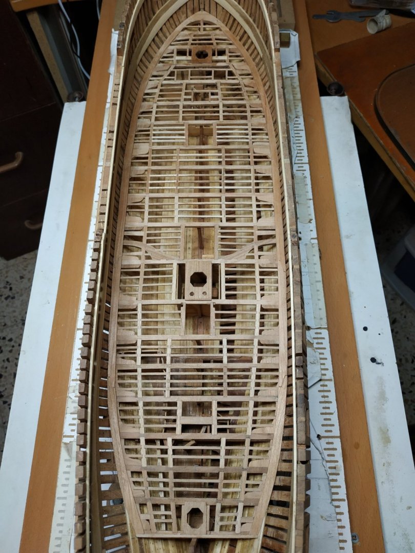
-
Swan-Class Sloop by Stuglo - FINISHED - 1:48
stuglo replied to stuglo's topic in - Build logs for subjects built 1751 - 1800
Thank you. opportunity to again remark on the expertise and work that went into producing such a masterpiece. -
Swan-Class Sloop by Stuglo - FINISHED - 1:48
stuglo replied to stuglo's topic in - Build logs for subjects built 1751 - 1800
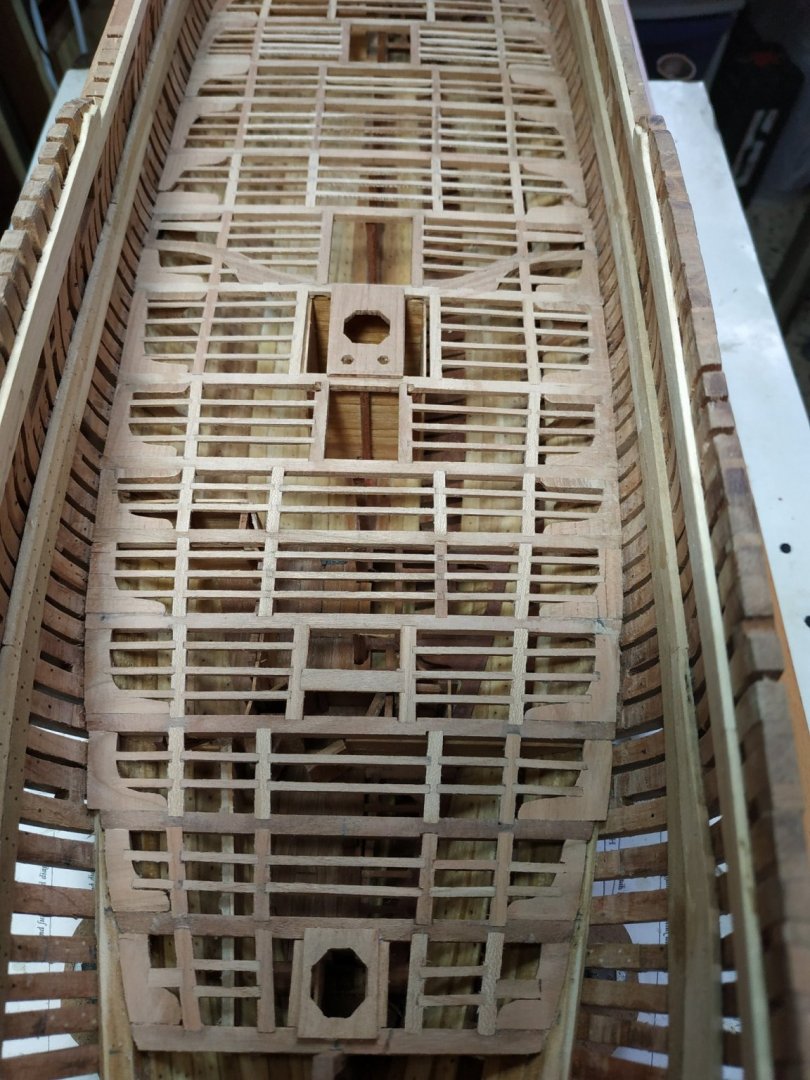
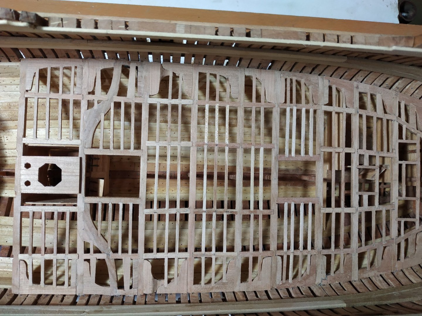
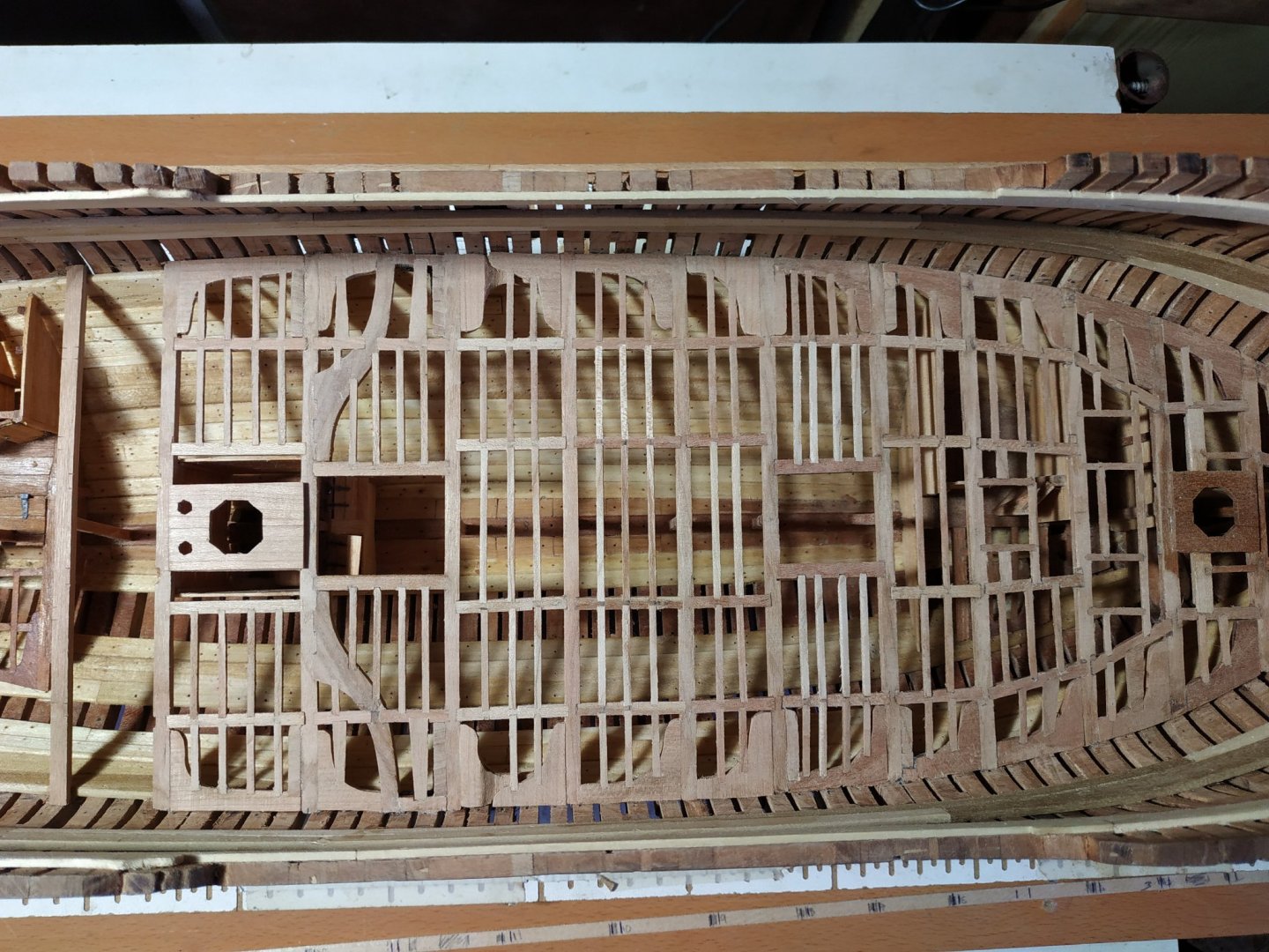
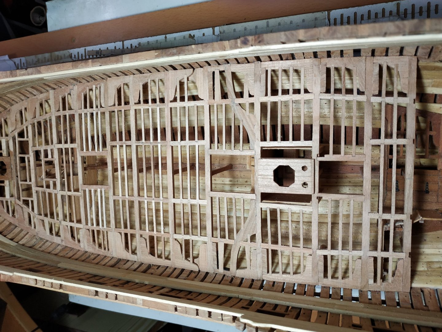
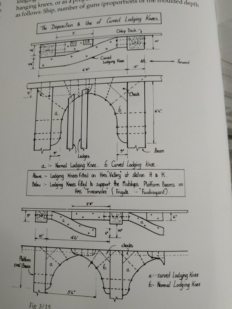
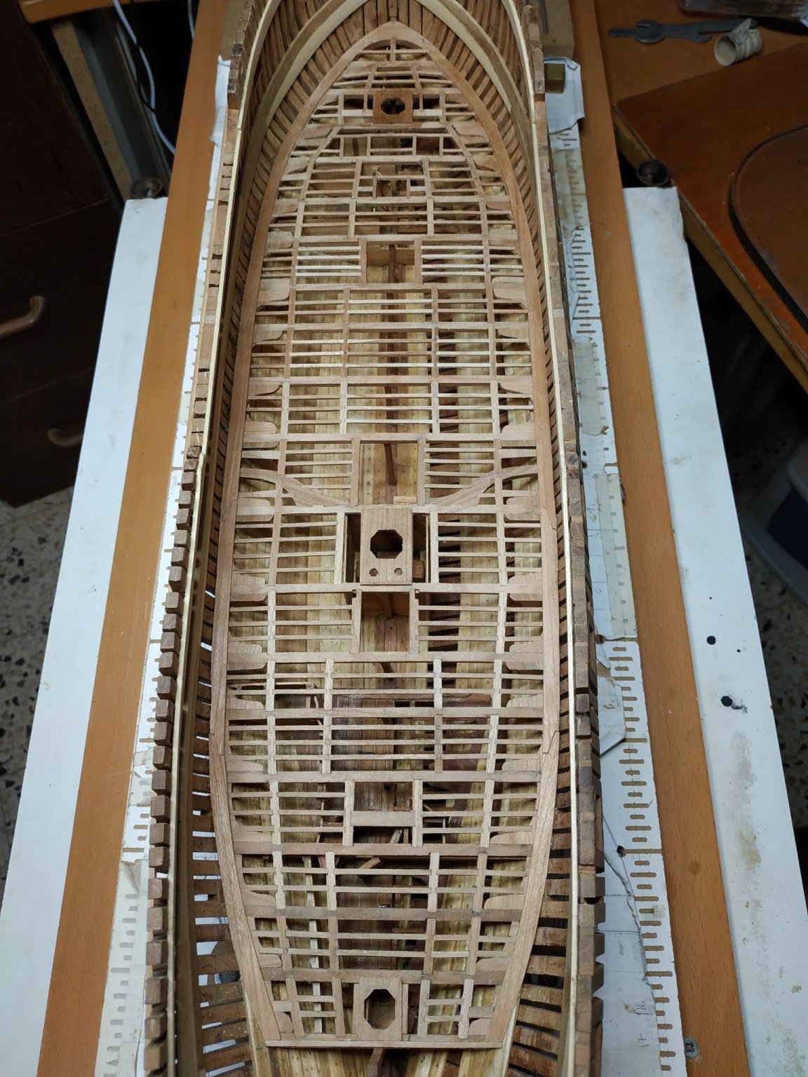
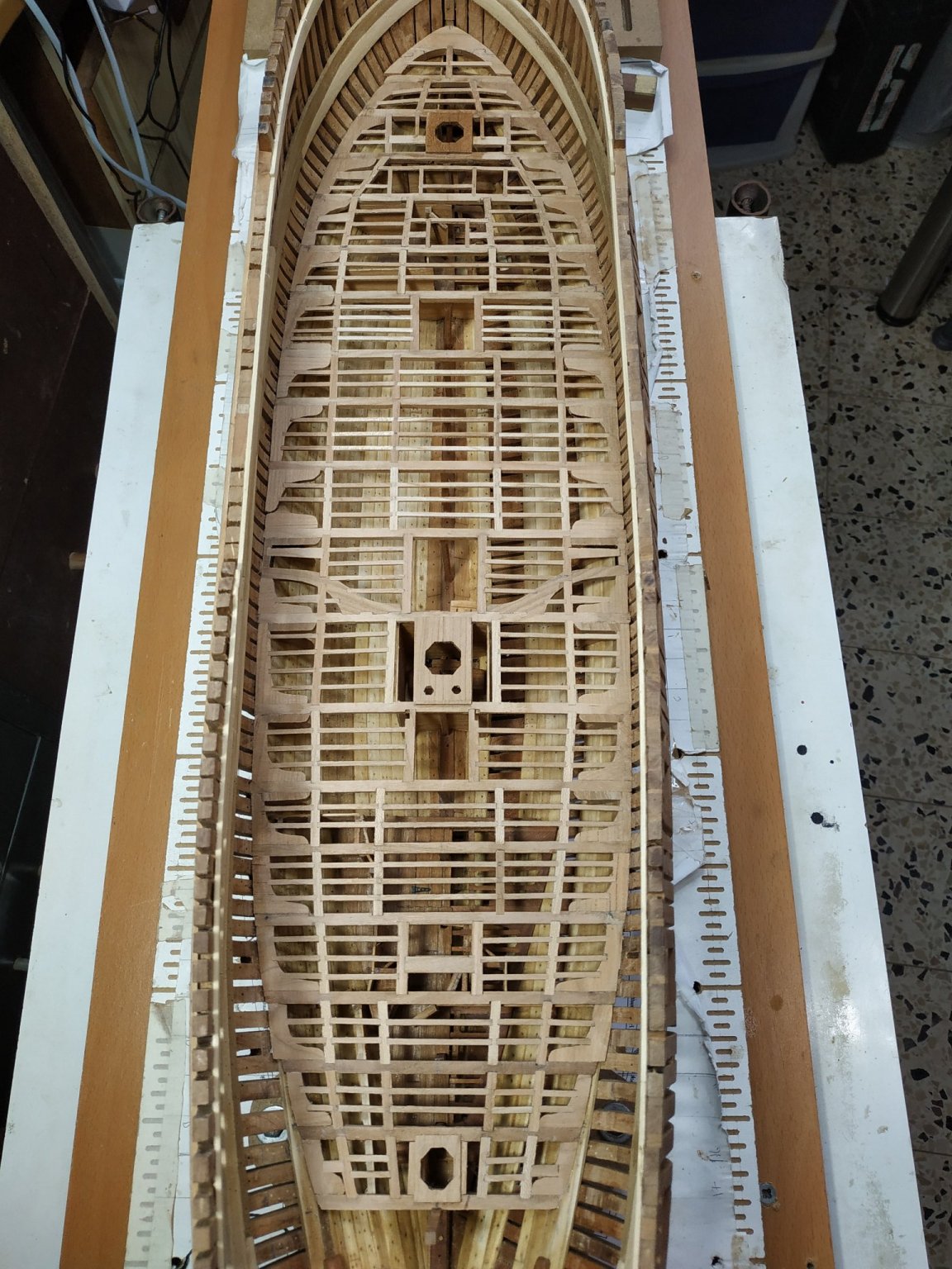
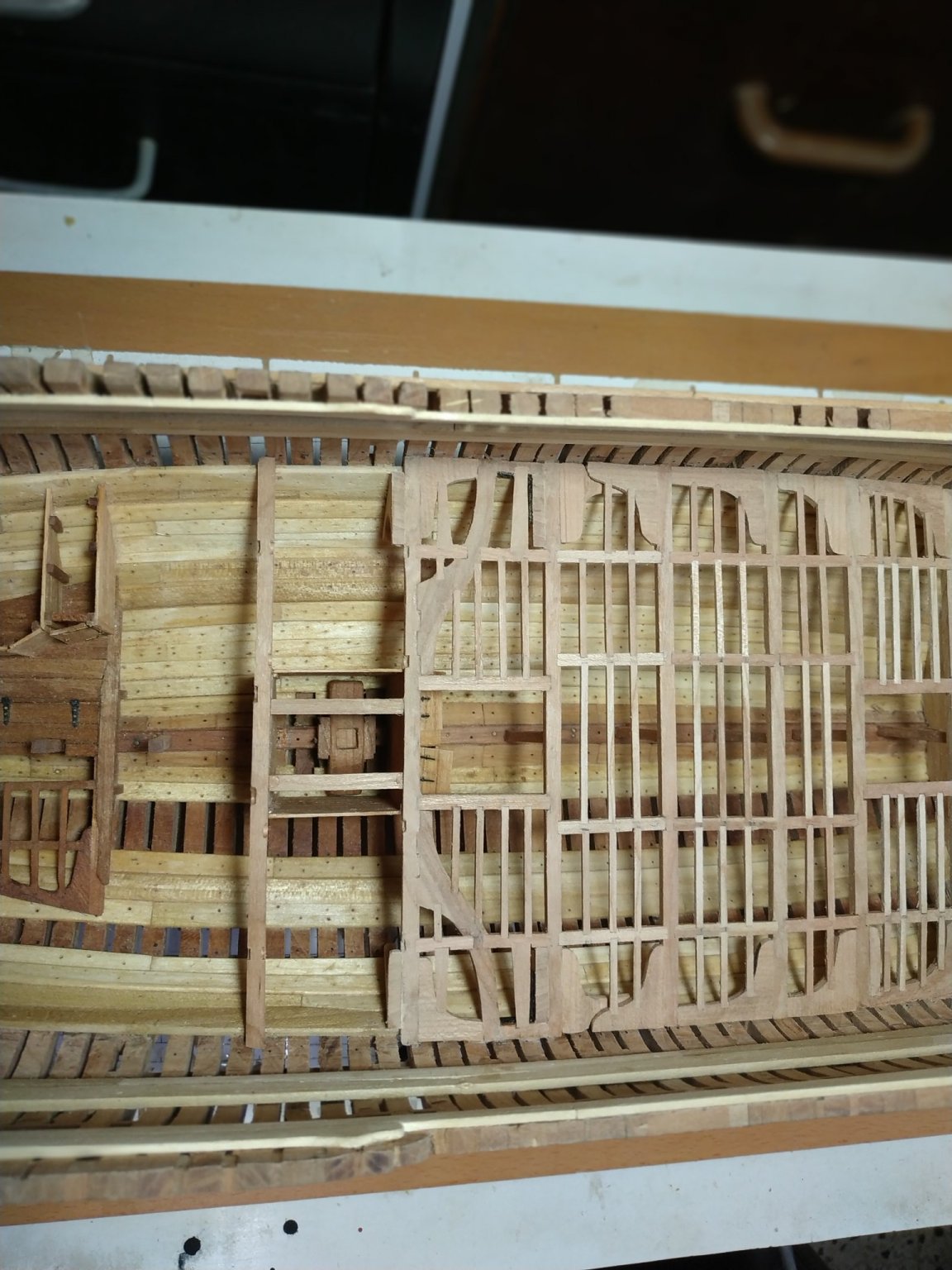
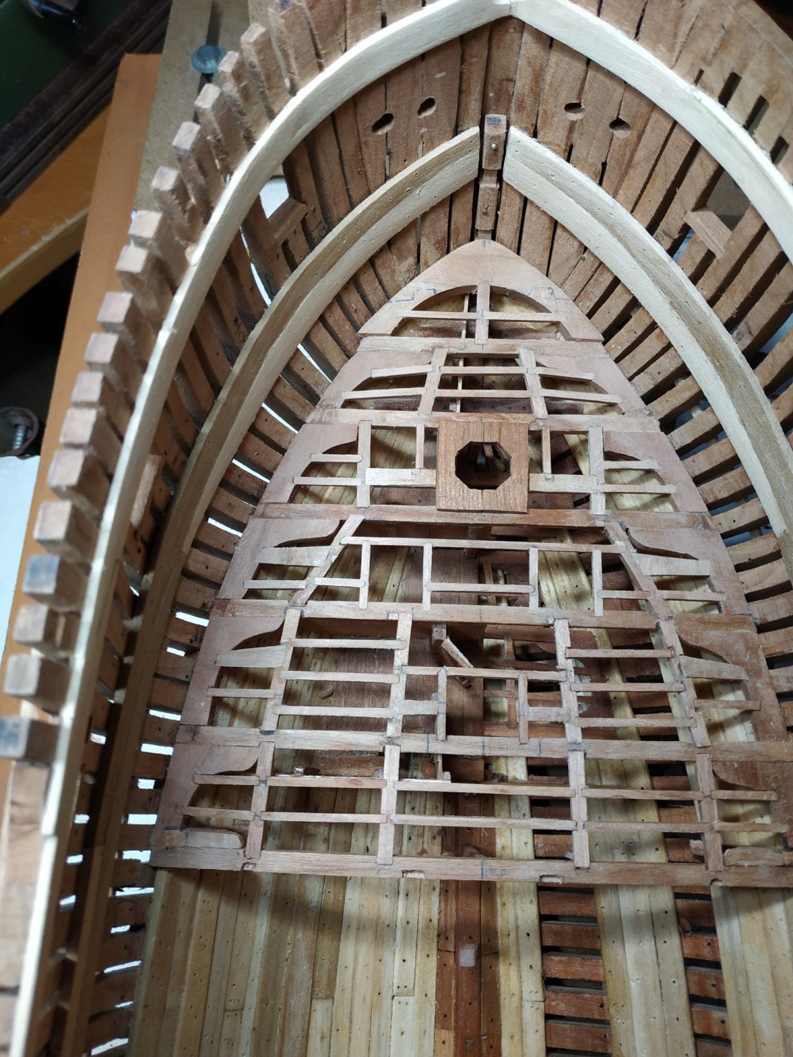
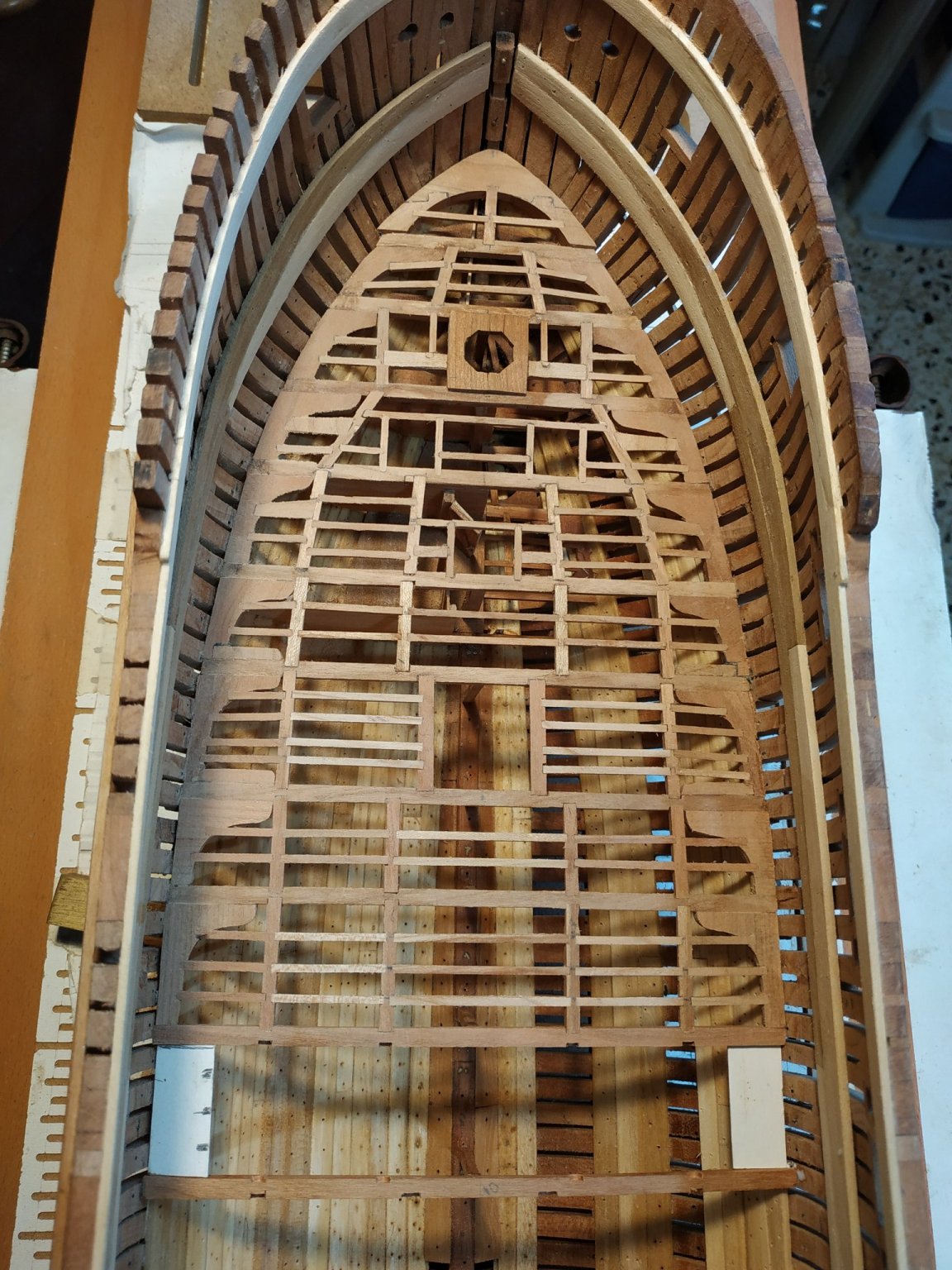
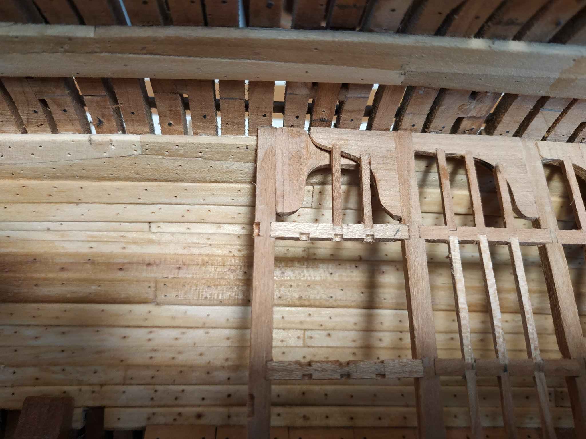
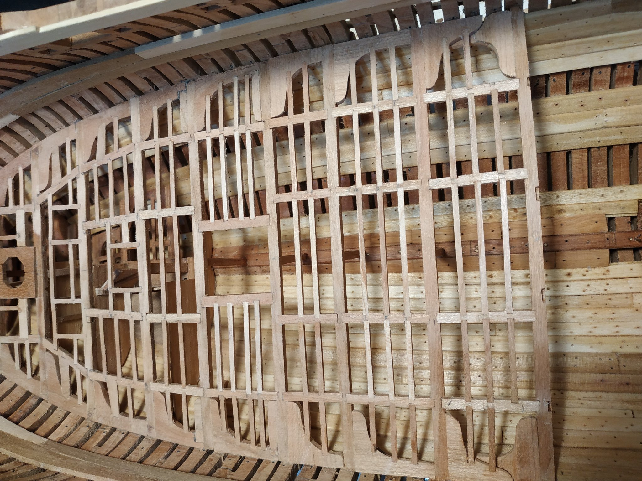
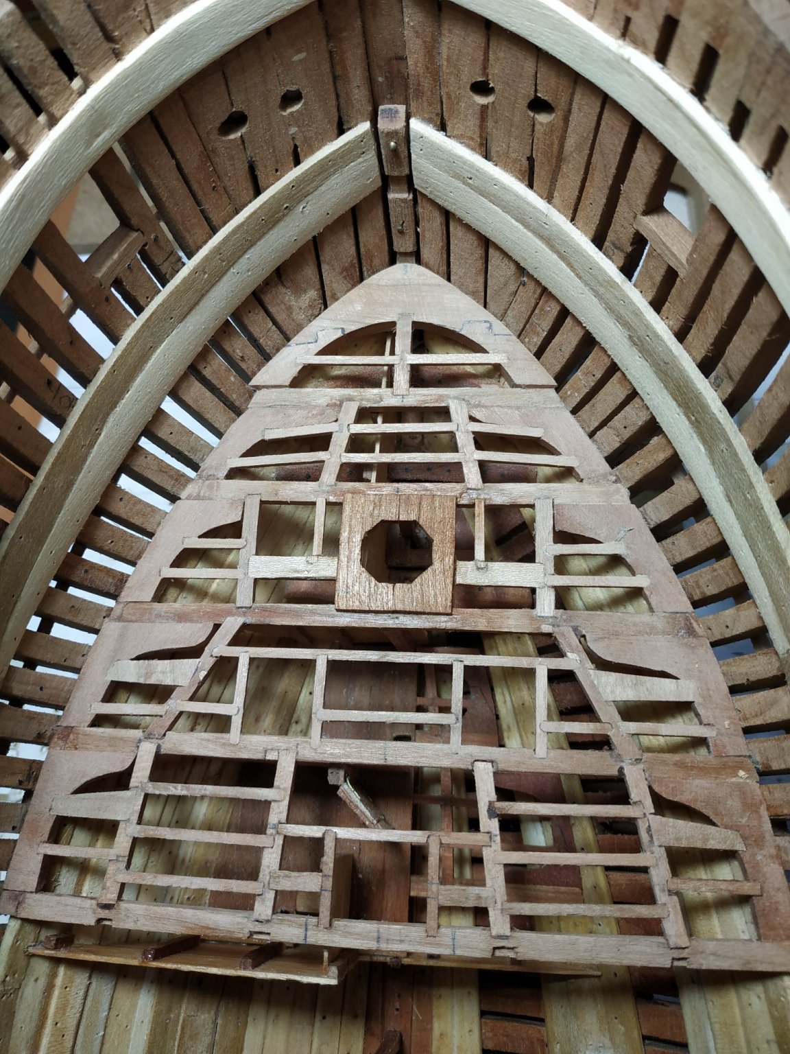
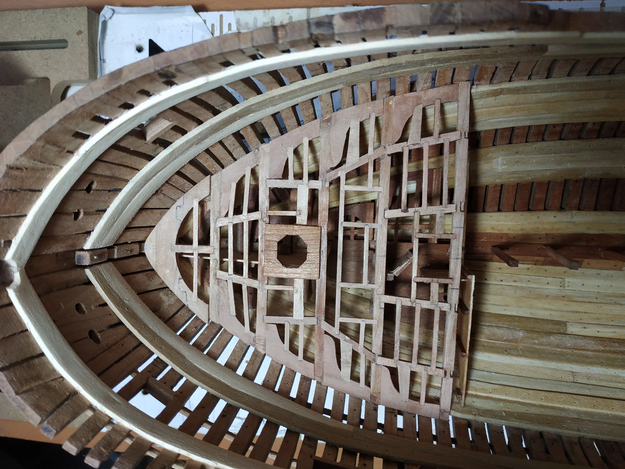
Lower deck beams #14 to #19 The main difference and problem is fitting the beams and lodging knees where the strake of the deck clamp rises more sharply than the deck, and no longer forms support’ as for the previous beams. Referring to other blogs, this doesn’t appear to happen, which was quite depressing until I reread TFFM p222 again, which confirmed, in this at least, I hadn’t screwed up. The lodging knee also need more acute chamfering and narrowing to match the fellows more forward. Noteworthy, the framing of the ladder companionway, carlings 4.0mm and aft ledge 4.8mm. Another problem is the mizzen mast partner sizes- given as 17.5mm wide, 1.86mm thick octagonal mast hole as 11.13mm The illustrated beam pattern shows this as significantly smaller, but comparing previously made partners, and the relative diameters of their masts, simply went with the given dimensions rather than the pattern .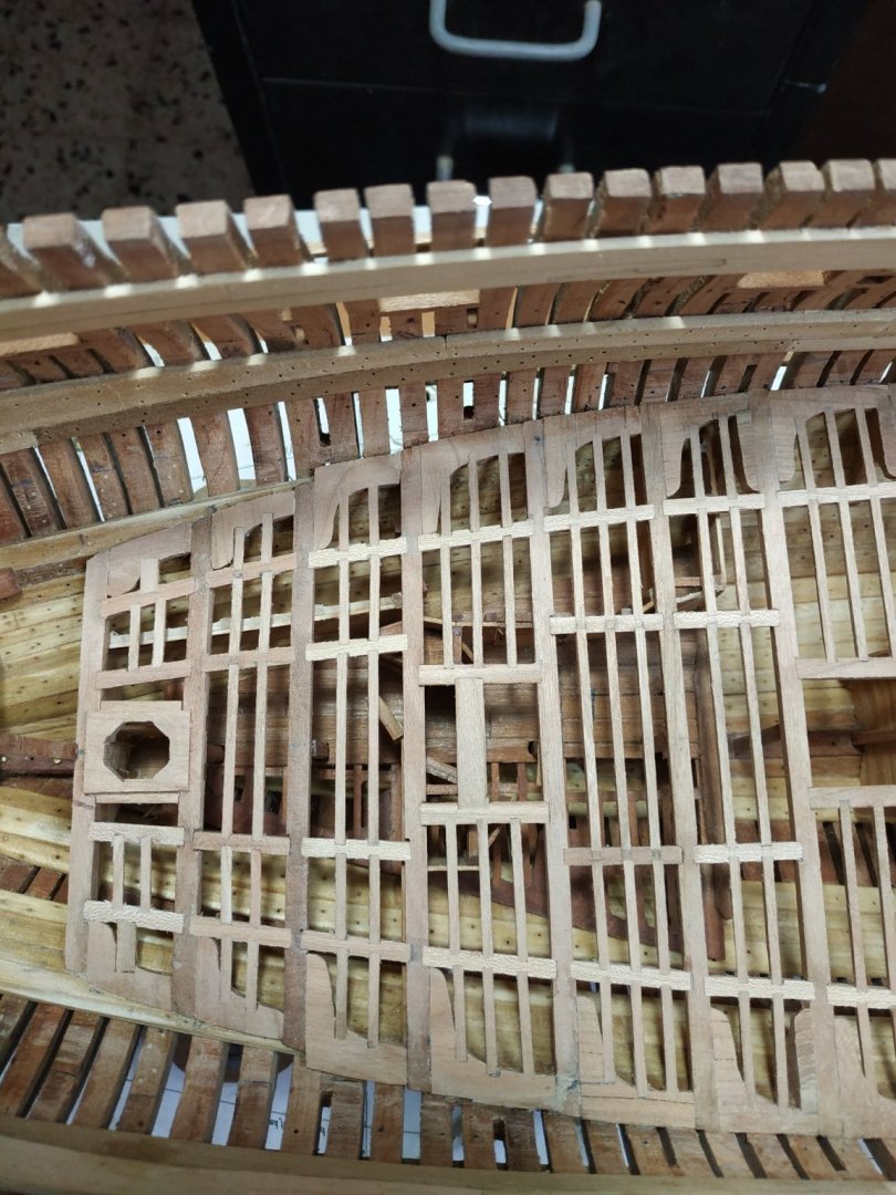
- 475 replies
-
- 10
-

-

-
Swan-Class Sloop by Stuglo - FINISHED - 1:48
stuglo replied to stuglo's topic in - Build logs for subjects built 1751 - 1800
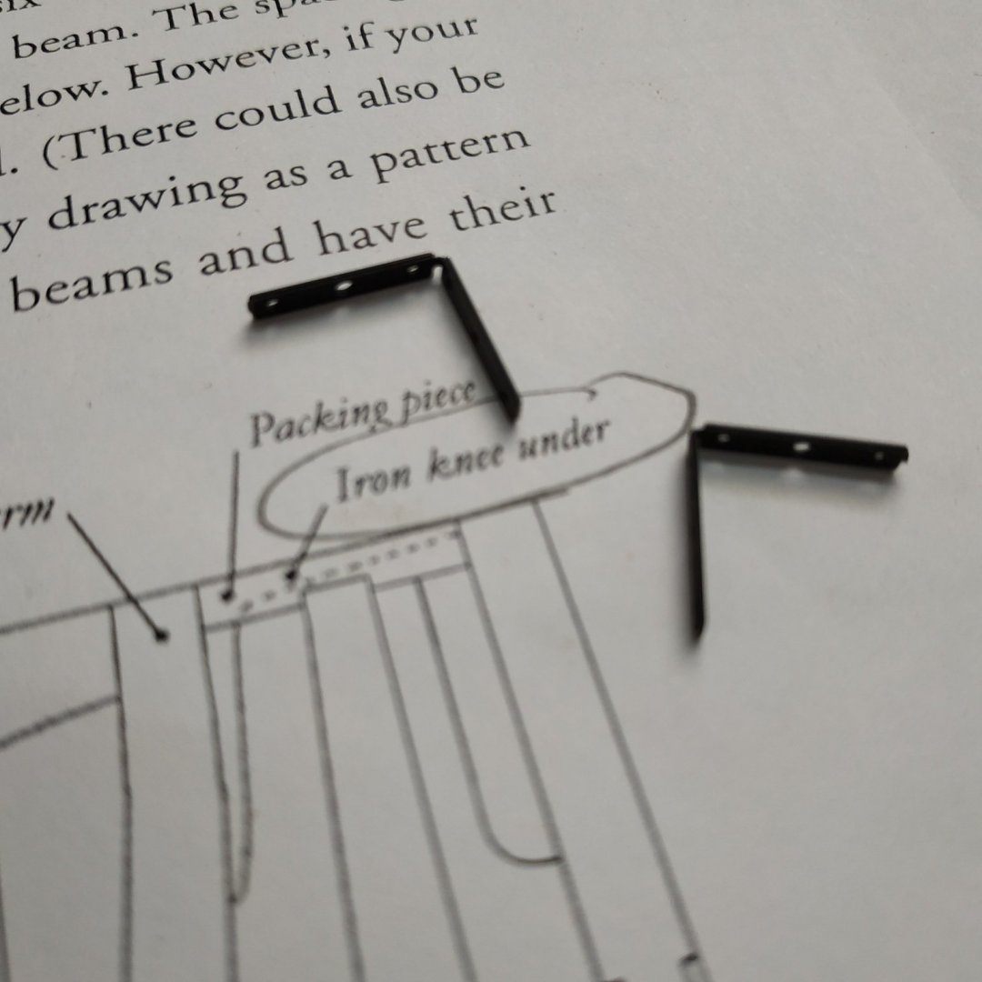
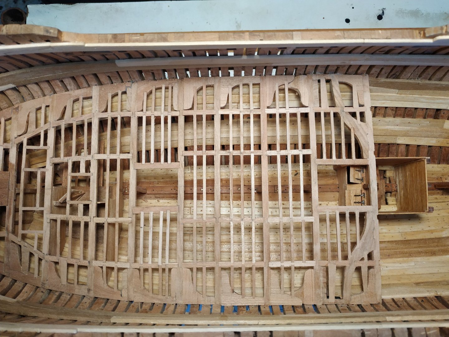
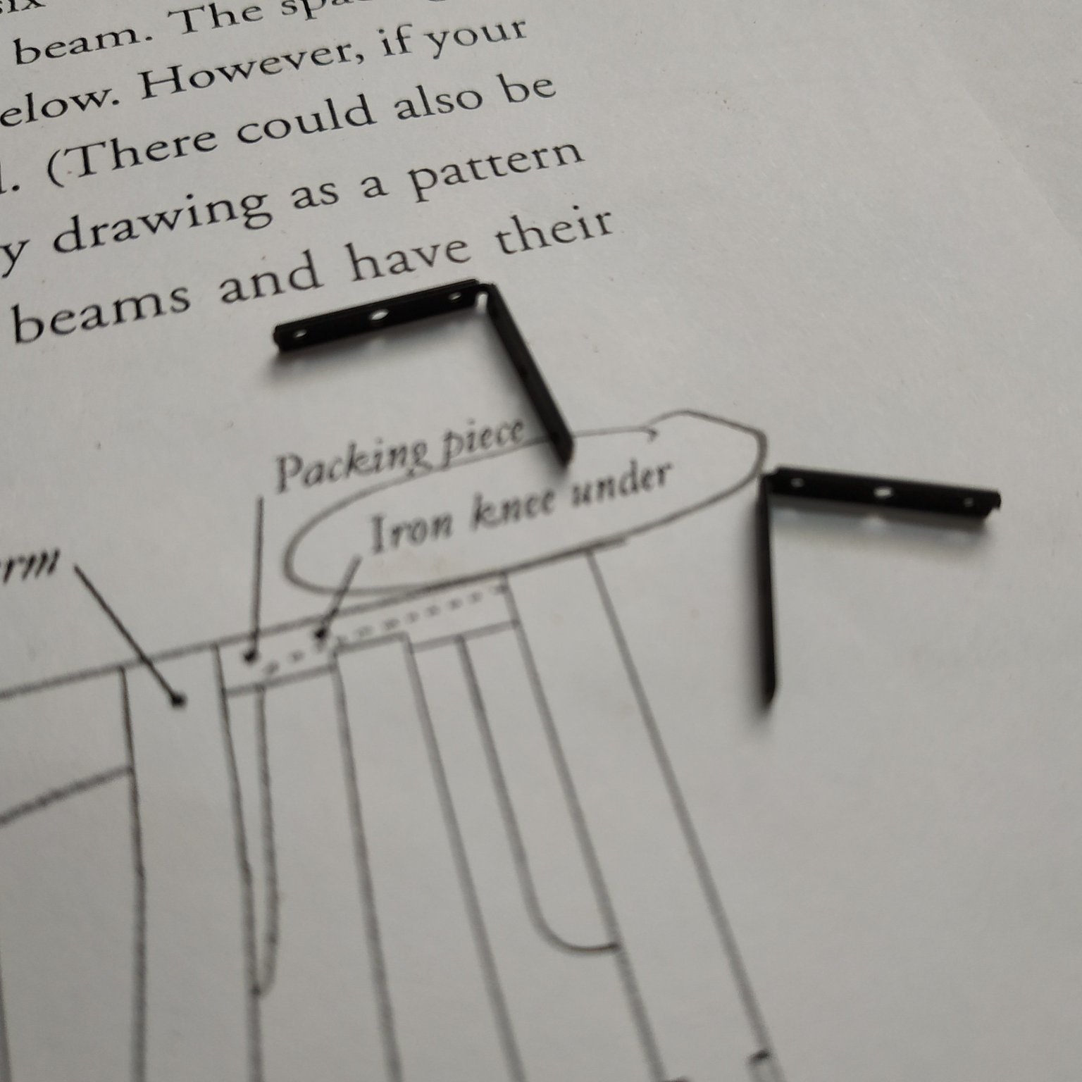
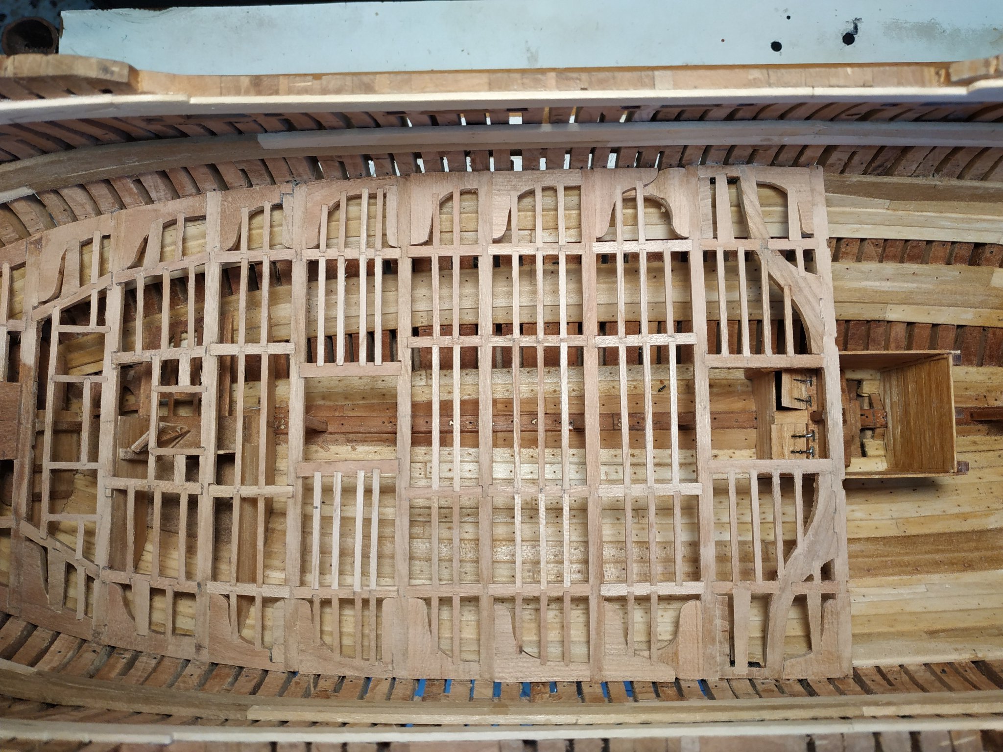
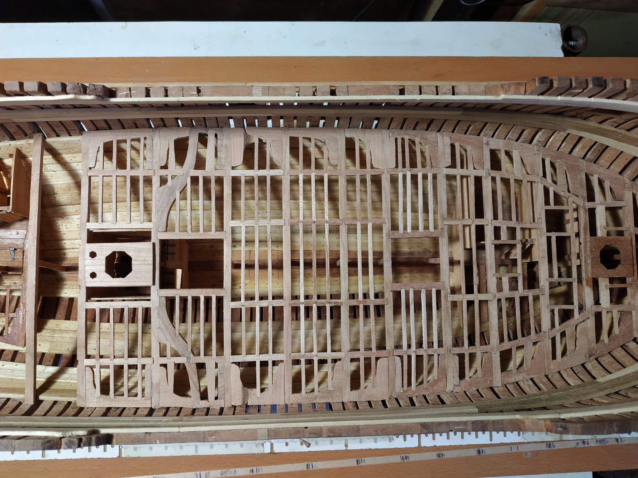
Beams #10 to #11 -Beam arms These, in shape and function, are a cross between a lodging knee and a curved ½ beam. 3.71mm thickness,they are “tabled” (mortised) to a depth of 0.8mm into fore edge of #11 beam. The “foot” attaches to the hull about halfway between the beams. The lodging knee fills between this and #11 beam. Additionally, hanging knees are aft of beame #10 to 13. Between the outer carlings and lodging knee, the ledges are wedge shaped. There is a special packing piece along the hull between the beam arm and hanging knee#10. The inner carling is a frame of the main hatch and therefore 4mm wide. The first problem is thinking about the best order to make and fit the various pieces. I made the beam arms and dry fit them to the beams off the model. Fix beam to model, then beam arms to beam and the hull wall. Remember to let down the foot of beam arm where it sits on the strakes (I forgot at first ). Hanging knees. Packing piece Iron lodging knee - bracing the outer fore beam arm to the packing piece. (Rather than make one, adapted a piece of left-over copper) I then got confused between the hatch carlings and support of mast partners. At first made the mortises to match those on #9, then thought I’d forgotten to make the to underlap, repaired the mortises, milled under #11for the underlap, fitted the carlings, rechecked, realised that I was looking at pattern for beam #12, looked around for someone to blame (but wife had stayed in the kitchen all morning) undid the repairs and repaired the unnecessary mortises. Phew!! ( The great thing about wood and PVA glue is the ability to repair and redo- a picture is included as an example.) Beam #12 Main Mast partners similar to the fore partners. These are the carlings that underlap that previously caused confusion. Overall width 22.26mm. Thickness 2.12mm and let down 0.53mm Octagonal hole 15.9 mm diam. 2 additional small octagonal holes either side, size 4.77, centred 5.3mm from centre line (for part of pump mechanism) I thought I’d made another error as the carlings don’t cover the shotlocker walls, but double checking measures, this was not supposed to happen. Beam #13 Slight intoeing of outer carlings noted, parallel with narrowing of hull. The thicker 4mm inner carling is notched at fore outer end- the main jeer bitt pin-this extends slightly into the #12 beam. Beam #14 Main variation is the sharper curve of the hanging knee to match the shape of the hull. I also shortened it a couple of mm to match.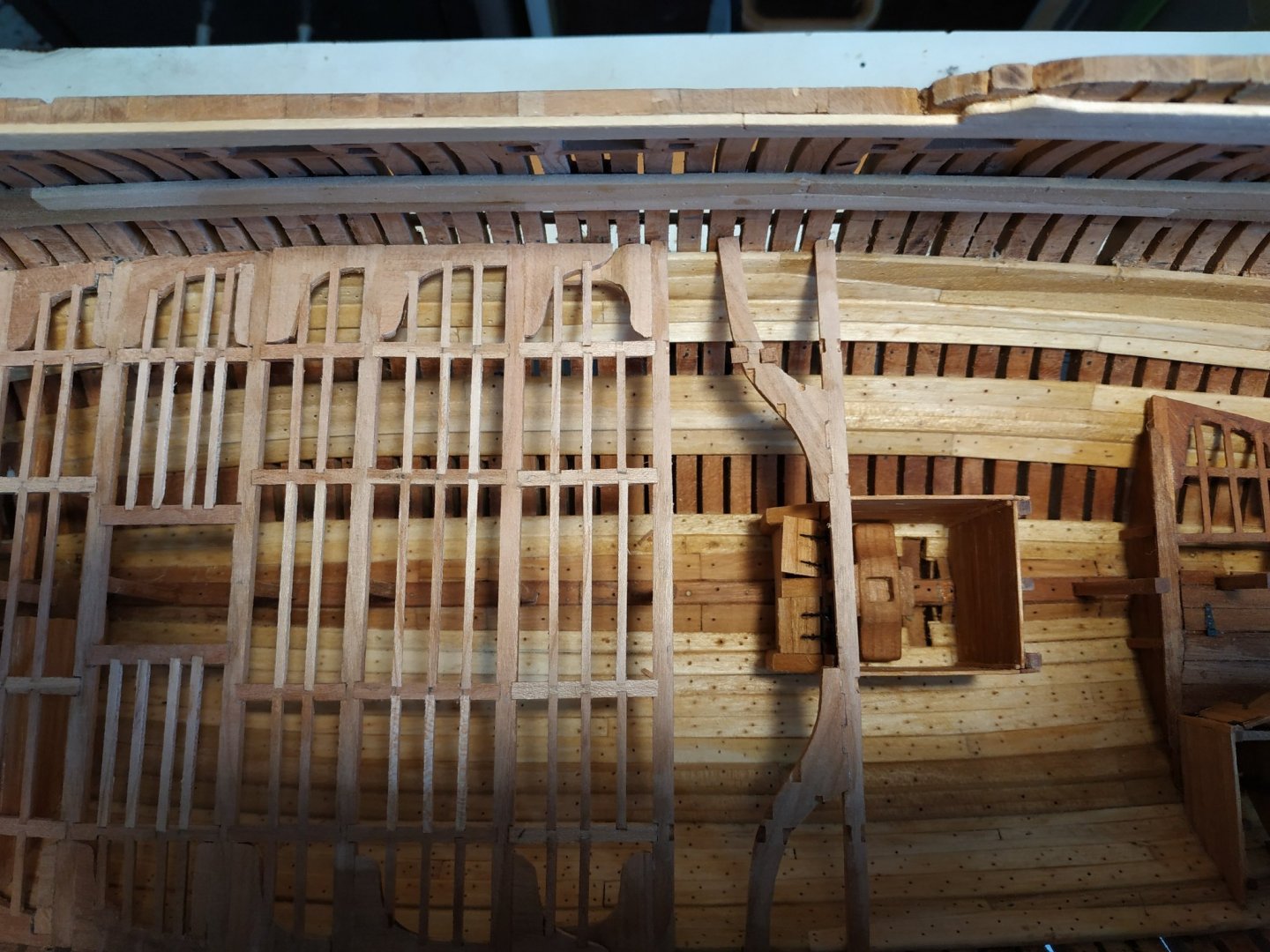


-
Swan-Class Sloop by Stuglo - FINISHED - 1:48
stuglo replied to stuglo's topic in - Build logs for subjects built 1751 - 1800
Thank you. Its me being mean and using wood I have. -
Swan-Class Sloop by Stuglo - FINISHED - 1:48
stuglo replied to stuglo's topic in - Build logs for subjects built 1751 - 1800
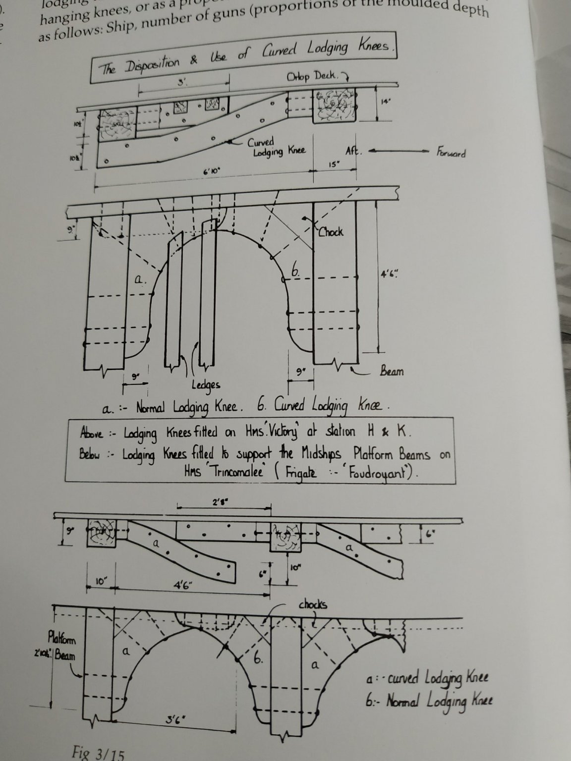
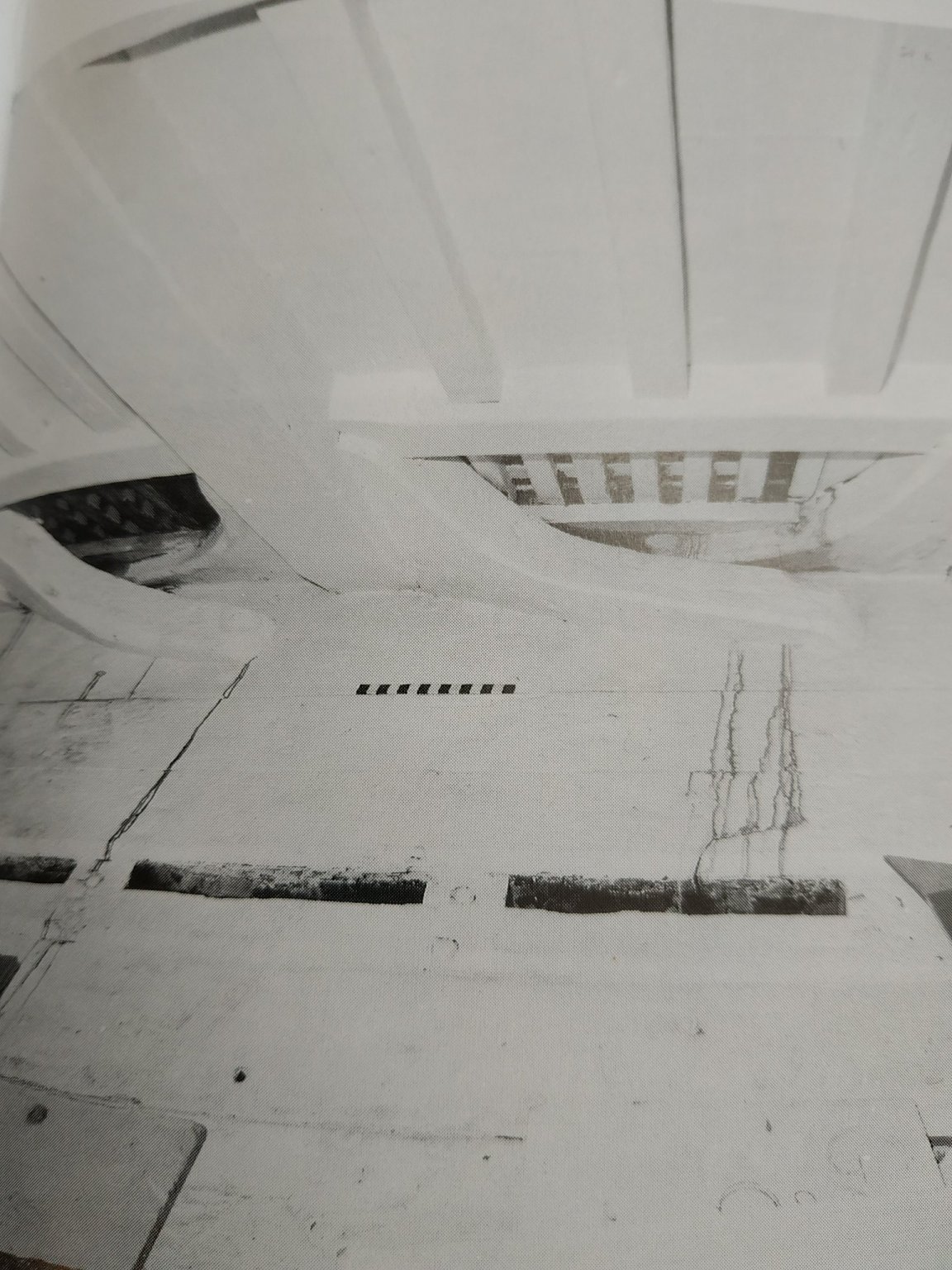
Lower Deck Beam #6 First of the HANGING knees. “comma “ shaped vertical piece, foreward to the beam. 3.18 thick, side arm against hull (and shaped to fit the different thicknesses of strakes) and a shorter arm along the beam. The pattern in TFFM acts as a good starting point and I used the edge of band sander and a file for shaping. Because the lodging knee sits against the frame and the hanging knee is against the strakes, I found it easier to mortise the former, although TFFM shows the hanging knee to be notched. Checking other blogs, a similar decision seems to have been made. Some tapering of ends of arms is also mentioned. Aft to the beam, the inner pair of carlings form the side frames of the foreward hatch. They are wider than usual- 4.0mm #7 Beam. There is also a hanging knee The inner, wider carlings form the aft of forehatch frame. Ledges as before #8 Beam Found the pillar incorrectly positioned while dry fitting lodges and moved accordingly. ***Measuring TWICE is not enough. Interdependence requires frequent rechecking with as many reference points as possible*** #9 Beam-#10 Beam. This is a transition zone after which the lodging knees are set aft of beams. It therefore has both! Various options are given, and reference made to a Peter Goodwin book. Apart from a scarph joint, suggestion is a CURVED aft knee, like a horizontal stretched “S”. This appears to give some support to the beam, but leave a small, ?unimportant, gap in the seating of the waterway. In any case the fore lodging knee needs fixing first. The aft tip was thinned for easier passage of the underlying aft lodging knee. I first took a 6.25 blank, made the shape but found that again the presence of the strakes made positioning too difficult. Placing the aft portion against the beam and the hull frames, and the adjusting for strakes thickness while it angle down to pass below the fore knee, was too complicated. So I made 2 copies of the aft knee of normal thickness, and removing the fore part of upper, aft part of lower, some generous chamfering, and made something I think reasonable

-
I have the small proxxon and the proxxon FET. I am unhappy with the latter for various reasons including the longitudinal stop moving when tightening the toggle screw (handle). Also, with the blade guard in place this stop cannot be less than 1cm from the blade. (working from the right as I do). In fact, using the smaller proxxon is much better for thinner strips eg 1.6X1.8mm. I am seriously thing of ordering a Byrnes. I would very mush like to hear comments and advice.
-
Has anyone experience with or advice about the use and usefulness of turbo carvers for ship modelling -NOT specifically carving
-
Swan-Class Sloop by Stuglo - FINISHED - 1:48
stuglo replied to stuglo's topic in - Build logs for subjects built 1751 - 1800
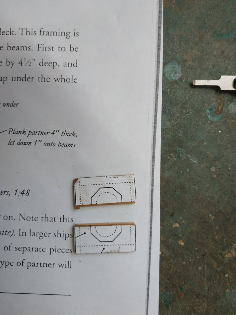
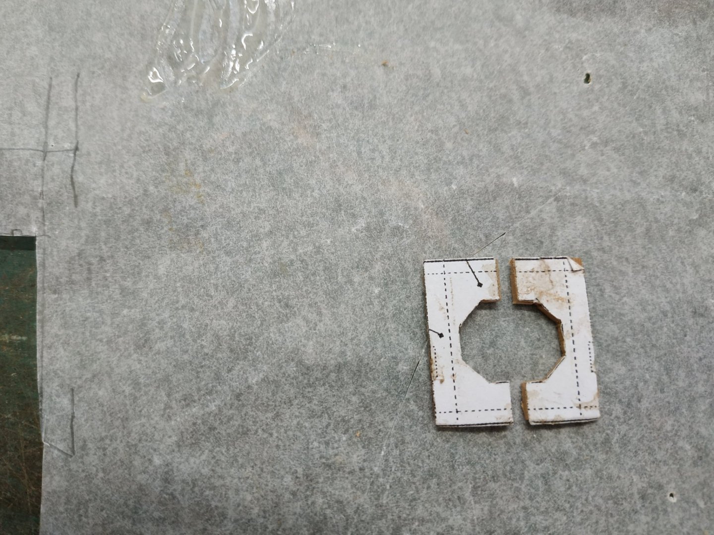
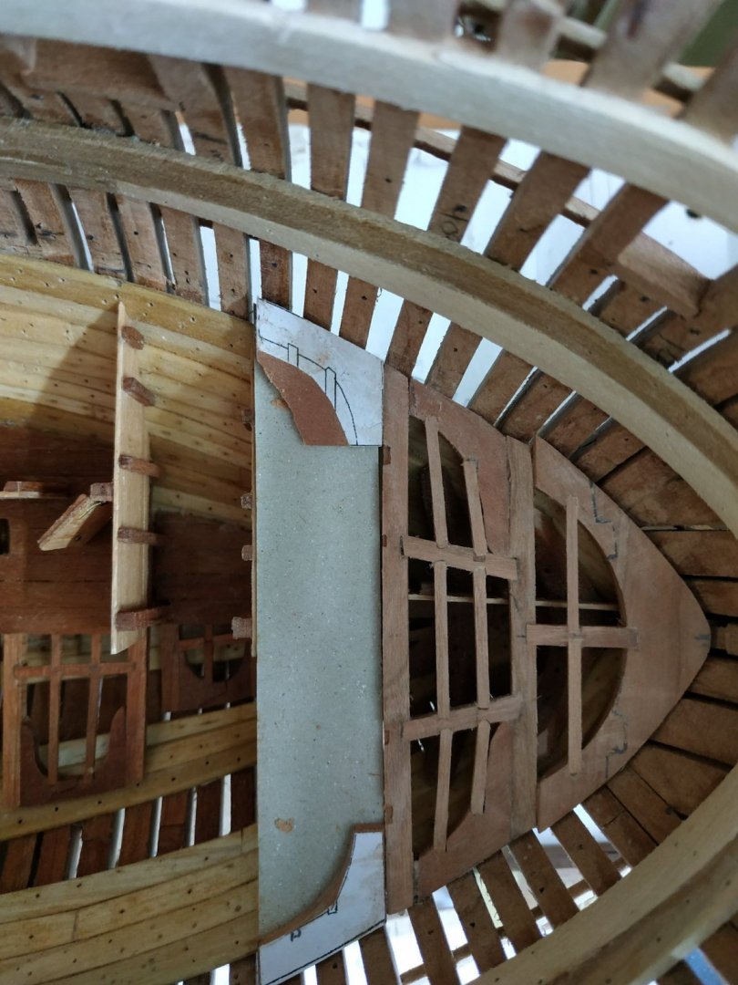
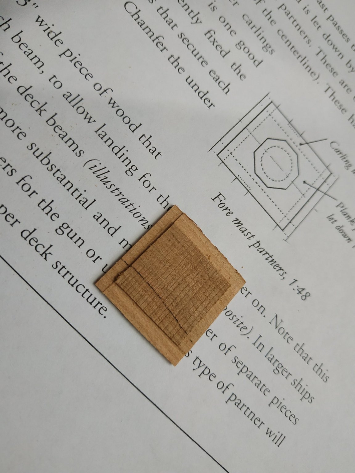
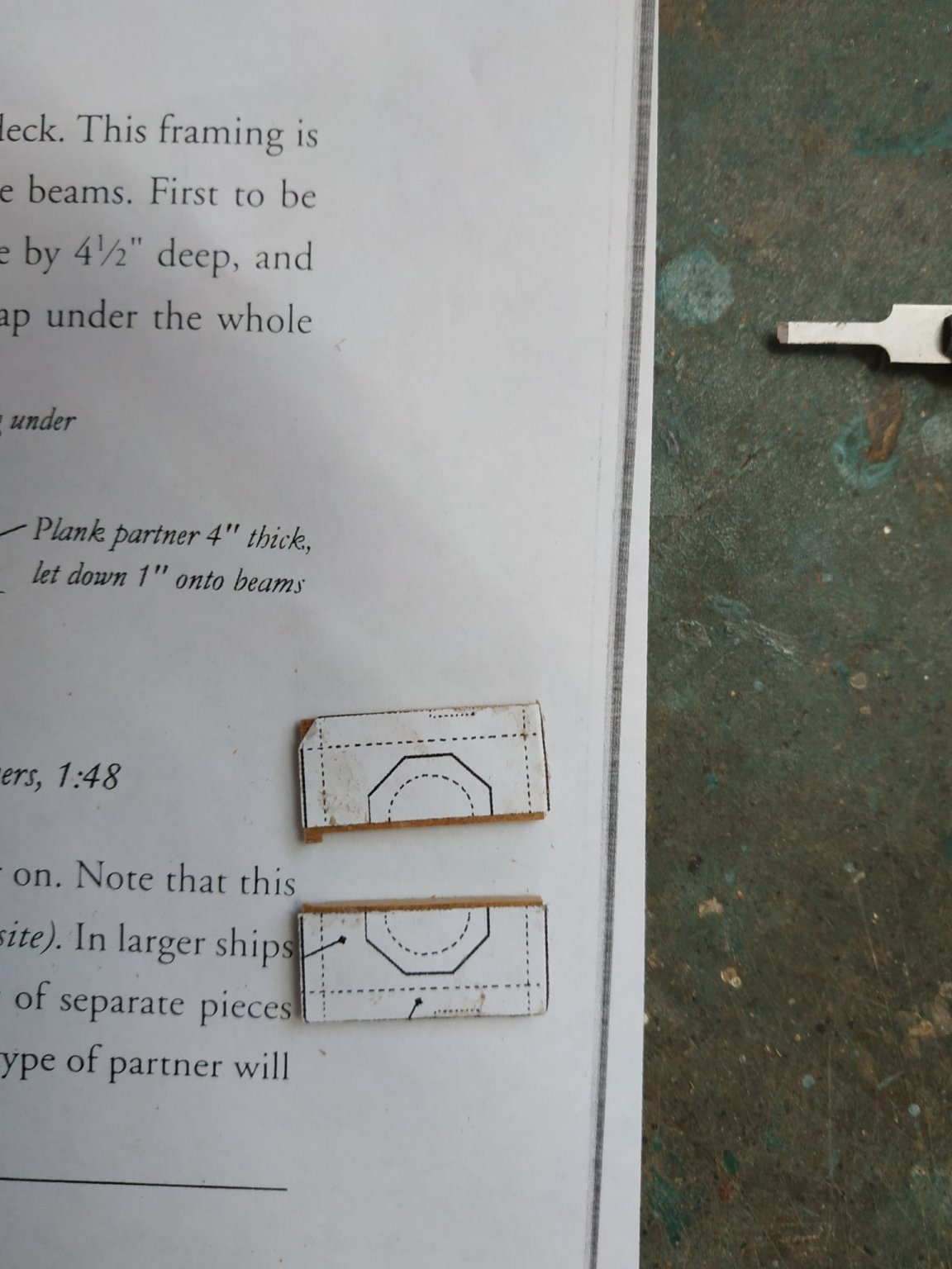
Plank Partners Between Beams #2 and #3 20.67mm wide, 2.12 mm thick with let down 0.53mm on beams and supporting carlings. I made it from an oversized blank, milled the let downs, split the pattern in half so as to more easily cut and file the required central octagon, and then placed 2 sides together when fitting in place.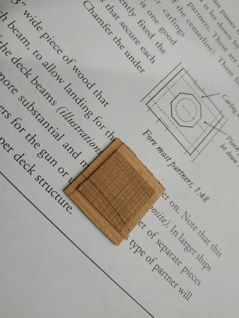
-
Swan-Class Sloop by Stuglo - FINISHED - 1:48
stuglo replied to stuglo's topic in - Build logs for subjects built 1751 - 1800
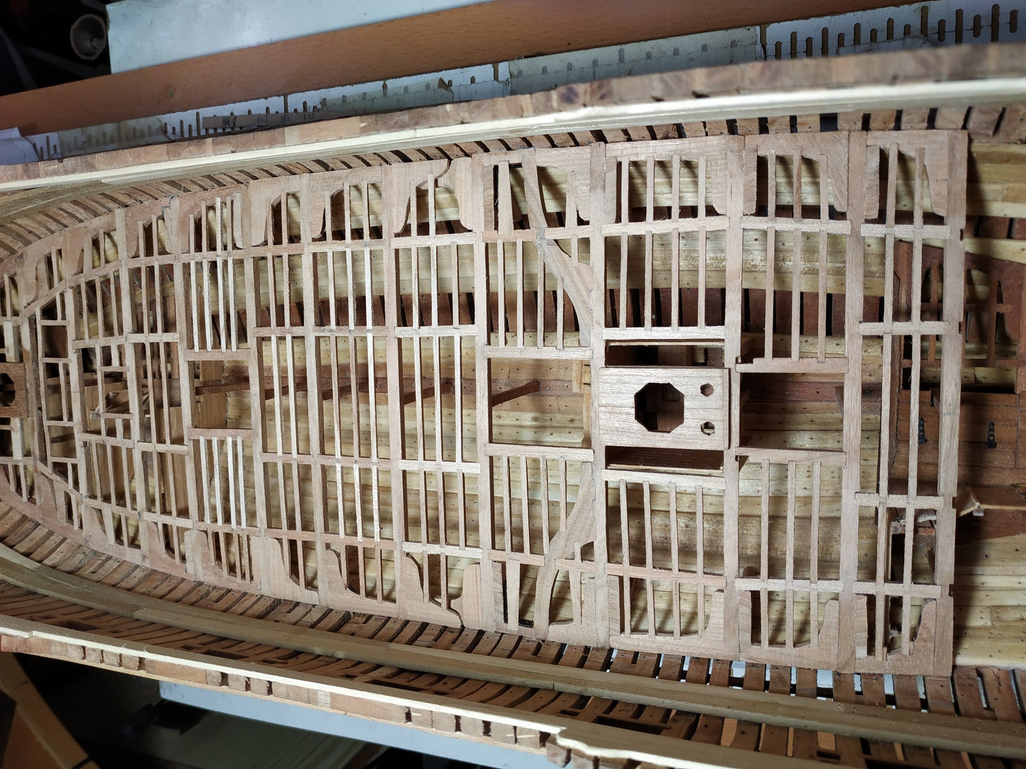
# 3 Lower Deck Beam. Forms Aft framing of foremast partner, and outer carling. On either side of the partner, is a scuttle, framed by this outer carling, ledges and a wider (4.34mm) ledge. Onl after making and fitting the parts, I realised that I forgot to ensure the scuttle framing was squared, and this was repaired. #4 This was the only beam that I had already fixed. This sits on the middle wall of the foremost platform and pillar previously fitted. On checking distance between #3 and #4, obviously something is very wrong. I now realise that the pillar has been wrongly positioned, mostly because it was not recessed into the 3rd foreplatform. Good old alcohol (on PVA) and able to remove and remake or adapt the position of the pillar and related walls so as gap only 2mm less than the plan. Other structures, such as mast and Bitts are unaffected . Only 1 pair of carlings and ledges which also form a scuttle either side. The fore outer ledge is wider and wedge shaped. The making of these pieces also show the disadvantage in milling “off”model. The slightest inaccuracy becomes obvious when the parts, particularly ledges, are supposed to be parallel. #5 Outer and inner pairs of carlings with a central scuttle, framed by ledges. Pins of the Bitts mortised give support to the beam rather than a pillar. !!!! WARNING!!!! Viewing diagram the next set of beams, I see these pins are aft of #5, yet I thought they were fore. Reviewing the various diagrams, especially p245 (bulkhead layouts on fore platform), I assumed beam#5 sat on the aftmost bulkhead and as the pins were to the fore of this, so would they be to the #5beam. A more careful referral to the profile plan shows this with obvious hindsight. Therefore, bulkhead removed, 5mm extension to aft of platform,and then remade to fit the new position.


-
Swan-Class Sloop by Stuglo - FINISHED - 1:48
stuglo replied to stuglo's topic in - Build logs for subjects built 1751 - 1800
LOWER DECK Consist of:- Beams (already made)4.24mmx3.18mm Hanging Knees - thickness 3.18 Lodging Knees - 2.92mm Carlings-3.18mm x 2.39mm (some exceptions) Ledges -1.86mm x 1.60mm (some exceptions) My intention is to mill as much as possible off-model The Lodging knees- athwartship arms as shown on patterns, the fore/aft according to gap between beams, and shaped to fit against hull. The Hanging knees- to the fore of beams in the fore half of the hull, aft to aft beams. Only present on beams 6,7,10,11,12,13 (10+11 with additional iron beam). #1 beam. Already fixed with breast hook #2 positioned as per plan- in my case 15.5mm gap. This beam also forms the fore part of the foremast partner.(A rectangular structure around the foremast).The mortises are prepared for a pair of carlings foreward and a pair “outer” carlings aft. Also aft, the inner carlings are under the fore/aft partners, and half UNDERlap the whole width of beams. The lodging knees,athwartship arms 22.26mm, shaped and camphered to match the hull. Also athwartships, ledges connect the lodging knees to the carlings..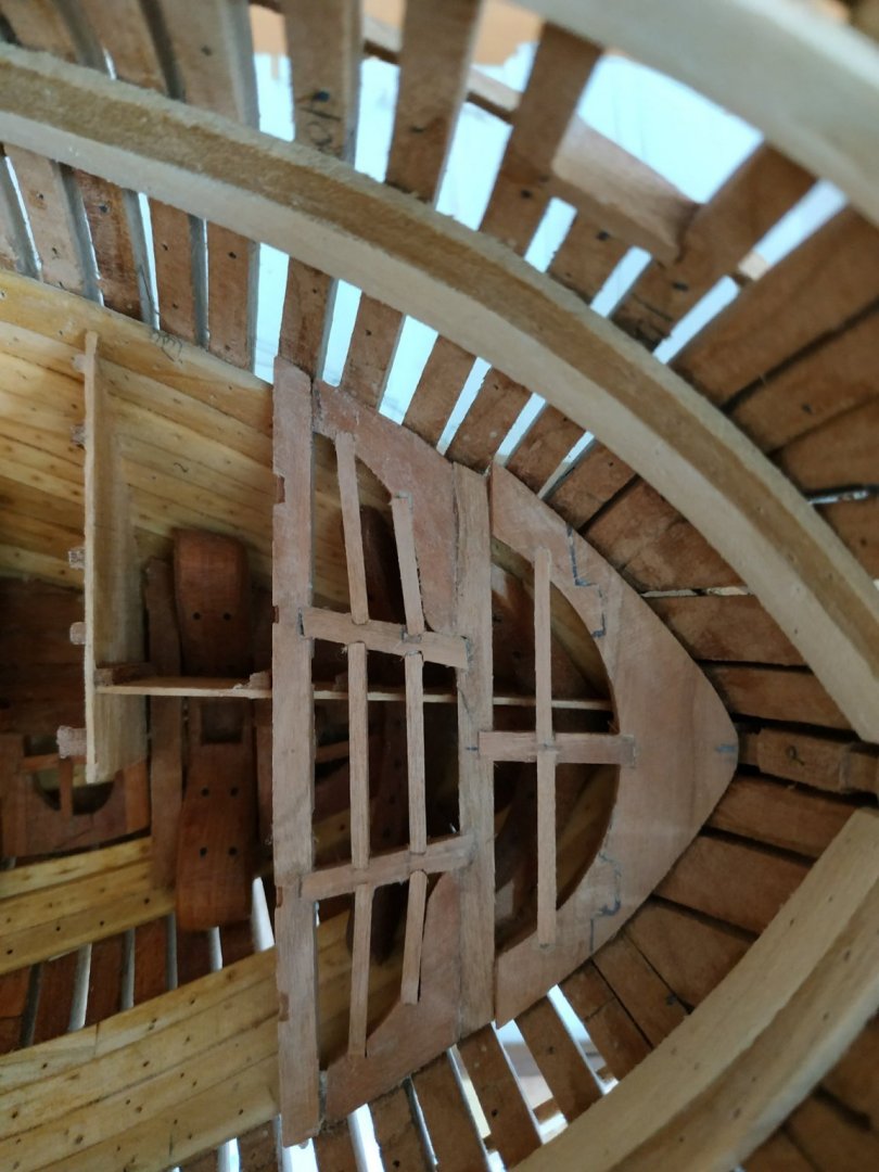
-
Swan-Class Sloop by Stuglo - FINISHED - 1:48
stuglo replied to stuglo's topic in - Build logs for subjects built 1751 - 1800
Lower Deck Hook (start of new chapter!!) A breast hook. Said to be almost horizontal, as shown also by my plan. But this means the precut mortise in the stemson too high. Double checked and can’t find the error. This hook extends from the stemson to #1 deck beam (whose position must be determined first)via wings or Eking pieces. As warned, the plan needs significantly modifying. My plan shows a thickness of 5.3mm (TFFM 6.4)-but also needs “letting down” Because of this thickness and curve of the hull, a cardboard blank is difficult to shape. I would think a layered or ply approach would be easier, but I bit the bullet and roughly shaped oversize blanks with scarph joints for the Eking pieces. The underside of the piece needs severe chamfering to fit the deck clamps. I felt the angulation foreward too extreme and pared down the foremost deck clamps. The excess mortise can be filled later. The #1 deck beam forms a seat for the end of the planks, and therefore forms a step 1.16mm below the upper surface of the hook. This surface also parallels the deck curve. After poor results with previous efforts, decided to mill mortises while off-hull.
-
Swan-Class Sloop by Stuglo - FINISHED - 1:48
stuglo replied to stuglo's topic in - Build logs for subjects built 1751 - 1800
Fore Platform Bulkheads. Although TFFM says similar to aft, plan and Vardas seem to show a continuous wall rather than above and below a “lip”. Perhaps because there the bulkhead above the platform is incomplete or its’ beam sits below this lip In any case, rather than separate upper and lower segments (and different wood) the aft bulkhead of the fore platforms is made as the walls. It also is separated from the fore platform to allow room for the uprights of the Bitts. There is a central gap (without a door). Door only to aftmost room-access to others via scuttles. Note also no pillar to #5 lower deck beam. Stanchions are 2.12 mm square.-some are already located where recesses already made in the platform planking. (the rabbeting suggested as a possibility will be omitted) Rooms on the port side looking foreward are Blockroom,Coal hole and Boatswain’s store room. Middle bulkhead-extends across from side to side. Against and supported by the #4 pillar. Similarly, the fore bulkhead, has no gap or door. Finally, a fore/aft wall from this bulkhead the stem. This runs off-center to port to allow for the fore mast. This is a bit fiddly as it must be cut to allow for the Breast Hooks. ( The Ring Bitt uprights are partially made now to allow fitting of the gap in the planking and shaping of their “feet”. These are 6.9mm square and a generous 11cm long- seperated at 23.85mm gap. The fore aspect, below level of the upper deck , narrows to 5.50mmThis was done by milling as shown. The wood is black hornbeam - a contrast to avoid painting!)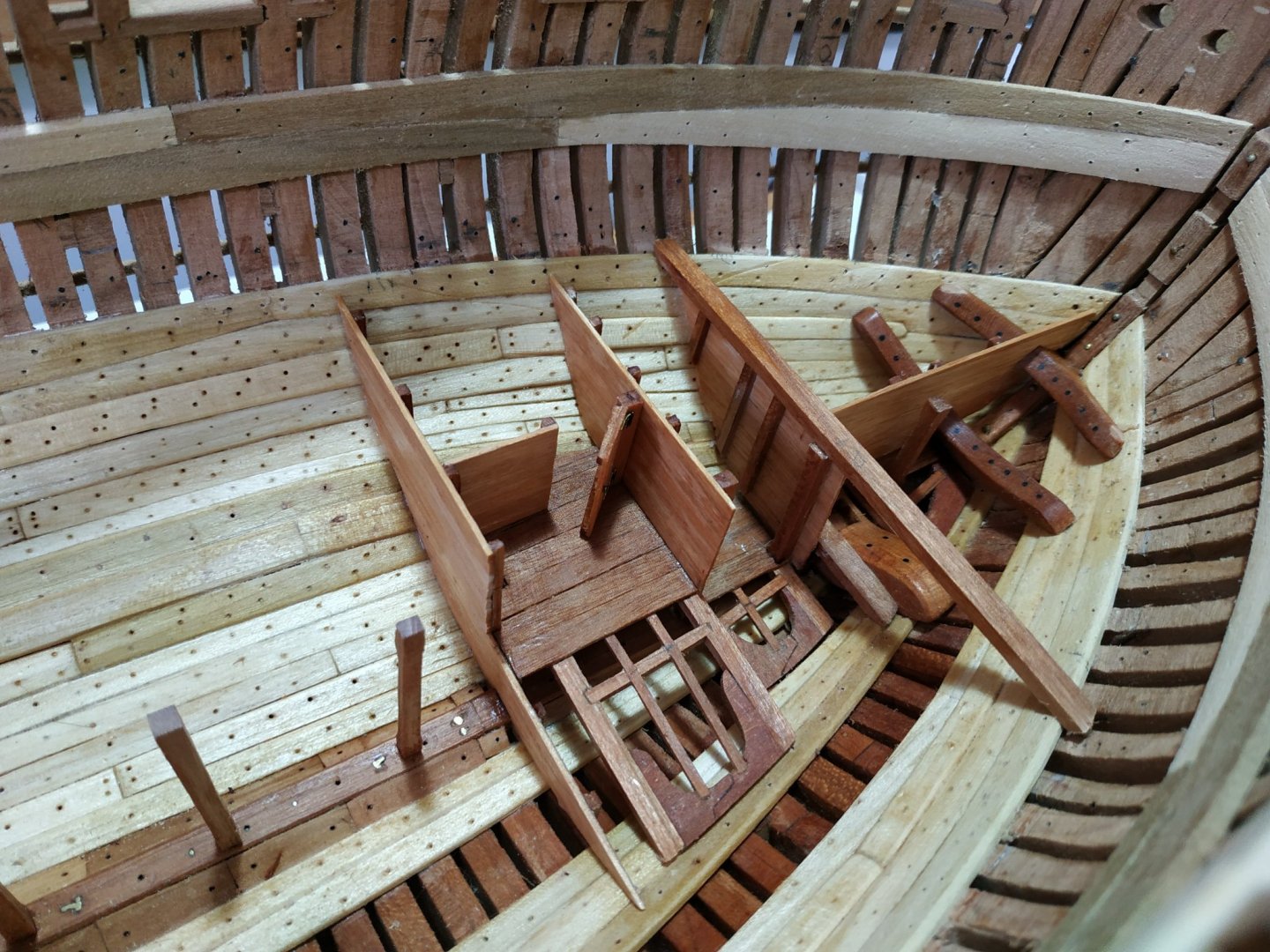

-
Swan-Class Sloop by Stuglo - FINISHED - 1:48
stuglo replied to stuglo's topic in - Build logs for subjects built 1751 - 1800
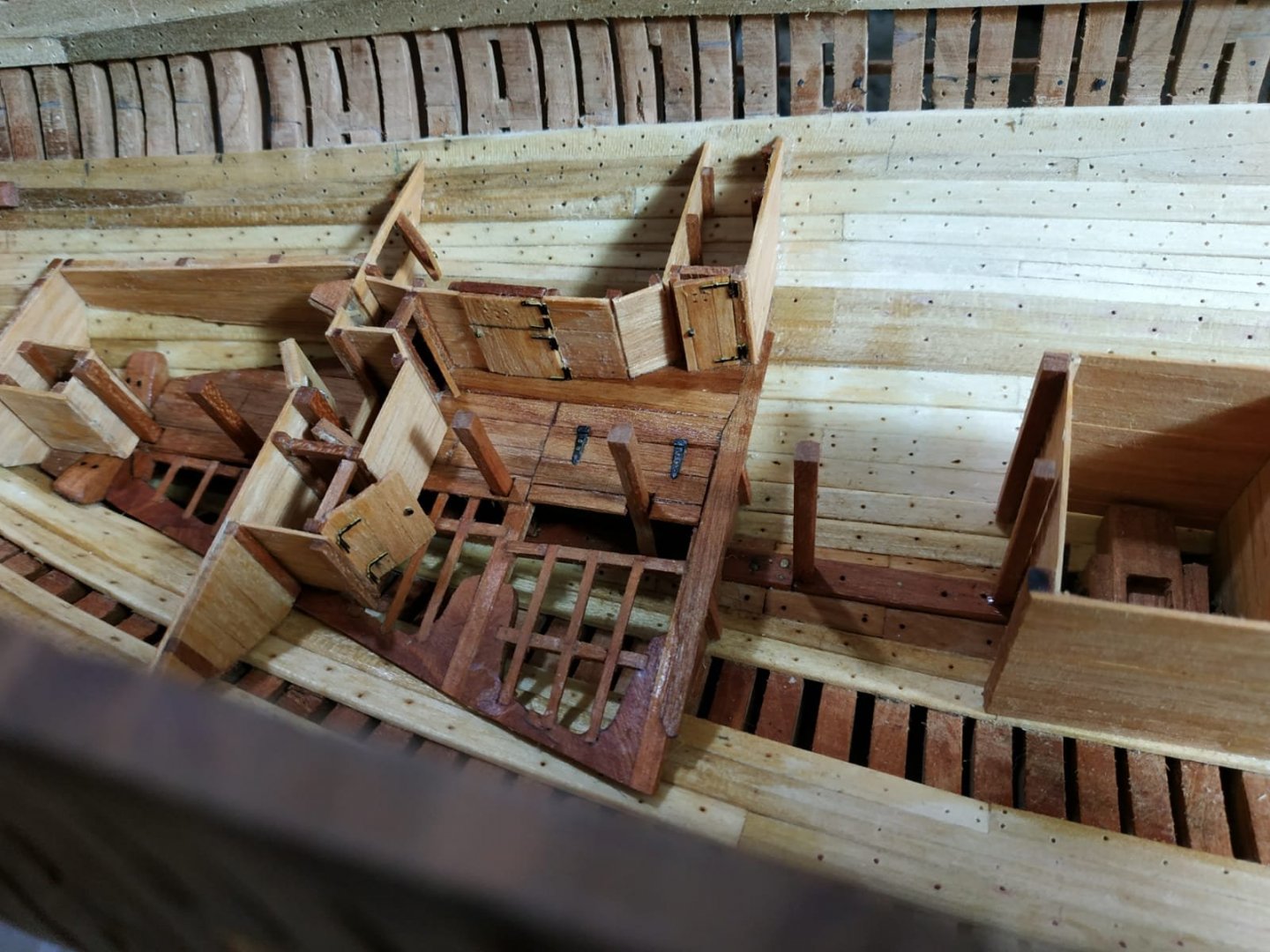
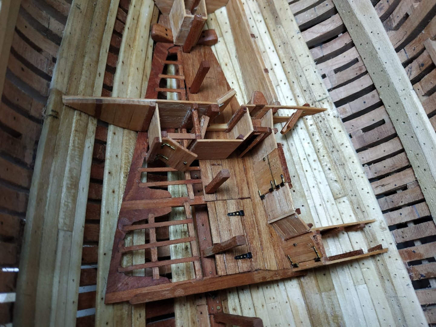
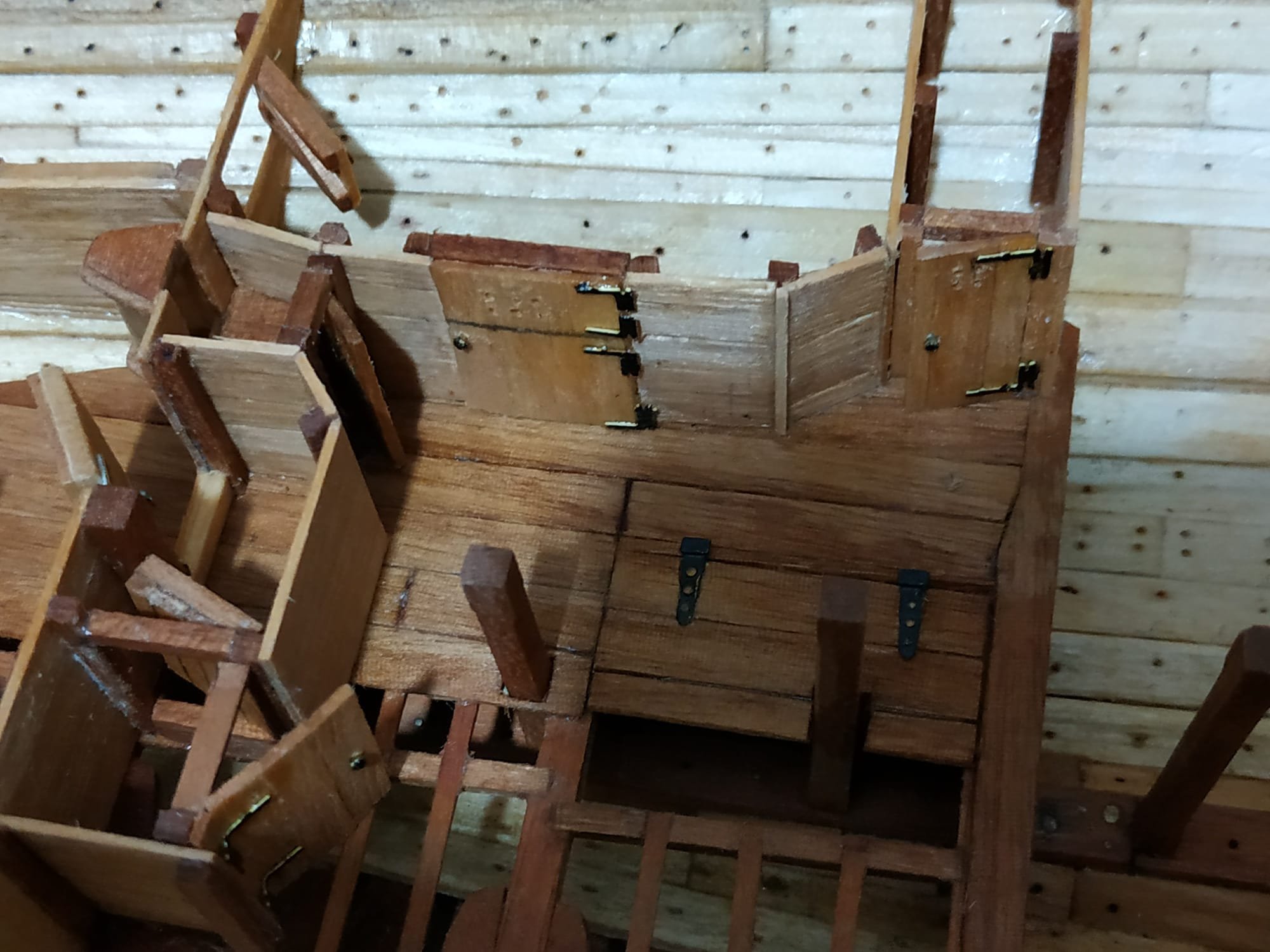
Passageway To Magazine Door Plank walls with stanchions. (no thick walls) Forms a dog leg. Height determined by underside of beam, and width according to plan in TFFM. Door sill again 3.71mm and I made a Zframe for a thicker door . Door and Light Room. Not all walls are parallel.I fitted doorways with lintels when not directly under beams. The shelf in light room needed removing to alter shape slightly to fit the angle of the wall. Door: narrow with vertical planking Stewards Room: foreward to bedroom on port side. Ensure height suitable for #15 beam (19.5mm at center) The Steward room door is relatively wide (15mm) and is split horizontally. It has 2 sets of L-shaped hinges. Forward of this is a narrow slops room with a simple door. These doors, we are told, can be made with a barred opening or simple holes. The former is too much at this scale and with cause me excessive frustration for what will be a hidden piece The Starboard rooms (Marines and Captains storerooms) apparently mirror the Steward’s and Slops rooms of the port side. These will be omitted.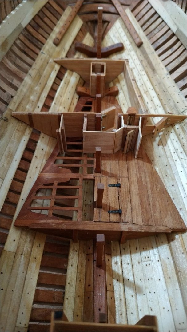

-
Swan-Class Sloop by Stuglo - FINISHED - 1:48
stuglo replied to stuglo's topic in - Build logs for subjects built 1751 - 1800
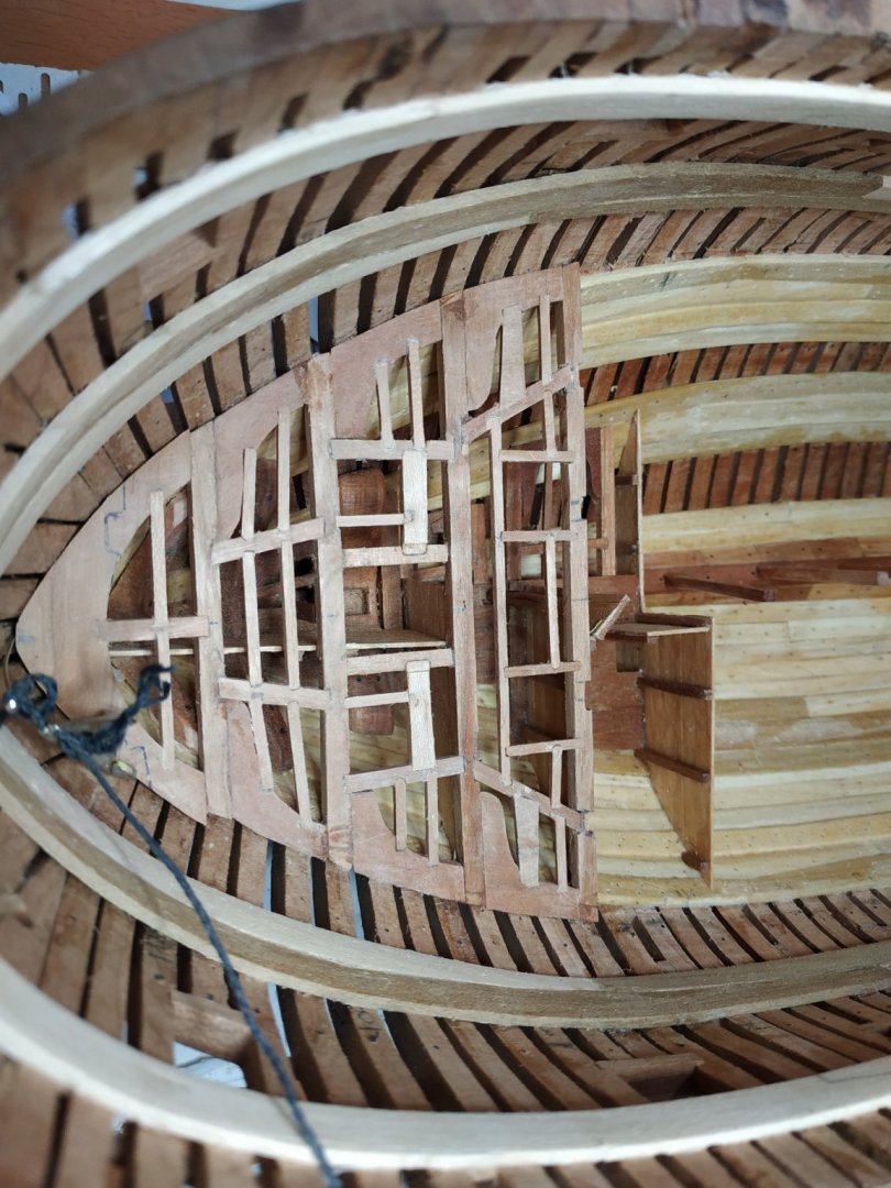
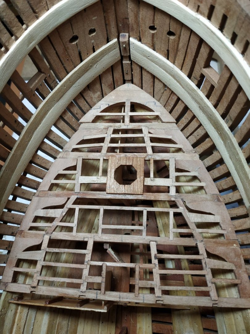
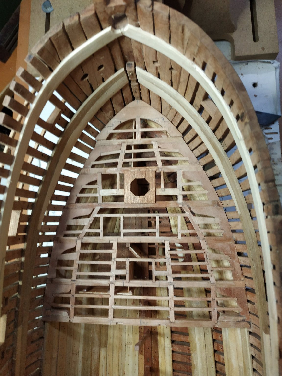
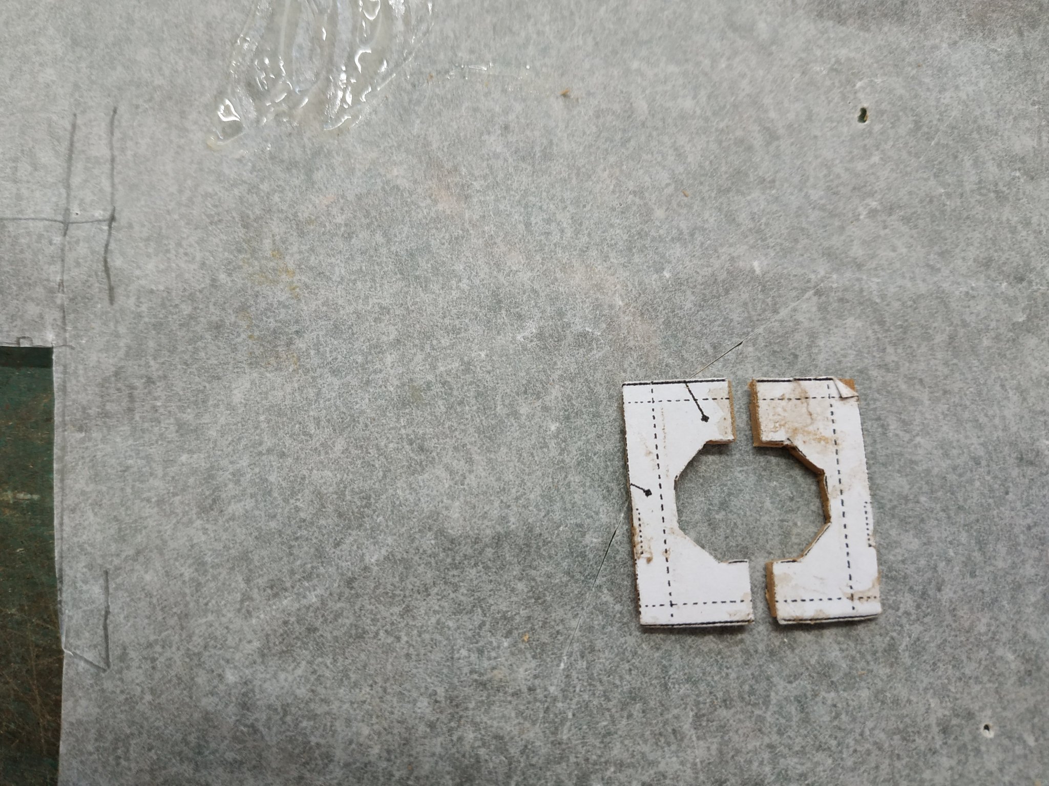
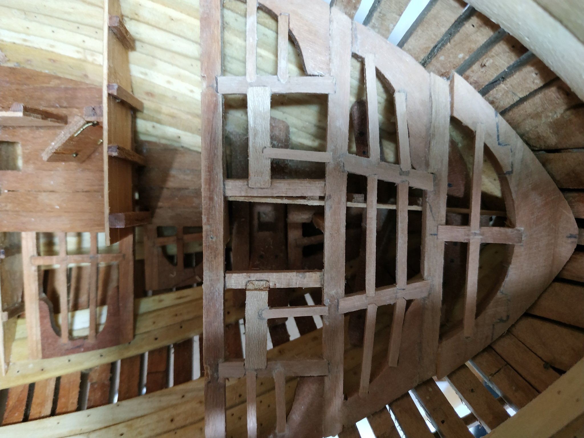
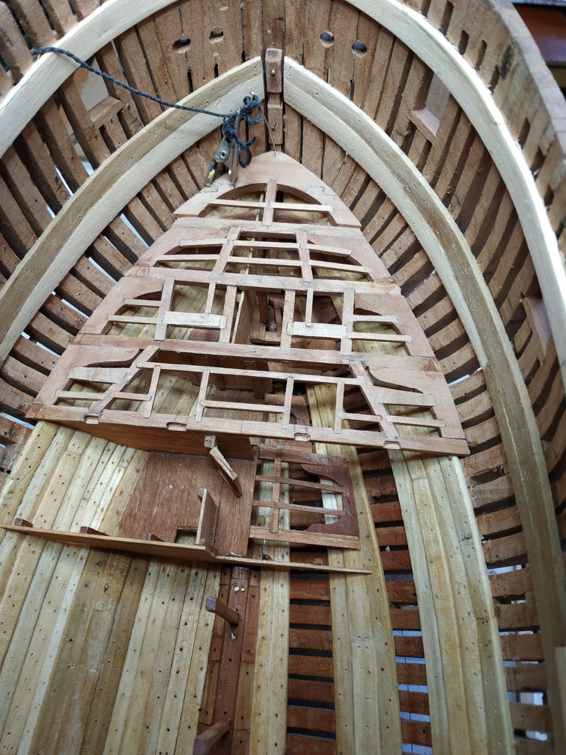
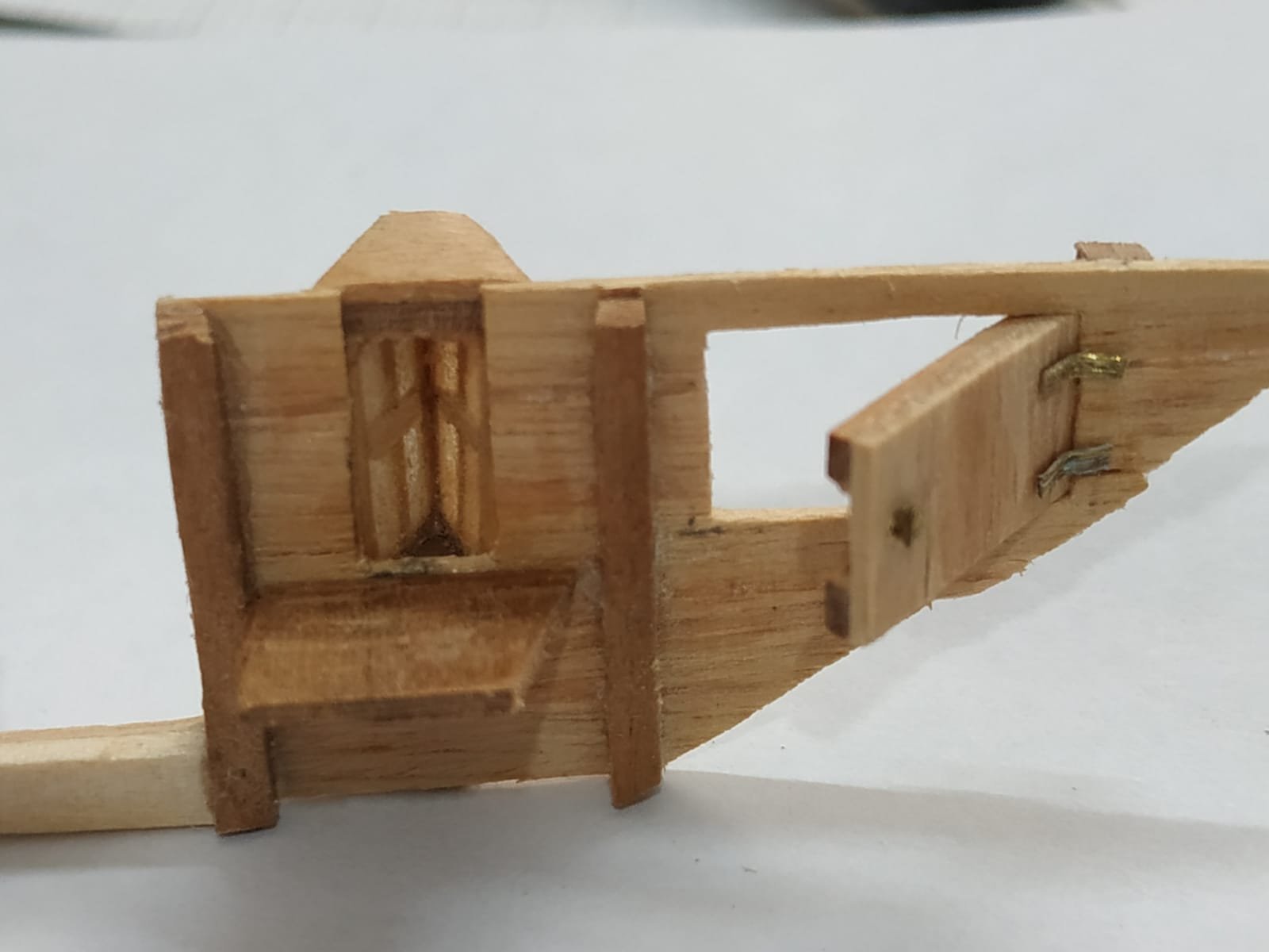
Magazine - fore bulkhead. (Somewhat complicated. Difficulty in understanding plan/plans as only part is shown on each. This is probably my deficiency, but again I used Vardas’s blogg for a clear picture.) This bulkhead is “anchored” to pillar #16 and due to its several components, separated the work into starboard and port sides. The starboard side is only partially “filled” with simulated mortar. The port side is very interesting. It includes a thick door (opening inwards) with a 3.7mm sill, a V-shaped window projecting into the magazine from the LIGHT room, and a horizontal door opening into the neighbouring bread room. This part of the bulkhead is made just with the planks and stanchions as shown. Leaving the sill, a doorway is made for entry to the magazine.The door, thickened, is hinged to the #16 pillar and the other doorpost is a stanchion.I think the sill would also be thick. Suggestion how to make a window in a TFFM appendix. The windows are only 11x6mm so I tried at first with some copper scraps. Not successful. (Little pieces and fat fingers!) Next some 1mm square boxwood-pva didn't “grab” Similar wood, now filled with a drop of epoxy and when dry, milled groove and fitted horizontal munion. Fair result. A V Shaped base was made and the windows glued to this with a batten covering the vertical join. A similar “roof” attached. Below the base is a 1mm wide wooden bracket. A corresponding gap, 5mm wide, is made in the bulkhead. A further hole is cut to fit a “horizontal” door to the bread room. Copper hinges and handle left as this was used in reality. The window is attached and a corresponding shelf forward into the passage (not yet built). The bread room door has a Z-shaped frame and is fitted to open forward. The thick magazine door is fitted and the port side bulkhead assembly attached so that the sill abutts to the #16 pillar , continuing the line of the starboard side. The portside magazine wall needs adjusting and perhaps would have better be made now rather than earlier. Some additions (cheating) to its base is necessary, as when realigned to its proper place on the bulkhead, its height needs increasing. A complicated and fiddly build, but ultimately satisfying and worthwhile even though it will be hidden.


-
Swan-Class Sloop by Stuglo - FINISHED - 1:48
stuglo replied to stuglo's topic in - Build logs for subjects built 1751 - 1800
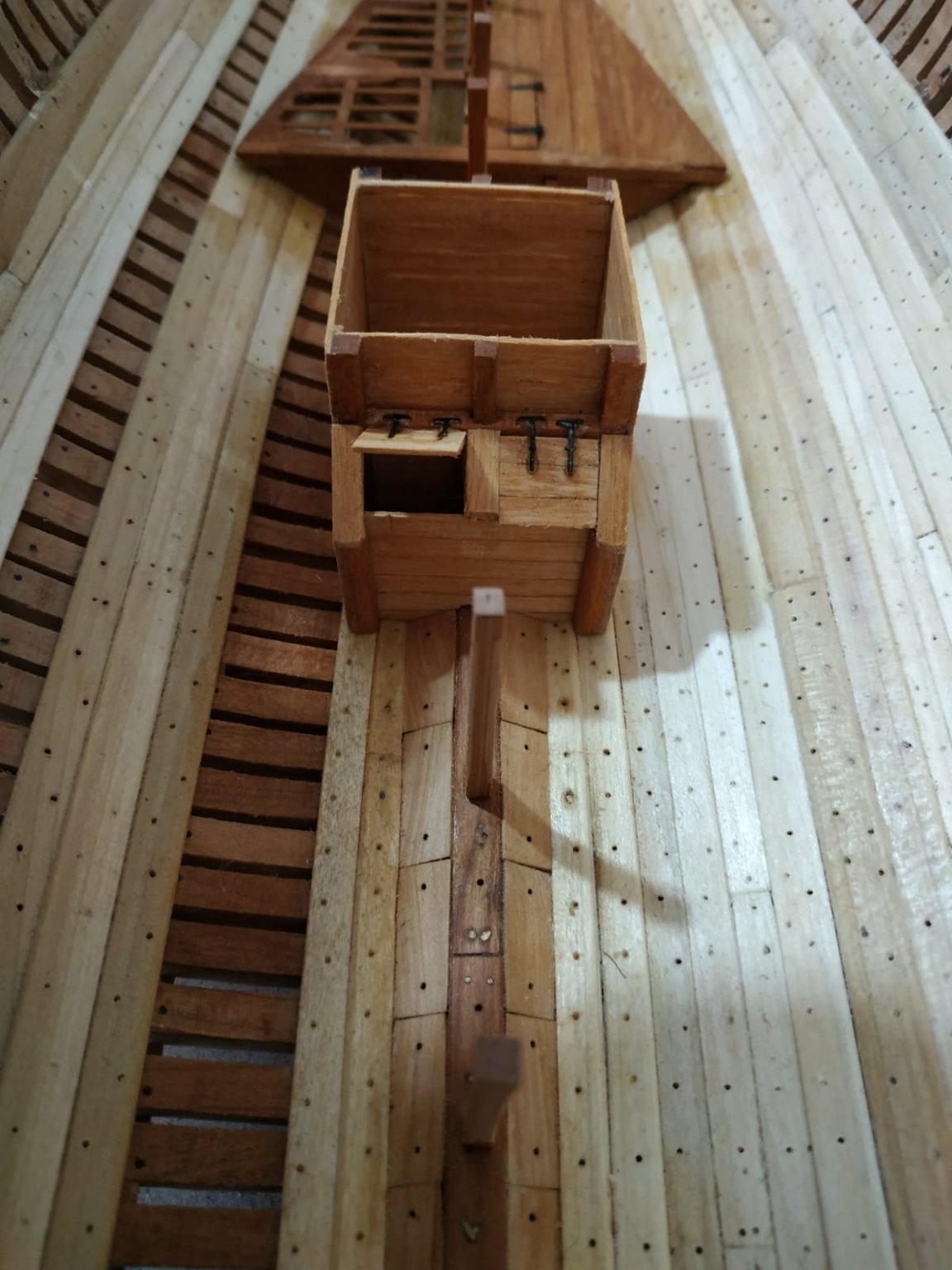
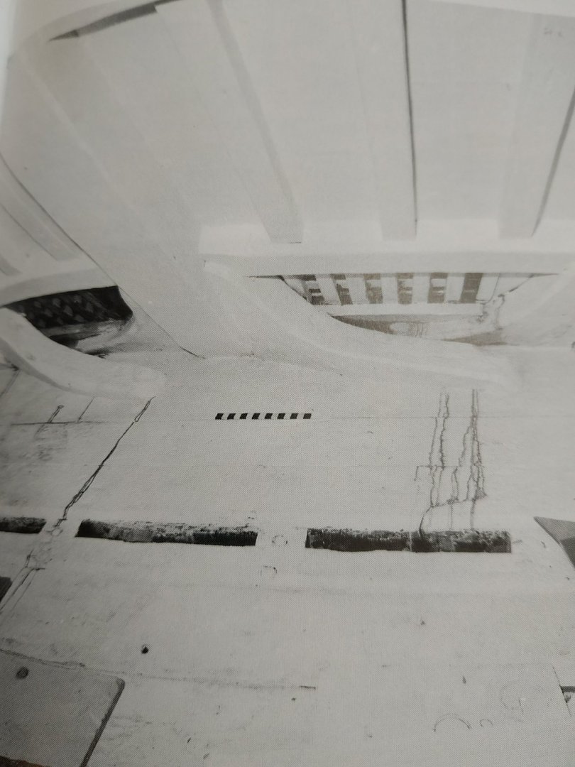
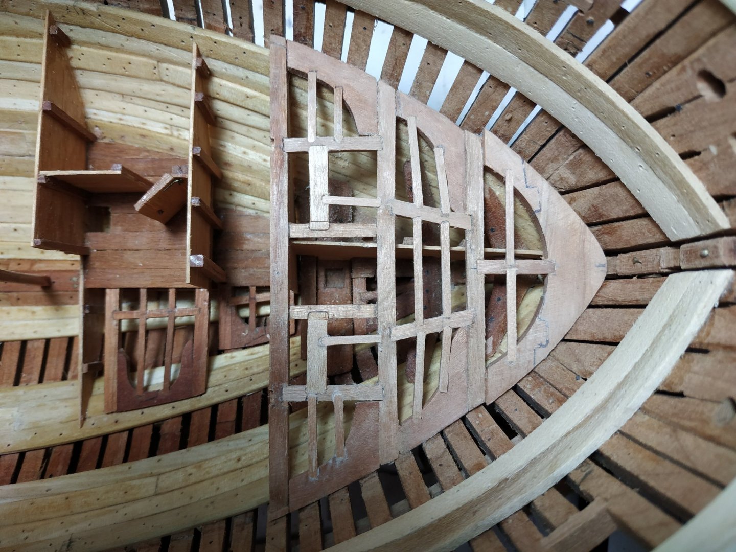
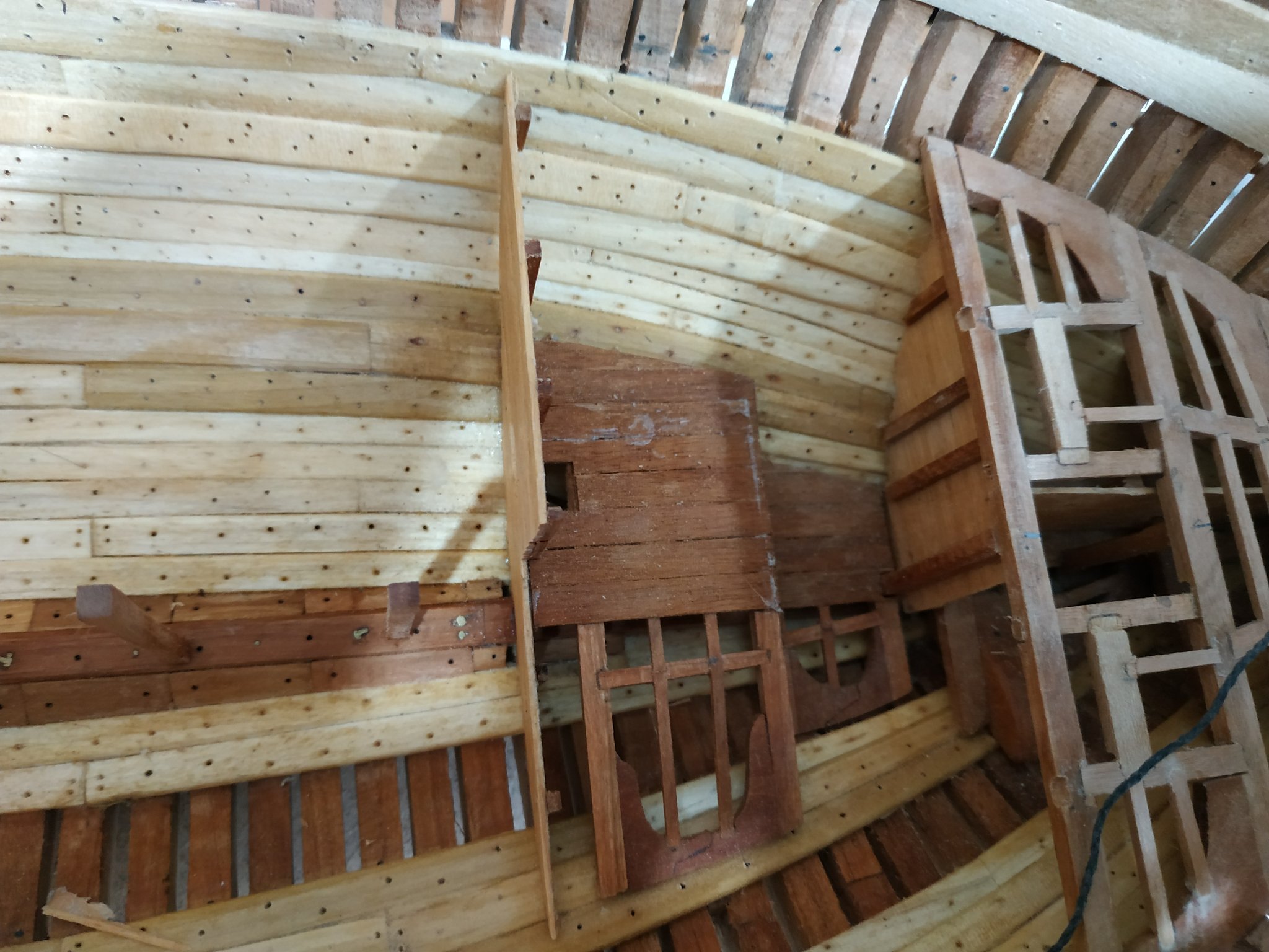
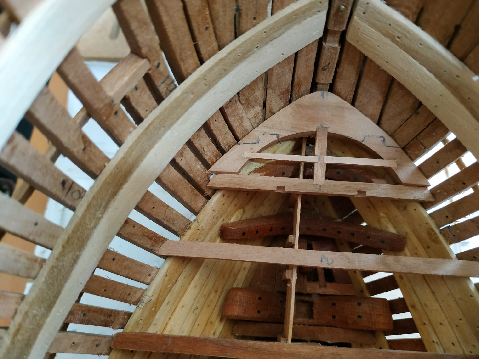
Decision: Despite not visible, will attempt the various rooms and structures in the hold. Magazine and Filling room. A series of bulkheads, passages and doors form this and other rooms. I have no separate plan for this so will go with the patterns in TFFM. Also Dan Vardas’ blog considerably helps understanding. The stanchions are 2.12mm square. ( The bulkhead planks join to hold ceilings via battens 2.12x1.06mm-which I have omitted. ) Starting with the aftermost bulkhead. It sits under #19 lower deck beam. The beam pillar, unlike those foreward, extends to support the upper deck beam. The lower deck beam is slightly mortised into this. The bulkhead does not extend all across to port side, rathervis “squared off” A pattern is made for the lower edge (trial and error) and the horizontal planks glued to this and the shaped, ensuring the upper edge fits under the beam. This is glued to the fore side of the pillar #19. They can be removed together as the pillar is attached by a brass pin into the keelson. The stanchions are added per plan. The walls are extra thick, as the spaces between the stanchions are filled by mortar. I represented this by some vertical lime strips 1.38mm thick. ( I decided before the build that I did not want to use paint if possible) The bulwark can be fitted by positioning the pillar on the pin. Mizzen mast Sleeve Tried by “prefabing” walls. Plan does not show an aft wall, but I put one in for stability. Corners chamfered.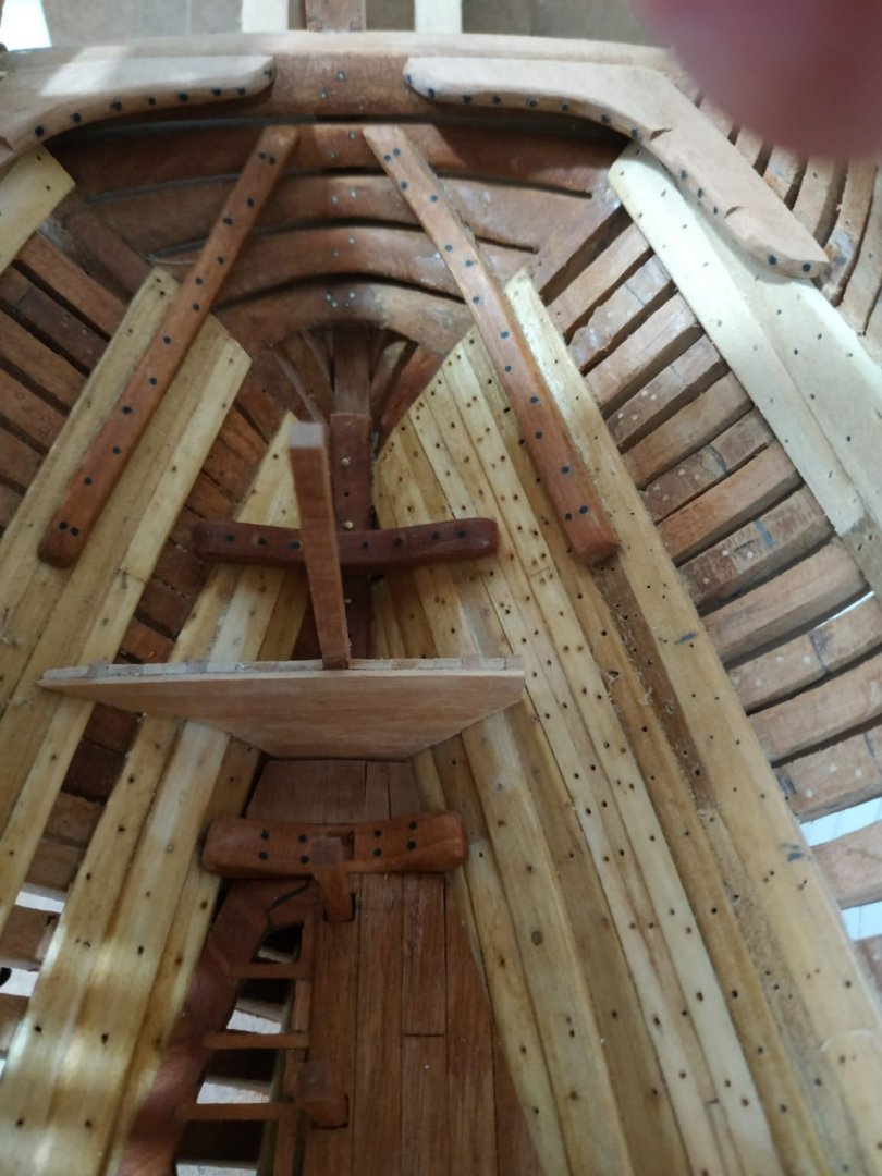
.thumb.jpg.14757147a2a5ac986964a79e2f0efb3b.jpg)
-
Swan-Class Sloop by Stuglo - FINISHED - 1:48
stuglo replied to stuglo's topic in - Build logs for subjects built 1751 - 1800
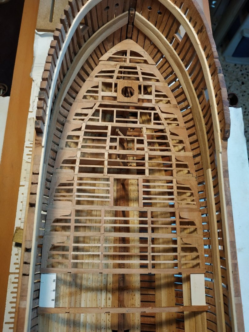
FORE PLATFORMS Built in 4 sections. Referring to the Atalanta profile plan, some variance to TFFM.The bulkheads seem to ve (vertically)continuous and limit the planking. Somehow, more confusing than their aft counterparts- the importance of previously fitting the lower deck pillars (as suggested by FTTM) becomes obvious. The aftmost (4th) and 2nd platforms sit about 6.36mm higher than the 3rd. Locating the aftmost beam 28.5mm aft of 4th pillar (allowing 1mm bulkhead). This aftermost beam mortises into the Bitt uprights. The cross beams are 3.64x2.65, carlings and ledges also as before(3.16x1.6,1.6x1.0) As usual, paper copy with mirror image, glue to blank, cut out and shape. Recessed for pillars 4+5 The higher parts are angled slightly upwards going foreward. The lowest section appears horizontal about 2.5mm above keelson. The 2nd section is a narrow part, slightly wider than its beam. The profile plan shows some connection with the first part, but I can't see how with the height of the foremast step. The foremost section is the same height as the 2nd,it extends under the breast hook. PLANKING Extends aft of 4th, to include the Bitt upright and abutts to bulkhead. Sited as such, the gap in the limberboards is incorrect and needs moving forward by 5mm. (PVA dissolved and boards recut and moved). As TFFM says, go with the plan you have!!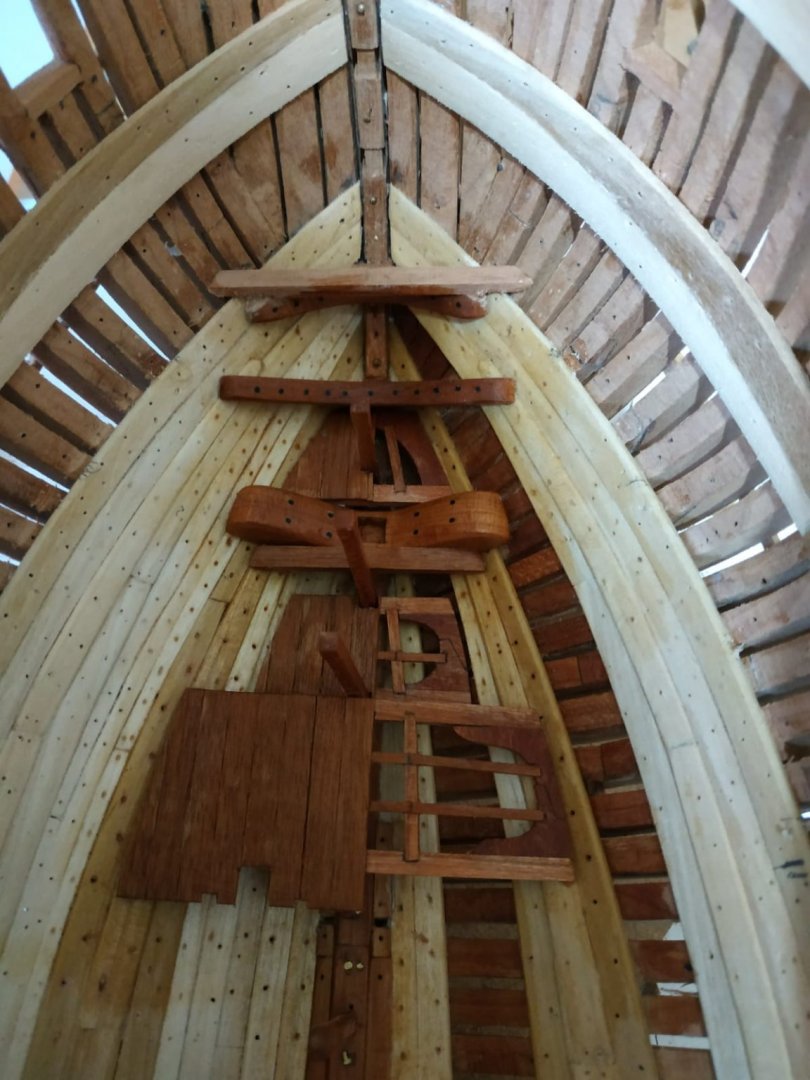

-
Swan-Class Sloop by Stuglo - FINISHED - 1:48
stuglo replied to stuglo's topic in - Build logs for subjects built 1751 - 1800
I think its tanganyka, planks from a kit at least 20 years old. It "mottling" remains after sanding and oiling- not present when originally used. Maybe the weathered look will grow on me. I wanted a contrast-to be seen in unlit hold. I suppose walls and bulkheads were painted whitish so as to be seeb in the gloom of below decks. -
Swan-Class Sloop by Stuglo - FINISHED - 1:48
stuglo replied to stuglo's topic in - Build logs for subjects built 1751 - 1800
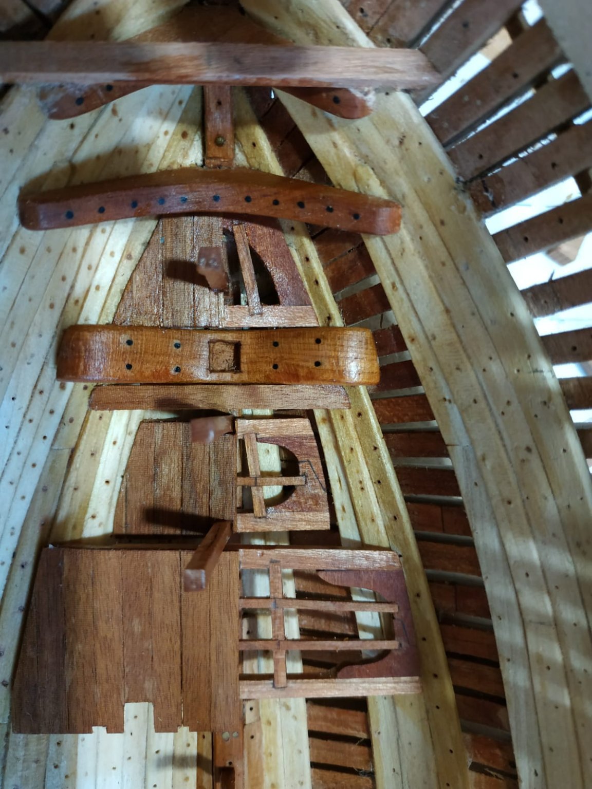
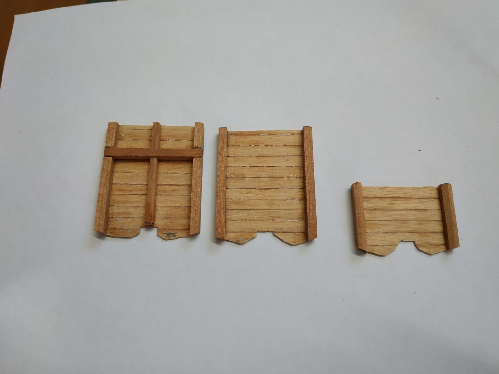
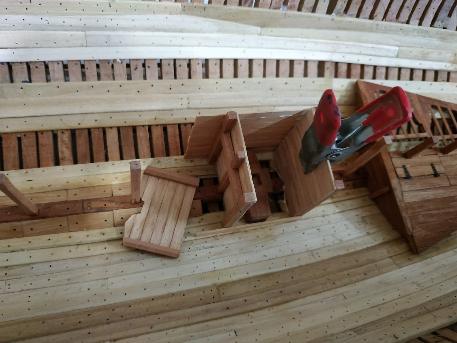
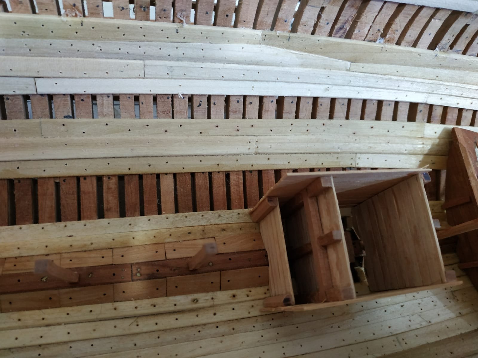
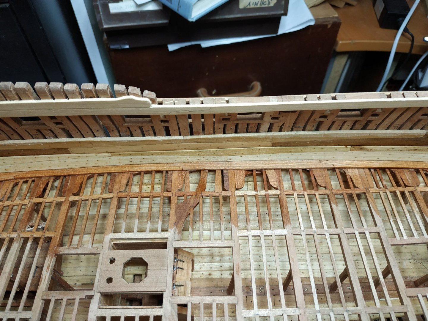
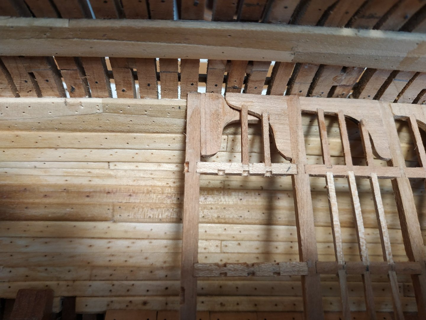
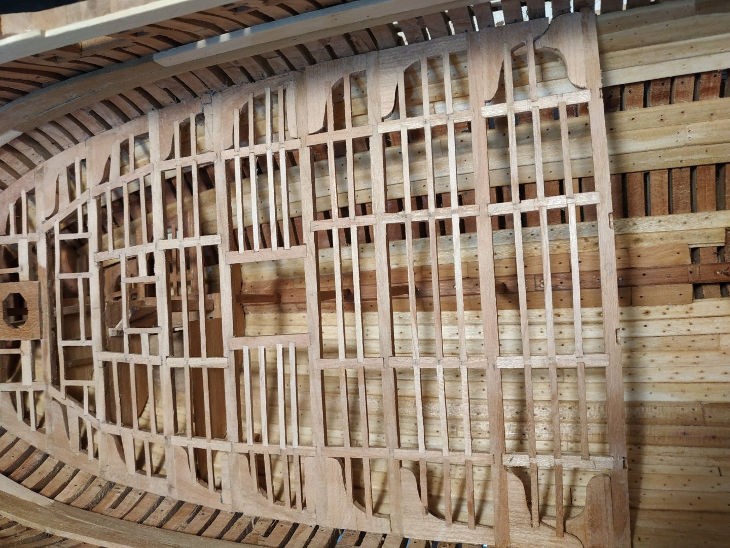
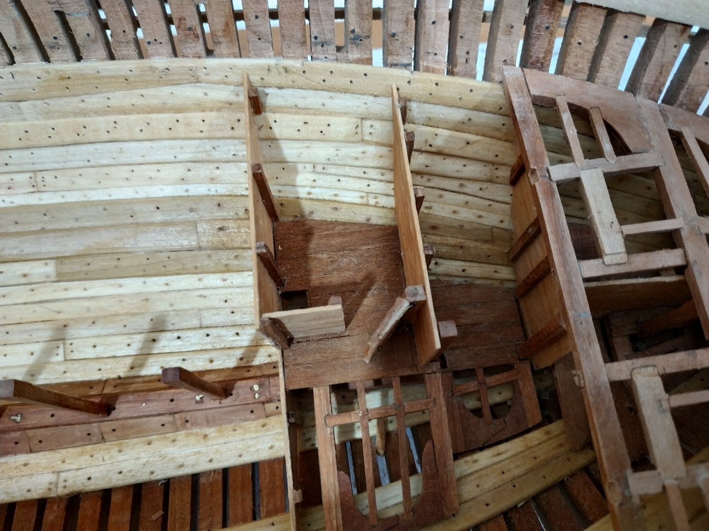
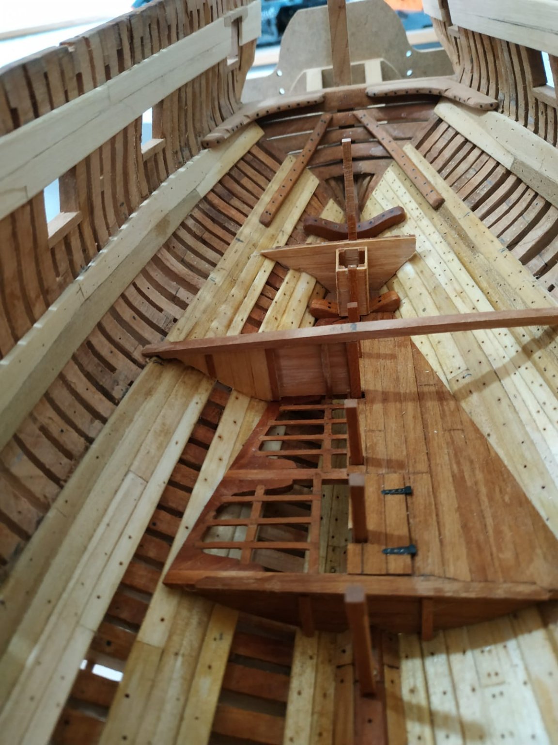
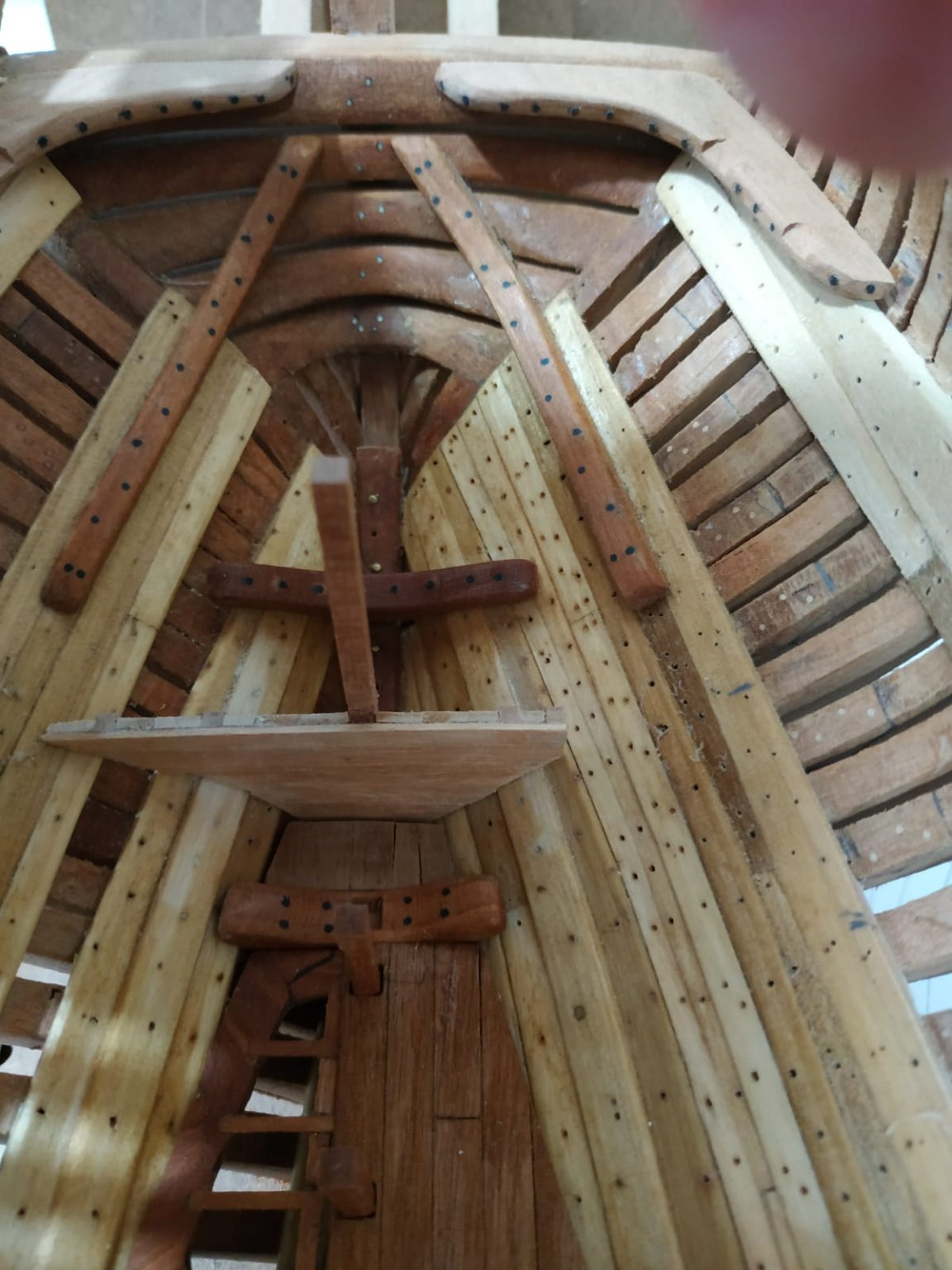
THE WELL and SHOT LOCKERS. These are compartments in the hold. Dimensions given are 35mm sq for the former, and the latter, same width and 11.13mm long. The rear bulkhead sits under the aft aspect of beam#12 . The height is that of the underside or the lower deck beam. The fore bulkhead of the locker is 24mm, the sides continuous with the well, slope down from the bulkhead shared with the well. At the bulkhead corners are stanchions, 3.18mm sq. The pillars #11 and #12 between them on their respective bulkheads. Foremost, are stanchions at the corners of the locker that have a 45deg bevel. Additionally there is a similarly sized cross beam marking the height of the locker. **I think the main problem is deciding the order of build. ** As the pillars already in place determine the position and dimensions, I decided to build the bulkheads first. Also the bulkhead can be easily held in position while measuring and making the walls. Therefore paper templates made, overlaid with the planks (I again used some ready made if undersized wood-only 4.55x1mm) Stanchions glued to aft side and temporarily clamped to pillar #12. (Gratifying to see bulkhead match the gap in the limber boards) The middle bulkhead was similarly made, but as the horizontal beam needed mortising into all 3 stanchions i.e.including the pillar#11, I freed up the latter from its holding pin in the keelson, and milled the required motises. This proved very useful, as I could now replace and firmly fit the parts as the build required. With these bulkheads implace, I planked the sides with forward extensions for the locker. When dried, removed as whole, heights of sides corrected, and using the cross beam as a guide, shaped the locker side and fore bulkhead. Inside the locker is a dividing wall, running starboard side of pillar#11 and the fore bulkhead, where a suitably short stanchion adds support. A pair of lids fit either side of a piece of planking which covers the aforementioned locker partition. Similar planks cover the tops of the walls, rather like bannisters. A very satisfying build, particularly the order saved a lot of fiddling about. Choice of wood for planks was probably a mistake, but will be mostly hidden from view.


.jpg.63e4bbca85cc1f67ef6306b61aca38ac.jpg)