stuglo
-
Posts
707 -
Joined
-
Last visited
Content Type
Profiles
Forums
Gallery
Events
Everything posted by stuglo
-
Swan-Class Sloop by Stuglo - FINISHED - 1:48
stuglo replied to stuglo's topic in - Build logs for subjects built 1751 - 1800
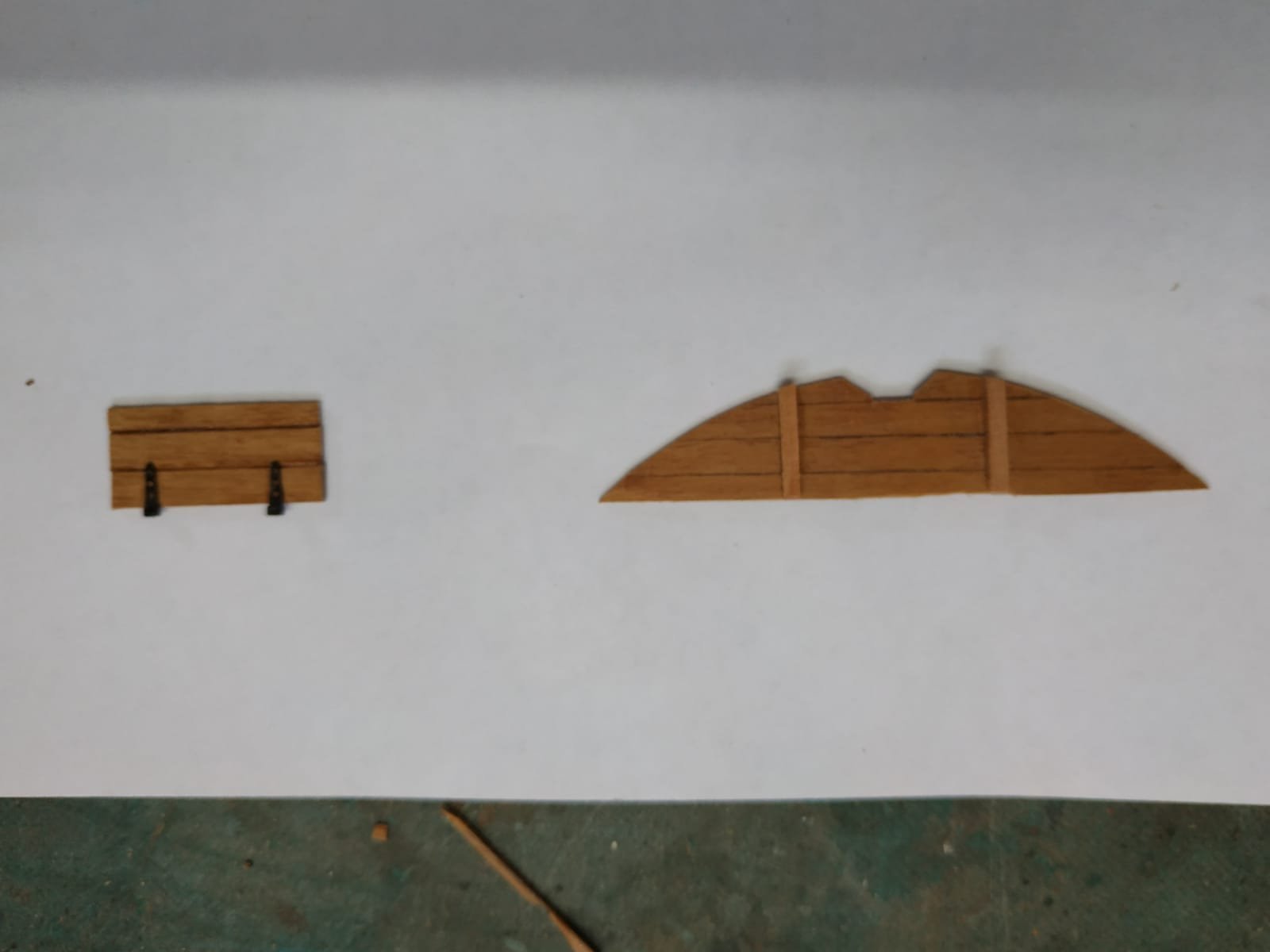
Fishroom Bulkhead Fits under forebeam of aft platform, HORIZONTAL planks 1mmX4.77wide. Made a paper plan, simply by trial and error ie. snip and fit. (my pin shape is too wide) The bulkhead is braced by a pair of stanchions 2.12 mm sq. To be fitted after the platform is finished and in place Aft Platform Planking. TFFM calls for planks 0.8mm thick and 6.36 wide. I have some walnut left over from kit at 5mm wide, so I decided to go with this.Hope this is not too unorthodox. The planking leaves a scuttle edge free at 1mm to allow for a rebated hatch. It also falls short on the fore beam to allow a lip-shaped lip extending over the beam for most of its length. This edge is rounded. I marked and cut out holes for the pillars. A half (port) lid was made with similar planking.A hole is also required in this for a pillar. Hinges also left over from another kit. Decided against fastenings (this time not treenails) as probably almost invisible. Fitted, glued and bulkhead added when set, Finished with tung oil.

-
Swan-Class Sloop by Stuglo - FINISHED - 1:48
stuglo replied to stuglo's topic in - Build logs for subjects built 1751 - 1800
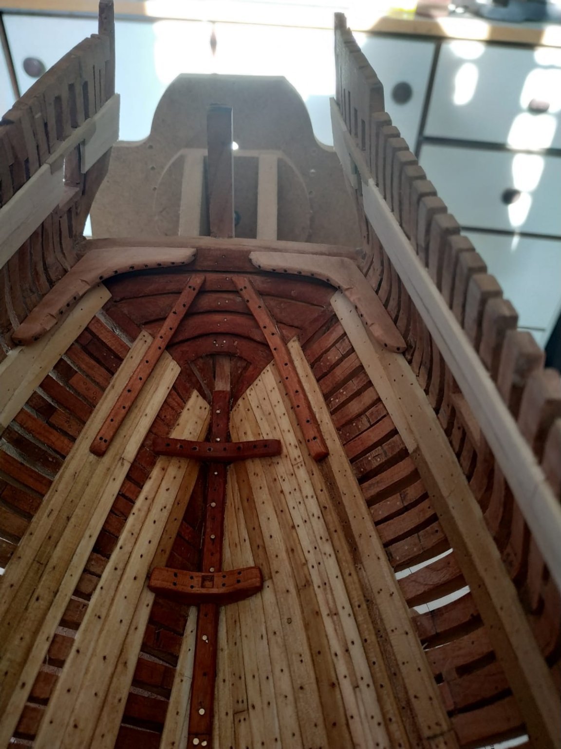
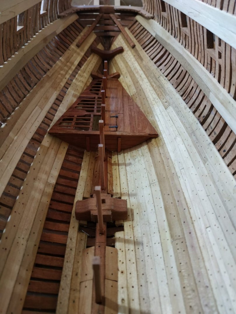
SUPPORT PILLARS for Lower deck beams Details from TFFM and profile plan Atalanta Most centred under beam and note relationship to structures of platforms and bulwarks. The position of a few beams slightly altered. Also allowance for slope of keelson upon which the pillars stand. **One of the advantages in writing this blog is that although the rough copy is produced while working on the model, this published version is after completing each stage. Therefore, although I note that the pillars are generally 3.2mm square, nos. 11 and 12 are 2.65mm sq. THIS I FORGOT. So removal and alteration required.** Tenons are mentioned at bases, treenails given as an alternative. I used brass pins , removing the head, and CA glue. Using a small version of the measuring device, heights measured, appropriate shapins of base into which the pin inserted into a predrilled hole. The corners, except those abutting bulworks, are chamfered from 4.24mm above base to 3.20mm below beam. A simple jig helped this. The 5 pillars fore and 5aft have a tapered chamfer. Pillars 19+20 are extra long and will be left ‘til later. Note also that no pillars are shown beneath beams #1 and #5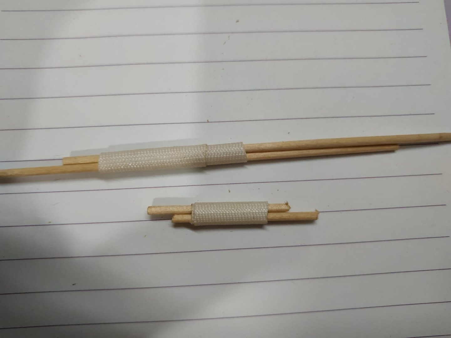

-
Fascinating. The "straight underside" is interesting. Saving cost (work hours) vs extra weight .Thanks everyone. Perhaps there was a variety depending on age, size and use.
-
Re. "tipping device" to angle ( ?Proxxon ) vice. Did you make or purchase it? (If so, where.) Your work is stupendous
- 589 replies
-
- 1
-

-
- le gros ventre
- cargo
- (and 1 more)
-
I'm sorry but I have failed to understand this thread. Is the round up the same irrespective of beam length- if not would so it will be be greater for a shorter beam if curve is an ellipse? For the model this may be irrelevant, but nice to know.
-
Swan-Class Sloop by Stuglo - FINISHED - 1:48
stuglo replied to stuglo's topic in - Build logs for subjects built 1751 - 1800
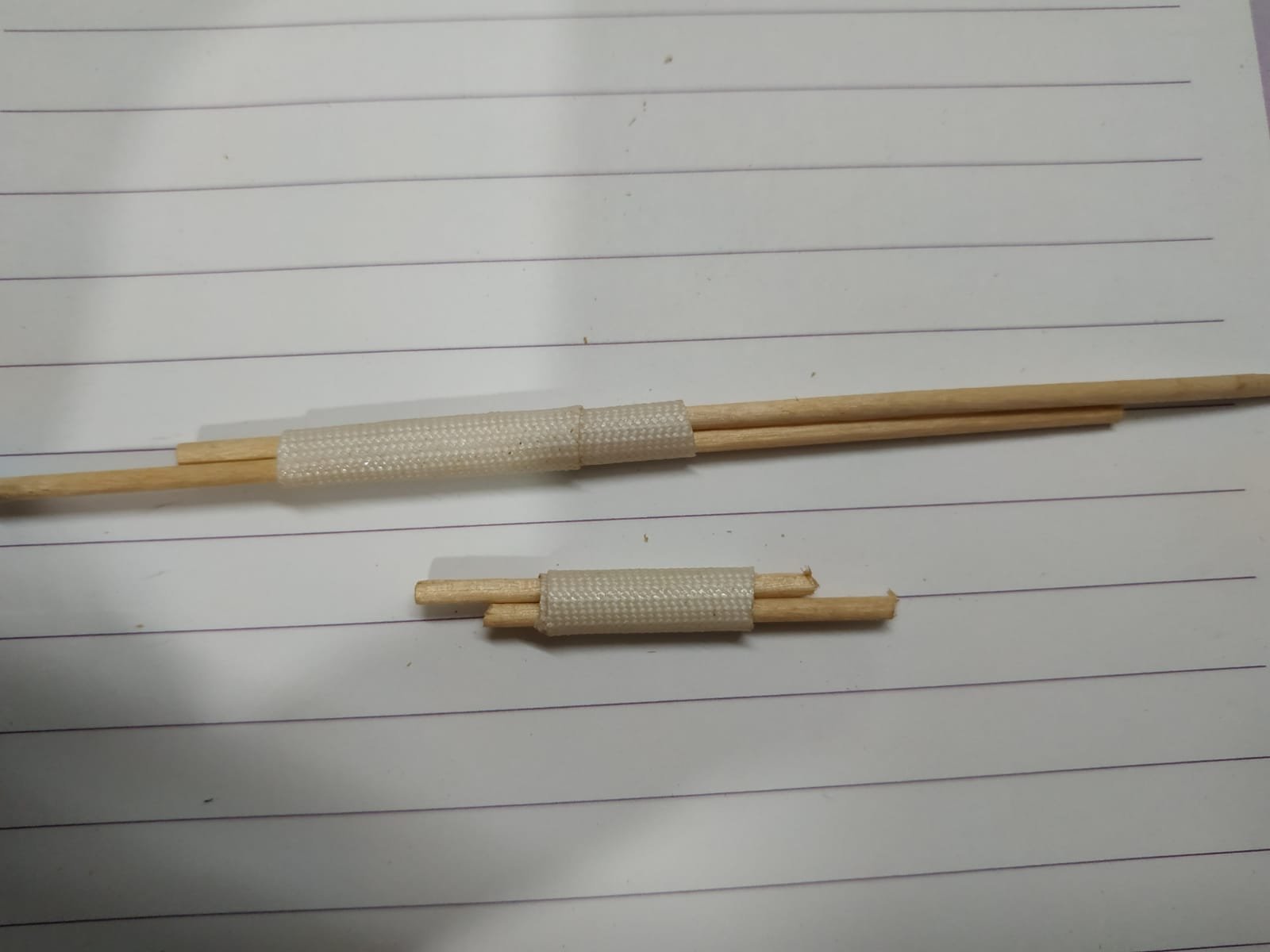
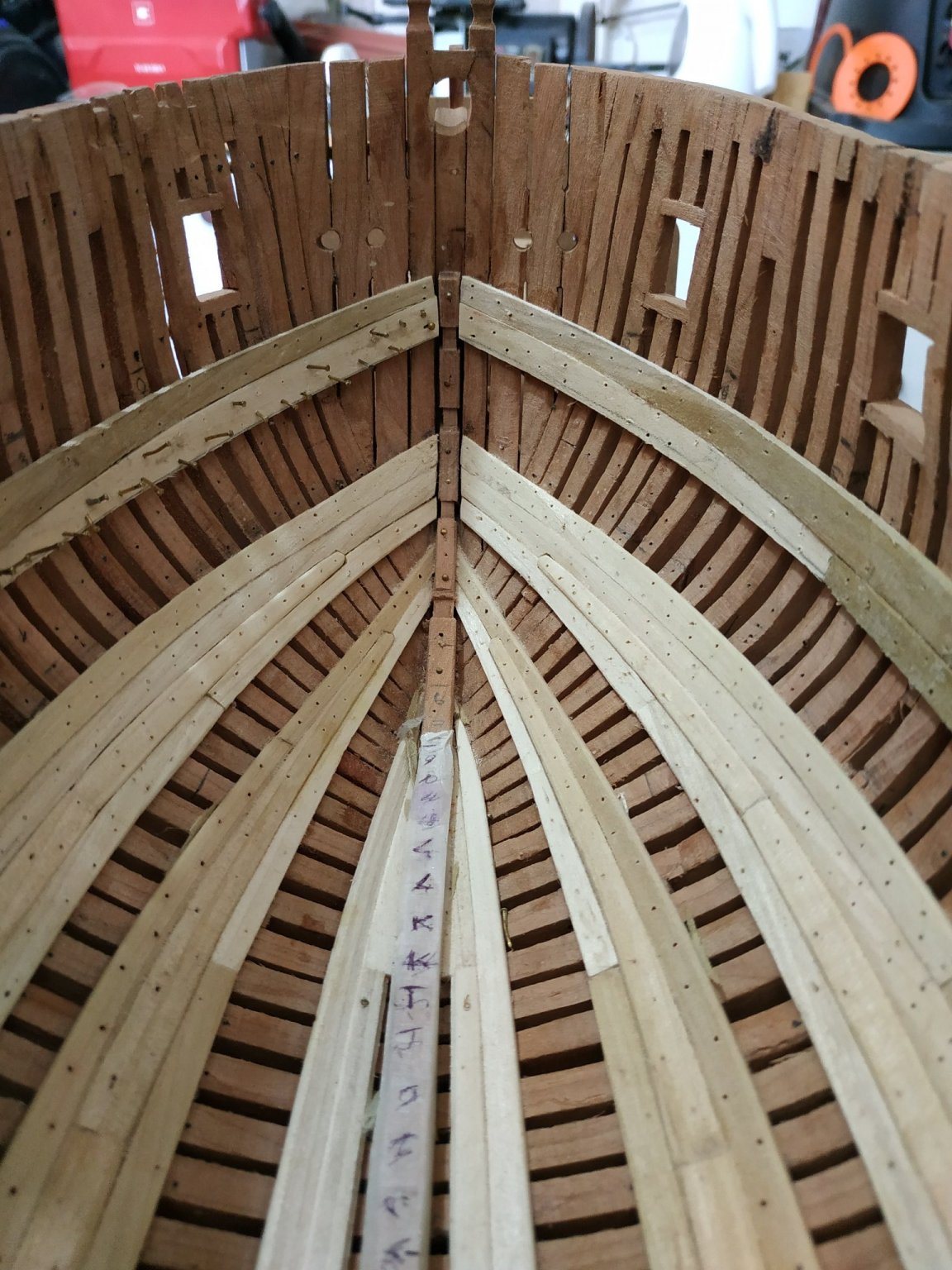
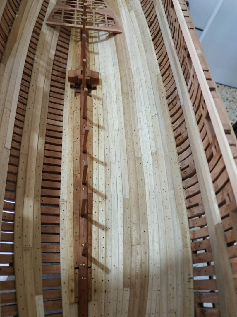
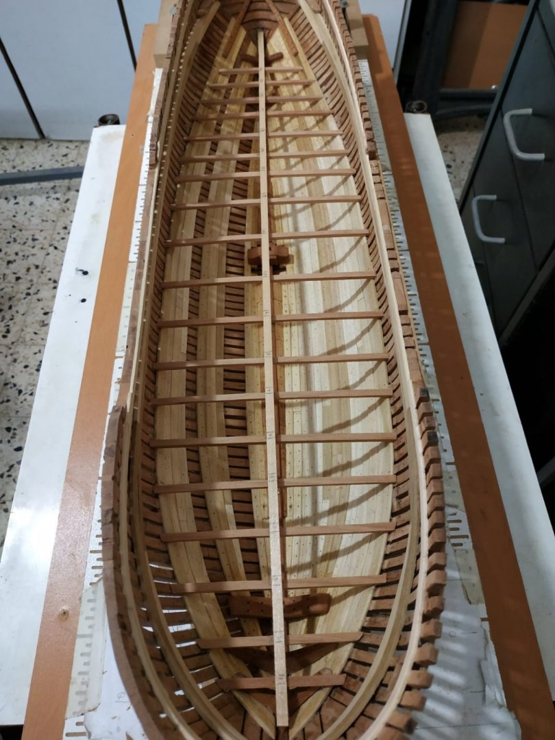
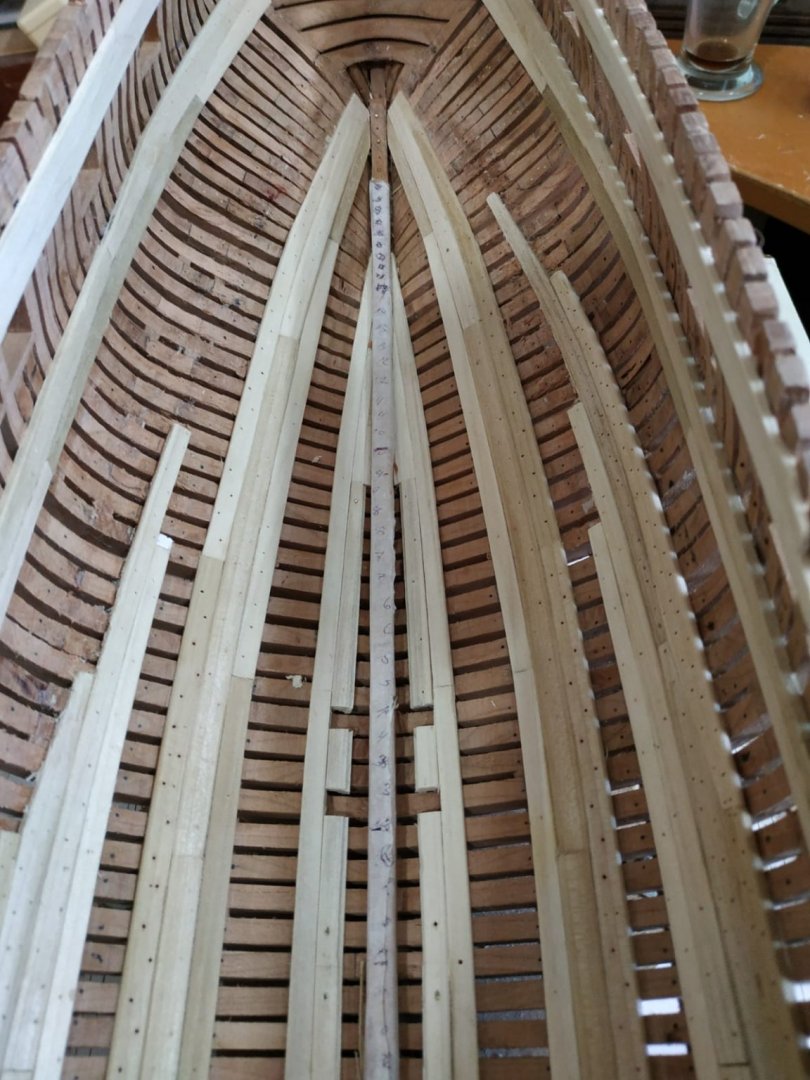
Lower Deck Beams (cont.) Their positions do not match exactly the stations on the plan and must be taken from the NMM plans. After measuring and comparison to the framing plan, these can be marked. After several hours, I checked out Kevin’s video blog, and saw a central strake,marked directly from the NMM plan, and overlying the beams, allowing a more accurate positioning. Recommended to start with beams #11 and #12( overling the well) A simple measuring device is described in TFFM which I have simplified further ( fabric wire rapper and stick broken in half) Remembering the “let down”- I milled 0.53mm notches either end of the beam once it had been cut to size and fixed (temporarily) with rubber cement. Height then checked with the depth gauge. Beams fore of the similarly made, with attention to shaping ends to match the curve of the clamp. The beams aft of #13 supposedly to rather than on the clamp (like platform beams) but #14 and #15 managed with a deeper notch.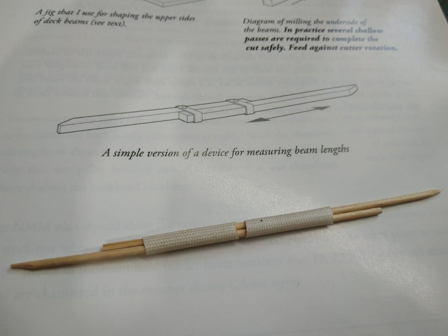
-
Swan-Class Sloop by Stuglo - FINISHED - 1:48
stuglo replied to stuglo's topic in - Build logs for subjects built 1751 - 1800
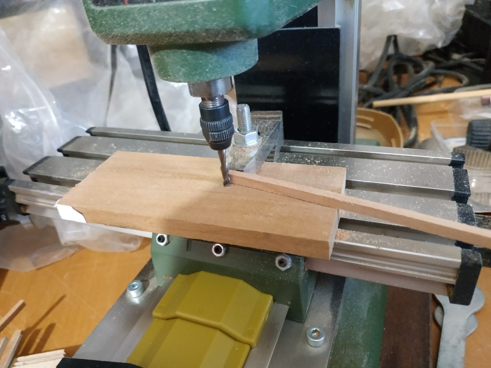
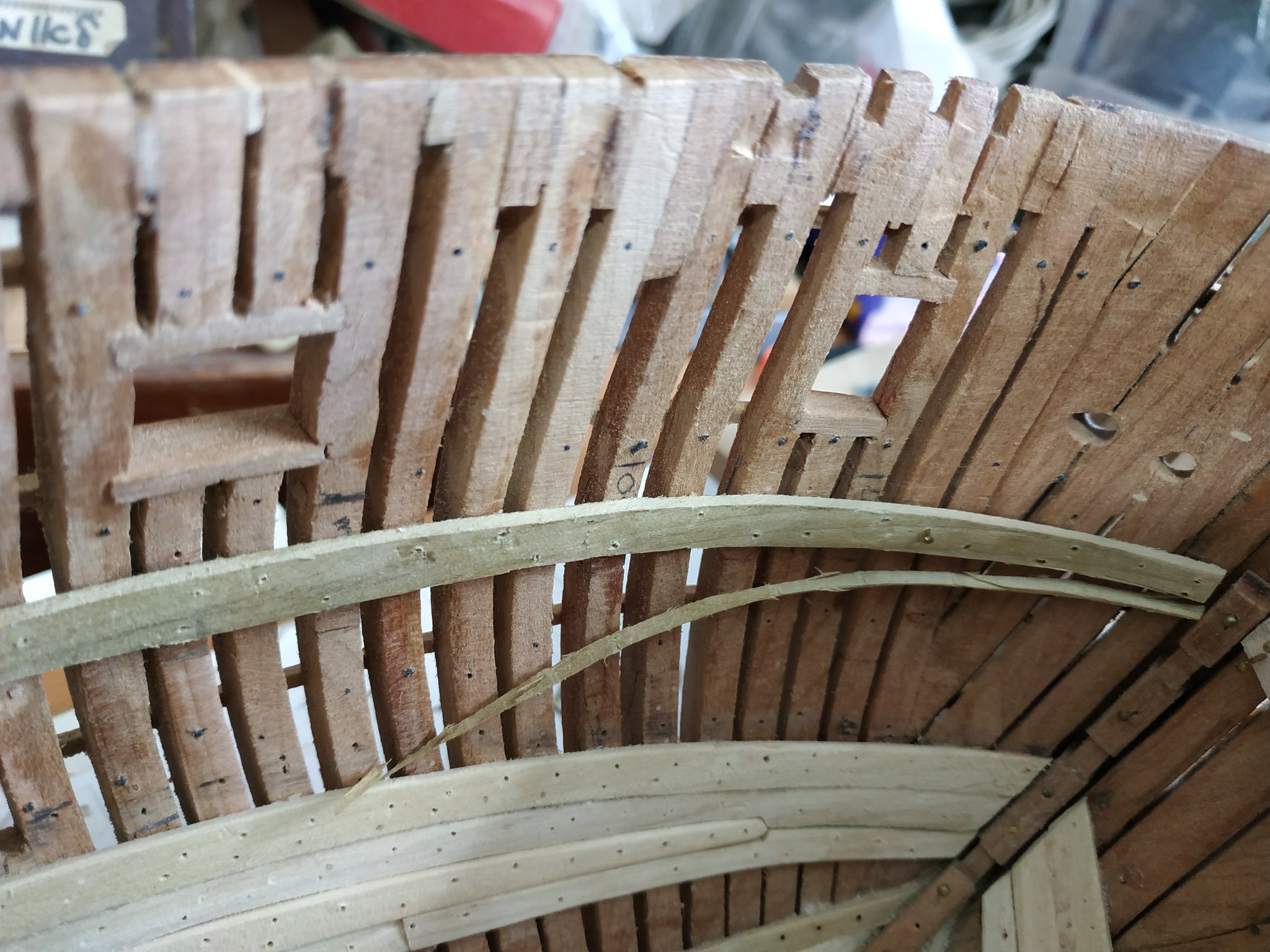
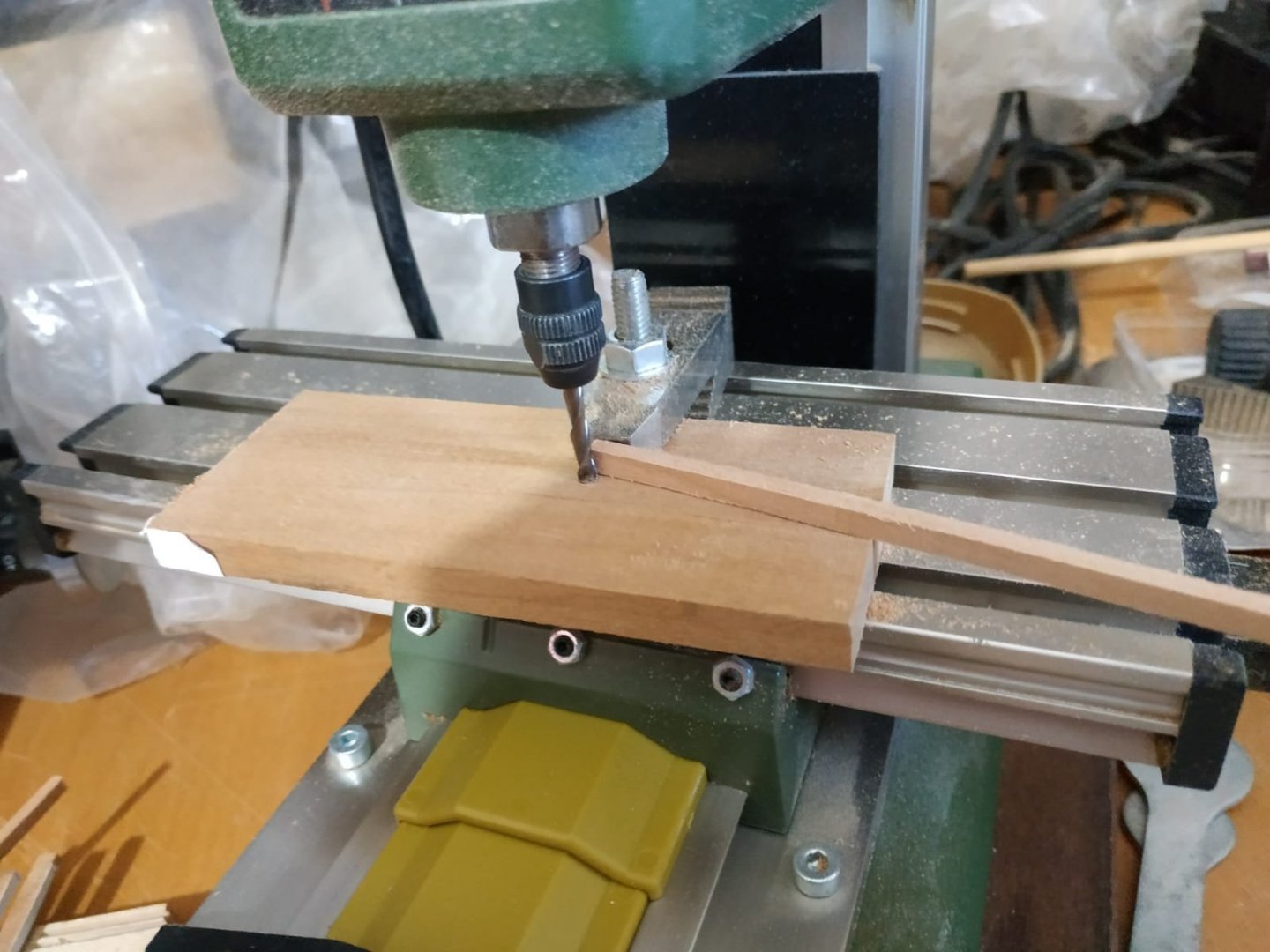
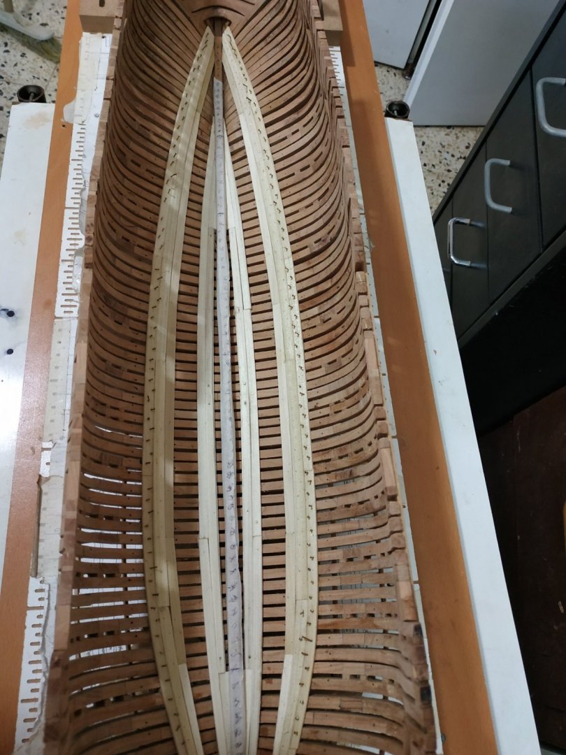
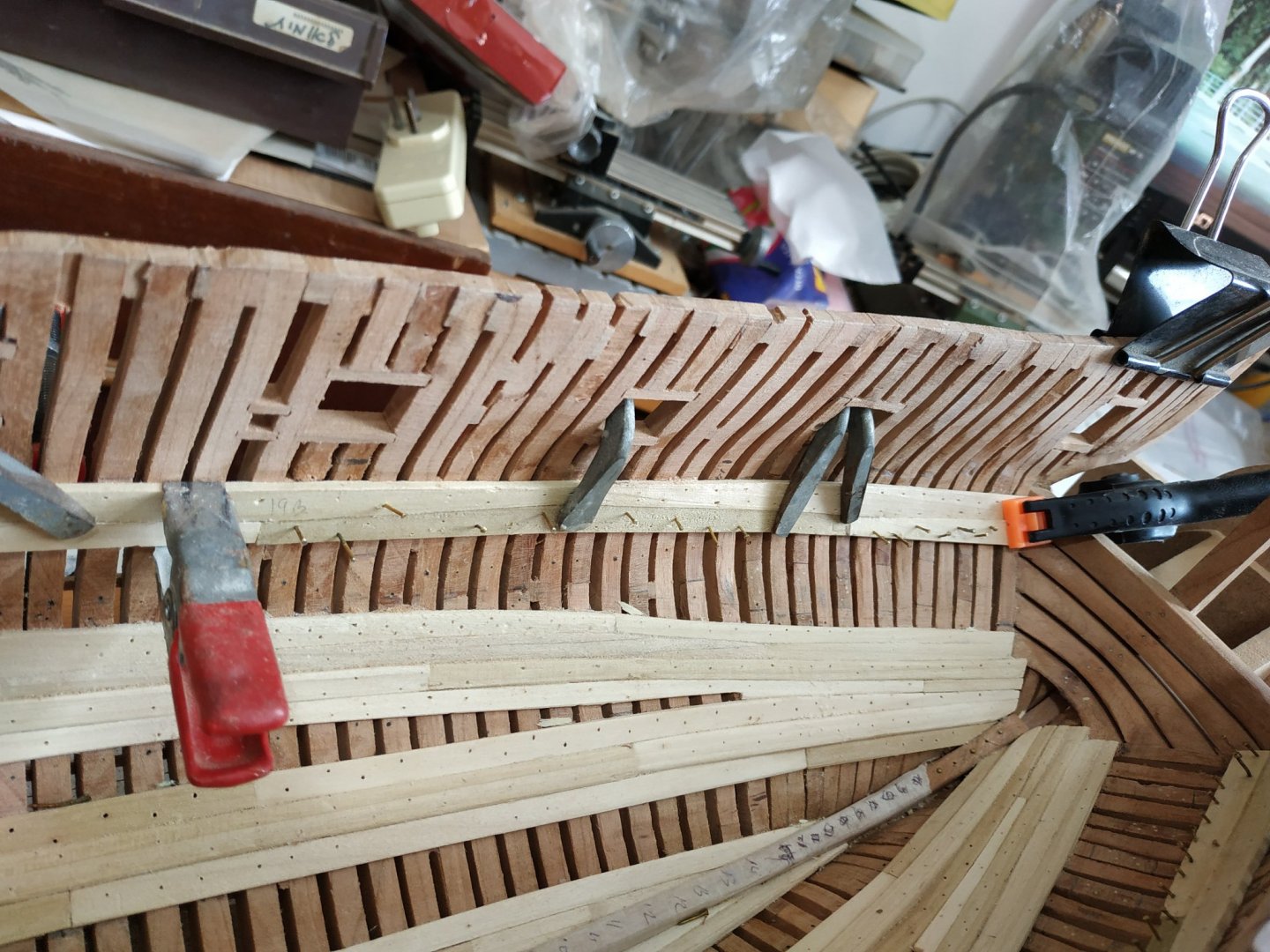
LOWER DECK BEAMS (To be fixed temporarily to enable building and positioning of support posts) Size 4.24mm wide and 3.18mm deep.-with round up (curve) of 1.6mm Plans have patterns for these. TFFM suggests blanks of 4.24mmx4.77mm -total length about 330mm (19 pieces +spare) My usual method, cutting out a printed copy and sticking them to the blank was difficult due to distortion of a long narrow piece of paper. Tried a wider paper and used spiral sander to shape-too much inaccuracy and variation. (1st batch of 20 wasted) Next I tried a block 5cm -much easier to control and more accurately the upper(convex) side, the lower side more difficult to hold the thinned block at 90deg to the table. After the first failure, I made it thicker and better controlled with a pattern on either side. This was then ripped in table saw to the required width (4.24mm).Some further waste as the curved block was difficult to control 100% The resulting pieces were then reduced to the 3.18 depth by several passes between the controlling block and the milling bit. Next time I will try forming only the convex surface before “slicing” and the form the concave surface with the mill.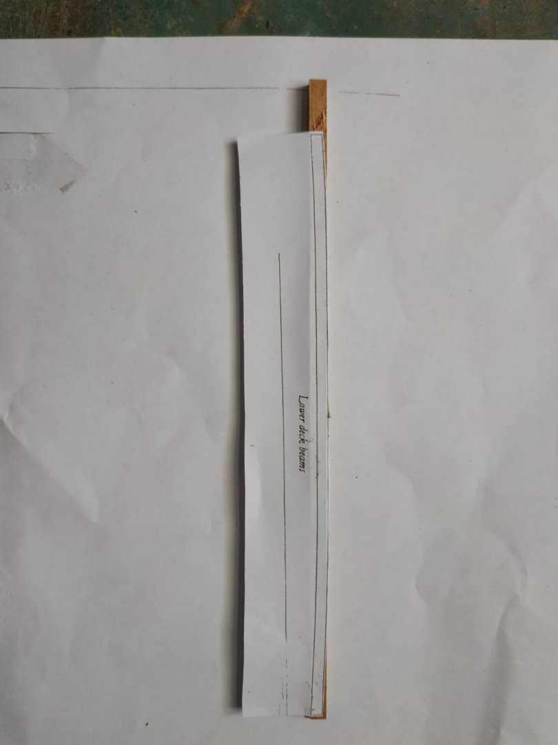

-
Swan-Class Sloop by Stuglo - FINISHED - 1:48
stuglo replied to stuglo's topic in - Build logs for subjects built 1751 - 1800
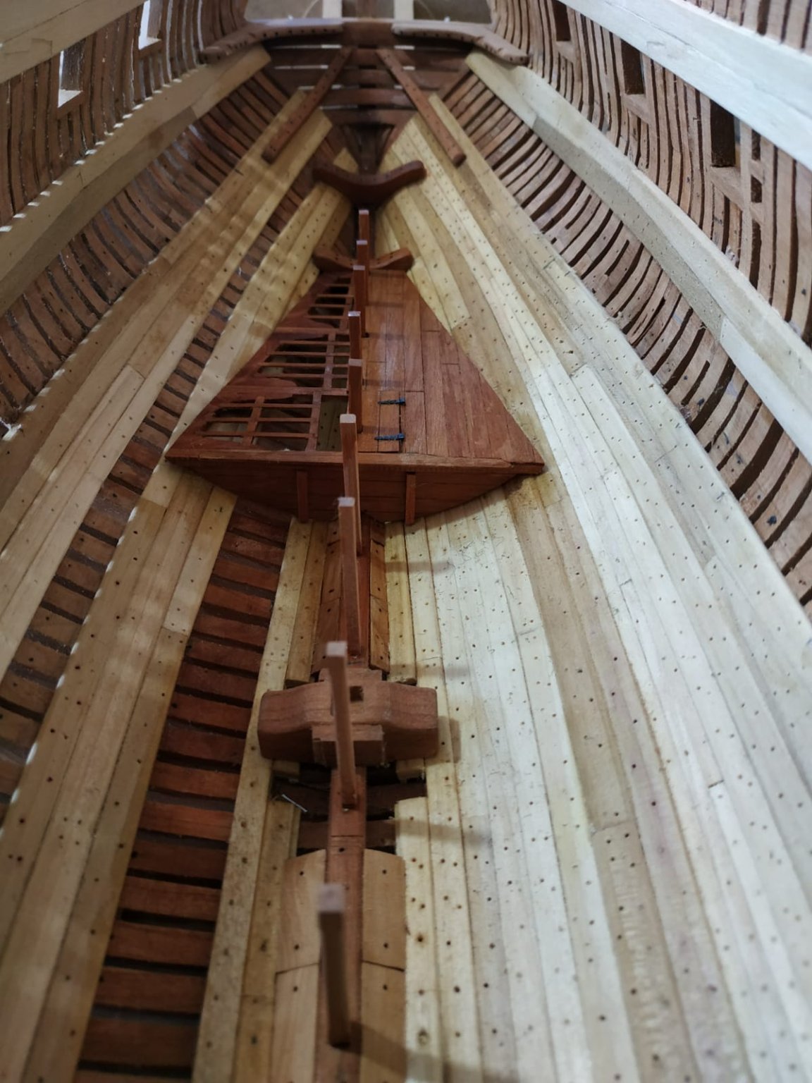
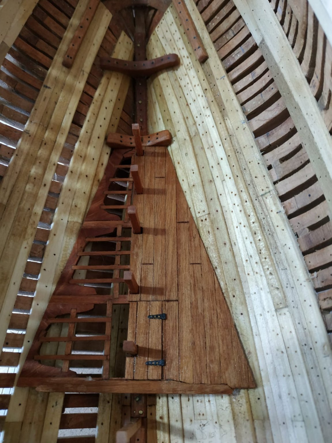
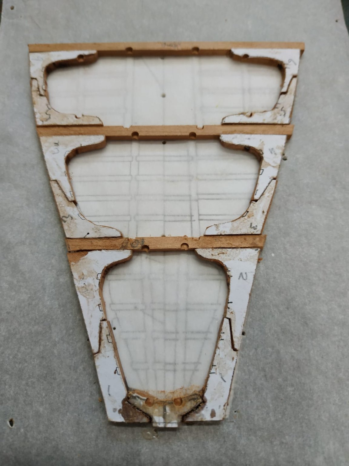
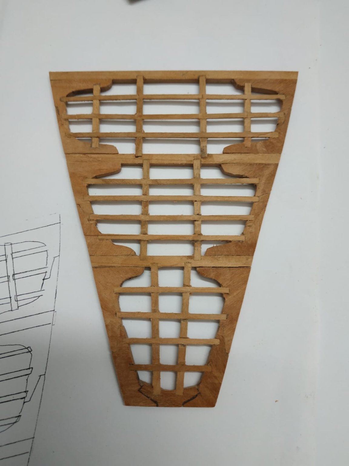
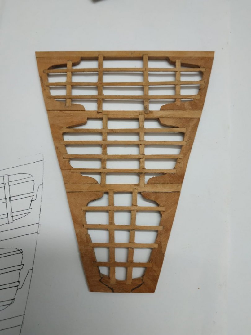
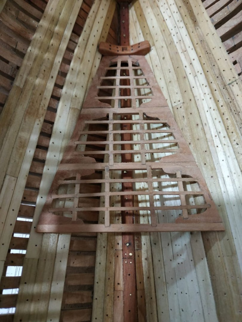
Chapter 5, TFFM 50 weeks into this build and what a learning experience (most of which I have forgotten). Description of filling the main hold with ballast and barrels. This will not be seen and I did this with my previous model (Victory Bow) and at this stage I do not find it very exciting and I will skip this and proceed to the -- Aft Platform. This is the aft part of what could be considered the lowest deck. The middle 3rd was not built. Referring to the Atalanta sheer plan, 3 support beams running across the keelson are located. The advice is to mark their heights directly onto the strakes-I found this difficult as I’d oiled the wood in this area added to an acute angle. I therefore made a pattern of the area between keelson and platform, having checked that the keelson height was accurate.Gluing this to a blank, gave me the line I wanted and the support for the template I needed to make for the platform. The beams are 3.45mm wide and 2.65mm deep.The upper surface is cut at 3.5deg with a tilt table saw (1st time I have used it so), to allow for upward slope aftwards. The foremost beam is located above the gap left in the limber boards so the bulkhead is affixed to its aft side. The pattern of the platform didn’t fit so well, particularly aft ⅓. This widening of the “tail” needed some adaption of the lodging knees and rear end redesigned. These knees are from 2.65mm blanks. (I have difficulty with accurately cutting small pieces with the scroll saw- no matter how I try to hold them,they jump and often break.I use the band saw for rough outline the the CORNERS of the band sander.) The carlings -longitudinal beams, 2.12mm wide /1.6 mm deep The ledges-cross sub beams, 1.6mm wide/1 mm deep. Located and started mortise with a 2mm milling bit, recess squared off with 2mm chisel blade. The ledge/carling mortise defeated me. Maybe too tired and in a hurry to make progress ? Anyway, I joined both pair of mortises into a groove and ran the ledge continuously over this. I”ll add a false “seperating” line later. ** I used pva glue except for aft piece, where I used epoxy. The result is a bit fragile and should have used epoxy for all the major joints.** The edges of the platform need shaping -sharp angle- where the meet the strakes. This part is put to side -NOT FIXED- until several more stages are built/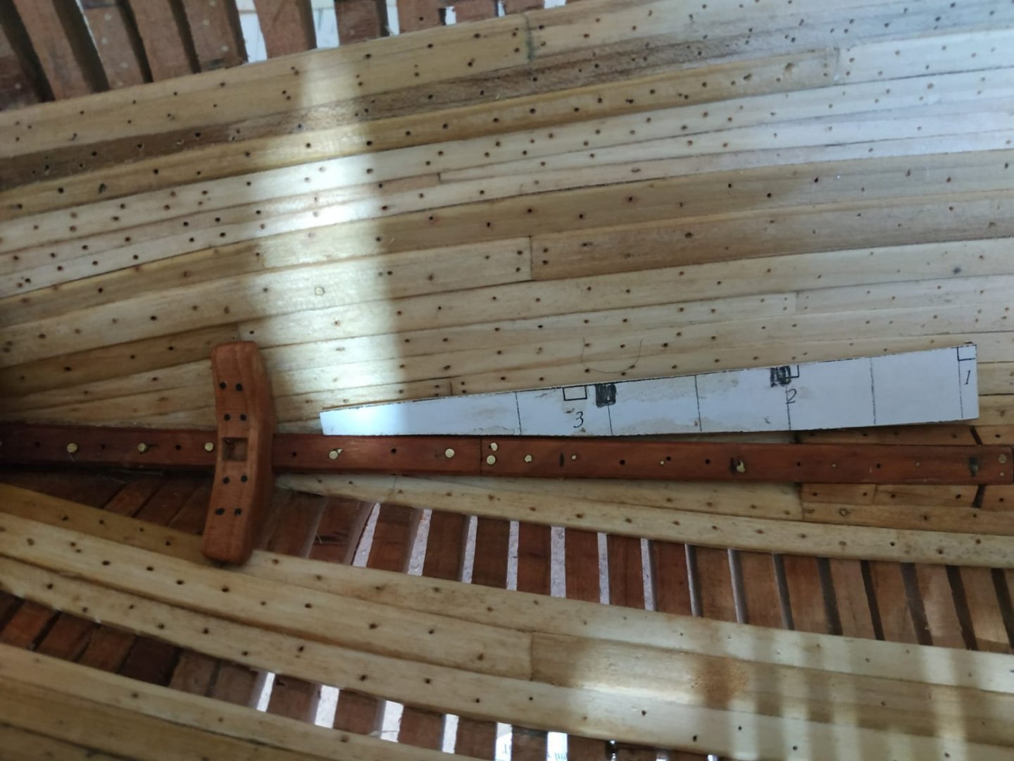

-
Swan-Class Sloop by Stuglo - FINISHED - 1:48
stuglo replied to stuglo's topic in - Build logs for subjects built 1751 - 1800
THE WING KNEES They connect the wing transom to the side of the hull. The aftermost beams of the deck mortised into the “arms”. The basic thickness is 3.71mm, the arm against the wing transom is 31.8mm long-upper surface continuous with upper surface of transom. The side arm is 44.5mm long and rests on the clamp.This arm is “let down” by 0.53 on the clamp, but I decided instead to use a thinner blank of 3.18. (As I understand it, although this arm rests on the clamp, it acts like a clamp but the beams are level into the mortise rather than proud and therefore forms aft base of deck- I await to be enlightened) By following the surface of the transom, it cants upwards slightly. The surfaces to be fixed need some shaping, especially at the corners. Chamfering lower edge only, 10 bolts + pair at either end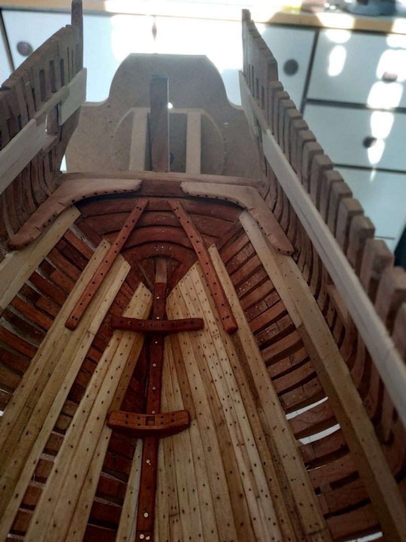
-
Swan-Class Sloop by Stuglo - FINISHED - 1:48
stuglo replied to stuglo's topic in - Build logs for subjects built 1751 - 1800
SLEEPERS These are a pair of “unfolded” knees, either side horizontally across transoms and aftermost cants, roughly in line with strakes. No pattern given, simply trial and error. Size given as between 64-76mm, of which about ⅗ across the cants. Thickness 4mm, step at end of strake. Chamfered and treenailed.- Not totally satisfied with my effort-may redo later
-
Swan-Class Sloop by Stuglo - FINISHED - 1:48
stuglo replied to stuglo's topic in - Build logs for subjects built 1751 - 1800
Your interest and oversight is much appreciated. -
Swan-Class Sloop by Stuglo - FINISHED - 1:48
stuglo replied to stuglo's topic in - Build logs for subjects built 1751 - 1800
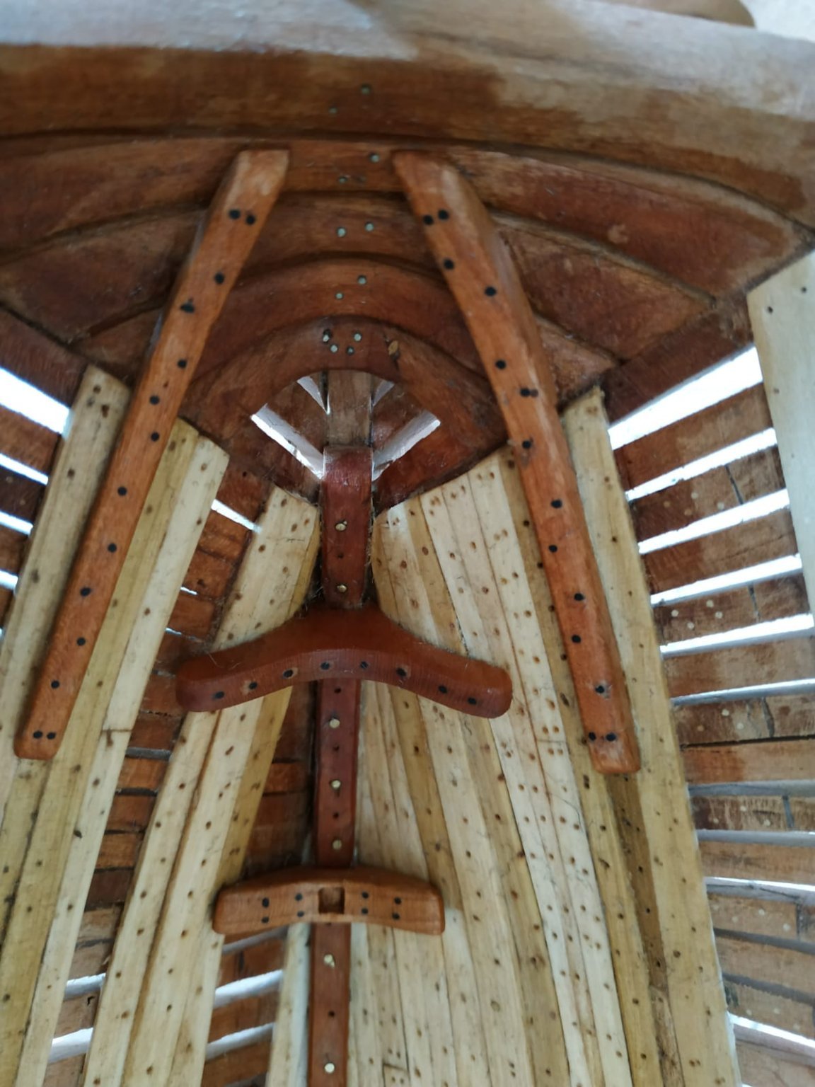
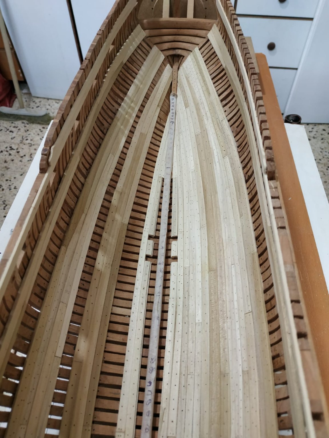
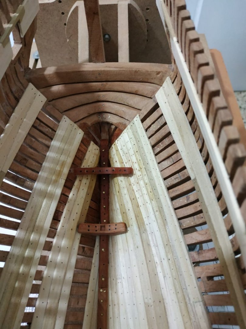
Breast Hooks Similar to aft crutch, but in the bow, on the stemson. Previously scores cut at positions taken from the sheer plan - similarly the angle at which they sit can be copied.The mortise angled slightly to allow this. Blanks of 4.77mm. Lower (aftmost) Breast Hook -some adaptation of the pattern in TFFM Opening space either side of the keelson to allow thicker “feet” Bolts - one central , others over each strake . Chamfer edges Upper Breast hook Slightly smaller. And ensure the upper arms end can clear the lower deck beams.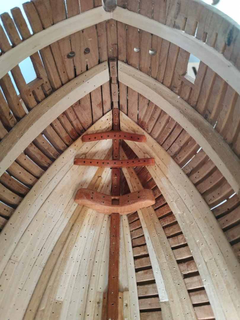
-
Swan-Class Sloop by Stuglo - FINISHED - 1:48
stuglo replied to stuglo's topic in - Build logs for subjects built 1751 - 1800
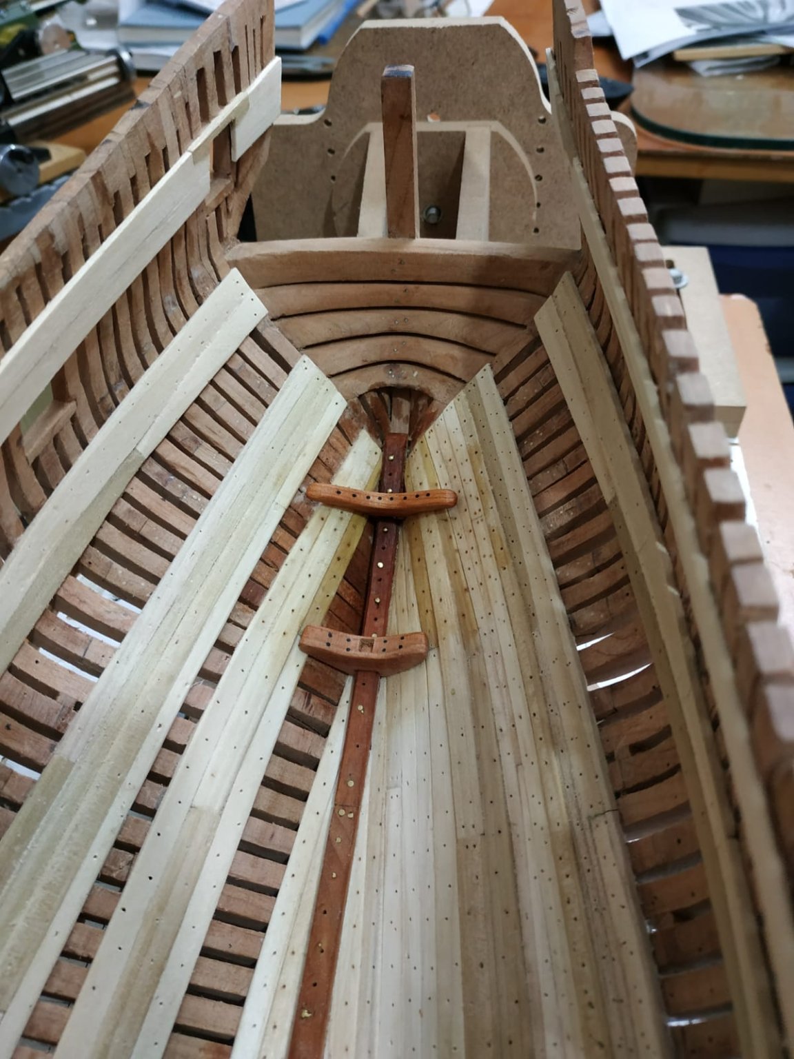
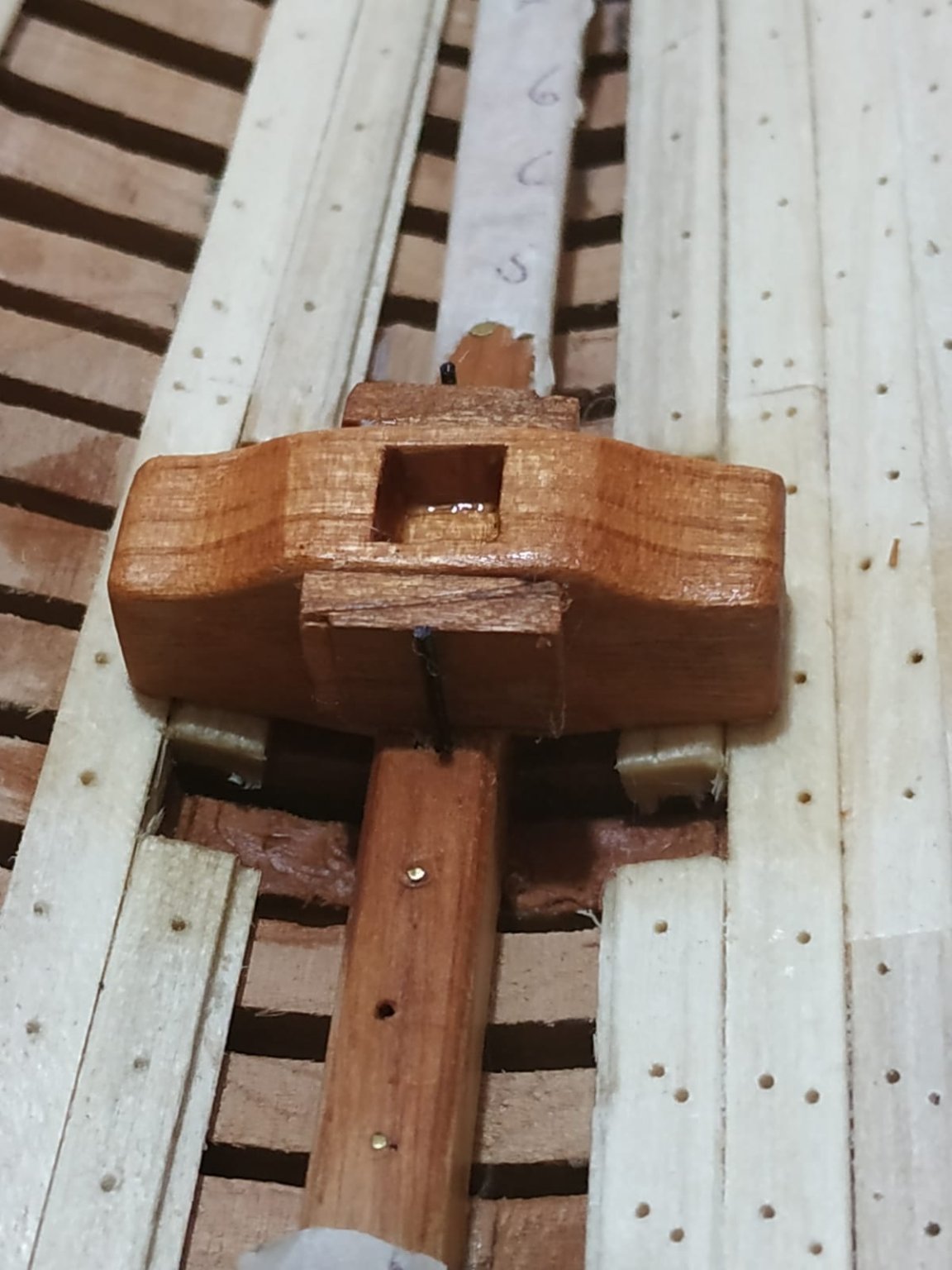
Crutch Aft of the Mizzen Mast Sloping forward on #18 at right angle to the keelson- about 15deg to perp. Using a 4.5mm blank. I thinned down the “thick stuff” to match neighbouring strakes to avoid need of mortises. Also cleared area either side of keelson to allow room for the “feet”. First a card pattern - some variance with pattern in book. Drilled out pre-marked line for treenails and fitted. On review, line not straight !!!- the vice, must have slipped and no longer parallel to base REDO piece.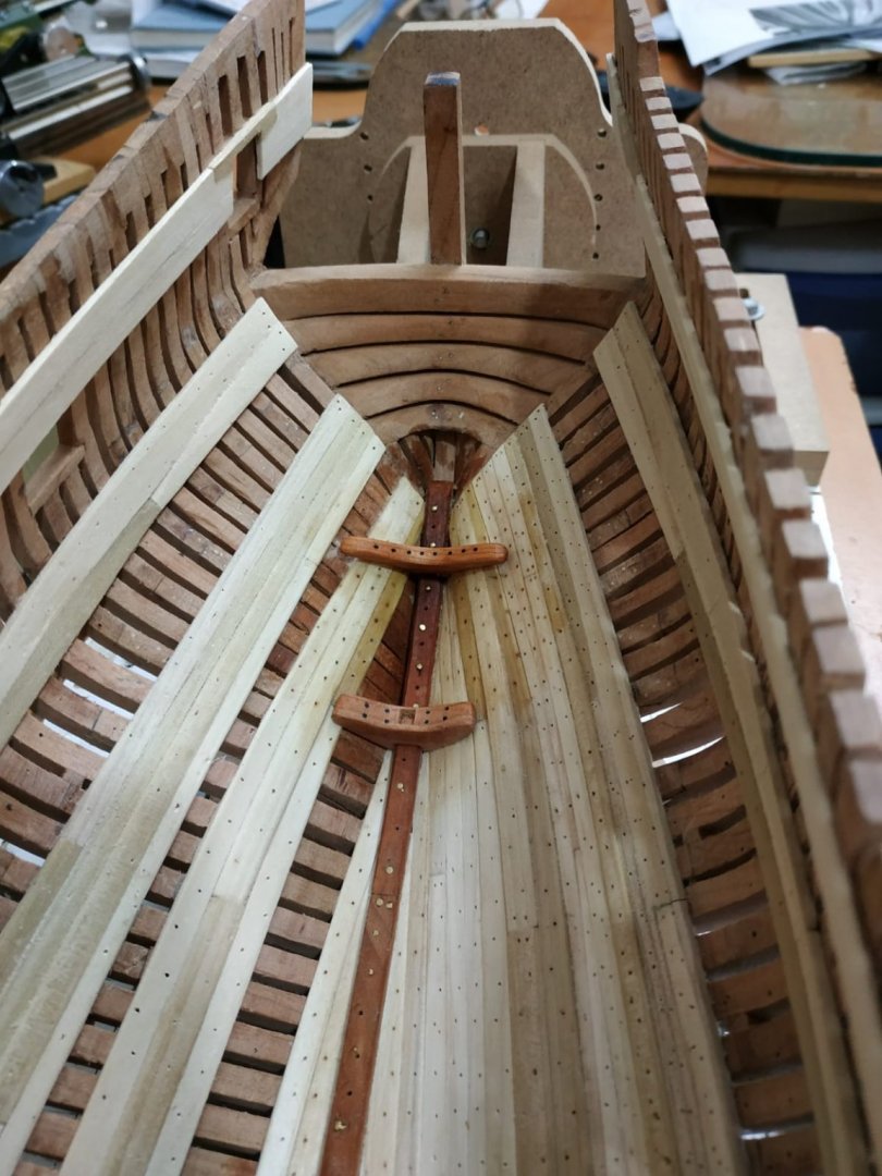
-
Swan-Class Sloop by Stuglo - FINISHED - 1:48
stuglo replied to stuglo's topic in - Build logs for subjects built 1751 - 1800
The Limber Boards Covers over the space between the keelson and groove of limber strake .Extending fore and aft for extent of limber strake groove. (used some pear which I obtained as branches for kindling-varied colour of the grain ? problematic) Varied lengths 30mm+/-, and varied widths due to the curve of the strake. Thickness 1.33mm Note position of wells- no boards. Similarly beneath the shot locker ?closed, and left out for present. Also note places of partitions on profile plan- a 1mm space between boards is left for these. The choice is given for holes (shared) at either end or near the end of each board.(I chose the later-easier) The long edges are chamfered so as to lie on the grove below, and meet the chamfer of the keelson above.
-
Swan-Class Sloop by Stuglo - FINISHED - 1:48
stuglo replied to stuglo's topic in - Build logs for subjects built 1751 - 1800
I'm honoured -
Swan-Class Sloop by Stuglo - FINISHED - 1:48
stuglo replied to stuglo's topic in - Build logs for subjects built 1751 - 1800
The Foremast Step Unlike mainmaststep, this is wing-shaped. A large hook or crutch. Importance of location- (also using 2nd port to help)sits on keelson #7 and #8 cants. 50.88 mm across and 10mm thick. Using blank 60x25x10mm, usual pattern either side, angles require a little adaption but with mortises for ridges in hull planking. Drilling on press and black treenails inserted before gluing in place. The Mizen Mast Step Similar but smaller than the foremast step Width 35, thickness 6.36mm Position -fore-edge on #15 aft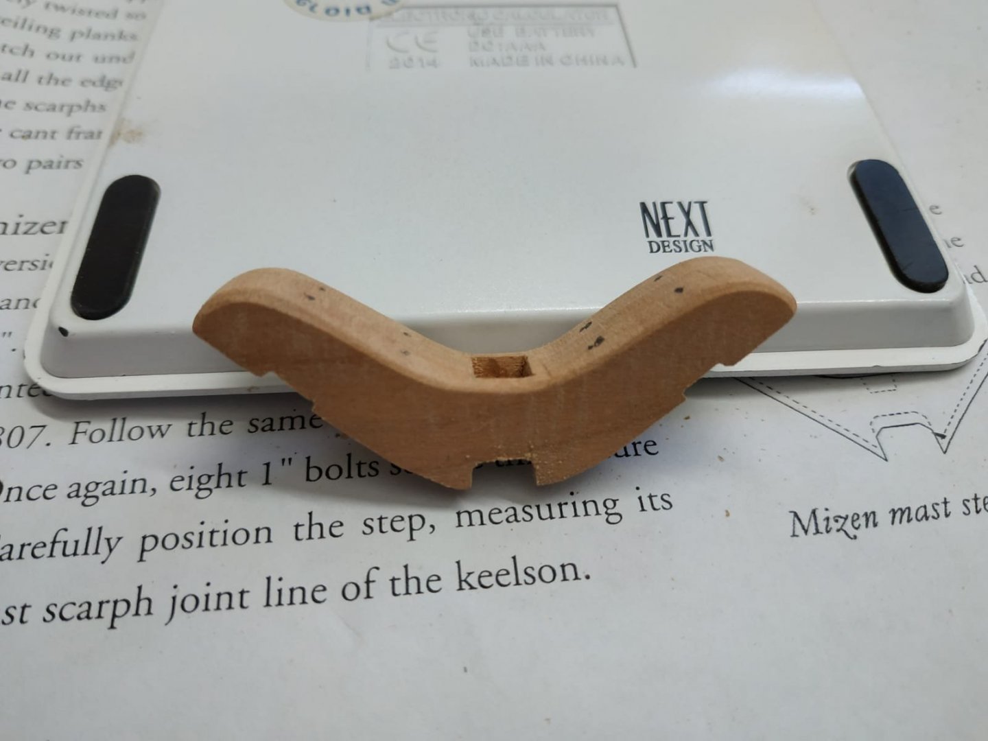
-
Swan-Class Sloop by Stuglo - FINISHED - 1:48
stuglo replied to stuglo's topic in - Build logs for subjects built 1751 - 1800
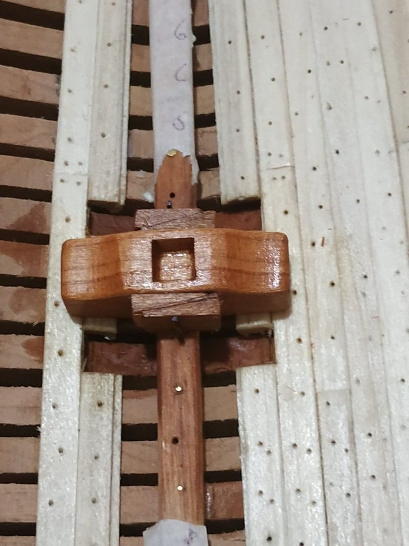
Main Mast Step. Although mid chapter, significant change in building direction necessitates a clean up of the work table!! It is positioned in the “well” between pumps between stations #3 and #4. Shap given in TFFM- photocopies made for sticking either side of blank to aid shaping. The blank is 11.6x10.6x33.39mm The base is shaped/angled to sit on the limber strakes and allowance made for the thicker strakes. A card blank is used for shaping by “hit and miss” and this is superimposed on the printed pattern. These are stuck for and aft of the blank and rough approximation made with milling, file and rasp. The keelson is rising and this is reflected in the change in shape for and aft. I had to deepen the mortise where it sits on the keelson and the overall result was pretty good for a 1st attempt. Then I realised I had no need to deepen this because a gap is deliberately left for the limber passage. New blank and remake. The mortise opening for the mast is 5.3mm square and 3.7mm deep. Milled out and squared off with a chisel. The drawing shows a narrowing towards the bottom of the mortise, but mine is approximate at best. I shaped the upper surfaces of the “wings” to follow the shape of the other mast steps. All upper and side edges are chamfered. This step itself is not fixed by bolts but is moveable fore and aft by means of pairs of wedges held against a large bolt extending upwards to approx. height of center of mast, (10-11mm) I made the wedges by cutting the end of a 9x9mm stick at an angle of 75 deg on table saw. This gave a combined width of 3.5mm and I set the 0.9mm wire I used into the keelson to hold them. I then glued the steps and wedges to the keelson.
-
Swan-Class Sloop by Stuglo - FINISHED - 1:48
stuglo replied to stuglo's topic in - Build logs for subjects built 1751 - 1800
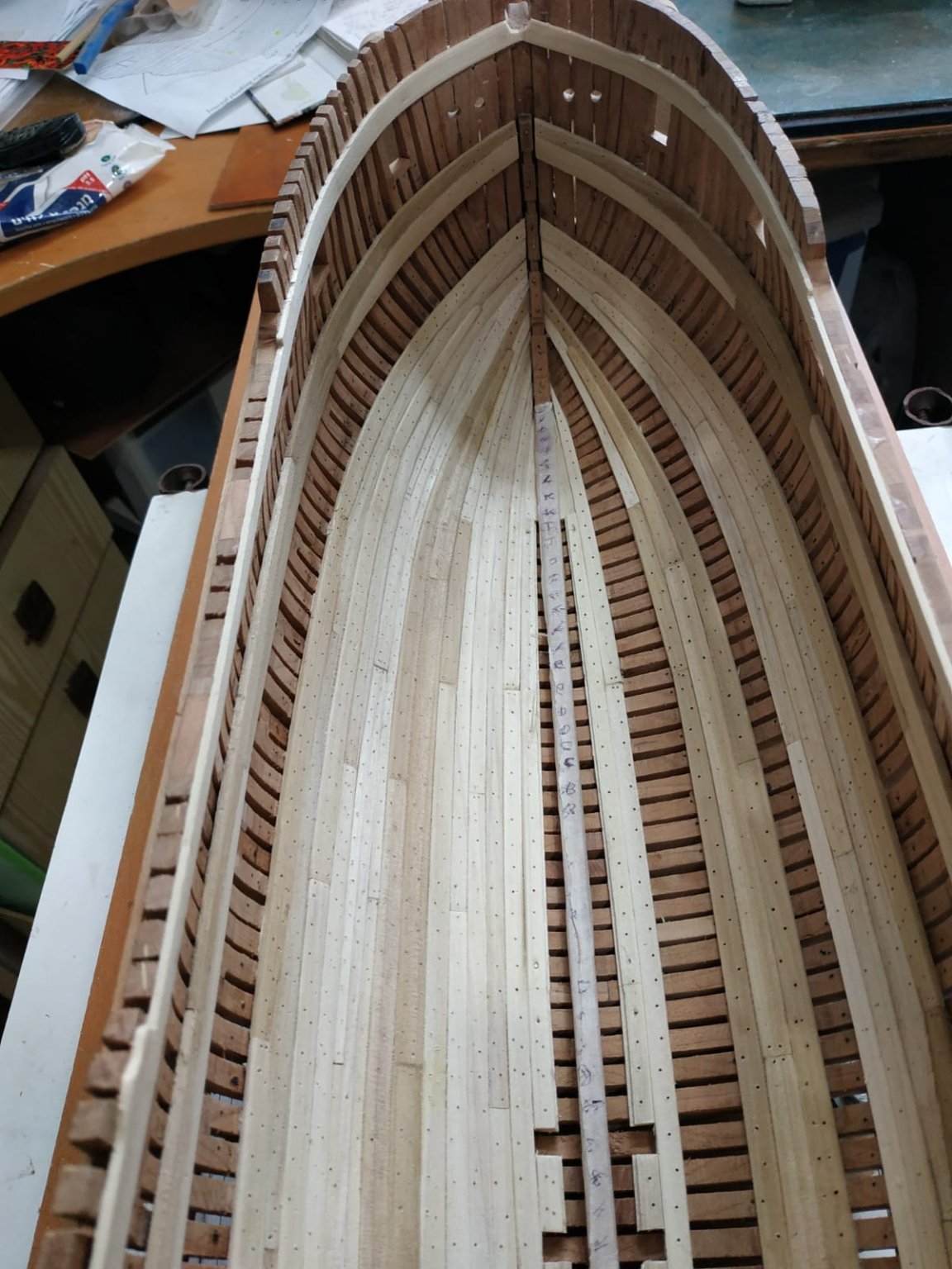
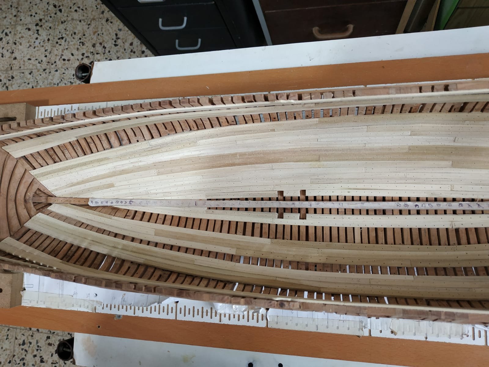
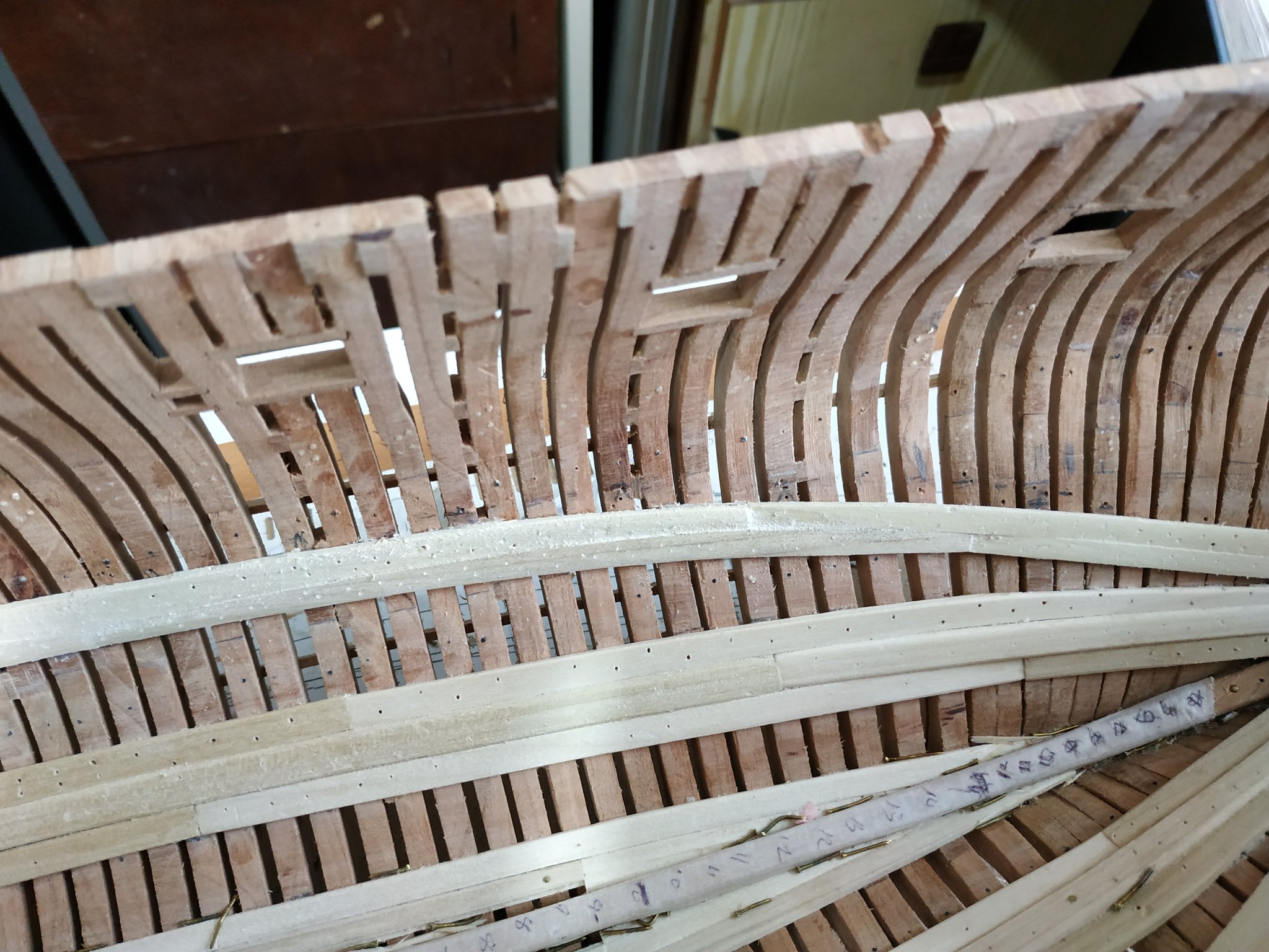
Footwaling-strakes #3-5 These are the filling planks between the limber strakes and the thickstuff. Thickness 1.06 mm.Joints at positions shown on the planking expansion and maintaining pattern of previous strakes. The max. combined width is 17mm (my model) spread over the 3 planks This varies along length and strakes are narrowed proportionately. Footwaling -strakes #9-11 As above, filling between thickstuffs of floorhead and first futtock head.


-
Swan-Class Sloop by Stuglo - FINISHED - 1:48
stuglo replied to stuglo's topic in - Build logs for subjects built 1751 - 1800
On the advice from “druxey” , I realise I chose wrongly, and decided to remake the aft sections of the lower deck clamp and neighbouring strikes #12 to -#15. So that the aft ends fall opposite the 3rd and 4th transoms.


-
Swan-Class Sloop by Stuglo - FINISHED - 1:48
stuglo replied to stuglo's topic in - Build logs for subjects built 1751 - 1800
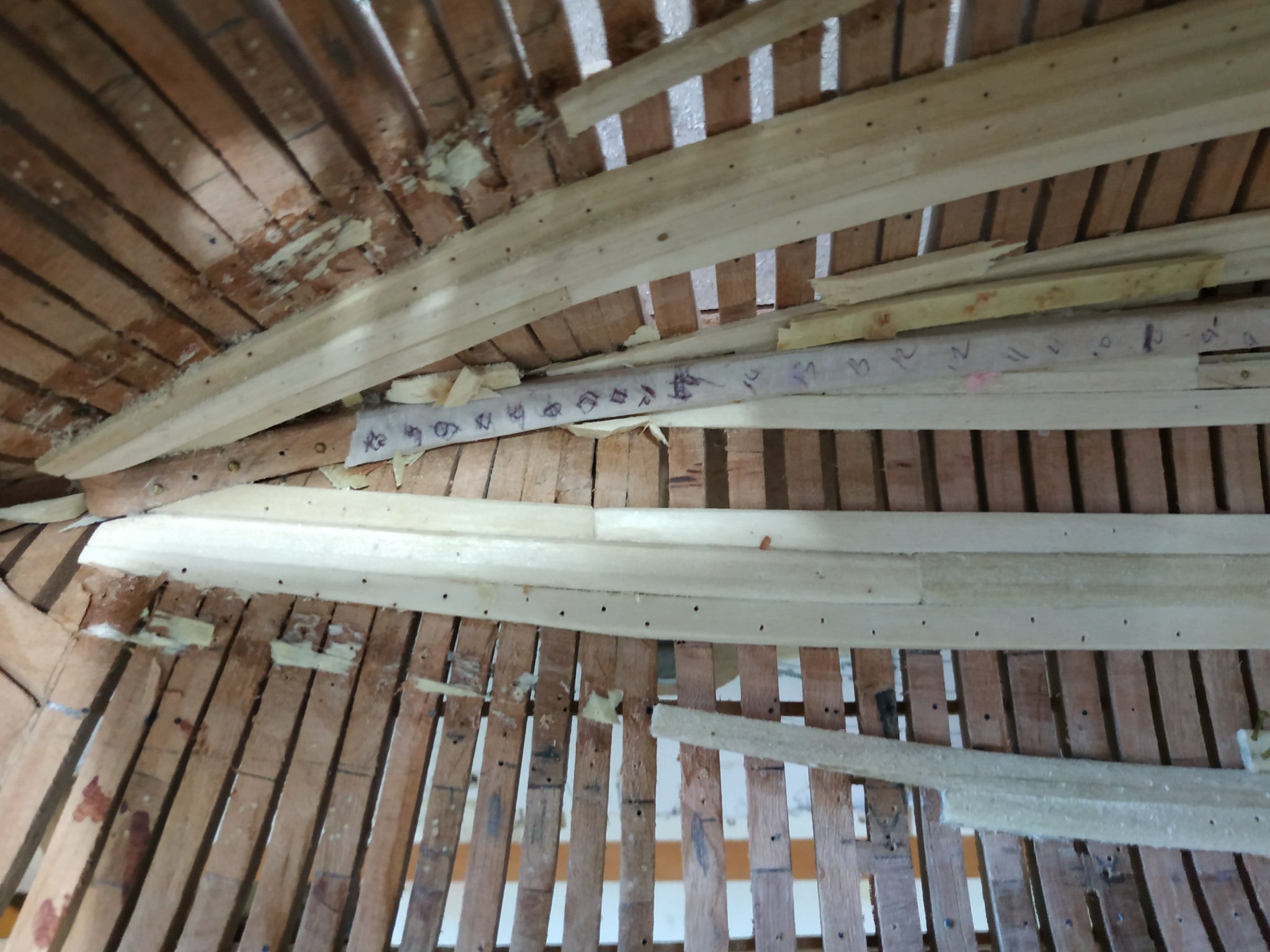
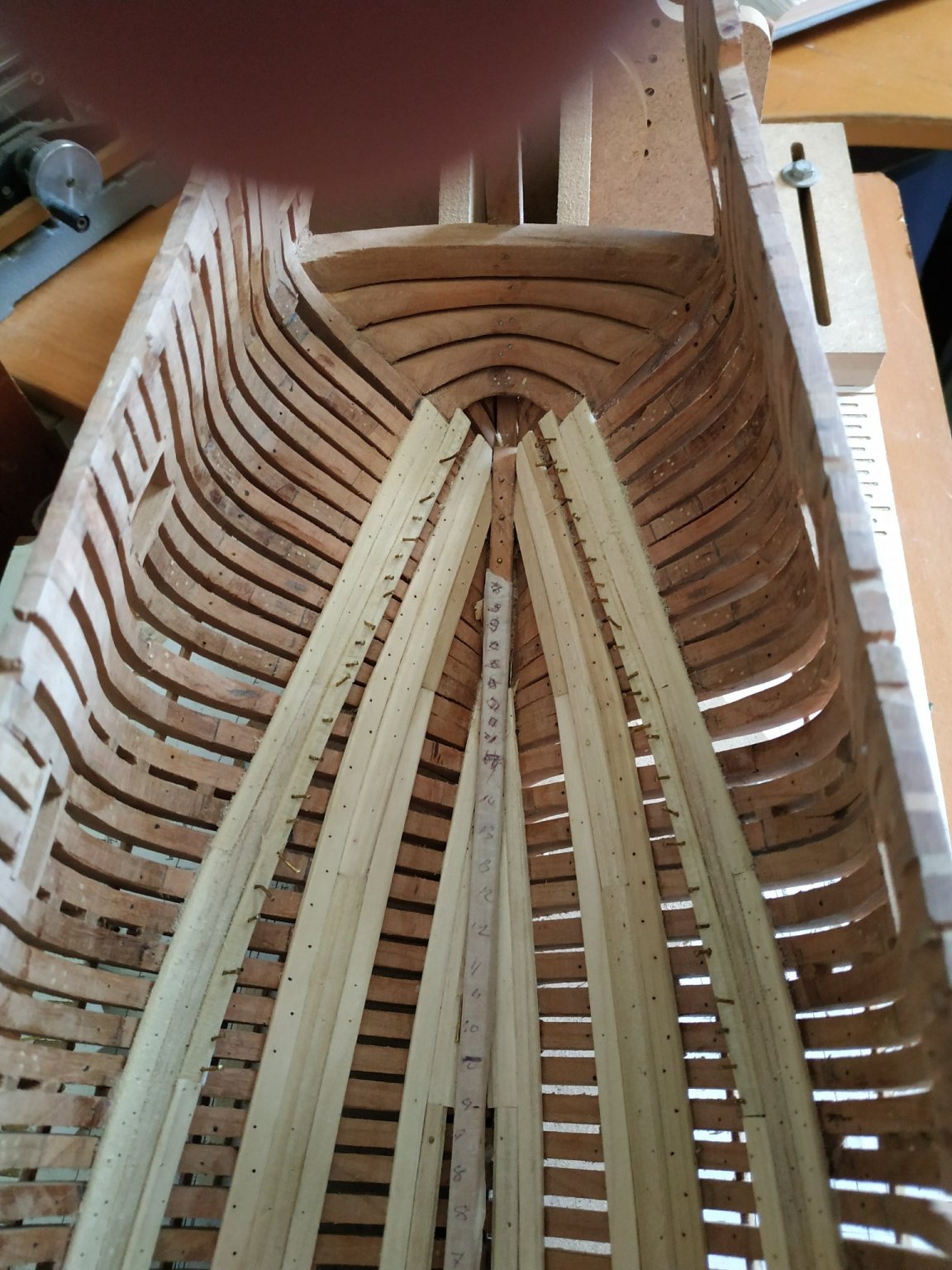
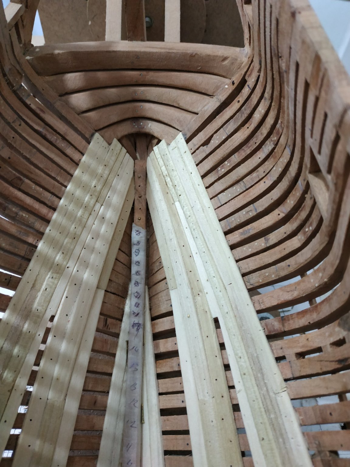
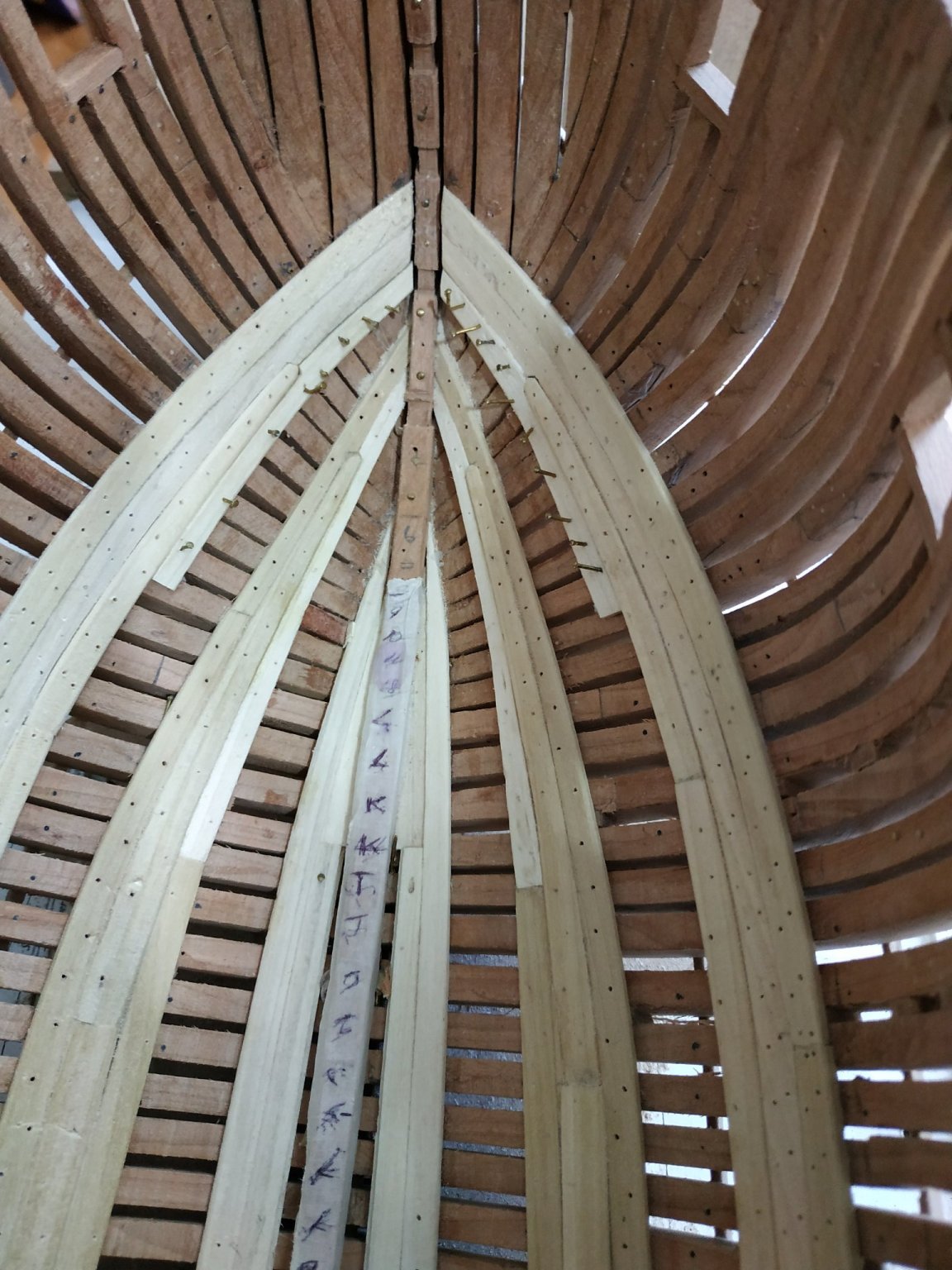
String at waist- strake #25, This is the upper strake at waist, extending between and continuous with clamps of foredeck and quarter deck.(station 5 to #J aft) Joints are hook-scarphed. They are unusually long, suggested length 2.2-2.5cm.They look difficult because I can't remember making them before but turned out easy enough using a stuck-on pattern. The strake has a thickness of 1.6mm but width varies to close gap between the bottom of the upper sills and top of the frames.An additional 2 mm or so in width fore of #G. ANOTHER MISTAKE Having read a couple of pages ahead, I forgot what I was doing and extended this strake to stem and stern.!!!! DA !!!!!DA Aft, not so terrible as Quater deck has an extra strake (#26.)above. So could now check heights and fit this,(Note- #25 runs through aft port-not above) The Forecastle deck clamps, although continuing with strake#25, need recalculation of height because the beams are 2.65mm with NO let down. Using depth gauge and line joins the dots and the excess height is trimmed away. The strake meets its partner temporarily covering lower ⅓ of bowsprit opening. As a check, the vertical distance between upper and forecastle clamps is given as 36mm . The vertical distance aft is40mm -widening aftmost. (TFFM). Note- the foreward part of #26 form a “bulb”shaped widening (above 6th port) and aft the area above the last port is cut out in shape of thin elongated wing shape and replaced with a similar piece of contrasting wood. A small extension is left aft of countertimbers. Chamfer lower lip of #25 alon length.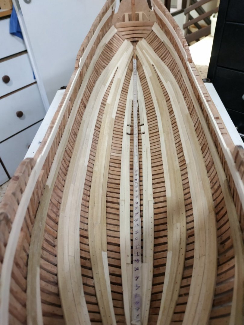


-
I'll have to look, but gave model to my wife's surgeon. Saw the "original" galilee boat in museum next to the Kinneret (Sea of Galilee) . Framed hull pretty well preserved -well worth visit
-
Swan-Class Sloop by Stuglo - FINISHED - 1:48
stuglo replied to stuglo's topic in - Build logs for subjects built 1751 - 1800
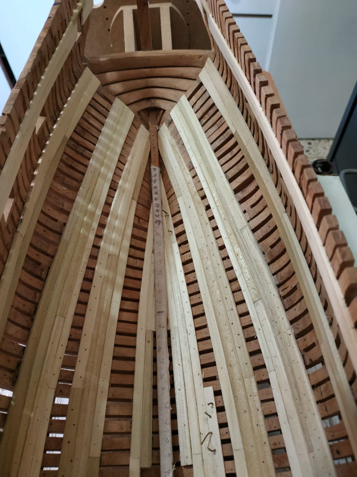
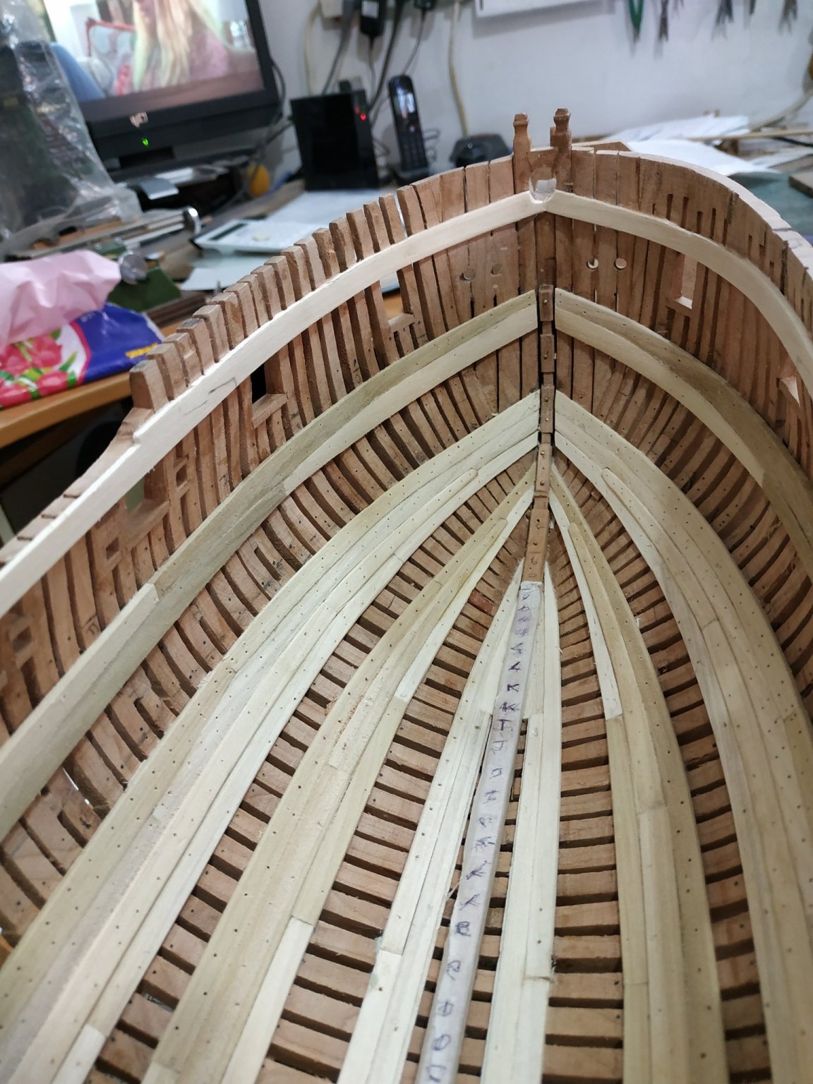
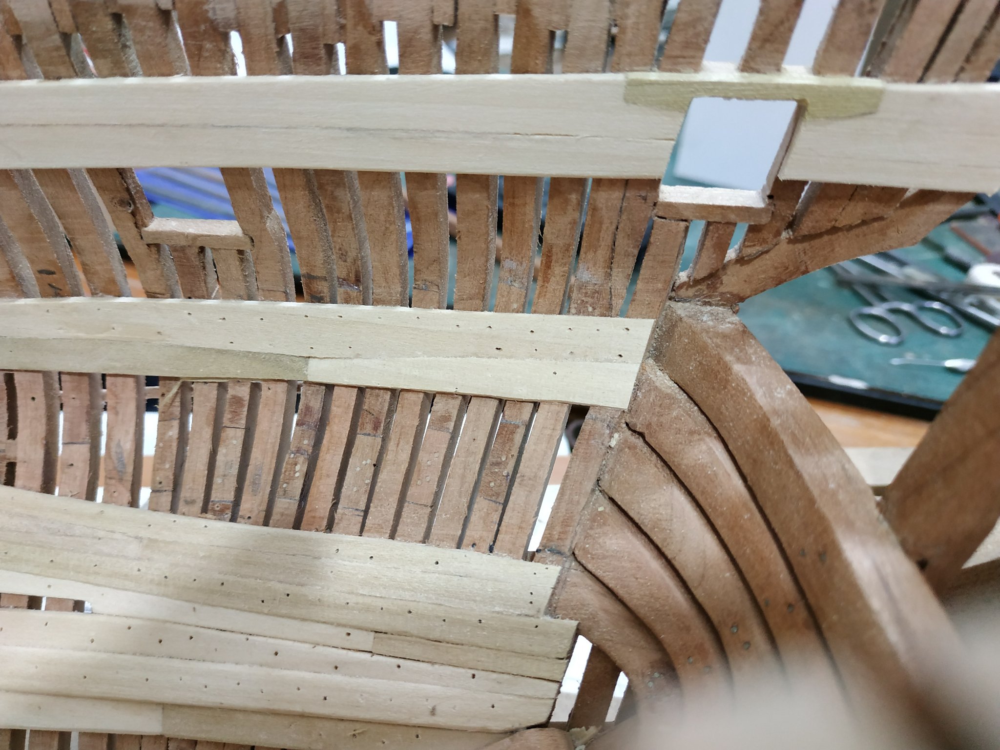
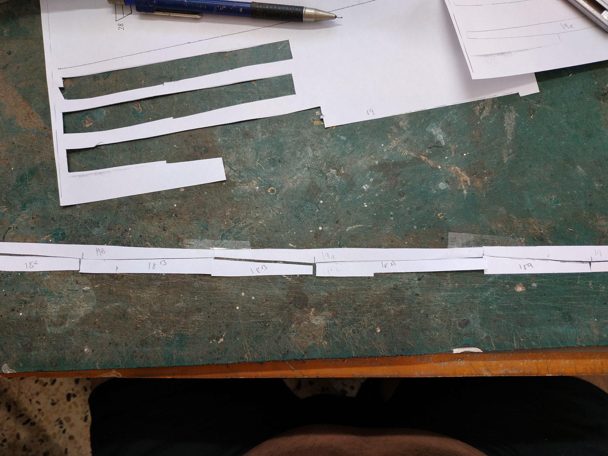
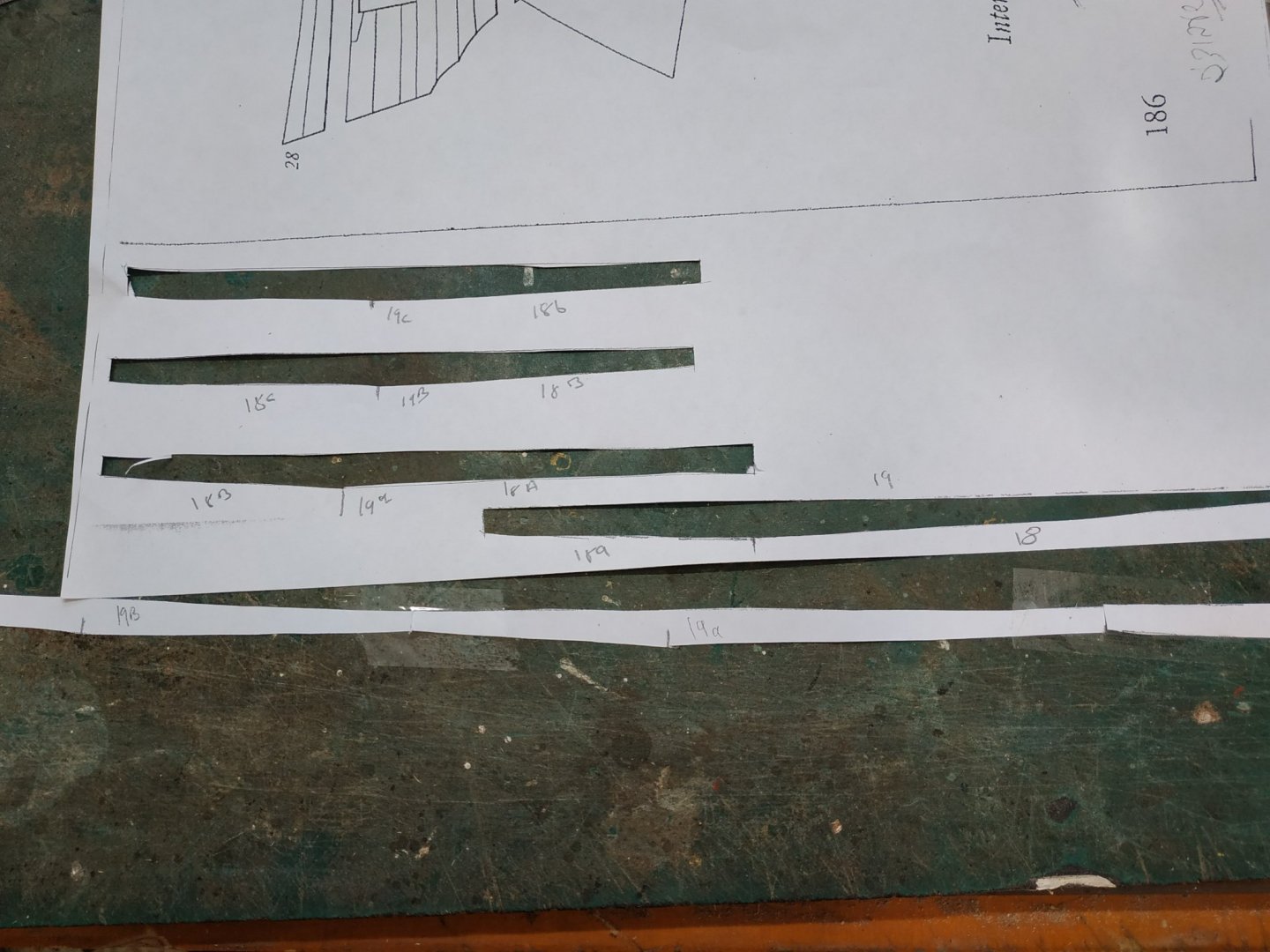
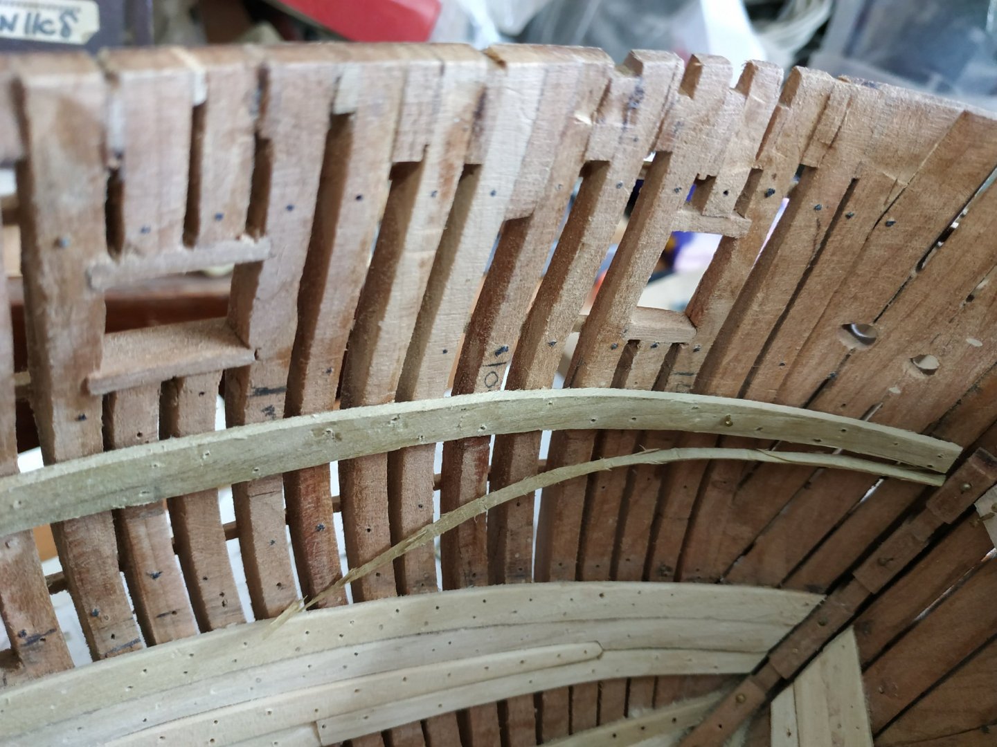
Upper Deck clamps, strakes #18 +#19 Similar to lower deck clamps, i.e. top and butt joints whose combined width is 13.8 amidships. Again establish the line of the upper deck from plan. Allowing 0.53mm let down (recess) lower by 3.18mm (thicker beams), transfer this line to ship. This line should fall 14.58mm below the gun port lower sills. In fact I used this measurement as my guide- the line extending to just above stemson - 0.53mm, and to the top of the wing transom aft. Tapering for and aft. The blank is 2.12mm thick. With is companion #18, this thickness is reduced vertically so that lower edge of #18 is 1.62 mm As with the lower clamp, I use the same thickness for both and then sand to size. The pattern taken from TFFM planking expansion diagram are very different this time and I need to make the strakes by trial and error against a baton placed on the upper line. This is much straighter than the curve on the plan. Position of joints is as indicated, with slight shift from previous strakes. The curve demands bending (hot water and adapted soldering iron) When shapes for sections of #19 ready. Copied to paper so that their neighbour #18 can be drawn and made, and the whole copied for the other side of hull. Also note that at last I can use some fixing clamps. (Gaps between frames too narrow for screw/nut except in one place.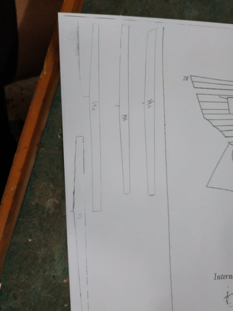


-
Luckily, we had our vaccines in January. Apart from masking indoors, all restrictions are now lifted except for foreign travel. I encourage everyone to get there shots a.s.a.p. and meet fellow modelers in the flesh.