stuglo
-
Posts
707 -
Joined
-
Last visited
Content Type
Profiles
Forums
Gallery
Events
Everything posted by stuglo
-
Swan-Class Sloop by Stuglo - FINISHED - 1:48
stuglo replied to stuglo's topic in - Build logs for subjects built 1751 - 1800
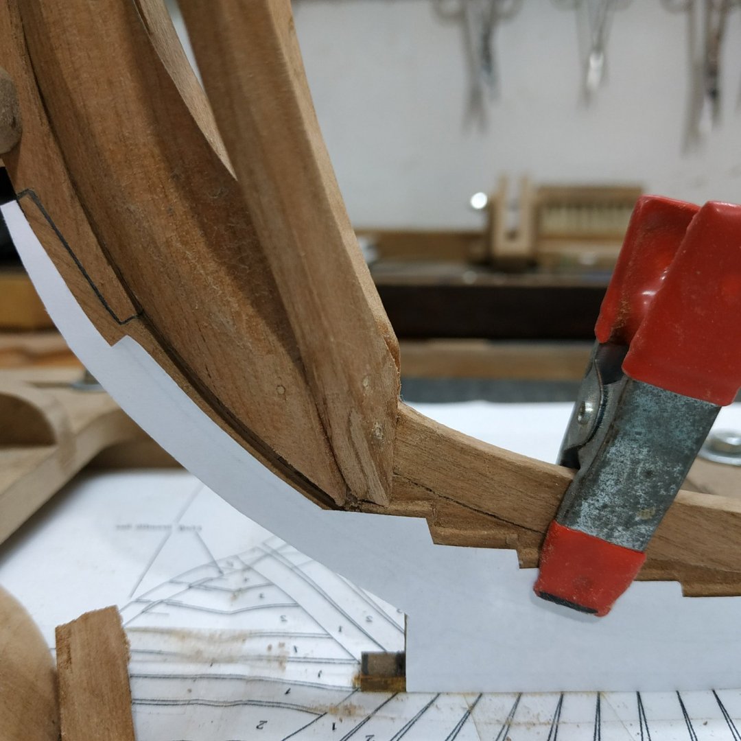
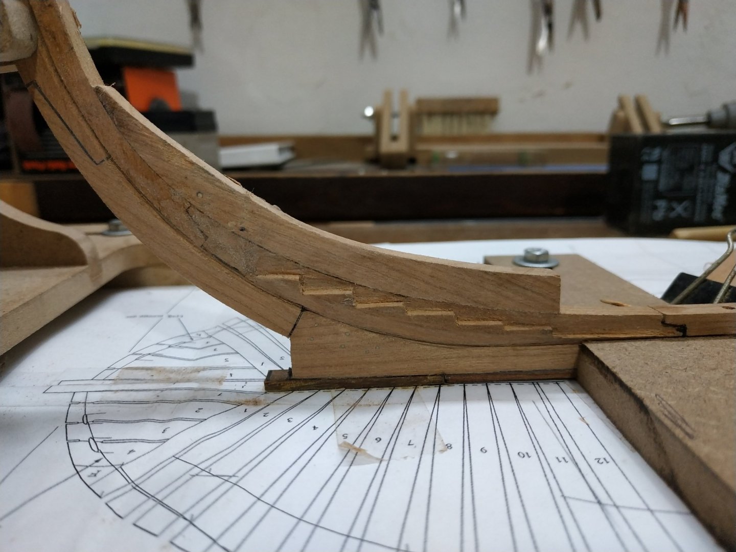
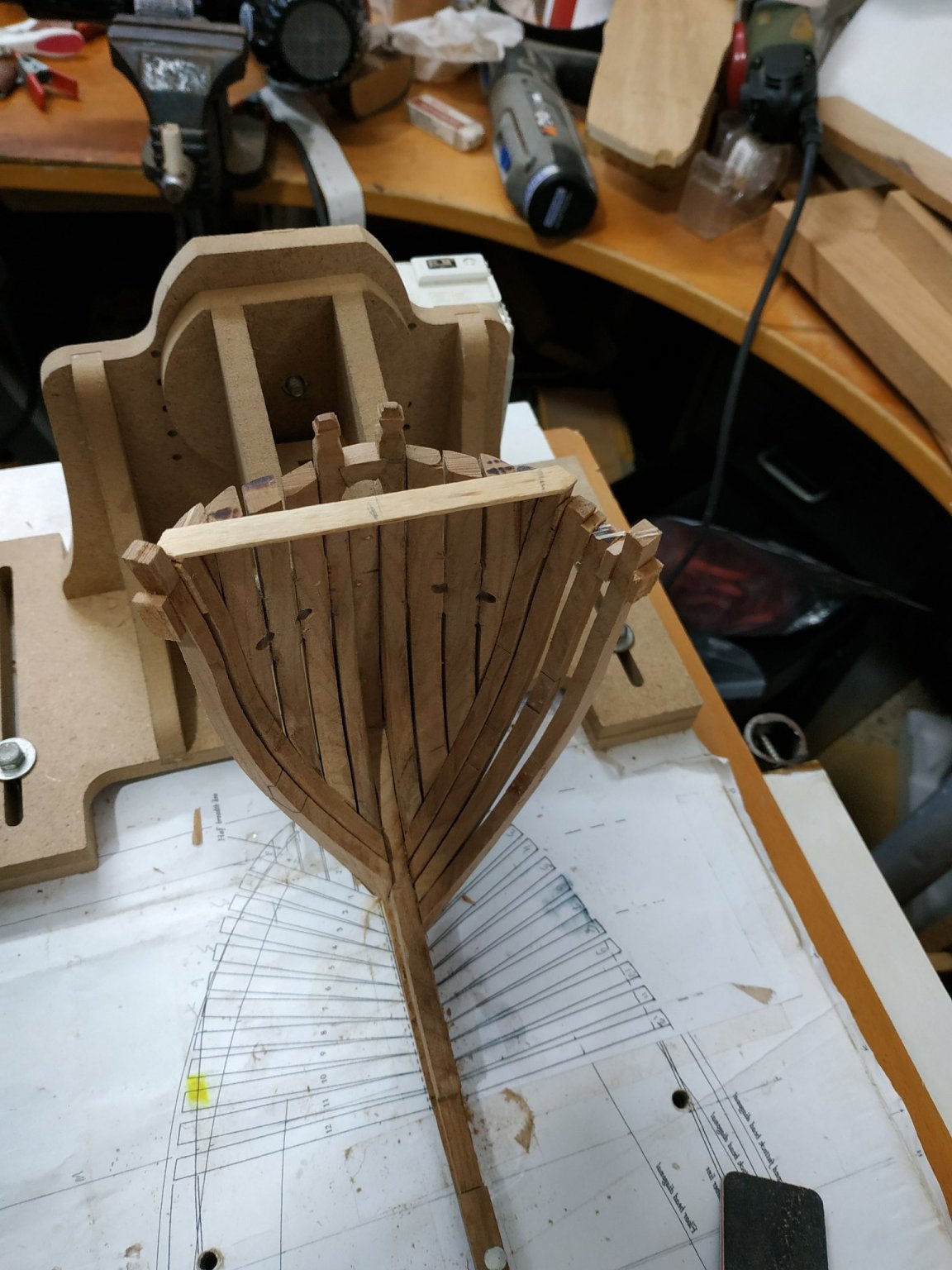
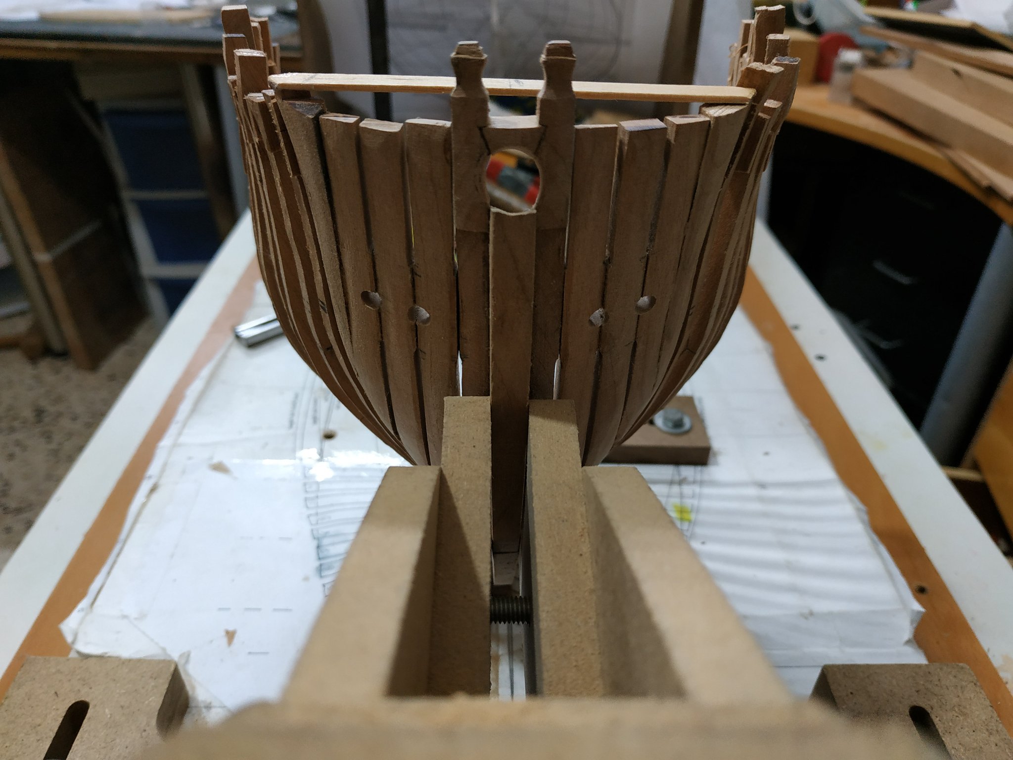
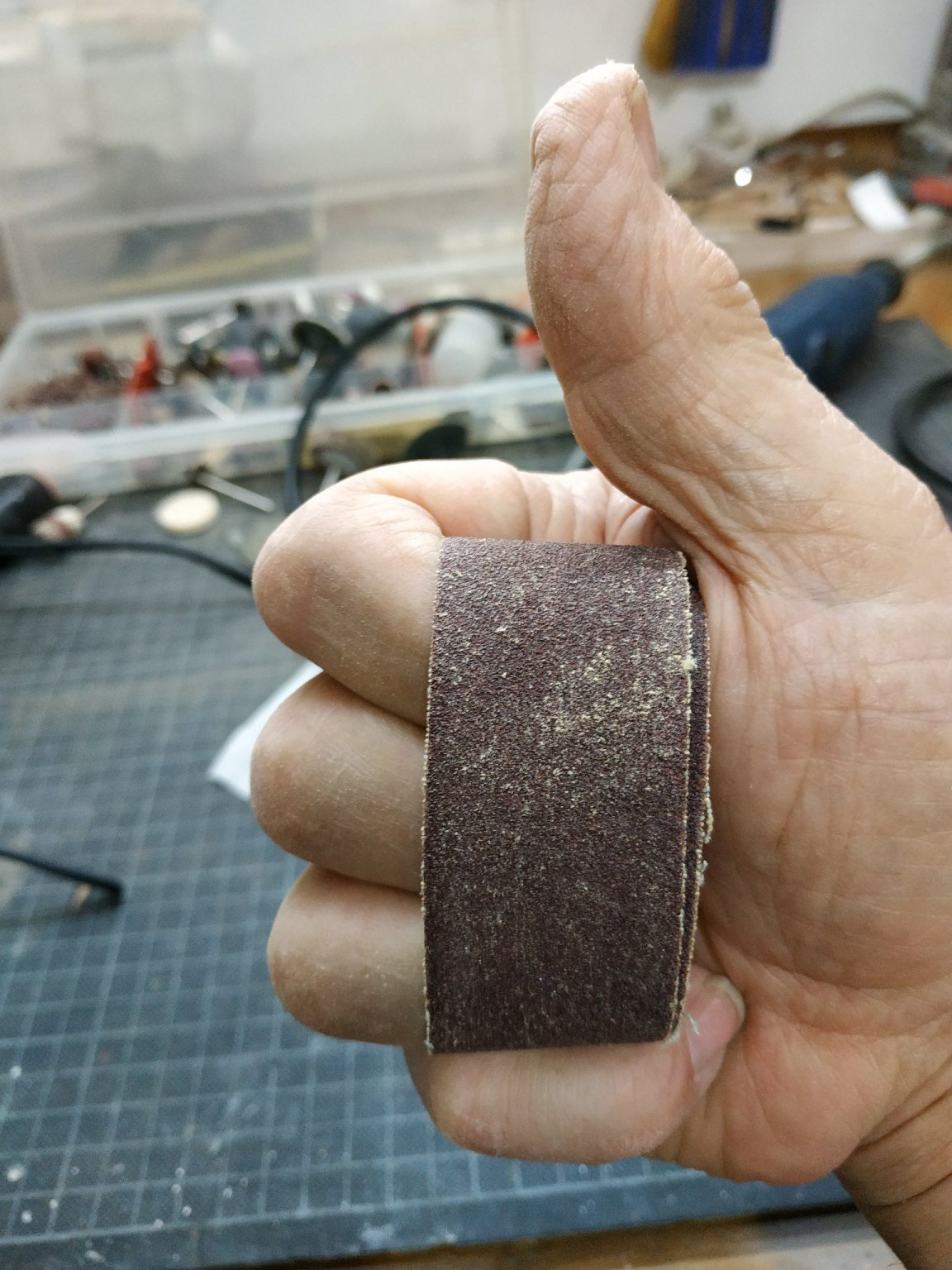
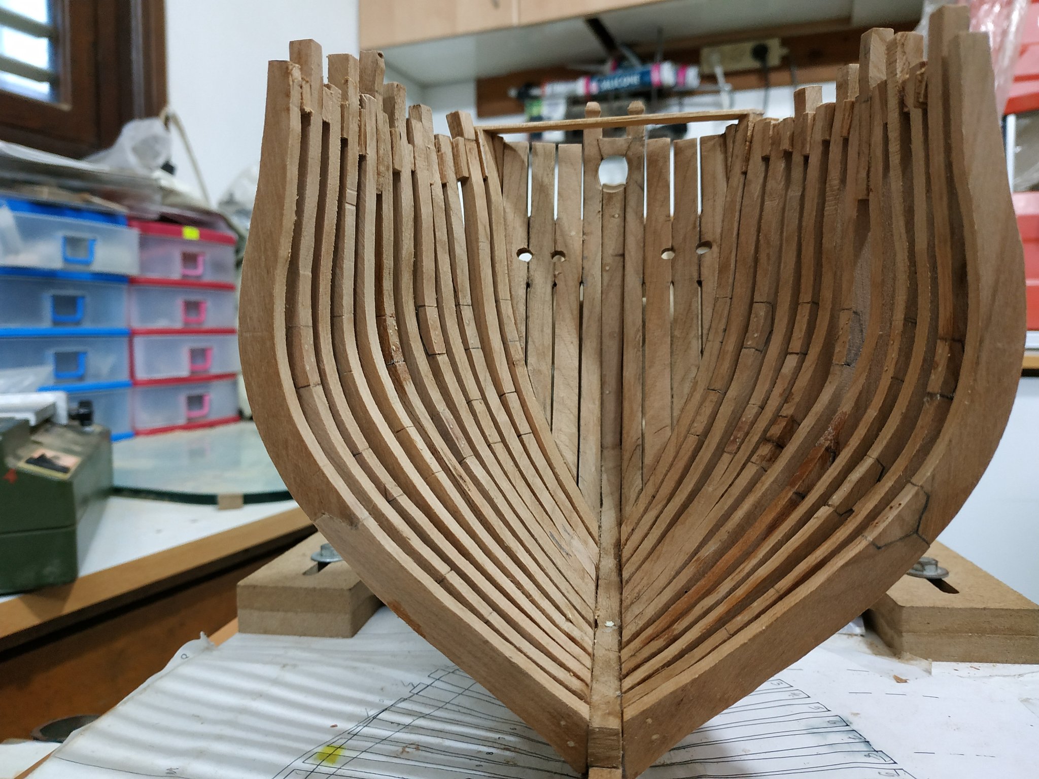
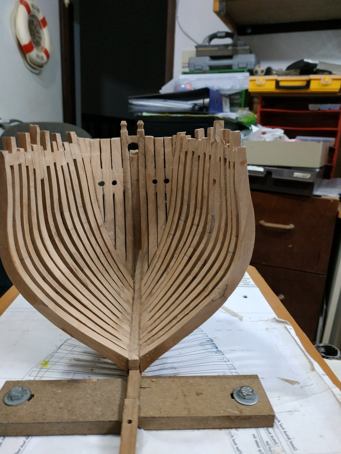
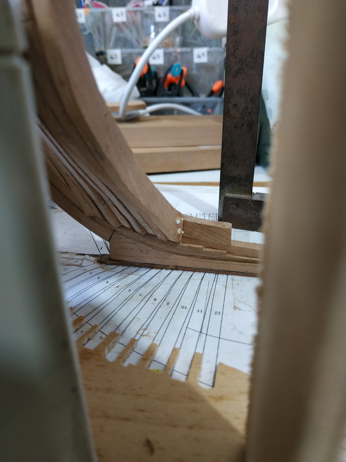
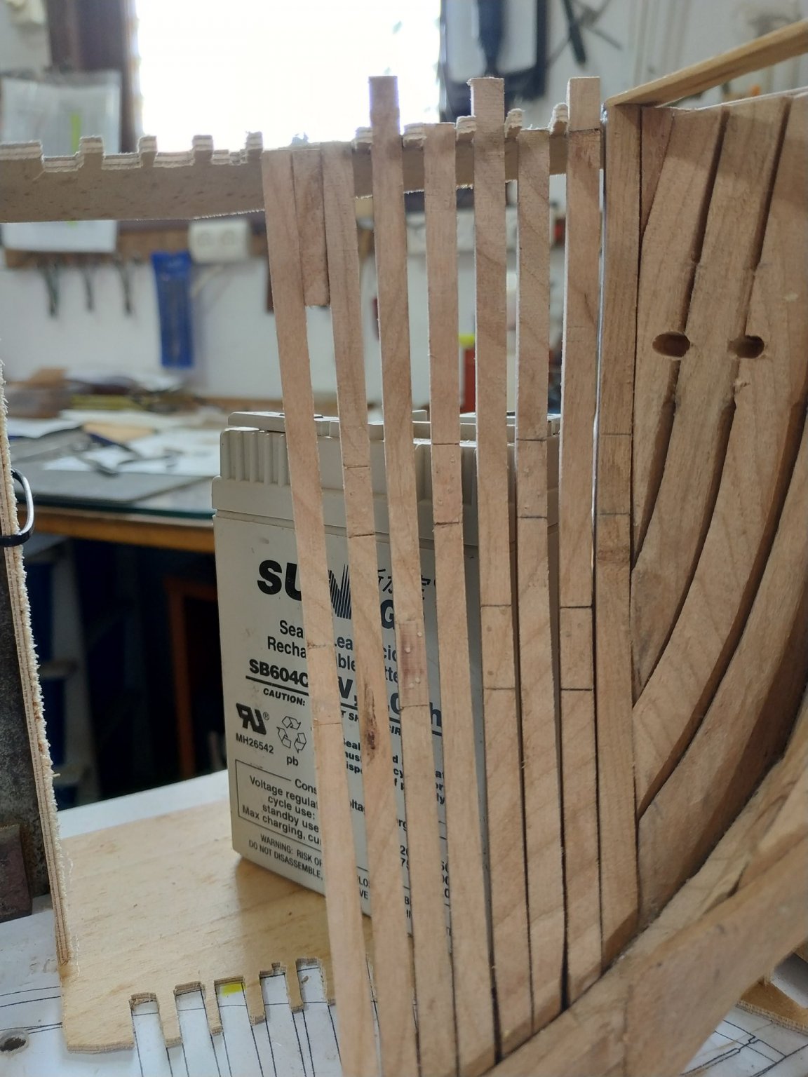
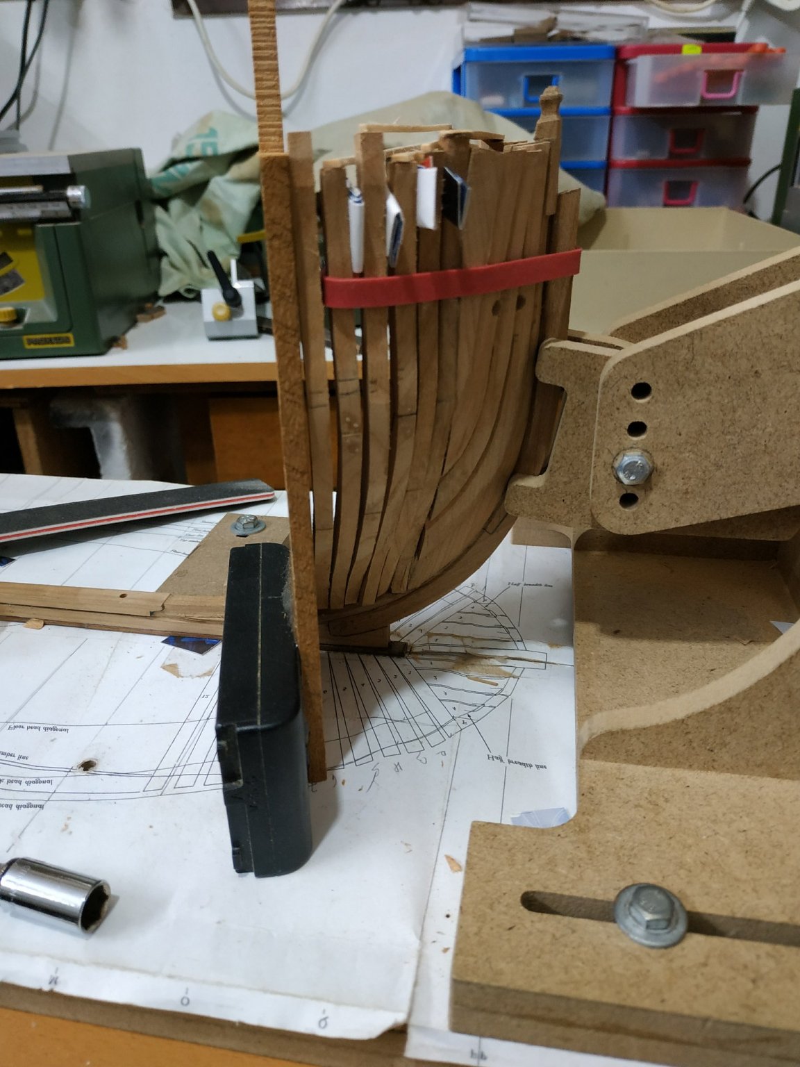
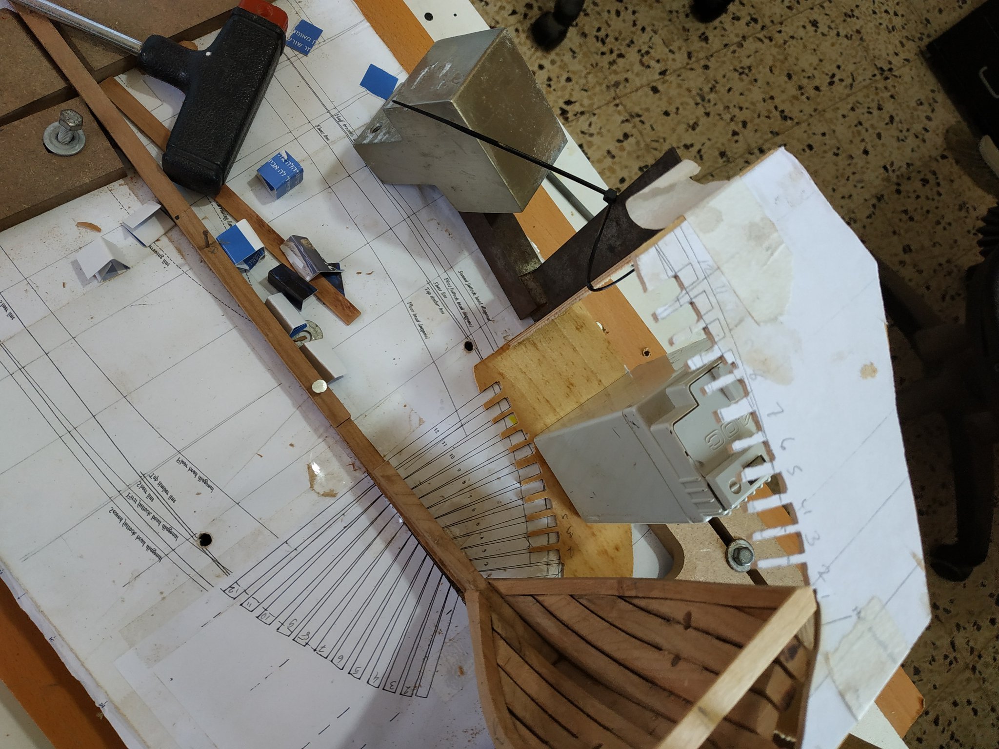
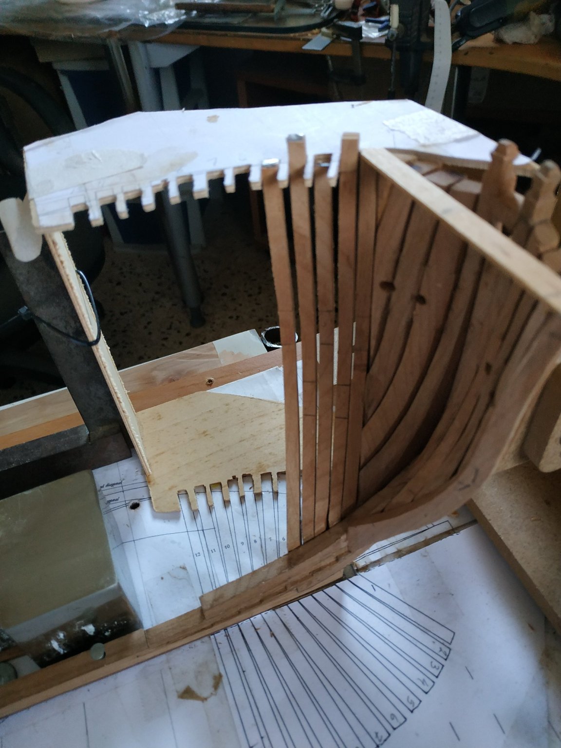
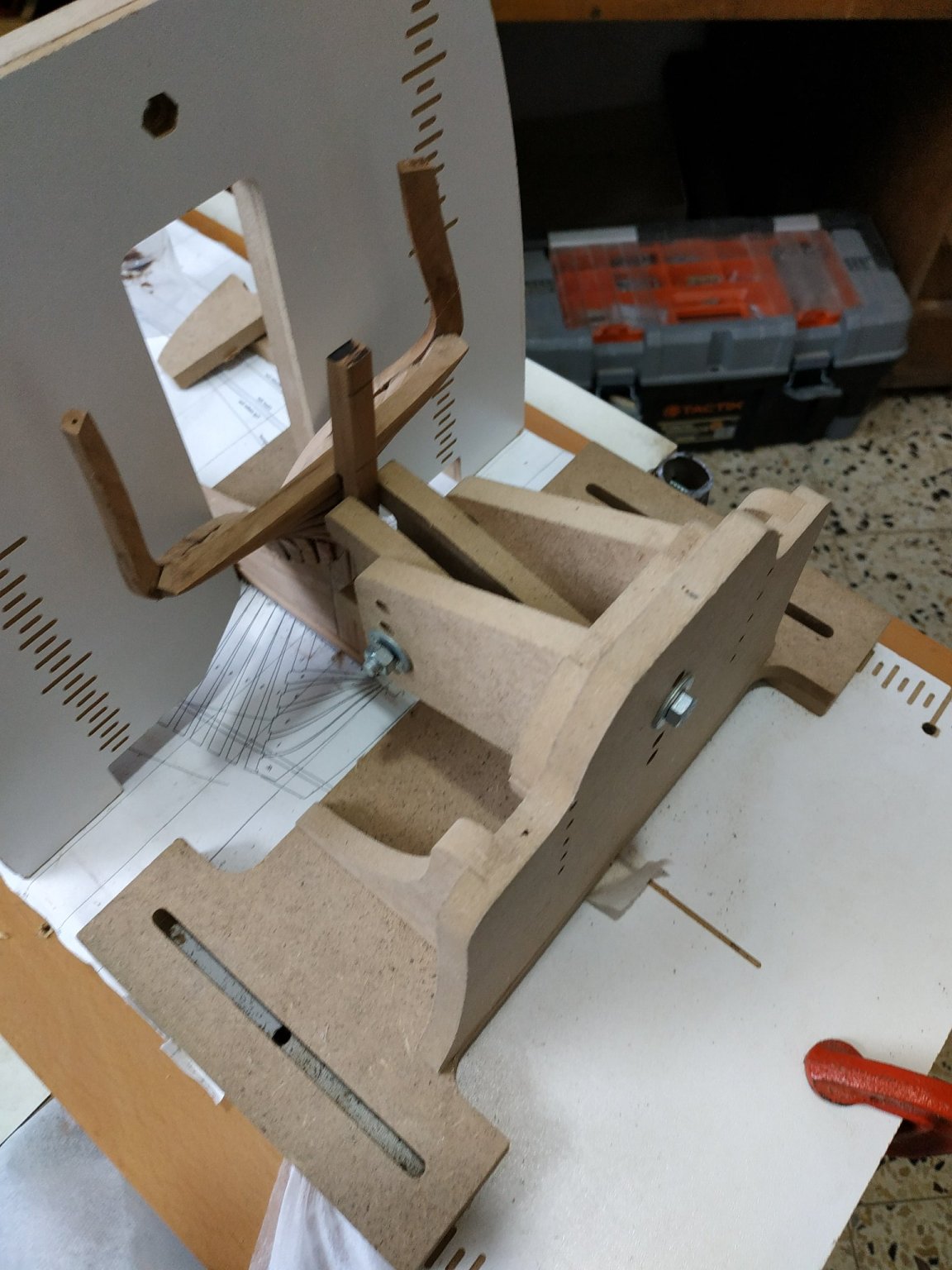
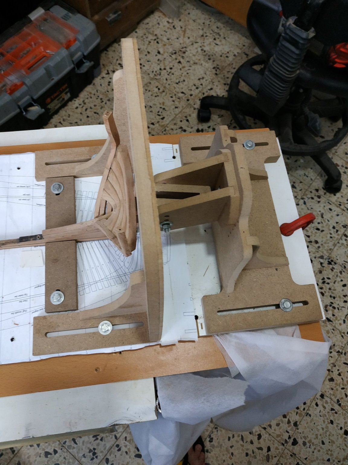
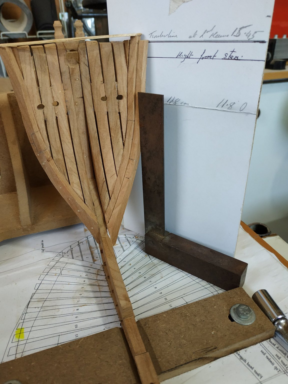
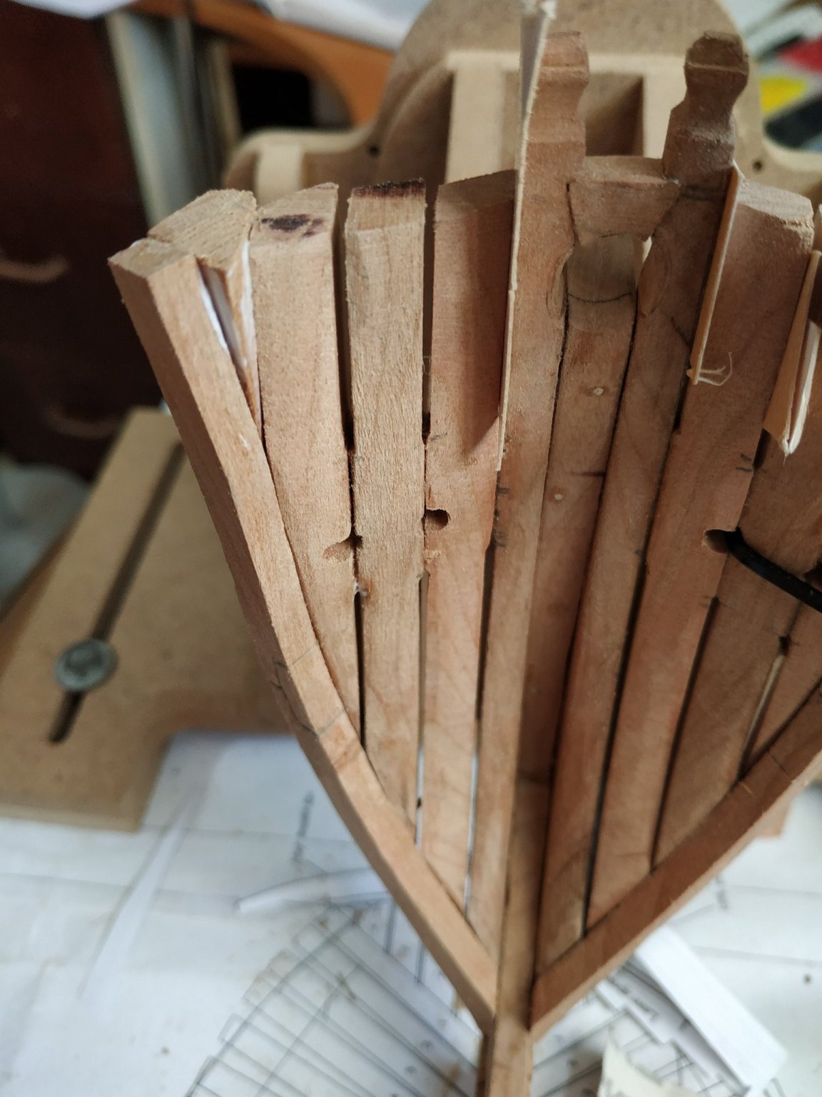
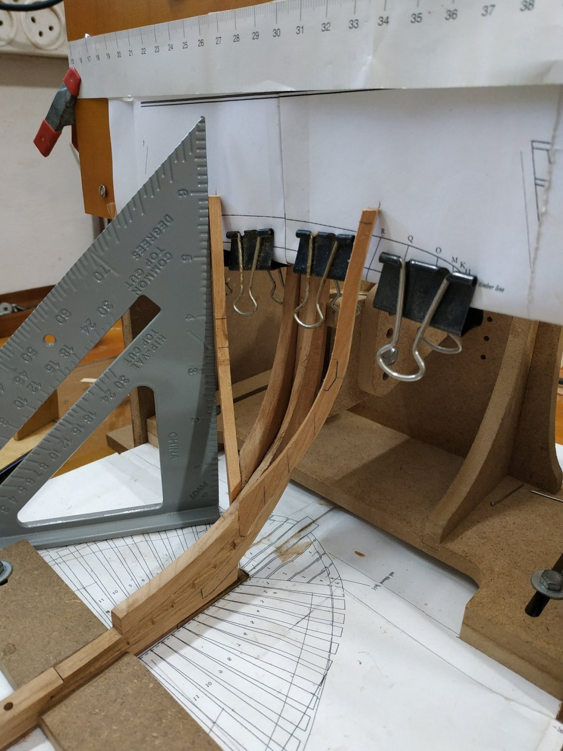
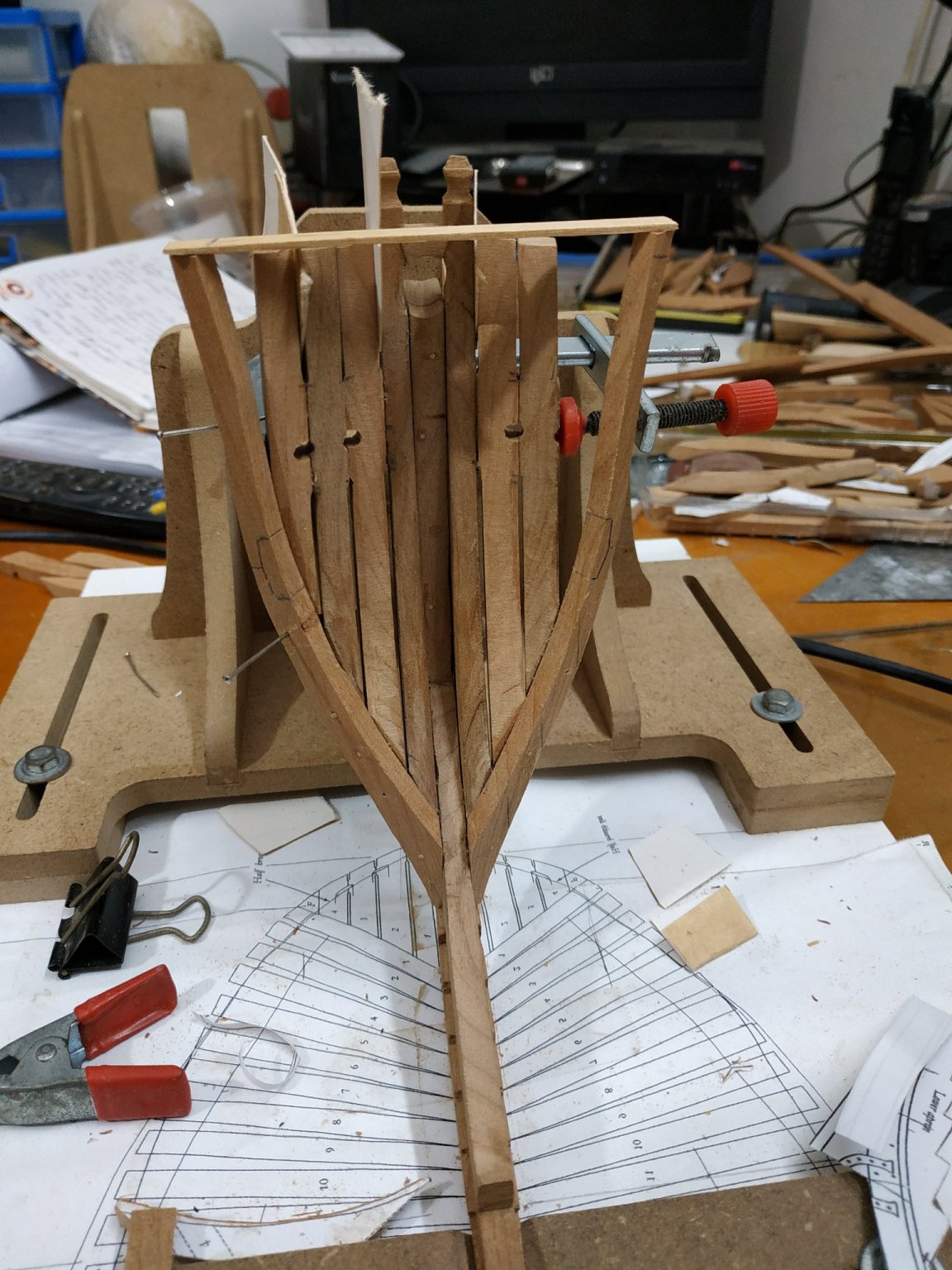
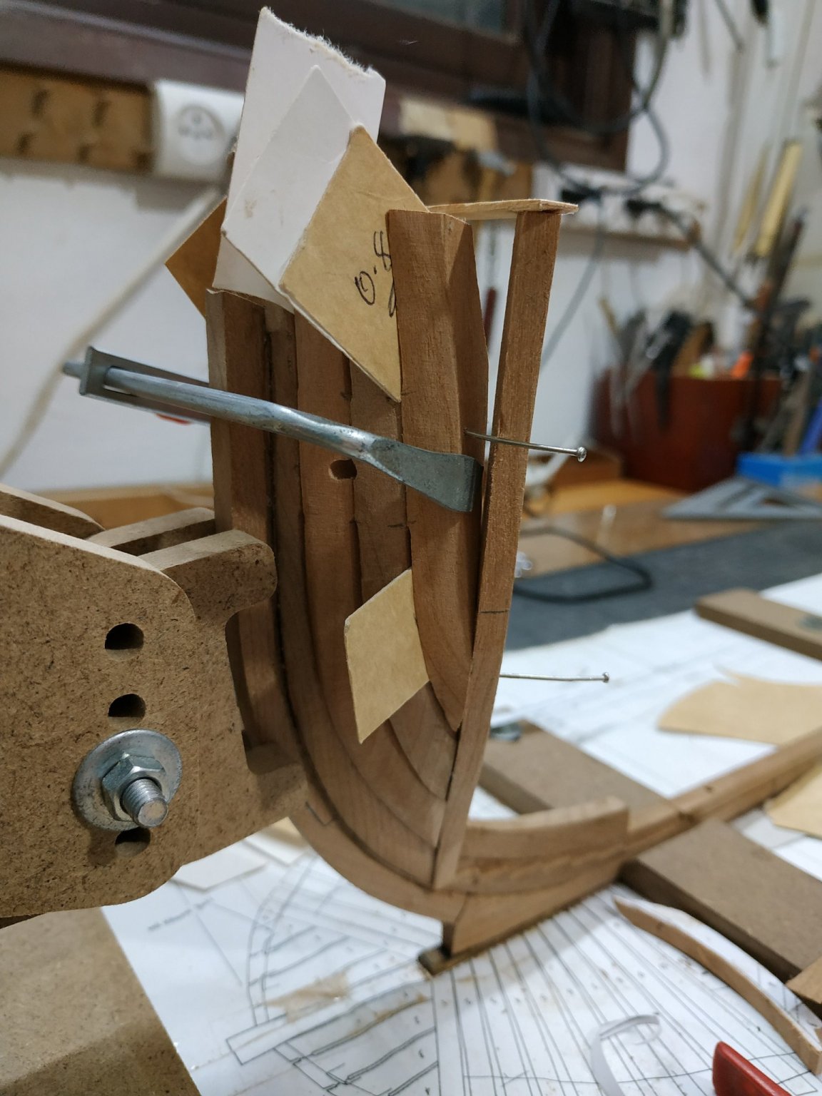
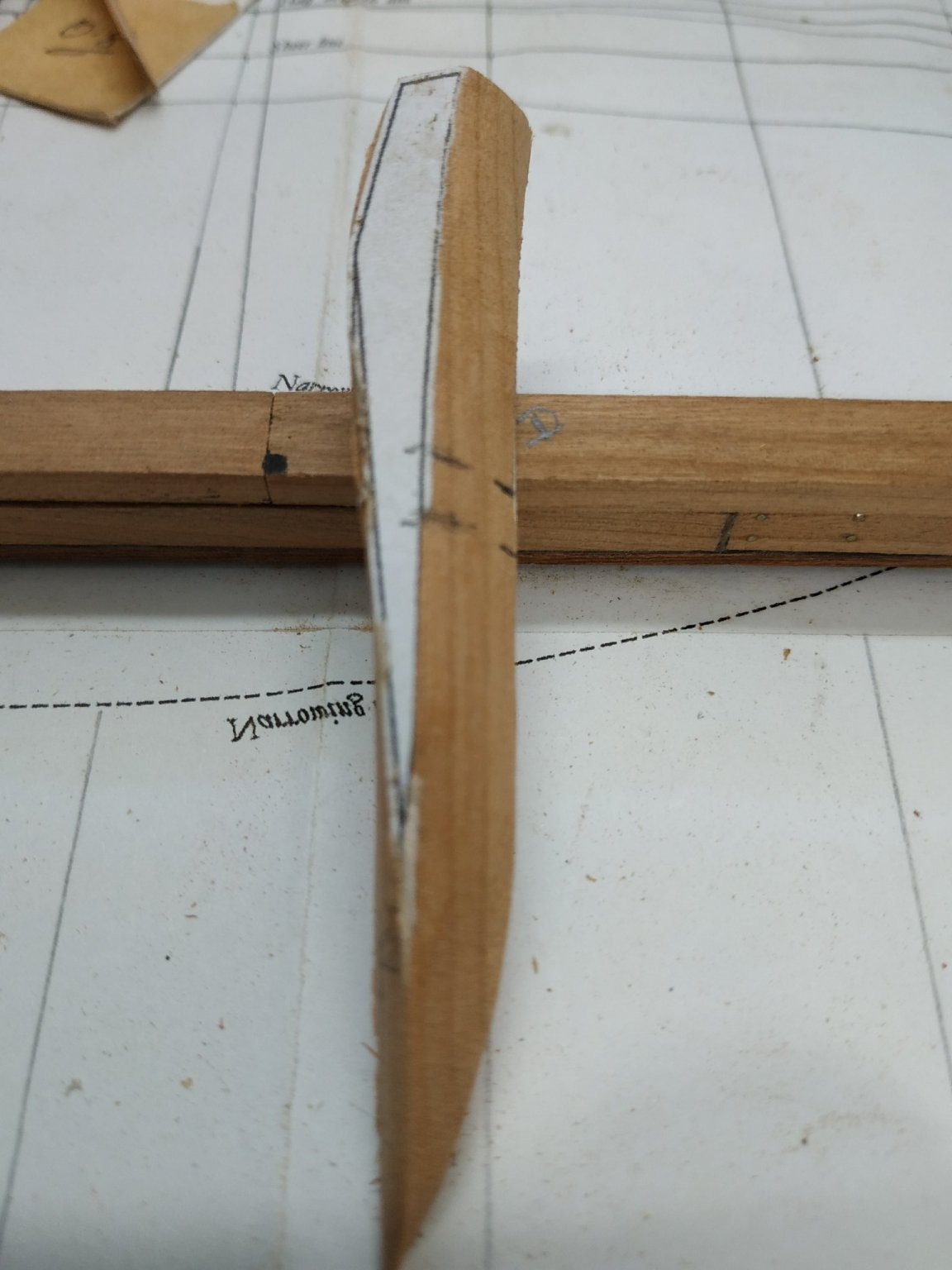
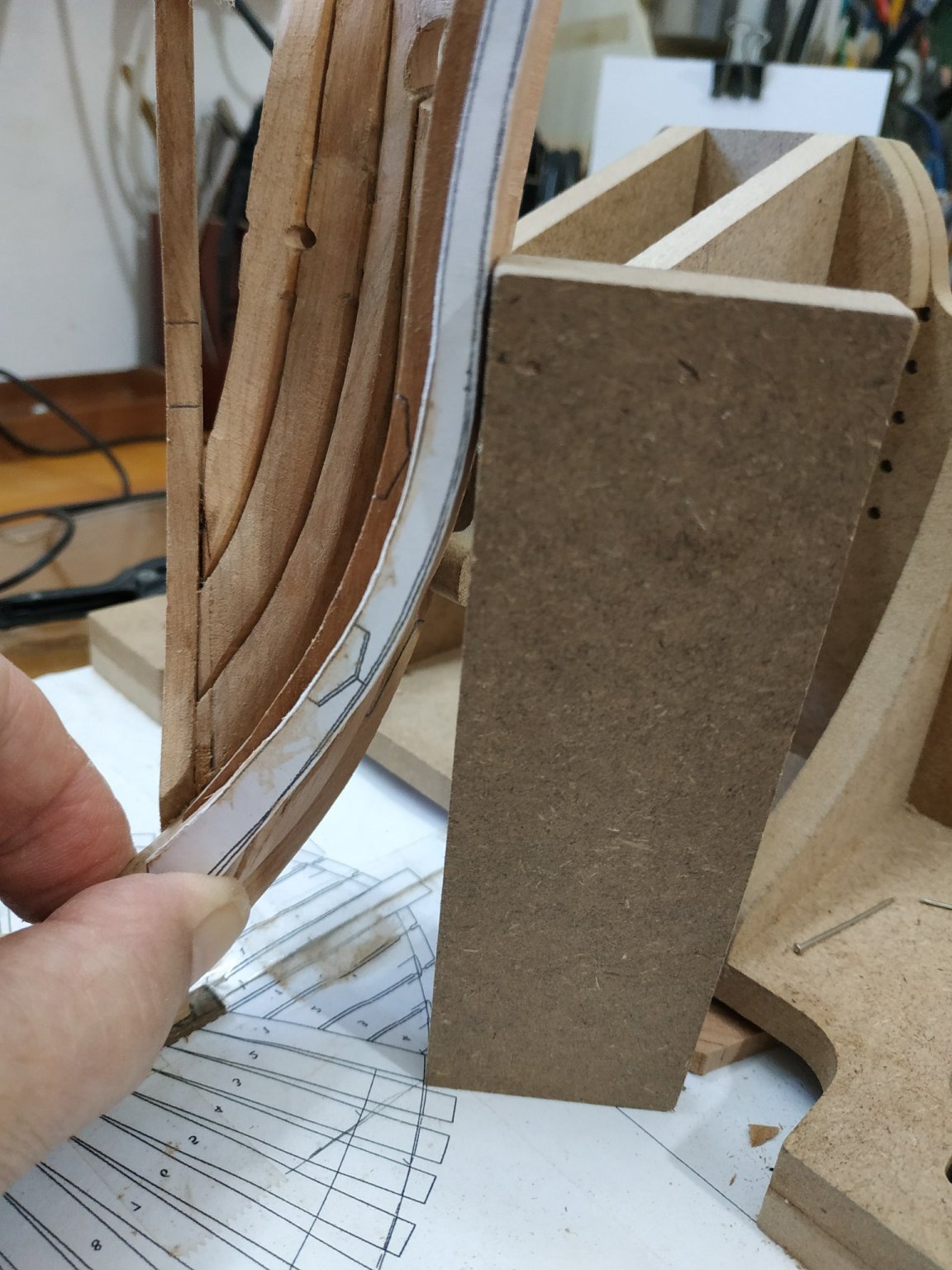
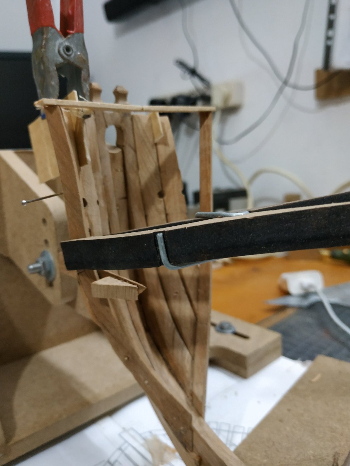
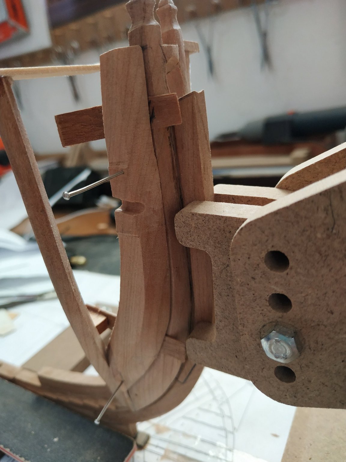
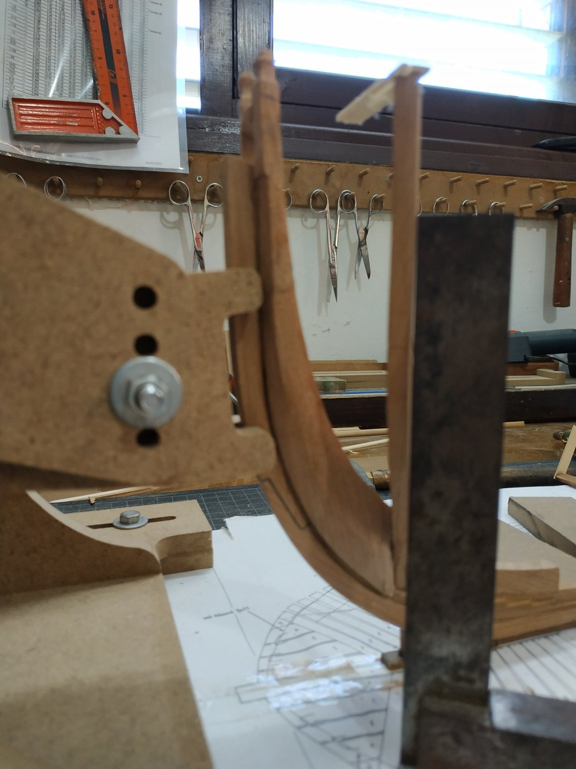
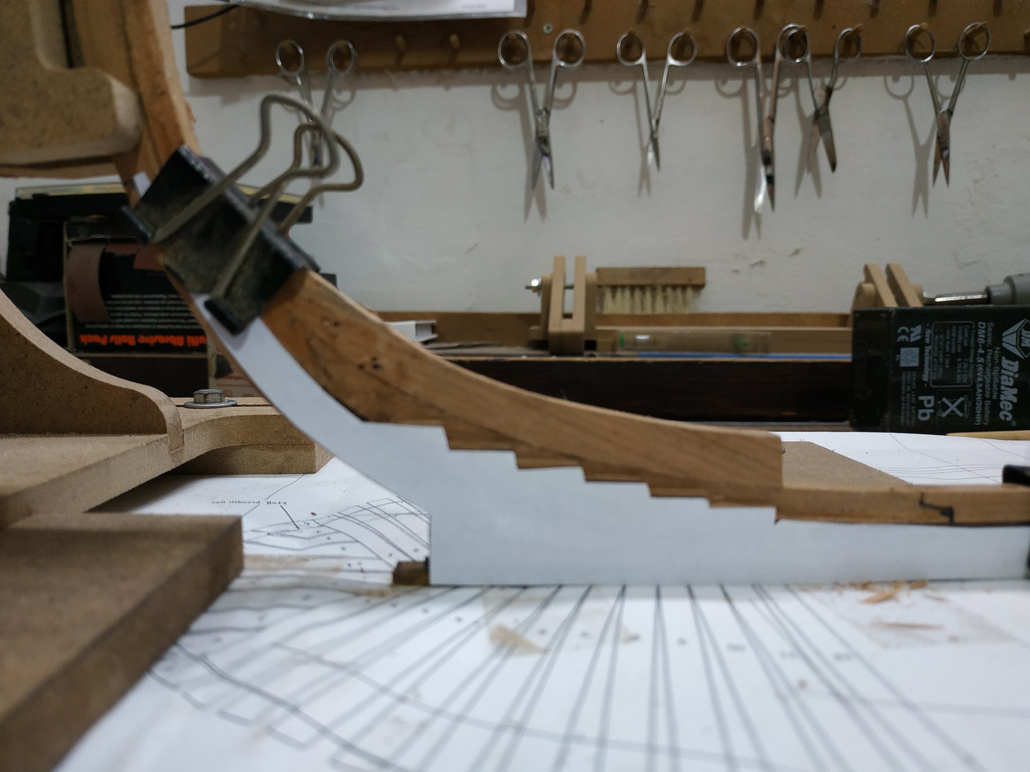
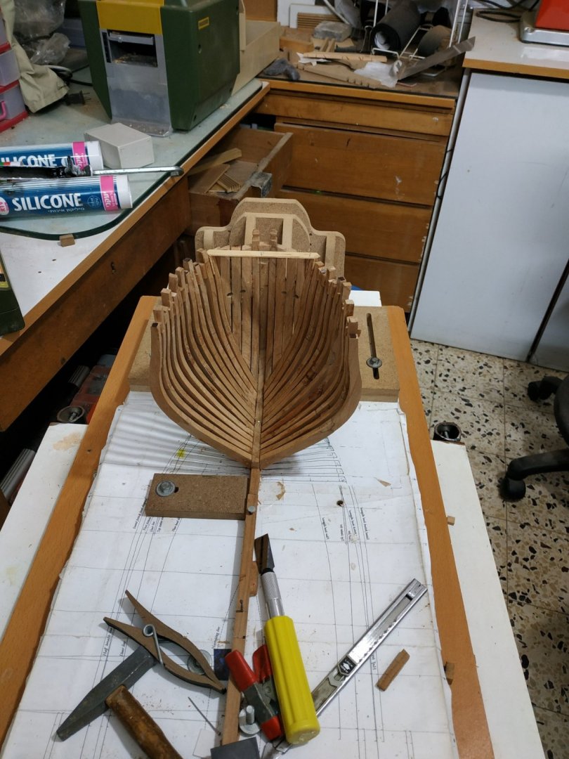
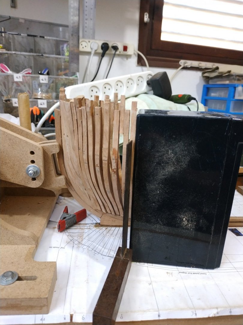
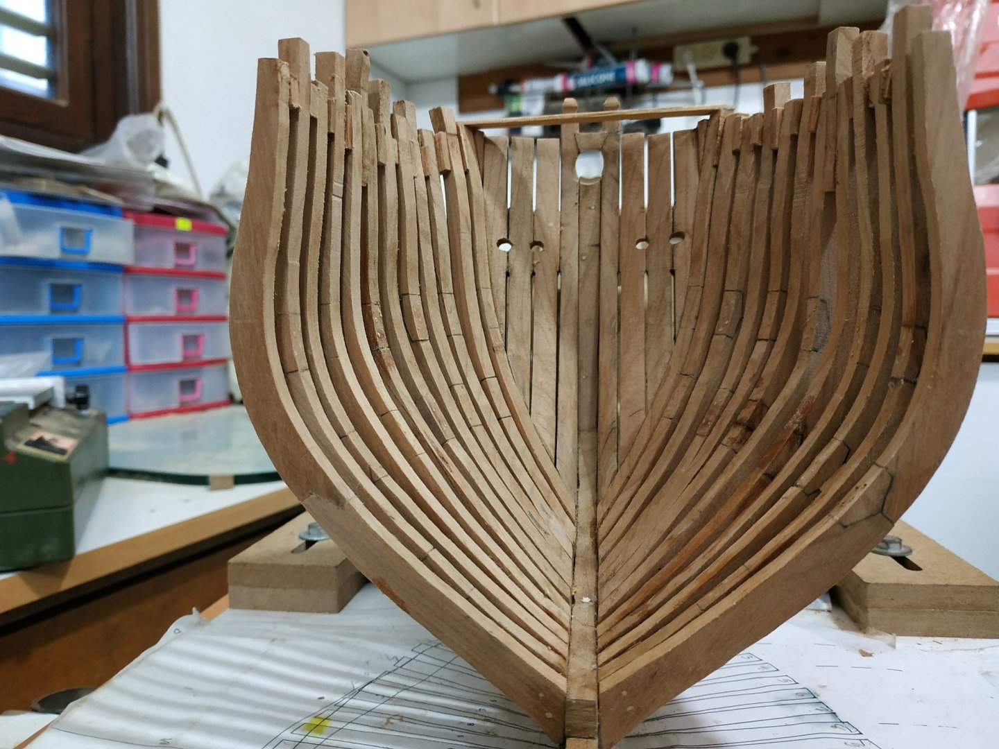
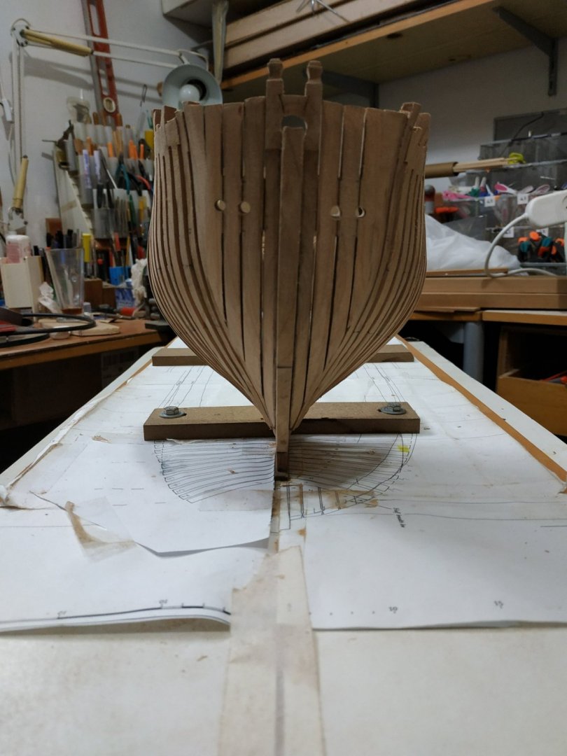
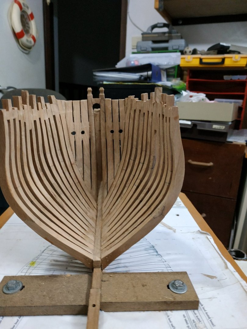
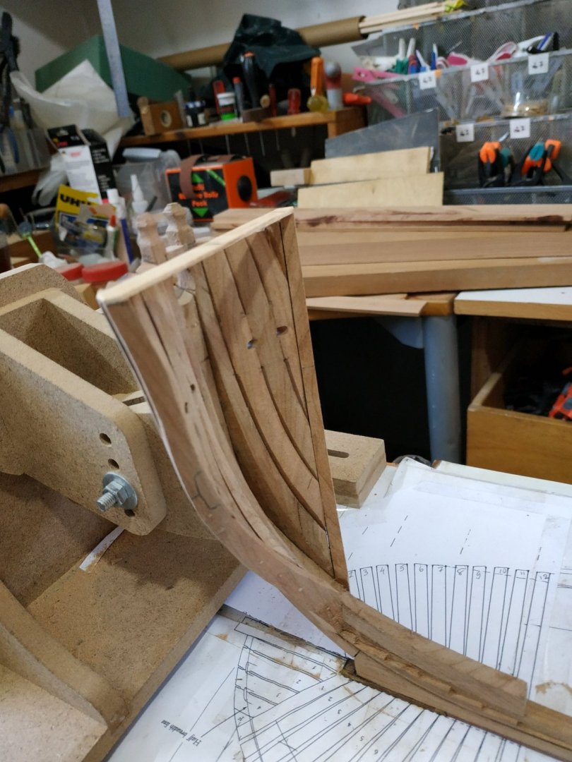
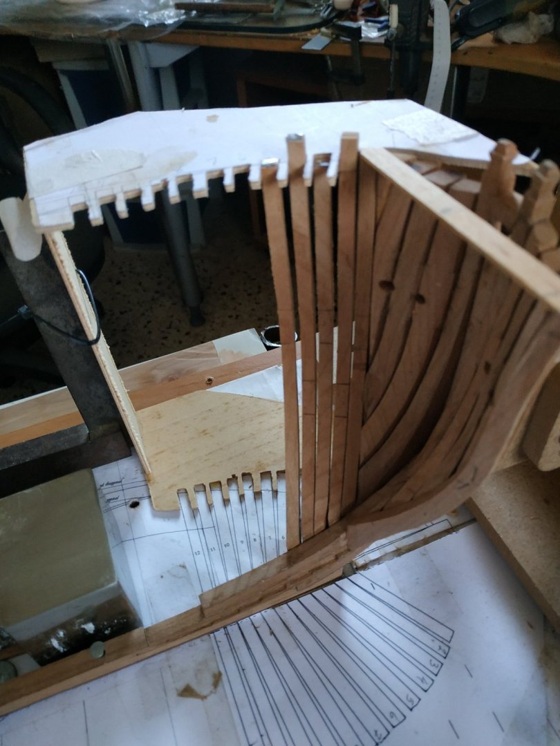
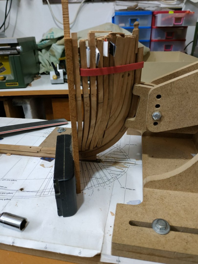
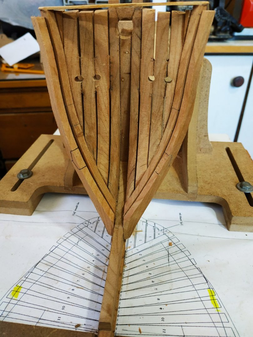
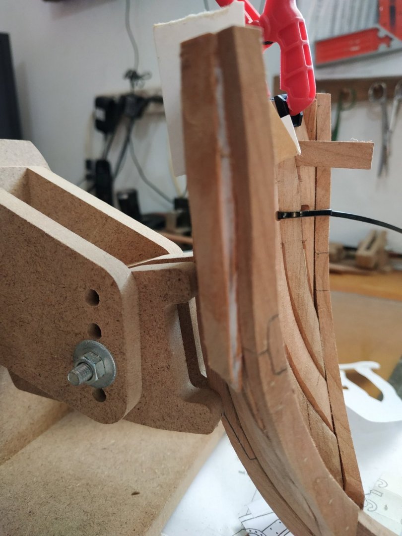
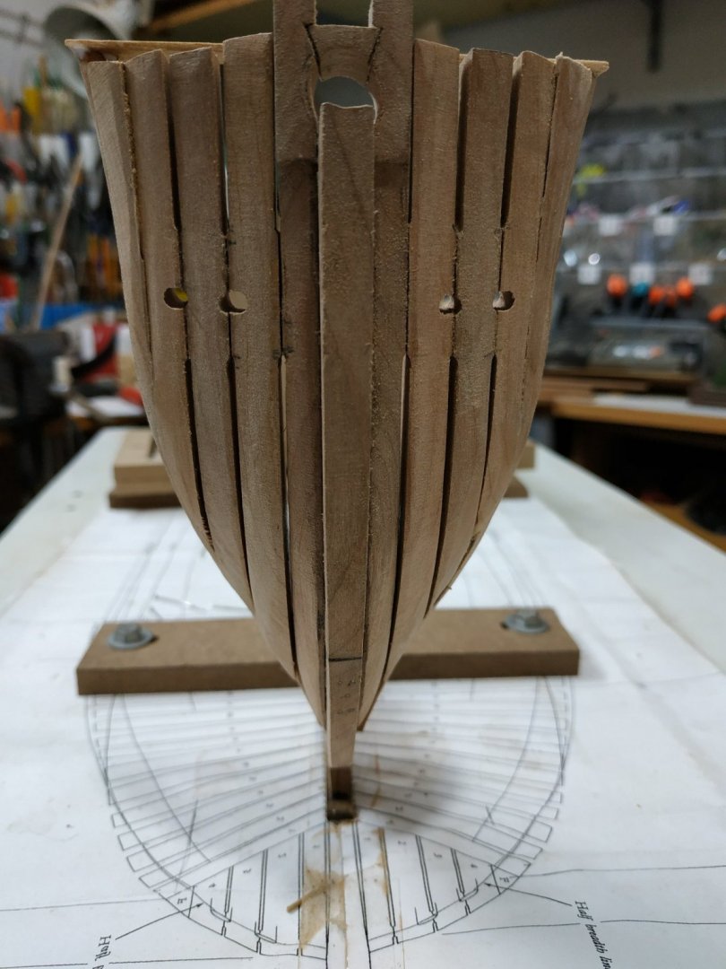
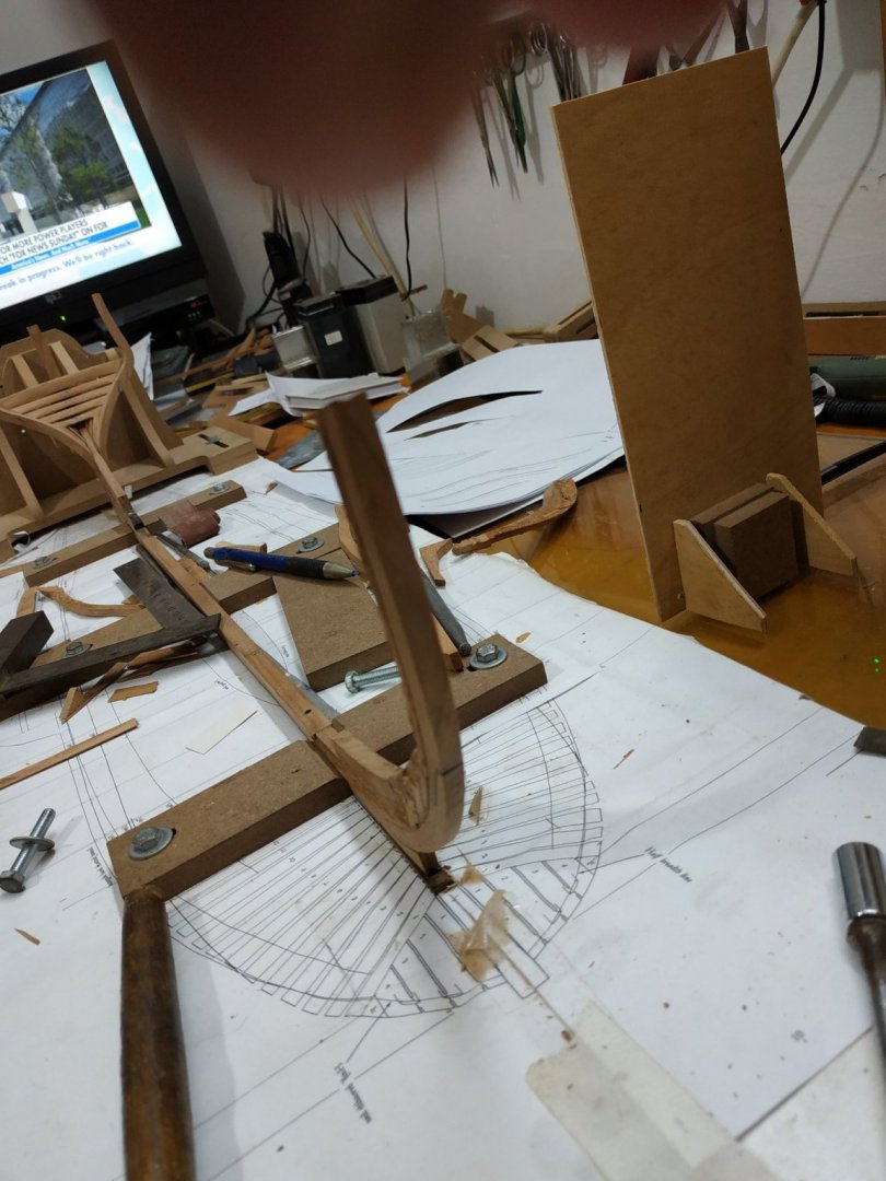
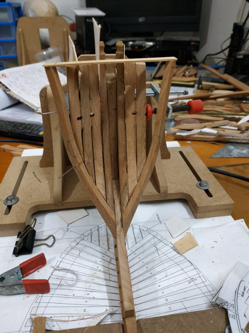
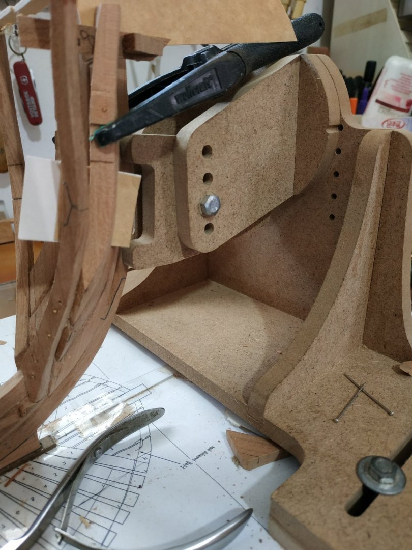
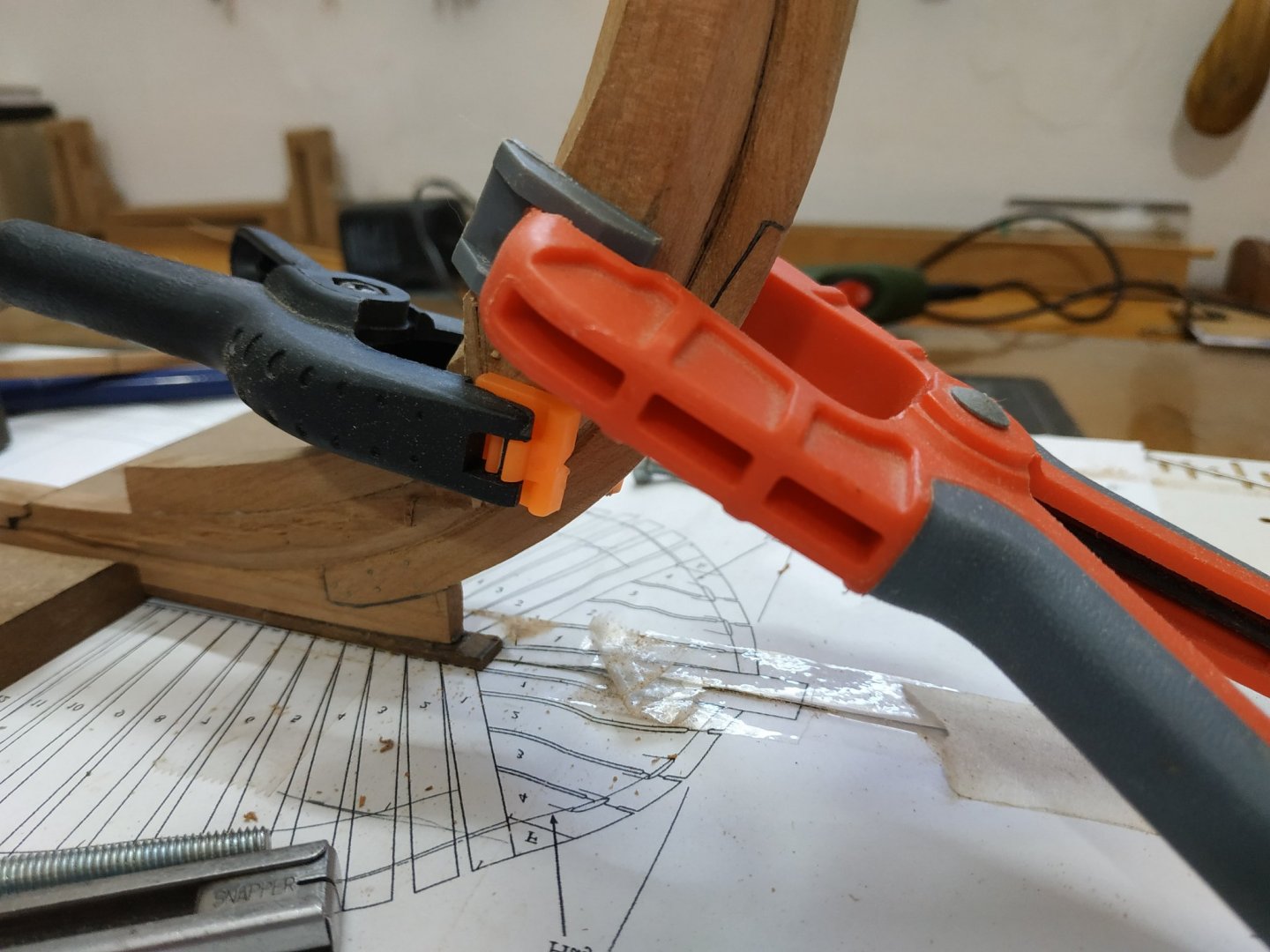
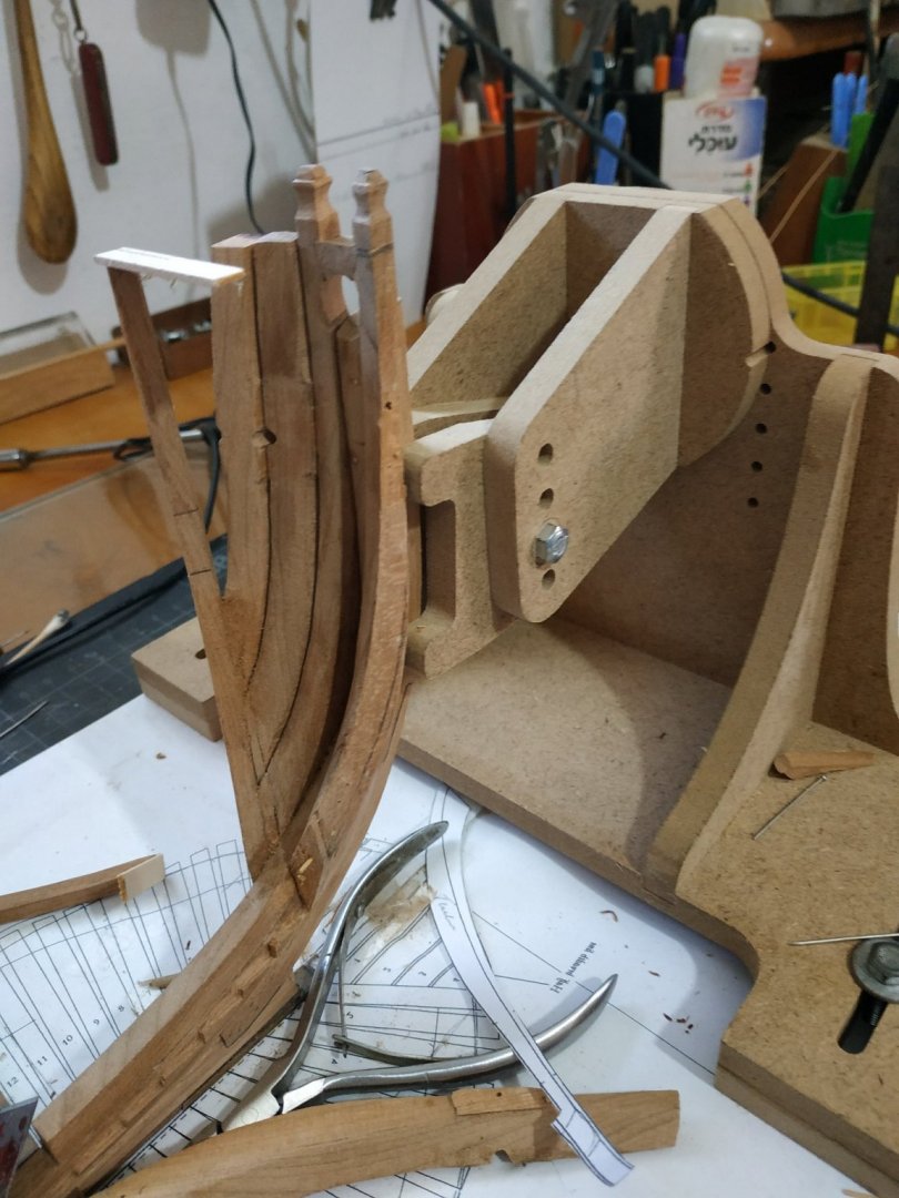
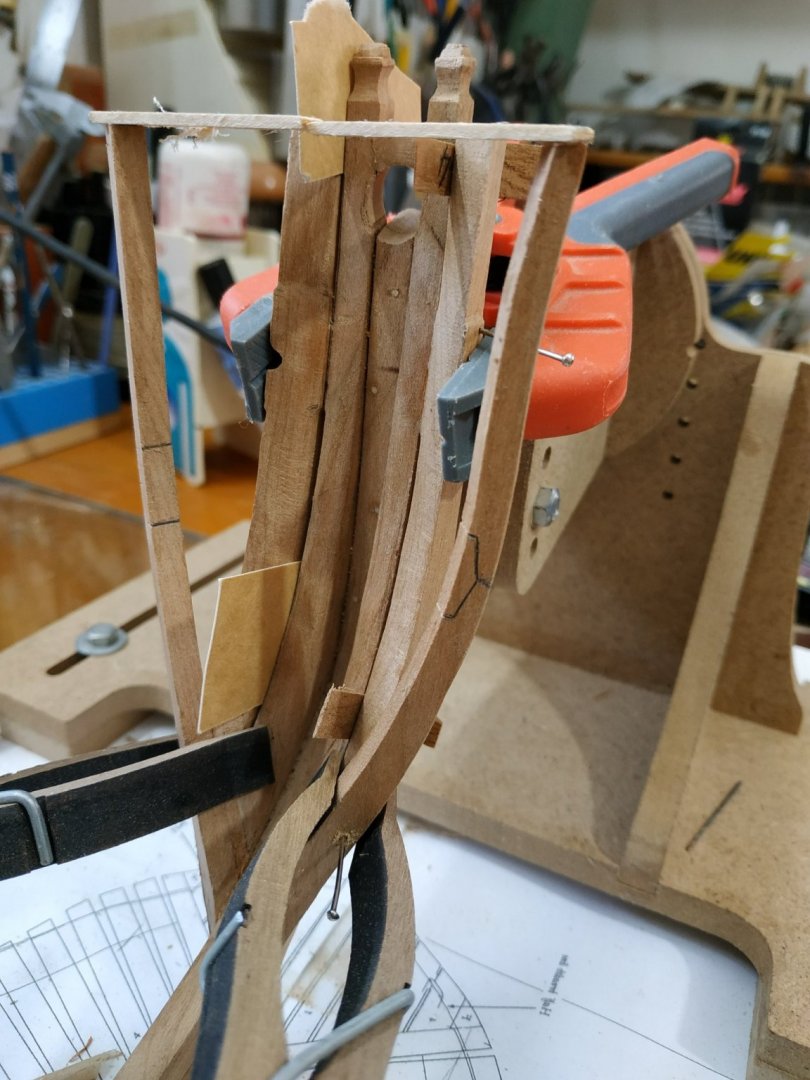
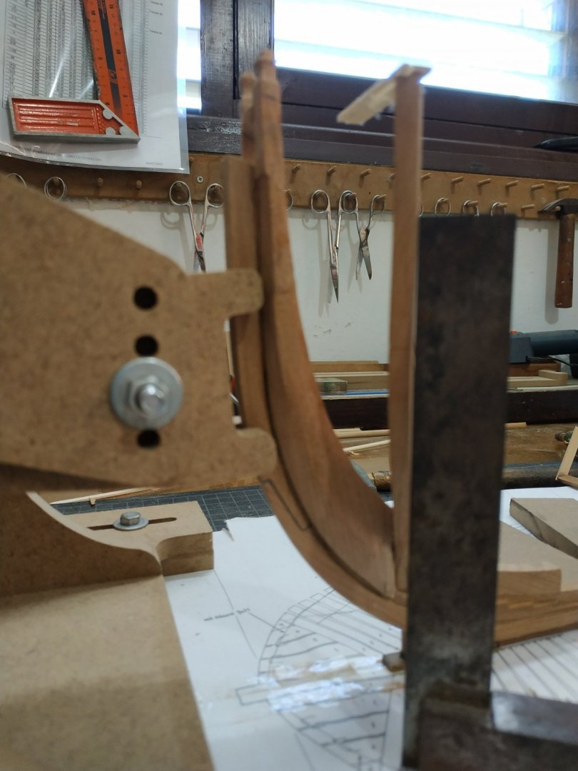
Place some crude spaces at level of timberline. Intention to remove them later, but give stability for fairing etc Not having use of thumb is somewhat restricting. The jig reused upside down for the starboard side seemed to work ok when reset (what was the straight floor, now is sloping at timberline level) with some weights. When the full set of cants fitted, jig removed and the result is not as good as expected. The main problem seems to be the angle where the timber parts are glued. I removed a couple of the worst offenders and checked them against the printed outlines-not so easy as they obscure the plan, and the cut outs can be distorted. Opening them and re gluing made some improvement, but “gradient” between the cants, seemed excessively uneven. Decided to remove all cants #2to#12 and check and realign joints between timbers as required.Extending lines on the plans help this alignment. Placed each cant in turn,checked alignment at timberline and “step” to previous(neighbouring) cant, and if still too uneven, modified the angle at the join slightly. (the black square object is one of many old batteries I’ve collected over the years-stable,heavy and reliable rt. angle.) This time the result is much better. Fairing by hand. Wands and literally by hand on inner aspect ( a broken belt sander-stiff). Much to remove but this cherry is relatively soft compared to the Pau Marfim that I used for Oneida. Left final smoothing until rest of framing complete with some internal “stiffening” Some of the small fillers separated and it would have been better to stable with a trunnel. Returned to working in clinic and less time to browse the internet, so only now caught up with Kevin’s video no. 12 and see he run into similar problems. Considering the high quality of his work, I feel less inadequate. Thank you. PS last week or two, temperatures here fluctuate . 2 days ago on the beach, today cold and torrential rain. Not good for wood or glue. PPS Happy Thanksgiving to our American friends.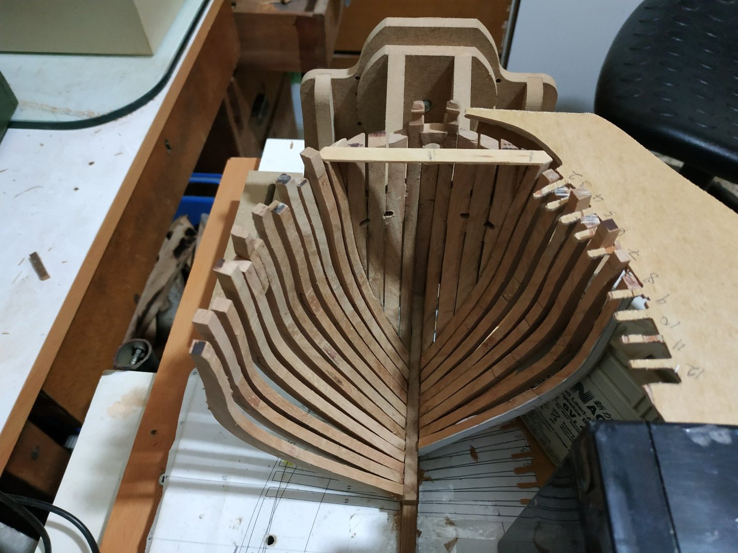


- 475 replies
-
- 12
-

-
Swan-Class Sloop by Stuglo - FINISHED - 1:48
stuglo replied to stuglo's topic in - Build logs for subjects built 1751 - 1800
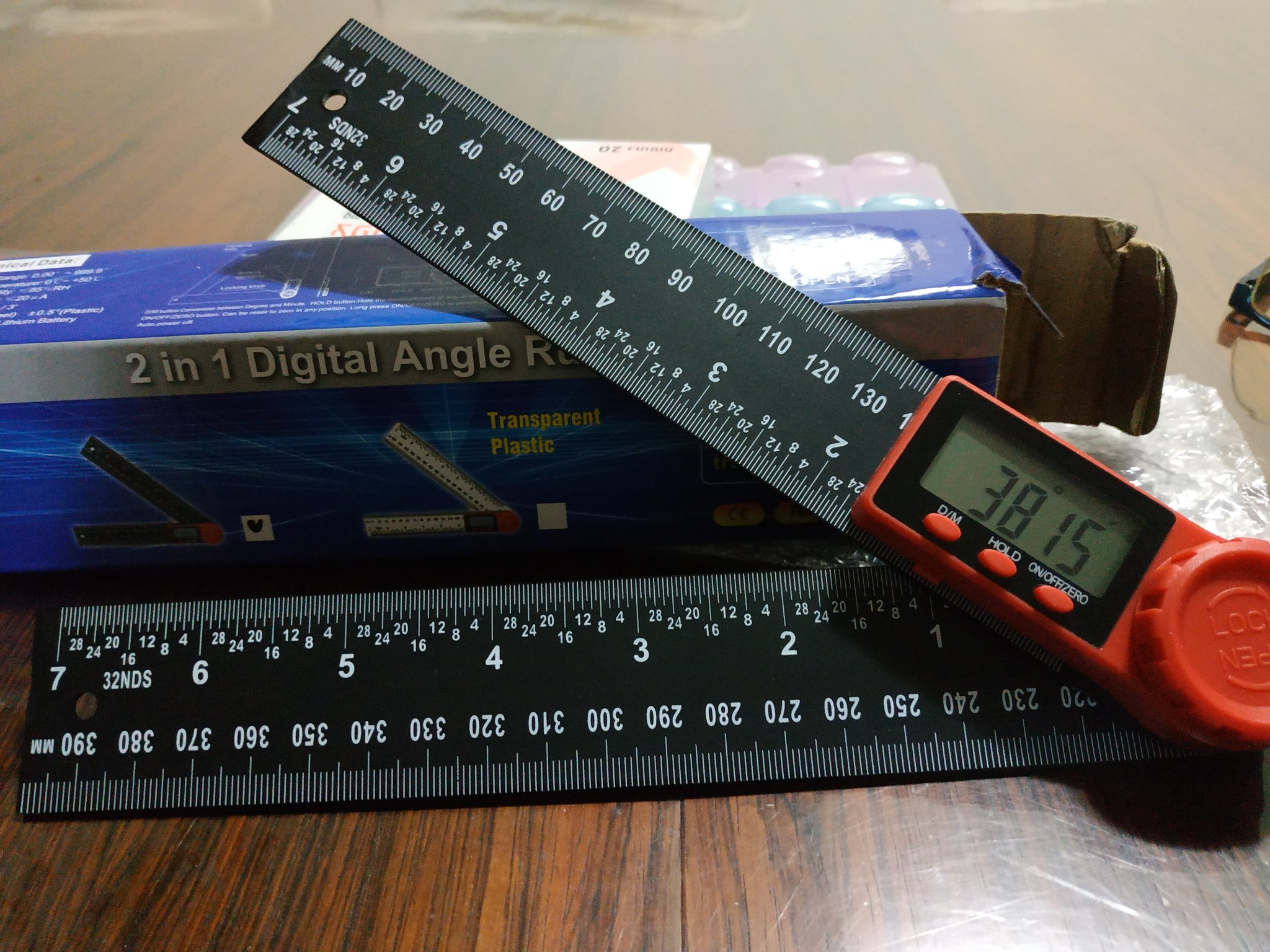
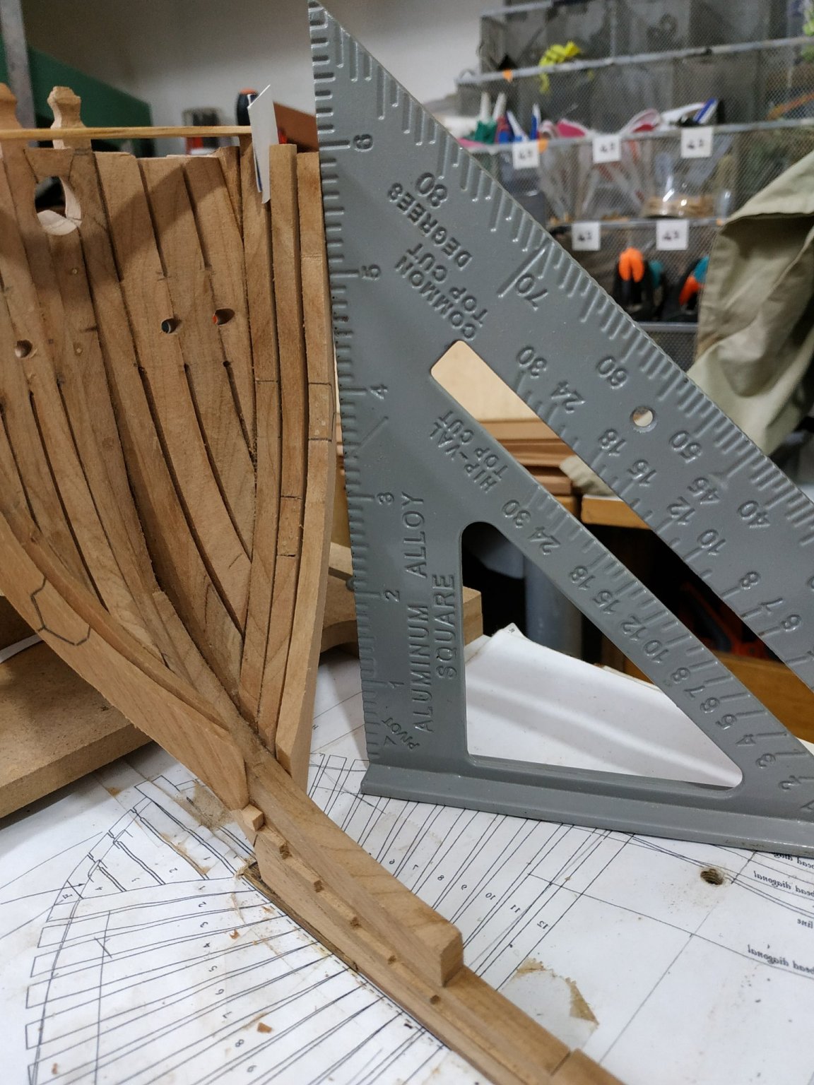
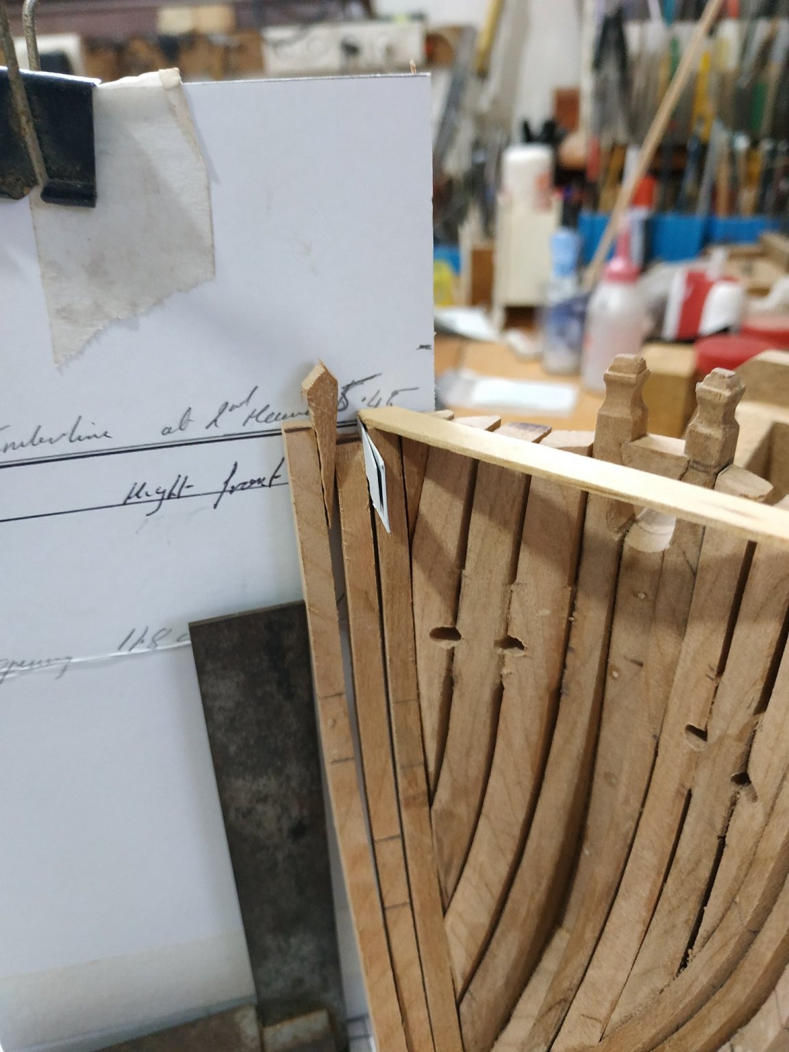
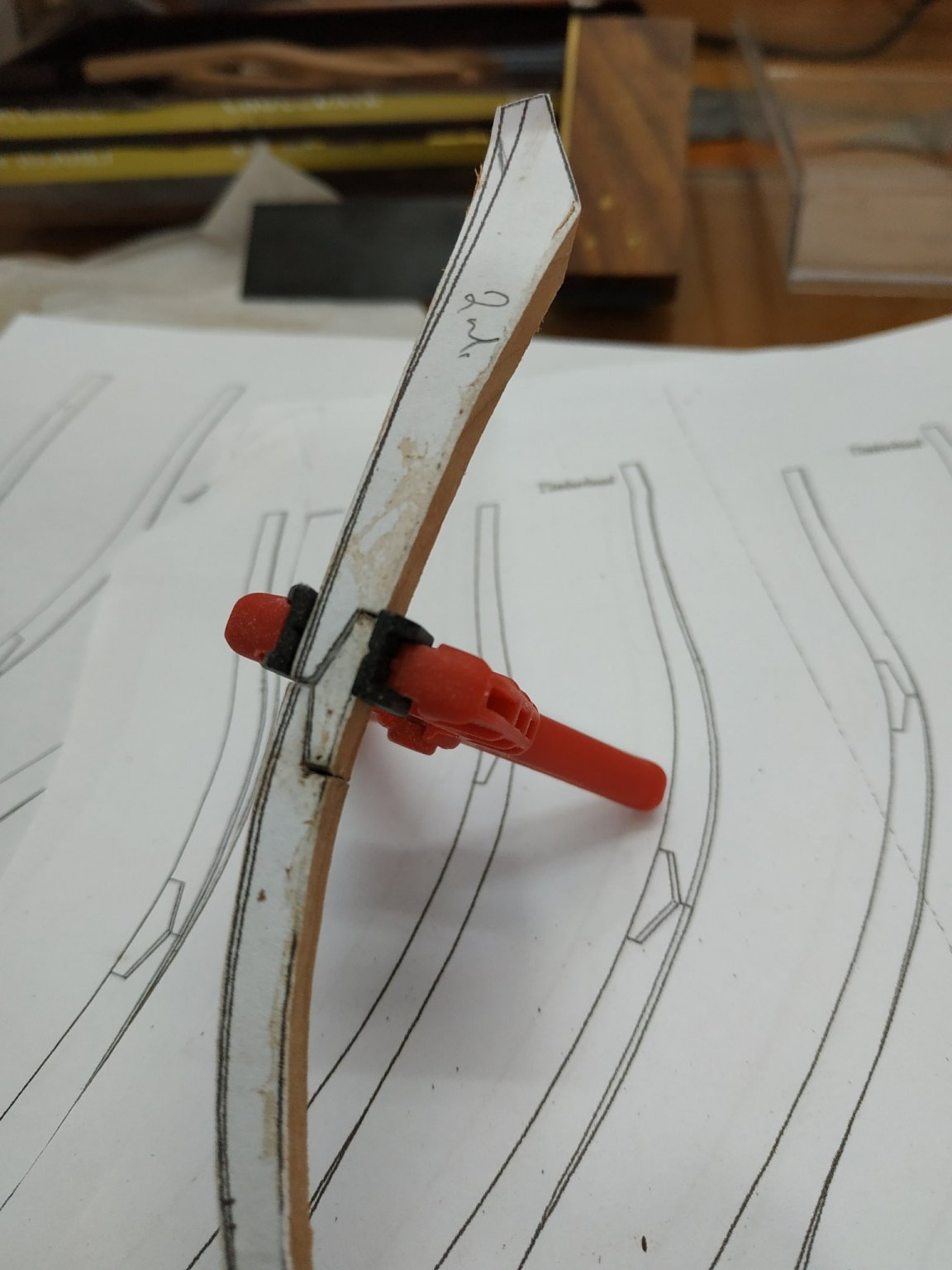
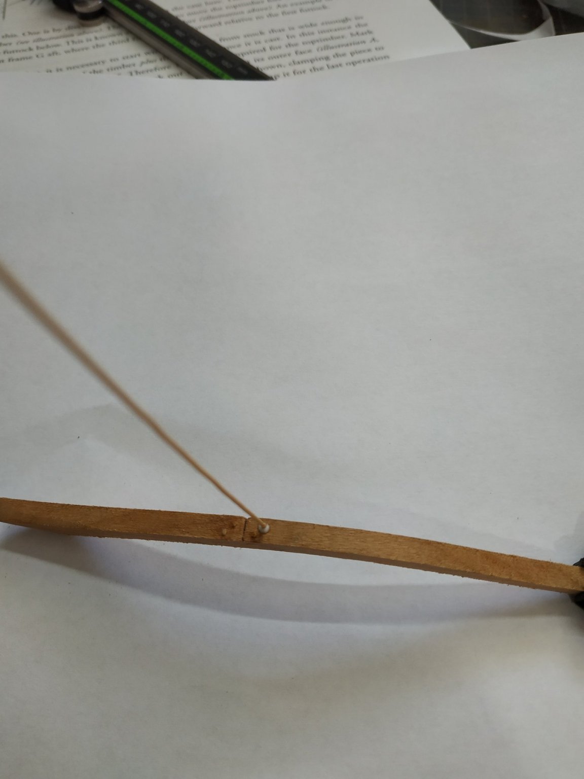
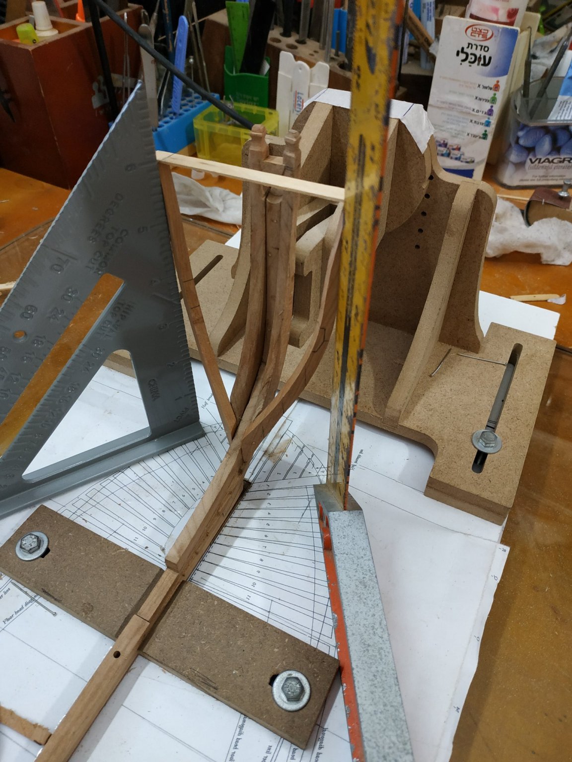
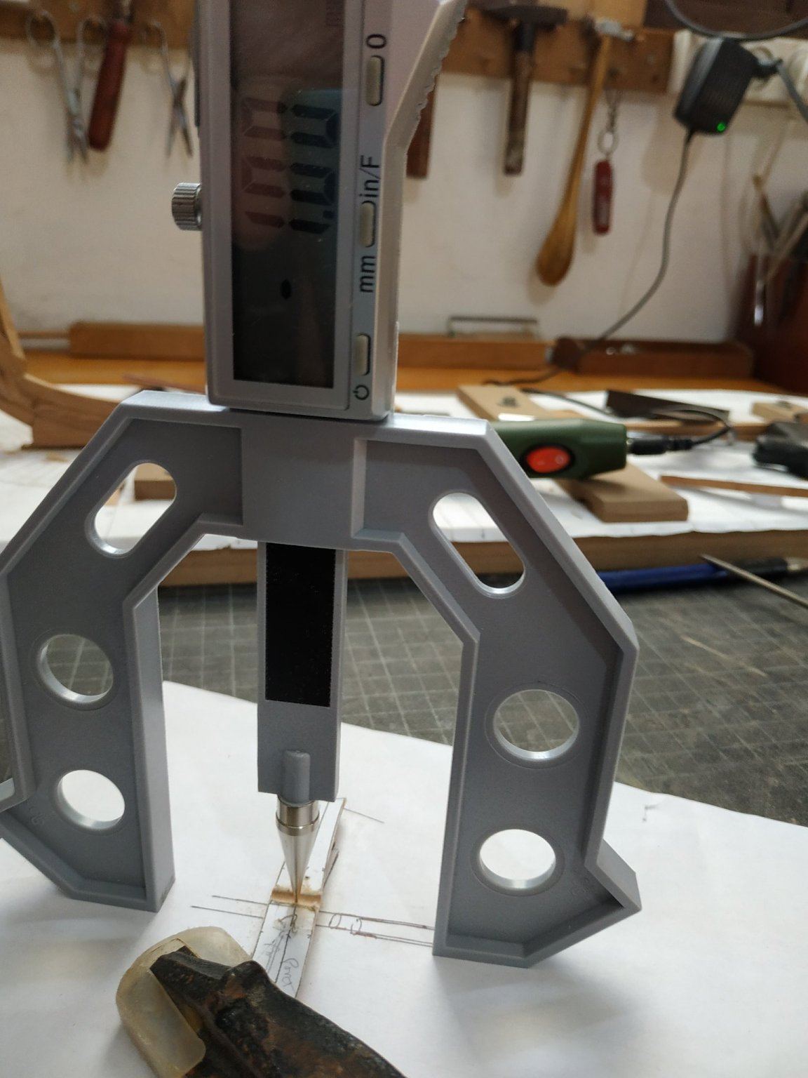
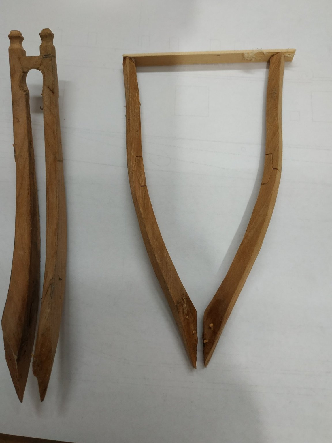
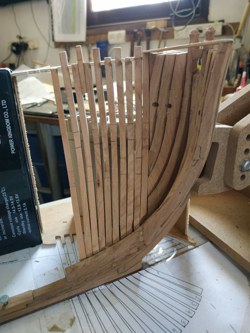
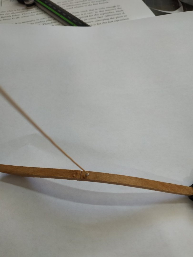
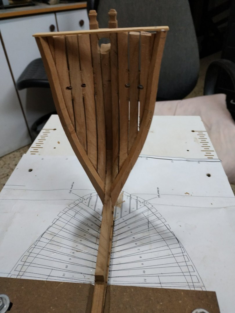
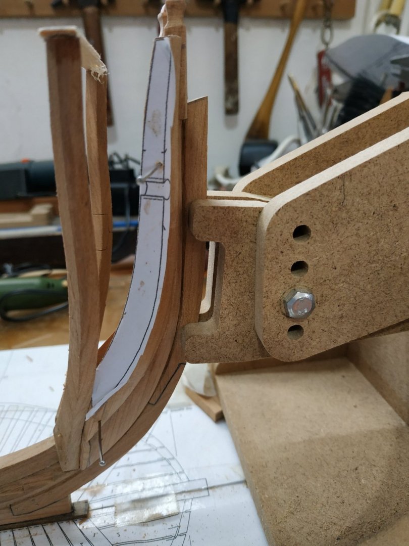
Finishing # 11: The milling (remove 1mm from each side) and transition (about 10mm) by hand -seems to work OK. Final port cant #12, 2deg bevel The jig is not rigid, therefore can be turned over and used on starboard side(with support at 90deg. and a weighted base.The “tooth”between #7and #8 needs removing and the gap for#11 needs widening (for shift). ? Did I mention that I made the cants as pairs, port and starboard, together . Also reminder to trunnel the “feet” of the cants. One into keel and other into neighbour. You’ll note that the final effort looks rough, with plenty of work for “fairing”.But this cherry is soft and I hope that the final effect will be acceptable. .The last picture is my new digital angle measure. Accurate angles are essential and my old plastic protractor has its problems.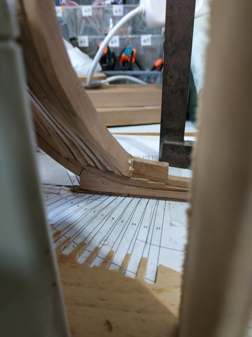


-
Swan-Class Sloop by Stuglo - FINISHED - 1:48
stuglo replied to stuglo's topic in - Build logs for subjects built 1751 - 1800
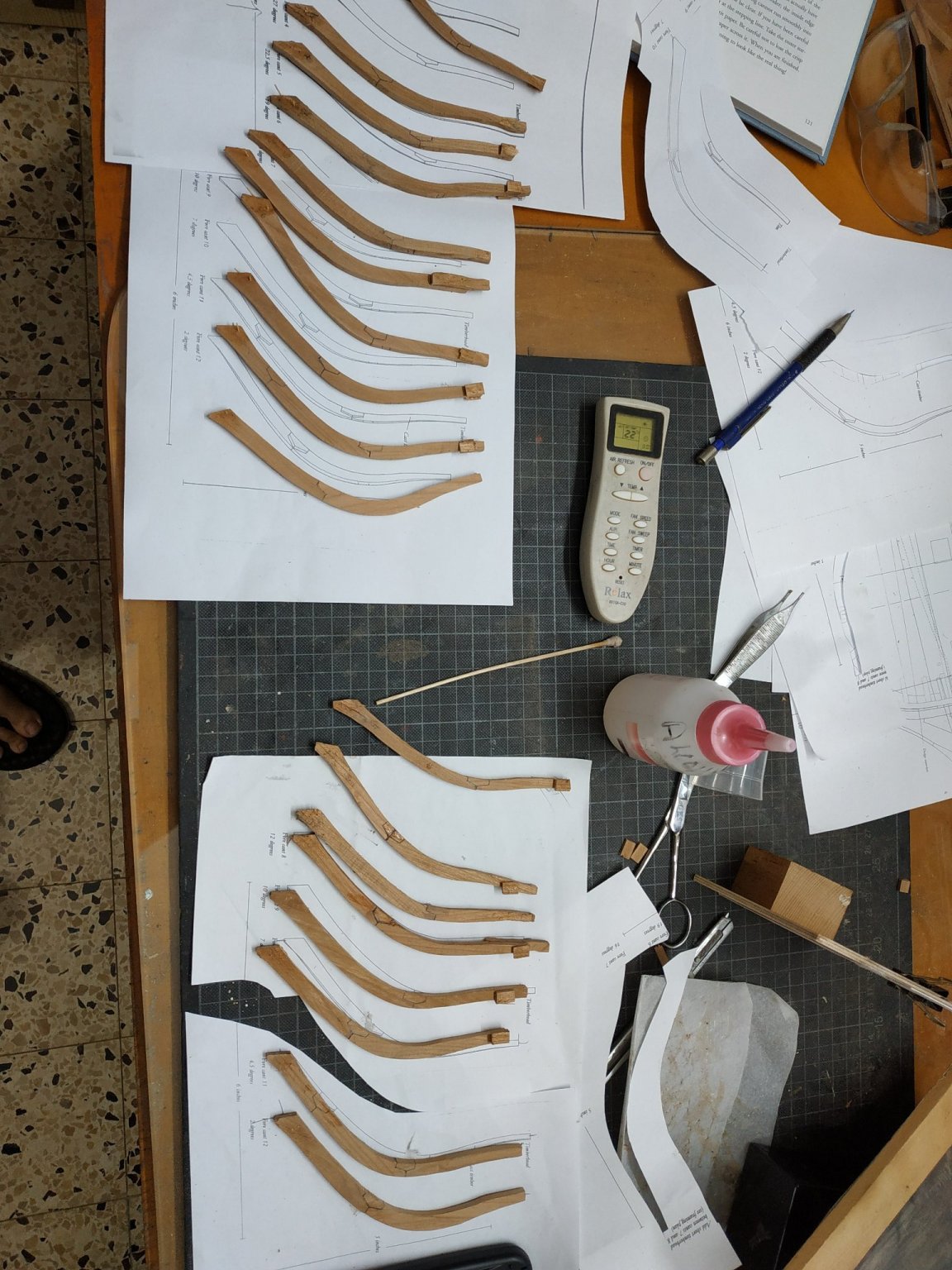
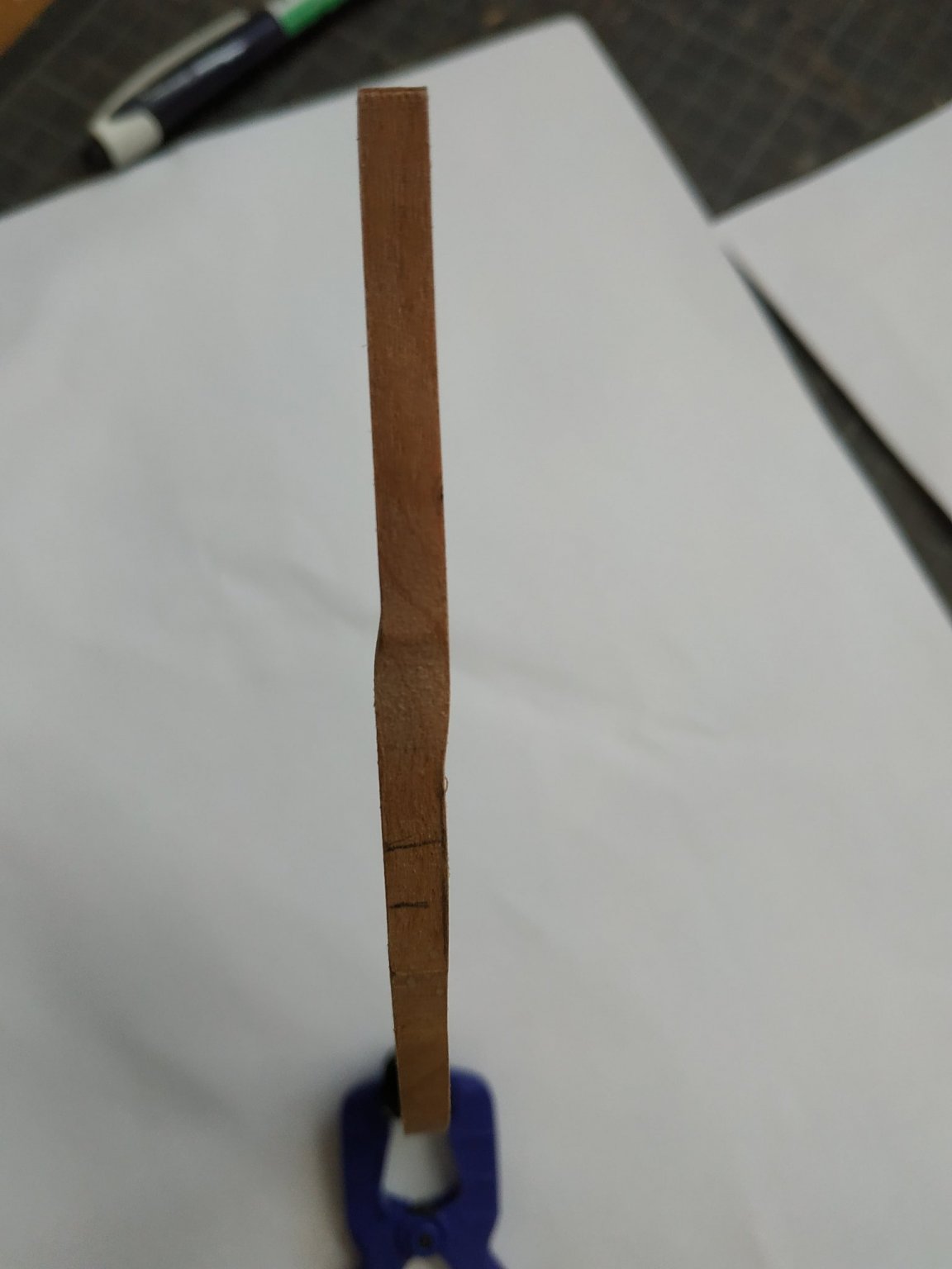
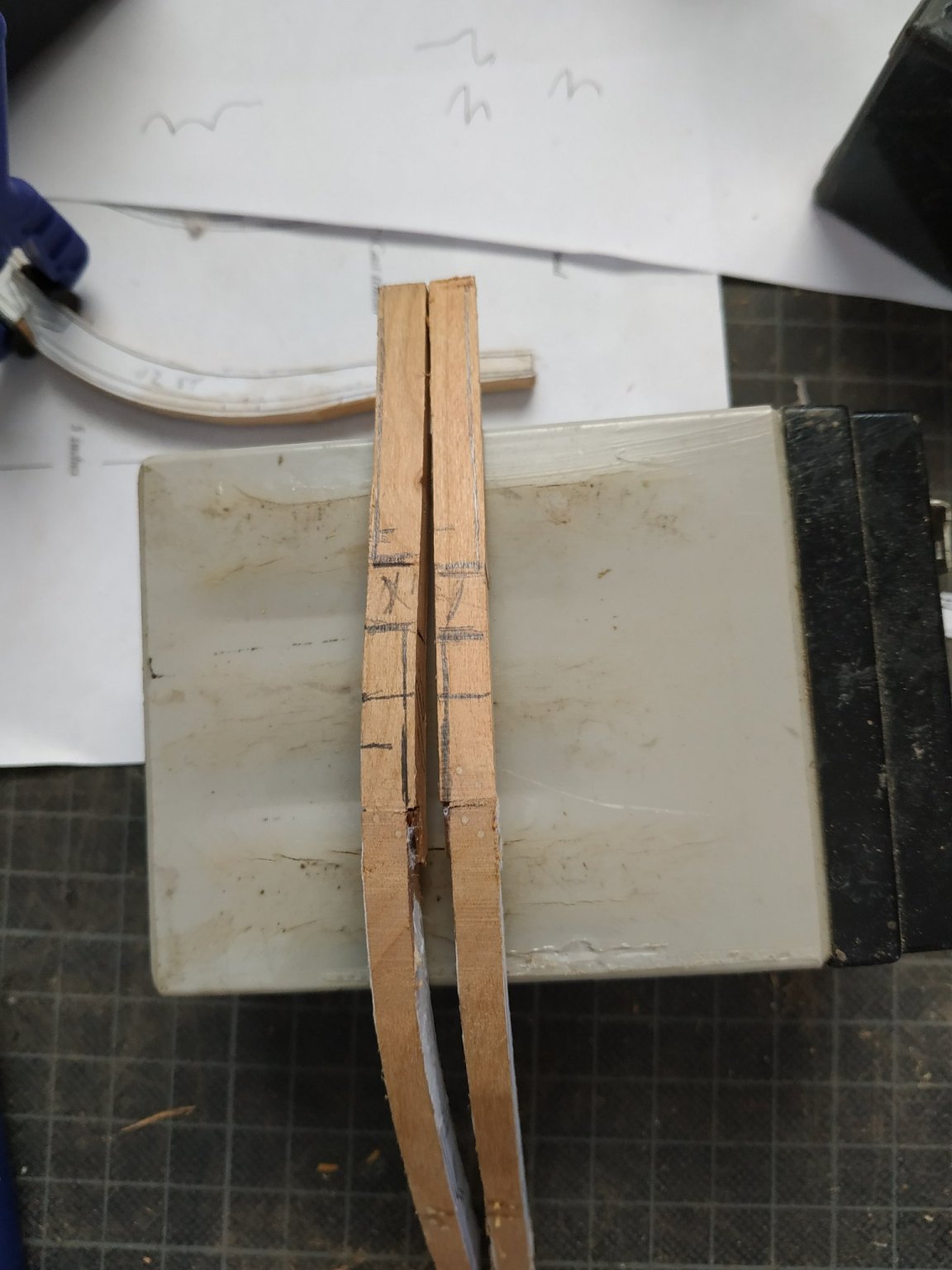
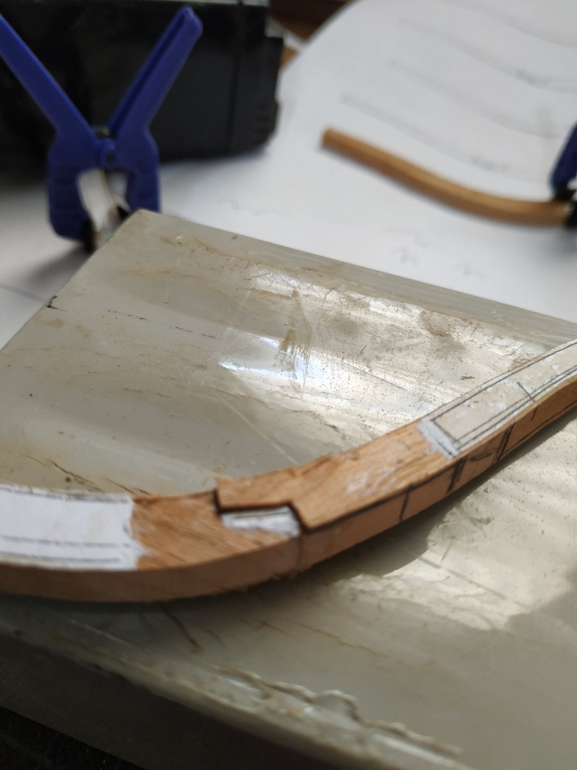
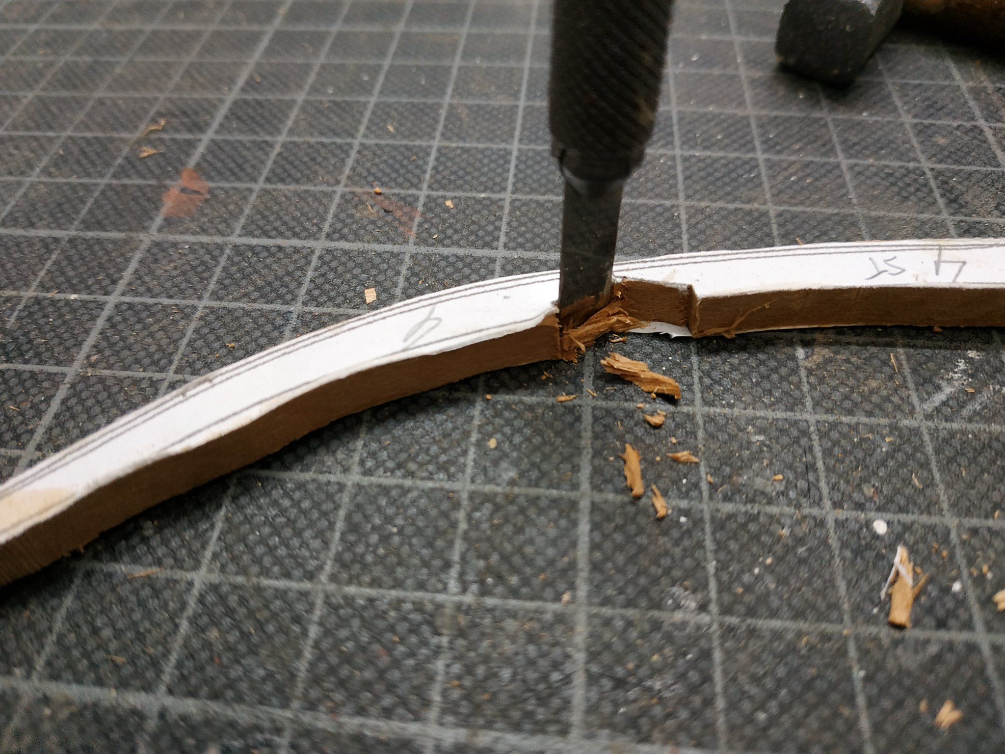
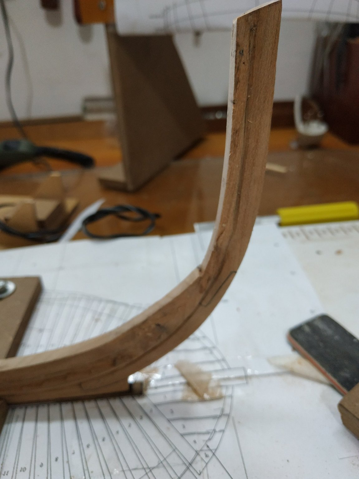
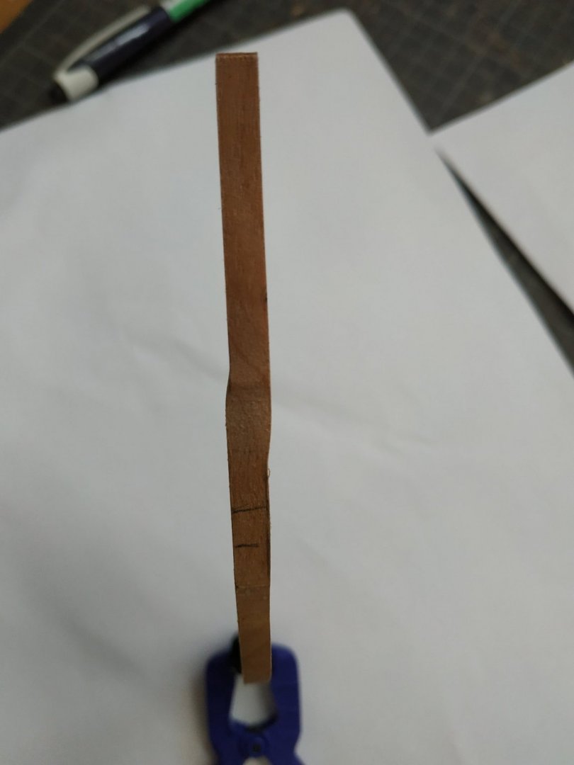
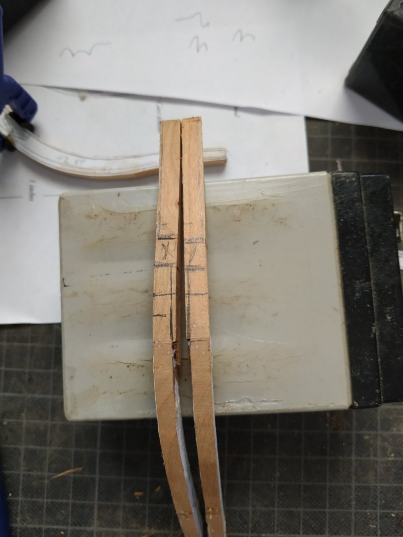
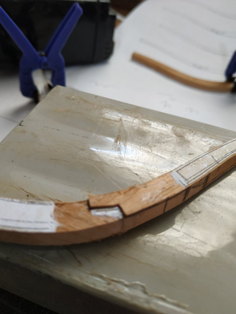
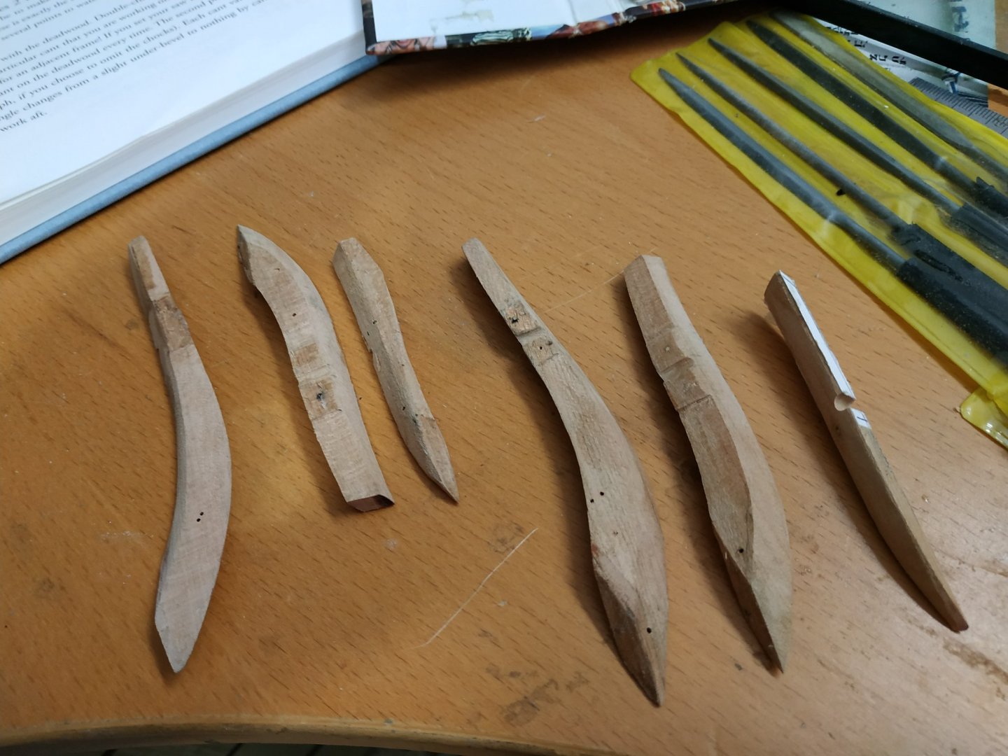
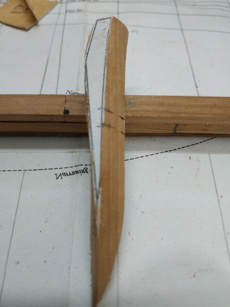
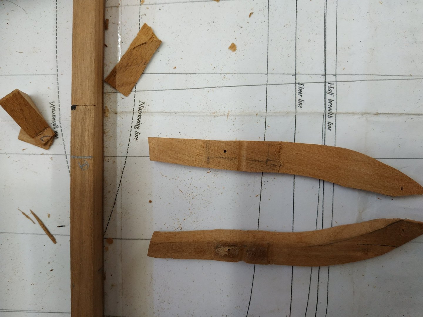
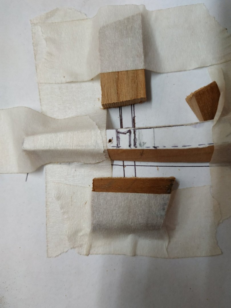
No longer a daily blog. Of course only having one and a half functioning hands doesn’t improve efficiency. My wife says this isn’t a race-and she is,of course correct,but I like to get things done. There is an English expression “all fingers and thumbs” meaning clumsiness, but a non-participating thumb is worse! Can’t help reflecting and comparing the time it takes building a scratch, framed model (and the tools and wood required) against a bulkhead kit. After 20+ models, I thought I could estimate build times. I planned the swan at 12 or 18 months (with or without masting and rigging). I must now double this , and certainly not contemplate a parallel build. I think I mentioned that I will leave the lower (foot) bevels to later fairing. The first few I did seem to remove too much. The jig seems to work well.Even though TFFM says the cants 8 to 12 are aligned to the half breadth line,they will also (it seems to me)follow the top timberline -but note this is “inside” the “ends”of the cants as shown on the plans. Cant #8 has bevel 12deg. There is a long wedge type piece between #7and #8, extending about 22mm from the top and a max. width of 4.24mm.This is made when #8 is spot glued in place, and when suitably sized, glued to #8 “off-model. As will be seen from picture, only after this was done, did I notice that it should have extended above the upper timberline as does cants #2,#4,#6. Another piece to remake. This “top” is thinner-don’t know as yet how this will be resolved. Cants #9 (10deg) and #10 (7deg) as before. Cant #11- TFFM suggests that it is possible to make mortises now rather than later, but accuracy is critical. Given my efforts so far, I don’t think I’m up to it. This #11 cant is made from 3 timbers, the upper one contains a “shift” or dogleg. TFFM gives alternative ways of doing this- I opted to what seems the easier “cast” method. The lower two pieces are 4.77mm wide as before, but the upper widens to 5.83mm. The “extra” is aftwards of the cant.The deviation or transition seems to occur over a 10mm section, finishing BELOW the port. I therefore determined the bend will finish 40mm below top of piece. To make life easier, I also used a scarf joint. I marked out the areas to be removed roughly, as my attempt to trace a template from the shear plan was unsuccessful as mine is pretty indistinct. I intend to mill the straight lengths and finish the bends by hand-tomorrow we will see.
-
I don't know if there are many of you out there that are familiar with the series of novels about Horatio Hornblower. These were of a genre known as boys adventure stories. Naval stories set in the times of Napoleonic wars. A sort of sea-going sharpe. Anyway, with my thumb injured and building temporarily restricted, I rediscovered an unread book on my shelf-"The Life and Times of Horatio Hornblower" by C. Northcote Parkinson. A biography of the eponymous hero, refreshing my memory of all his adventures without having to read all the books yet again. Patrick O'Brian and Alexander Kent can't touch these for variety and fun. Nostalgia adds extra spice. Only the Sharpe series (soldier) comes near it. Try the out-maybe audio books to listen while you work
-
Swan-Class Sloop by Stuglo - FINISHED - 1:48
stuglo replied to stuglo's topic in - Build logs for subjects built 1751 - 1800
Thanks everyone -
Swan-Class Sloop by Stuglo - FINISHED - 1:48
stuglo replied to stuglo's topic in - Build logs for subjects built 1751 - 1800
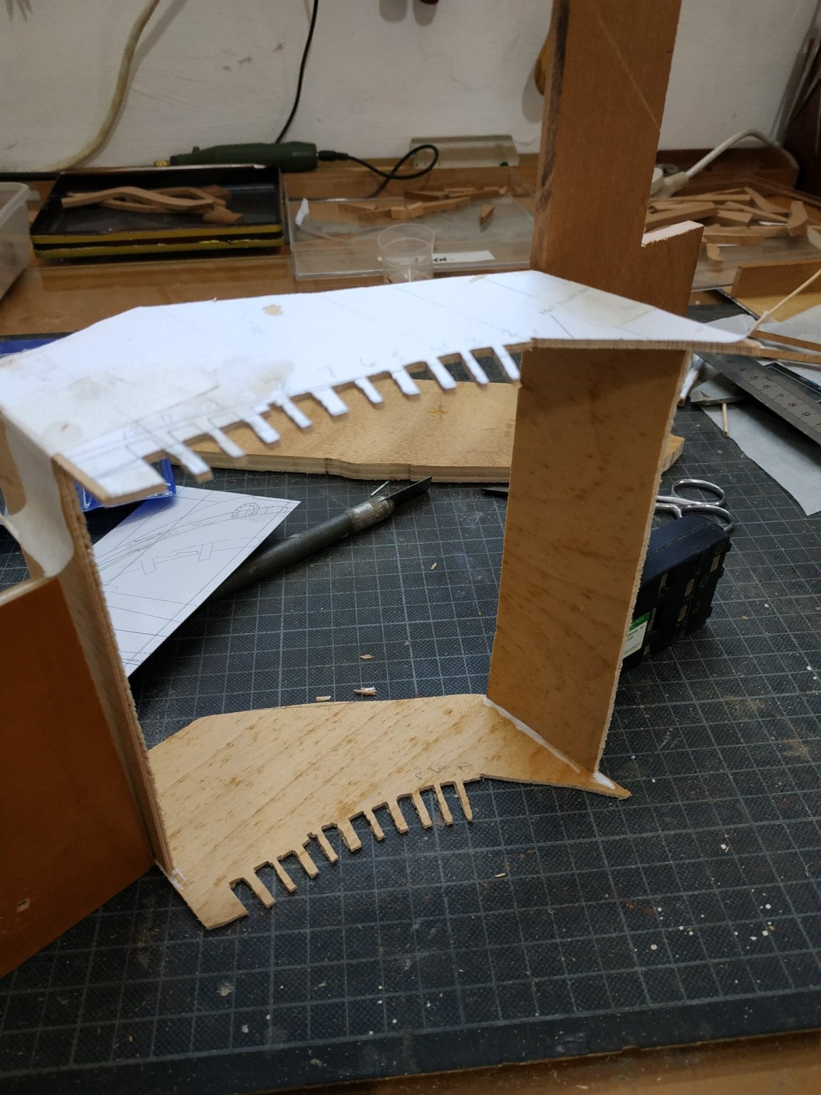
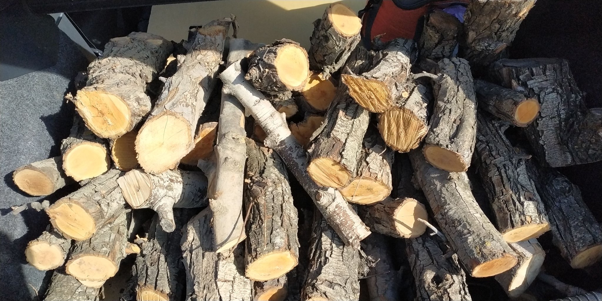
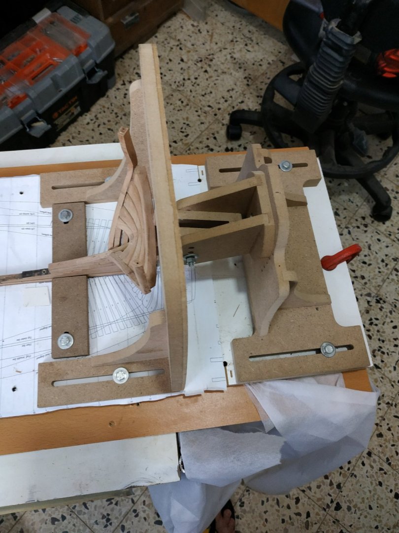
Almost a week without a blog but very eventful.(as you can see by end of saga) Reread opening chapters of B.Frohlich’s “Art of ship modelling” with a bit more understanding. He mentions the change of weather opening gap of 5mm over 100cm model because of change in weather. Well, we had the first rain after 6 months.Its a humid area anyway (coastal) but this cannot explain the accumulated error after fitting the first 6 cants. I hadn’t forgotten the foot bevel. I think the main culprit was an overly tight hawse filling piece.I also think I should have made a couple of the cants better. Unstuck cant and filler pieces ans while waiting to dry,gave thought to alternative ways of aligning and holding the cant pieces while glue dries. I’ve used building jigs but here, the alignment is by the timberline which is sloping.So I took heights from plans for the sides, cut both floor and “roof” together so as to set on board plans, and will be able to turn over and use for other side. Held in place by weight,removable for visualization and access. Shaved down filler piece, remade some cants and cleaned up others and started to place them. Seems better and jig works A friend sourced a supply of PEAR trees that a fruit farmer was selling as kindling!! So with a patient and long-suffering wife for company, drove to the north of the country -couple of hours each way. The trees had been cut to logs and branches last year, to lengths suitable for wood stoves i.e. about 40cms. The thicker logs were mainly split from drying out. Selected half a boot load (it was free) and drove home.(Had said to wife maybe see some local sites or have a meal out, but still semi lockdown precluded this). Drove home and while my wife was making supper, thought I’d see if and how much of the wood was usable. Prepared a couple of pieces with my 10in table saw and with last pass, lost concentration for a second and felt a bag to my thumb. HIT by the saw teeth. A bloody mess, that I couldn’t treat by myself with superglue. Off to local casualty(emergency room) some stitches where possible and bandaging.Declined overnight stay. Will be ok but feeling terribly stupid. Every instruction, Utube etc emphasises safety. I did for most part use sticks, But familiarity and tiredness caused that stupid lapse. I said, in my first blog, that you could learn from my mistakes- this accident is the most important of lessons. PLEASE BE SAFE


- 475 replies
-
- 12
-
-
I have received several books. True, the order is not confirmed and emails are answered after delay, but the product is worth waiting for. Patience.
-
Swan-Class Sloop by Stuglo - FINISHED - 1:48
stuglo replied to stuglo's topic in - Build logs for subjects built 1751 - 1800
I did indeed forget about not using the cutting board The "chisel" are in fact disposable chisel-shaped scalpel type blades. Wickedly sharp but blunt quickly. My problem is my learning curve is in equilibrium with my forgetfulness -
Swan-Class Sloop by Stuglo - FINISHED - 1:48
stuglo replied to stuglo's topic in - Build logs for subjects built 1751 - 1800
# 3 fore cant Relatively simple with 30drg. Bevel, shade area to be removed-phone call- come back and remove the wrong bit!@#$%^ Relatively simple chock (joke) While busy fitting the fore cant (various squares-made both a shorter and taller ones-the latter weighted with a epoxyed battery), the aft cant snagged my elbow (damn attention seeker) Glued it back and because not first time, protected it with the building slip vertical board. #4 fore cant- again change of bevel angle. (27) As previously noted, some beveling of the foot, so it can fit on step. #5 ditto except angle now 22.5deg #6 ditto, angle now 19 deg Suggested by TFFM to make temporary wedges, but want something even more temporary, while check, recheck and recheck all alignments and relation. So after horizontal bracing (glued) used folded card to separate at timberline level and NOTtight rubber band.


- 475 replies
-
- 10
-
-
Swan-Class Sloop by Stuglo - FINISHED - 1:48
stuglo replied to stuglo's topic in - Build logs for subjects built 1751 - 1800
Fore Cant Frame #2 Need to review how to make cants -back to instructions for aft cant in TFFM. All cants are 4.77mm wide. Remember that the other “direction” will be the inner and outer hull surface, so extra will be removed later with hull sanding. Decided to try again with the chocks- in any case shorter blanks are far less wasteful. With#2 the bevel of the chuck is minimal. So I cheated. Made it as one piece, chiseled the chock out, and reassembled it. Looks o.k. Triple check bevel angles, each is different. #2 is 32.5degs TFFM also mentions additional small bevel at foot because the angled foot is wider than - I tried this before gluing, but insufficient, so remove some from base #1 can with a chisel It's easier after gluing so with do this with the rest of ribs as required. Trunnels(staggered pattern as suggested). Hold in piece vice for position and “verticality”and use drill press. Trunnels oversize at 0.7mm, but I want to see them. (also difficult for me to make smaller) Fit, check “foot” doesn’t overstep step.If necessary pare back by beveling neighbouring #1cant foot (very slightly). Glue,hold in place until holds up by itself, and adjust the angle so vertical (square) and alignment with the timberline as on the breadth plan ( previously made height card and holder). Keep rechecking position maintained while glue dries( present weather, 5-7 mins) Repeat for port twin. They look symmetrical, so probably OK.

-
Not really welcome back because as I consult your videos frequently, you have been continuously here. Your a bit ahead of me in your build (at least a year) so don't disappear. I would endorse whole heartedly the 3D renderings. Those of us ignorant in naval architecture need such a visual aid. It goes without saying, your work is superb
-
Swan-Class Sloop by Stuglo - FINISHED - 1:48
stuglo replied to stuglo's topic in - Build logs for subjects built 1751 - 1800
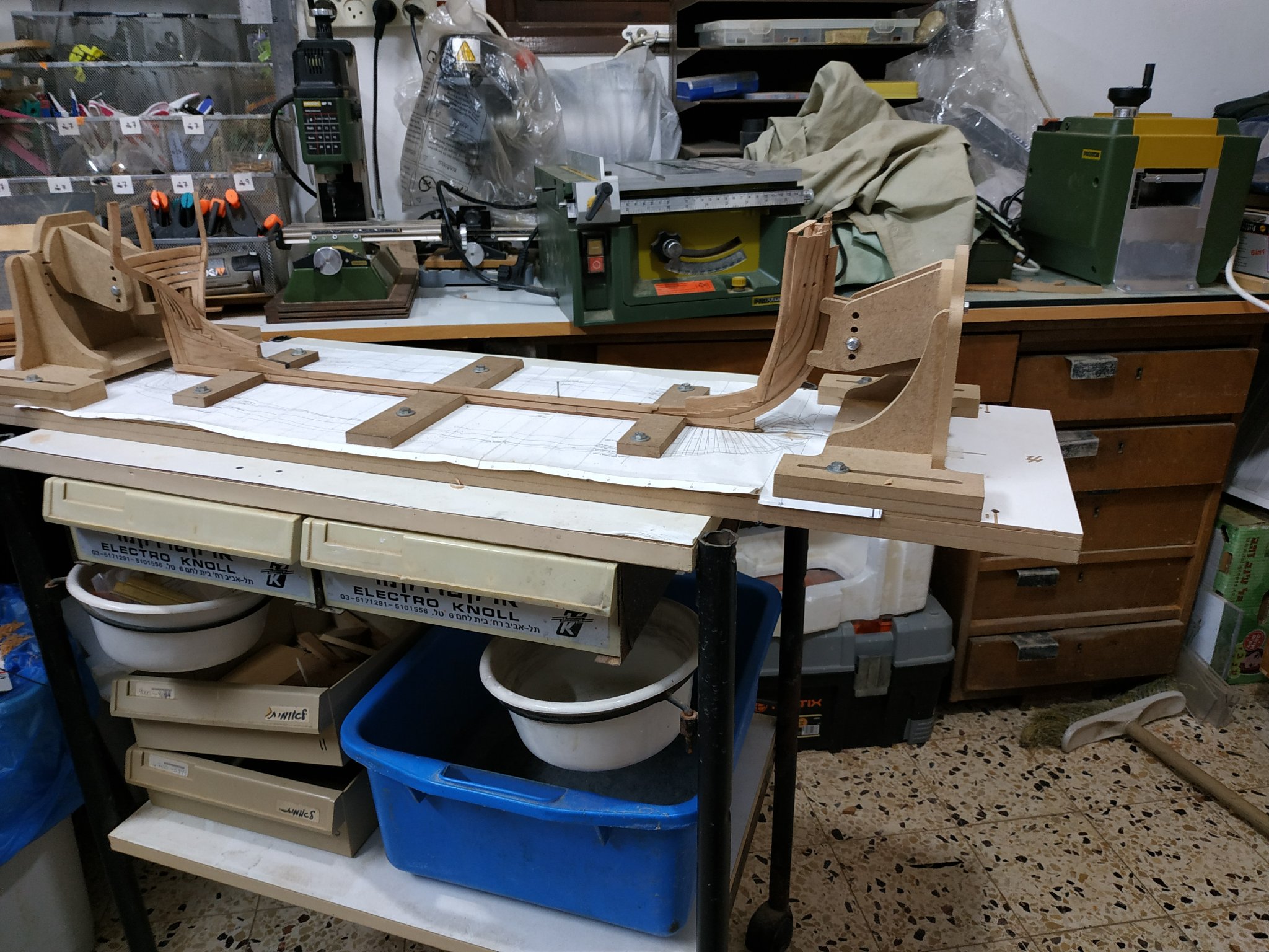
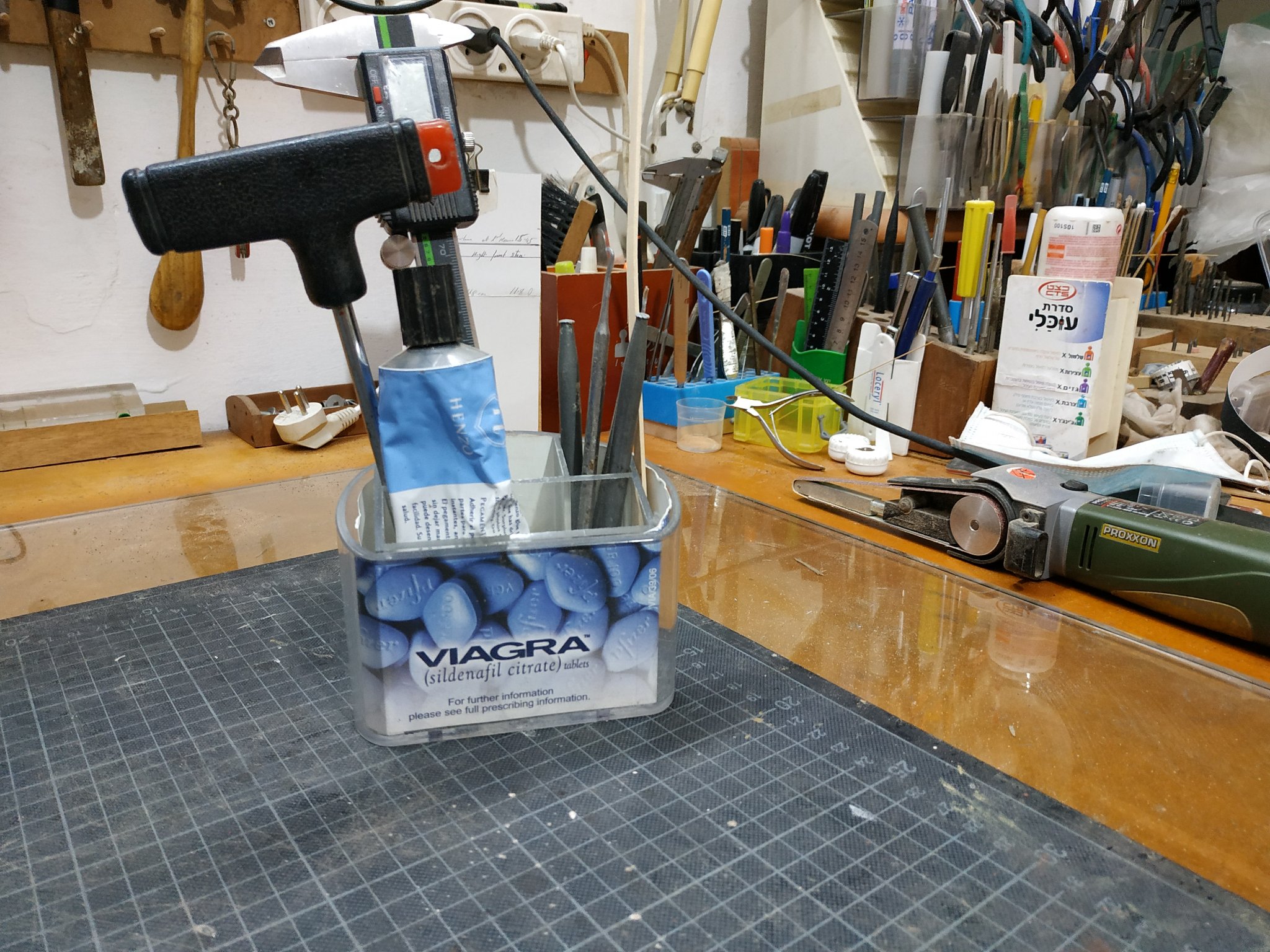
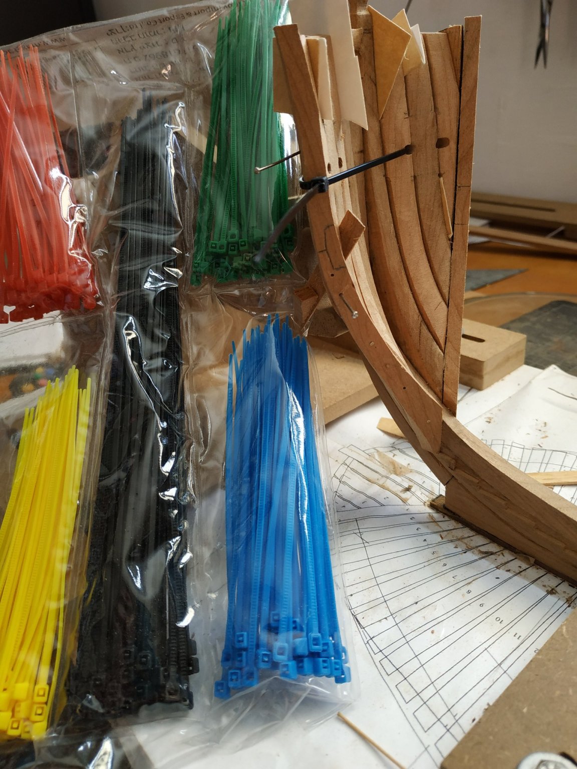
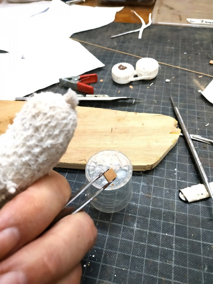
The filling pieces. Some specific measurements are given to make an oversize plug to fill the gap between the #4 hawse piece and the 1st cant. It should be dagger shaped with a cross section triangular shape. Couldn’t really see from the diagram how to do this, so took a spoiled hawse piece and shaped one side (length) to the 34.5 bevel so as to match the cant. The importance is to match the “back”. Then trial and error with the hand-held band sander, shaped until fit. The much larger than necessary piece of wood allowed for lots of trial and error. Anyway, it seems to work for me. When fitted and dried, the fore shaping can be fought out. The whole structure isn’t particularly rigid, so have left finishing inside and out until later in the build. The 1st cant remains in its appropriate position. Note small ties-bought packet for $1.50-they are very useful. Trying out puting model on moveable table for easier access/rotation, and leaving my work space as free as possible. Repurpose stationery holder to help tools stay upright (euphemism)


-
Swan-Class Sloop by Stuglo - FINISHED - 1:48
stuglo replied to stuglo's topic in - Build logs for subjects built 1751 - 1800
Continuing to work on hawse #4 last week, the port side seemed fair but left a peculiar space for the filler. The starboard wouldn’t fit at all. Rechecked the 1st cant against the breadth plan and found that somehow the angle and therefore the distance between timberheads had narrowed considerably. I think this may have been due to the use of spring clamps that exerted too much pressure.I unglued and separated all the hawse pieces and cants. (A BLUNT blade is better for this.) Having separated the cant several times they look a bit worse for ware- so remade them. The hawse pieces needed cleaning up and fortunately able to separate and reuse both bollard timbers and their bridging chock. Used my jig to hang the relevant part of the body and align the timberline of the cants while using set squares to check against the breadth plan. As Richard Feliciano mentions, the relation to the step is secondary. Remade starboard hawse#2 as old was damaged when removed. Wore out 3 small files (and hurting shoulders) making grooves so thought there must be a way to machine these. ** Angle marked as before, held vertically in vice with so direction becomes 90deg, using 3mm milling bit much like a drill press, but incrementally moved until depth required. Quicker and cleaner groove. Hawse#3 both OK At last back to hawse #4 (taken me 4 days to get here). Blanks of 7.16mm Even with the tramlines as advised (to ensure vertical angle of short bevel) not easy.The starboard worked first time, but the port was more difficult as use same side as disk sander but at opposite angle. Took 3 attempts. After that it's the same principle bevels, but leaving the weird shape. Who cares-it fits!! Tomorrow the filler pieces.


-
Swan-Class Sloop by Stuglo - FINISHED - 1:48
stuglo replied to stuglo's topic in - Build logs for subjects built 1751 - 1800
Thank you. As you will see when I post next blog, I have remade #1 cants and hawses. I worked off the breadth and body plans with vertical jig and several set squares, and yes, the step is out despite using a cut out of the sheer plans. Be very happy to share problems and solutions. As advised, precision all important,but so much is interdependent that its difficult to know the fundamental point of reference. (PS the etched parts are great) -
Old Floquil paints?
stuglo replied to MEDDO's topic in Painting, finishing and weathering products and techniques
I have the "little red book" -
Old Floquil paints?
stuglo replied to MEDDO's topic in Painting, finishing and weathering products and techniques
Last year I used some unopened bottles at least 15 years old. I added a little thinners and it was fantastic. I know nothing on the market to compare. I store all paints upside down anyway. I brushed and the result was very satisfactory. -
I have just received my kit of Le Coureur. After purchasing more than 20 kits over 30 years, this sets a new and very high standard. The packaging, detail, ingenuity and value for money makes this a priority on anyone's list.
-
Swan-Class Sloop by Stuglo - FINISHED - 1:48
stuglo replied to stuglo's topic in - Build logs for subjects built 1751 - 1800


-
Swan-Class Sloop by Stuglo - FINISHED - 1:48
stuglo replied to stuglo's topic in - Build logs for subjects built 1751 - 1800
Checked accumulated max. width of 2xhawses #1and#2, 34.76mm instead of 34.98 -I can live with that. Hawse piece #3 As same bevel as before, at the foot, and outer surface from fore edge. Align this edge with the aft edge of#2, spot rubber glue T foot and where grooves will be.Remember the 0.4 spacers. While stable, holes for guide pins again avoiding air spaces. Mark aft edge of #2 on inner surface#3. I will bevel this later so the piece will be more stable.Mark grooves fore and aft. corresponding to their neighbour on #2. . This time they match the pattern. Similarly mark levels of air spaces. The groove is only 1/3 of depth as its neighbour-1mm Again clamp on plan with extended lines of hawse holes, to table. The same 3mm file- and I get to use my new depth gauge. A similar groove is made on other side and parallel. Recheck airspace marks, and mill to within a couple of mm, taking off a depth 0.4 . Remember to use this depth shim to support piece. Extend the airspaces to marks and finish with 45deg incision as before. Glue to neighbouring #2 either side of groove, and at foot to cant. Ensure spacing with 0.8 spacers. About to glue second pieced and-WAIT. Something's not OK The piece has lost weight- its too THIN. Check- only 4.68mm not 7.69mm (!@#$%^&*-expletive) ?How . Must have picked up the wrong blank when resumed work . Perhaps more used to the size of cants than hawses. ? Senior moment. My wife says I did stupid things even when a youngster-I can't remember. Anyway- good lesson- if it appears to be going well-see where you are going wrong!!!! Start again tomorrow.
-
Has anyone any idea how the figurehead would/could have looked like?
-
Swan-Class Sloop by Stuglo - FINISHED - 1:48
stuglo replied to stuglo's topic in - Build logs for subjects built 1751 - 1800
No good deed goes unpunished. I was helping my wife to diet by removing temptation. -
Swan-Class Sloop by Stuglo - FINISHED - 1:48
stuglo replied to stuglo's topic in - Build logs for subjects built 1751 - 1800
Wasn't 100% happy with situation and was undecided whether to start again and remake the last few pieces. This morning things looked a little better and decided to go ahead , finish the #2 hawse pieces and fit them. When aligning the levels of groove and air spaces, not only check against parts already fitted, but against each other (they should mirror exactly). Assuming the guide pins already prepared (if not temporarily rubber glue in place so as to drill for guiding pins , as otherwise it moves so easily). Also remember to place the spacers (in this case, 0.8 below and 0.4 above) then glue the thickness not milled plus the foot. Locate the pins (not so easy as is usually) and clamp CAREFULLY so as to avoid slippage. I think it obvious, but do one side at a time and only after glue dry, replace pins with trunnels, and then go to other side. Hawse #3A Apparent problem- book says blank of 14.5in (7.69mm) but detail on plan says 14in. There is a diagram of the overall width at this stage in the book 95in. deduct the #3 and left with 29in-for pair. Thus 14.5un is correct. I then notice piece #4 is 13.5in in book but 14in on plan- so in the end will have same result. Nevertheless, I'll go with the book (15,14.5,14,sounds better than 15,14,14,) Note, the bevel is still 34.5. **PS** Don't eat chocolate cake with fingers when handling wood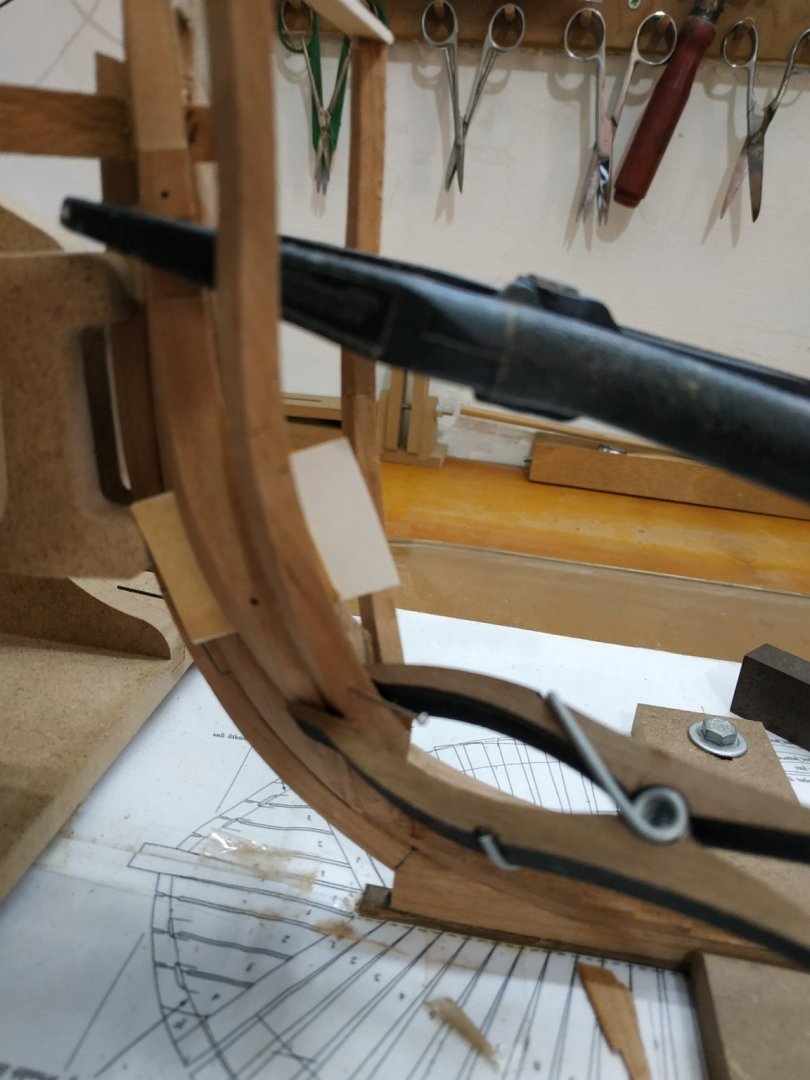
-
Swan-Class Sloop by Stuglo - FINISHED - 1:48
stuglo replied to stuglo's topic in - Build logs for subjects built 1751 - 1800
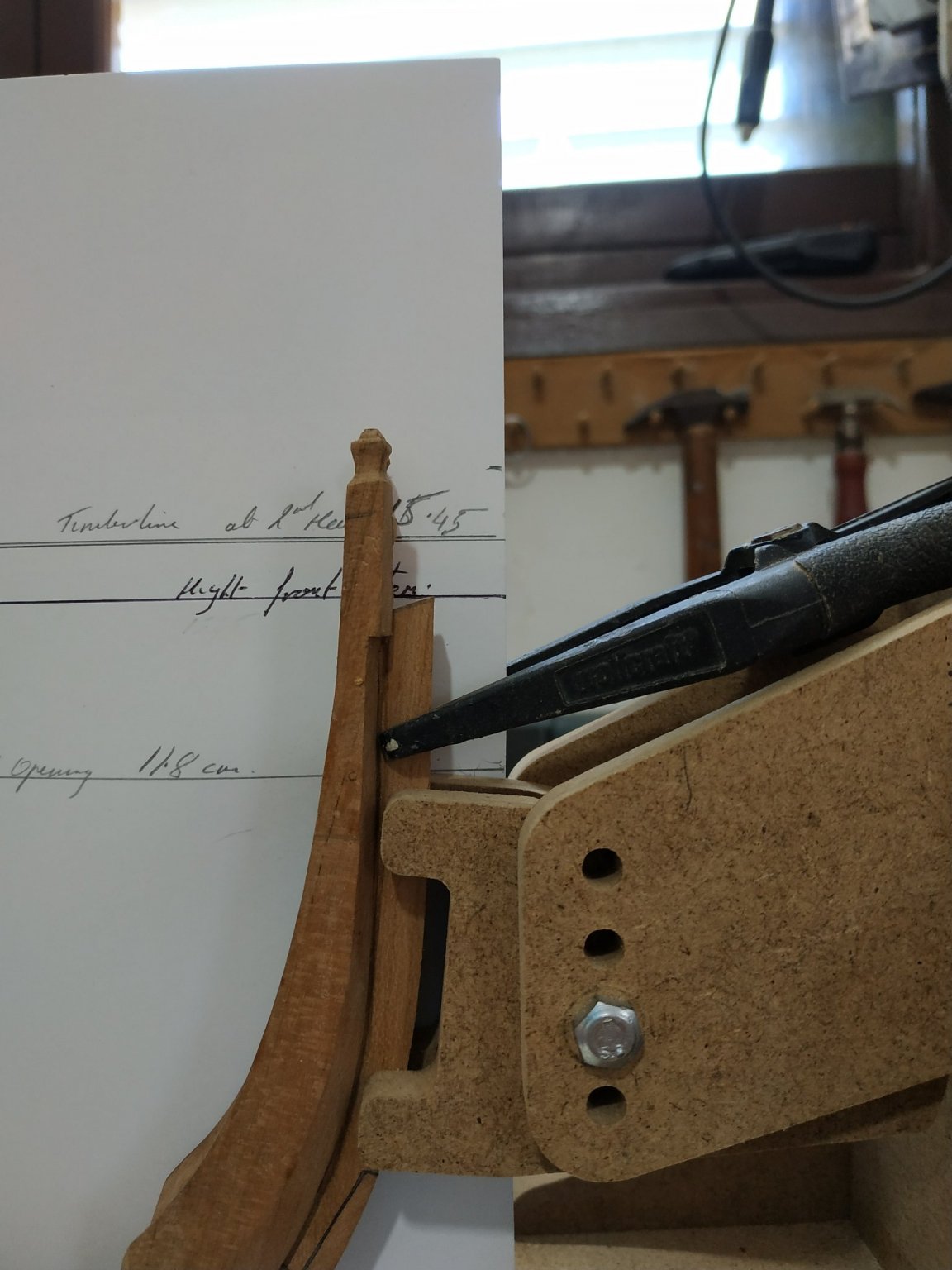
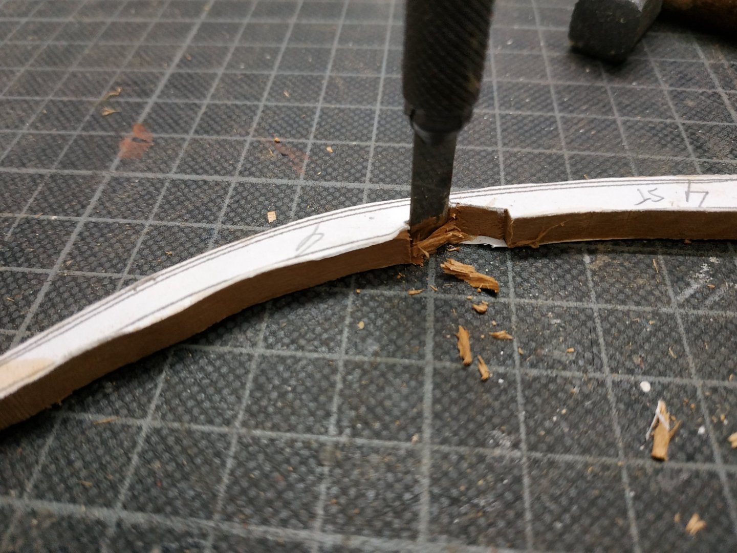
15th and 16th Oct. (originally tried to post on friday, but after writing it all out, deleted instead of submit - "you pressed the wrong button,bacon brain"-Miss Piggy) Anyway, with timberheads removed, reduced the height of stem/bowsprit grove to its high point of 14.5mm (using the sliding sander) Reposition timberheads with reference to aft aspect of rabbet and lower foot . Luckily (rabbet's foot-ha!ha!) reworking to follow curve is easy. The bowsprit aperture remains the same. Although the bridging chock remained in place, each side needs to be aligned separately. New pin guides are needed. Result is my timberline is 2mm higher than the plan- ? good enough. Refit 1st cant -had to reread TFFM as forgotten already although it was only a few days ago. I had to add a slim shim to "sole" of timberhead . This wood has quite a marked grain pattern so as long as additions are in parallel, they blend very well. In any case, most will be hidden. Probably just me and my conscience know and care. As others have remarked, surprisingly small changes/variations can have significant effects. On the other hand, wood can be very forgiving and adaptable - don't be frightened dismantling and making corrections. At last, returning to #2 hawse piece: The lower part of the opening is at 11.8mm -just 1mm below the markings on my cut out plan. Go with TFFM and use the master plan reference. As advised, place the upper locator pin below the are which will become the air space (about 4.24mm above hawse hole). Good and detailed advice about how to file the groove. No so simple as I have a tendency to "rock" and the groove dips ao one or both ends). Extend lines on copy fore area, place piece lining up the rabbet and clamp both to table. Given the thickness of the piece and wanting to form groove of depth 3.18mm, blocks of thickness 5.25 were taped on either side. This groove is 2/3 of total (its neighbour #3 is 1/3). My file is 3.17 diam.-the depth of the groove. So when to top is flush with the piece, I've done the job. The clamping to the table and the direction (slope) outlined on the plan, make this much easier. My next problem is how to widen the the diameter of the groove to 3.98mm but I do not have a 4mm file. I'll proceed and think of a solution later (or some kind reader can tell me). The piece has upper and lower air spaces on inner and outer faces- the lower at same height as its partner on the timberhead (and extending to end of piece) the upper starting 18mm above it. The required 0.4mm is removed by milling -ensuring the parts are supported by a 0.4 shim when milling the second side.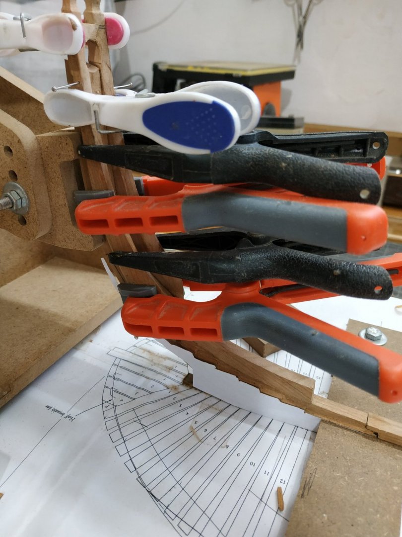


-
Swan-Class Sloop by Stuglo - FINISHED - 1:48
stuglo replied to stuglo's topic in - Build logs for subjects built 1751 - 1800
This is good advice illustrated by superb work, as good as the 3D computer illustration. I have of course left meat on the wrong bits,and not on others. I plan to finish each stage then, when see the fuller picture, decide where to remake . Please continue to commit-this is how we learn. -
Swan-Class Sloop by Stuglo - FINISHED - 1:48
stuglo replied to stuglo's topic in - Build logs for subjects built 1751 - 1800
later that night...... So as not to leave my friends in suspense, will give an update. Decided to try and remove (again) the 1st cant and the timberheads with bridging block as a whole. Success. Marvelous how alcohol helps a problem. The steps are the main problem and using a cutout against the keel, reconfigure with new chisel blade. 2+mm removed . The slightly thicker lower stem is corrected for at the same time as it contributes to the height of the steps. Lessons to be learned: (mostly obvious therefore relearned) At every stage, check,measure,check remeasure again. Check against whole plan not just part. If something is wrong find out why and fix it. I initially thought to leave the problem and compensate with a later -this is laziness and a recipe for disaster. At the least, dissatisfaction or at worst (God forbid) abandoning the project . There are plenty good people out there only too willing help-listen to their advice. Now we can all rest easy Goodnight