stuglo
-
Posts
707 -
Joined
-
Last visited
Content Type
Profiles
Forums
Gallery
Events
Everything posted by stuglo
-
Swan-Class Sloop by Stuglo - FINISHED - 1:48
stuglo replied to stuglo's topic in - Build logs for subjects built 1751 - 1800
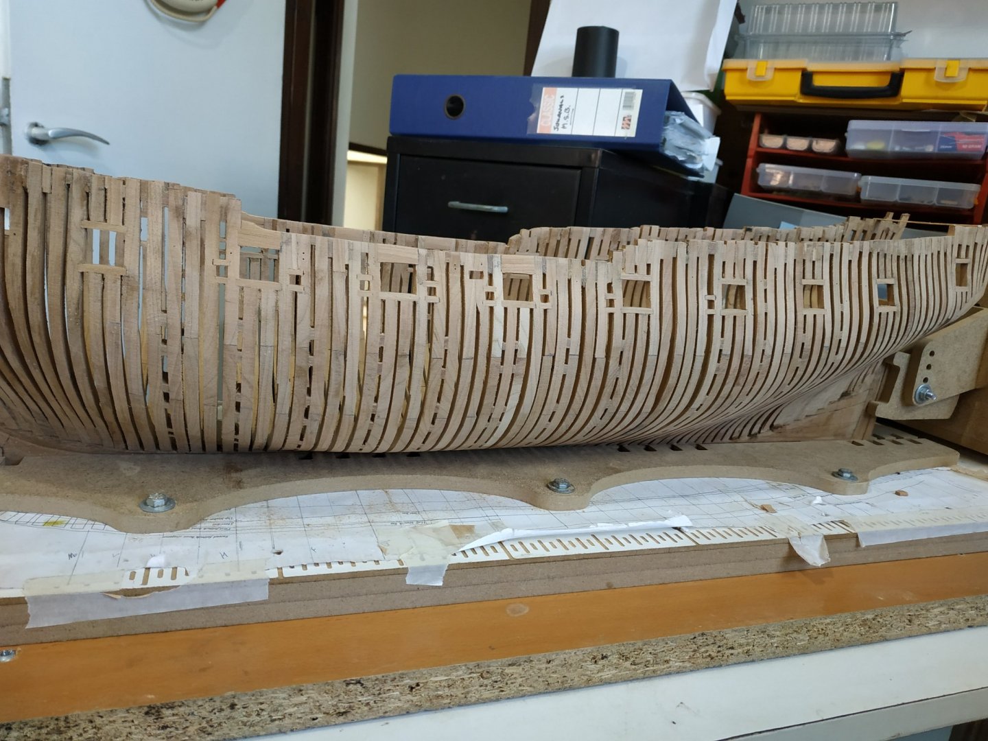
Strakes #12 and #13 #13 - 2.12mmX6.9mm, abutting #14. From #Kaft to notch, narrows to 2.65mm Aft narrows to 4.5mm. MISTAKE is now glaring. After much mental indigestion, resolve to UNdo and REdo. Crowding aft will not allow ceiling planks without excessive narrowing to points.More importantly, the choice for the run of the desk clamp was wrong.This time, using the upper desk clamp as source, made the aft (unmarked on plan)section, parallel to this. The upper edge of #15 now to run to upper edge of #4 transom. The gap between #8 and #13 is still too narrow, (probably because of insufficient narrowing of #6 and #7)but will use stealers/dropped planks rather than remake these.


-
Swan-Class Sloop by Stuglo - FINISHED - 1:48
stuglo replied to stuglo's topic in - Build logs for subjects built 1751 - 1800
Strakes #12-15 The upper pair form the lower deck clamp. therefore these will be fitted before #12and #13 To establish the height/run reference to the sheer plan, BUT the line only is shown extending to station #16 and only later when trial fitting , do I think that it should extend to aft cant at base #4 Transom. The deck will sit on beams are 3.18,that are "let down"-countersunk, by .53mm, therefore 2.65mm below line. Rather than mark this directly I put a temporary full length strake of this width to help give a smooth curve which has been difficult, and fix the strake #15 abutting to this. The plan calls for TOP and BUTT joints. I've never done this before. Copying the plan to scale 1:48 and using cut-outs , the shape and curve is obtained. The #15 is nominally 2.12 thick and 6.89 wide, but with the curve, obviously wider blank is used. This is thinned from above to below, so that when joined to #14, the lower edge has width of 1.59mm I can think of no easy way to do this other than adjustment by sanding after both strakes are fixed. Also the upper edge of #15 is "camfered" to a horizontal edge. There appears to be a problem with fitting the aft ends of the strakes, as the lower strakes are not adequately tapered. I narrowed #8 but still a problem that await a solution to avoid tapering to a point.


-
Swan-Class Sloop by Stuglo - FINISHED - 1:48
stuglo replied to stuglo's topic in - Build logs for subjects built 1751 - 1800
Your correct. I had a mental block thinking this not related to external planking that I have done many times. Nevertheless, bending sideways is difficult, especially without a jig. I am using the planking expansion plan to fashion the deck clamps and the first few seem to be working out. I'll keep you posted -
Swan-Class Sloop by Stuglo - FINISHED - 1:48
stuglo replied to stuglo's topic in - Build logs for subjects built 1751 - 1800
https://modelshipworld.com/forum/17-model-tips-and-tricks-and-making-jigs/ -
Swan-Class Sloop by Stuglo - FINISHED - 1:48
stuglo replied to stuglo's topic in - Build logs for subjects built 1751 - 1800
Depth Gauge (adapted from TFFM and Kevin Kenny) Necessary for accurate placement of deck clamps etc. Materials-simple and to hand. Required to be adaptable to varying width and depth of hull and curves that restrict fixed perpendicular “arm” Therefore, system that moves both up and down, side to side and arc. The axis-screw with nylon washer, wing nut. Clamps, to lock position of sliding bar. Later addition of pointed foot -broken 0.8mm drill bit The whole turned 180 to mark the opposite hull wall. (pictures posted on jig site) -
Swan-Class Sloop by Stuglo - FINISHED - 1:48
stuglo replied to stuglo's topic in - Build logs for subjects built 1751 - 1800
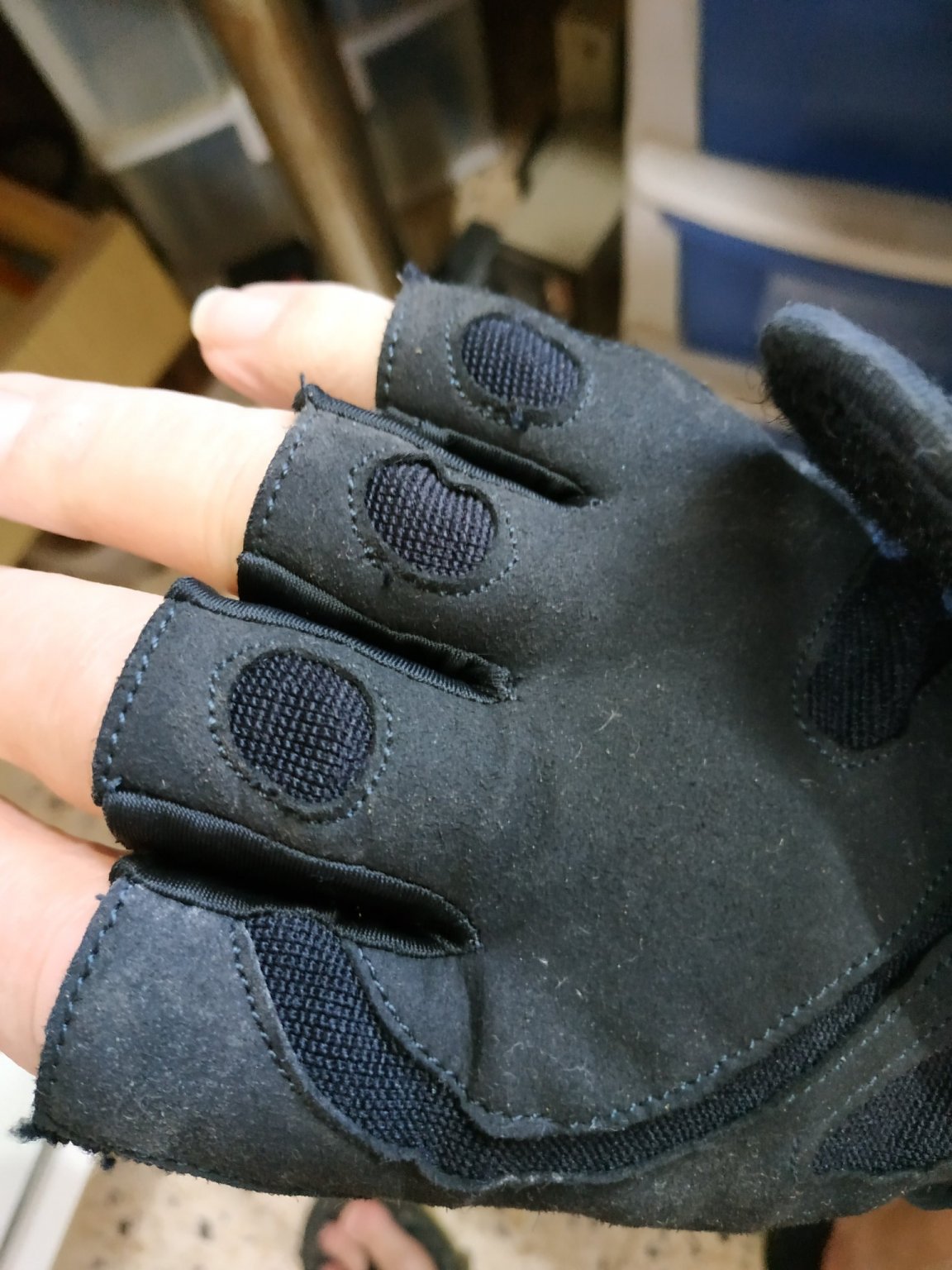
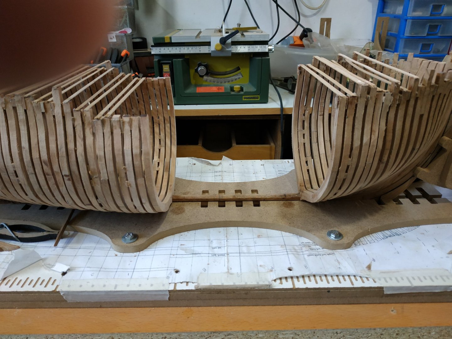
****The problem of thick wood and bending sideways.**** Over relatively short sections, this isn’t easy. Soaking, heat doesn’t always avoid kinking and splitting and the compound curve adds complication. ?Each piece would require its own jig or better still cut the piece as a curve - a sort of spilling. I am trying POPLAR as it is relatively soft. One way is to let a wetted plank dry in situ while being held in place various clamps.( Because of the position and narrow gaps between frames, these will have to be made and sourcing the hardware will be difficult and course delays.) When dry, it can be glued and re-clamped. I’m trying something else. The piece, with PVA glue, is nailed in position on each frame with some side clamping. Working quickly with drill and forceps from one end, it is forced to the required curve.The argument against is that it sets up large forces in the wood and the sharpness of the curve is a limiting factor. However, I applied its opposite number straight away, and, after leaving the glue to set for a couple of hours, with the pins in place,judiciously wet the wood (but not soaked as usually done before shaping)and left overnight to dry. The result is fair, needs some remedial work, but is a possible solution for someone lazy/impatient like myself. I invite comments. When removing the pins, kept skinning my knuckles on the sharp timbertops, thus the protection of gym glove!!

-
Swan-Class Sloop by Stuglo - FINISHED - 1:48
stuglo replied to stuglo's topic in - Build logs for subjects built 1751 - 1800
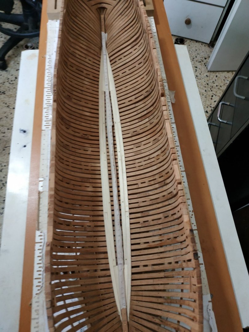
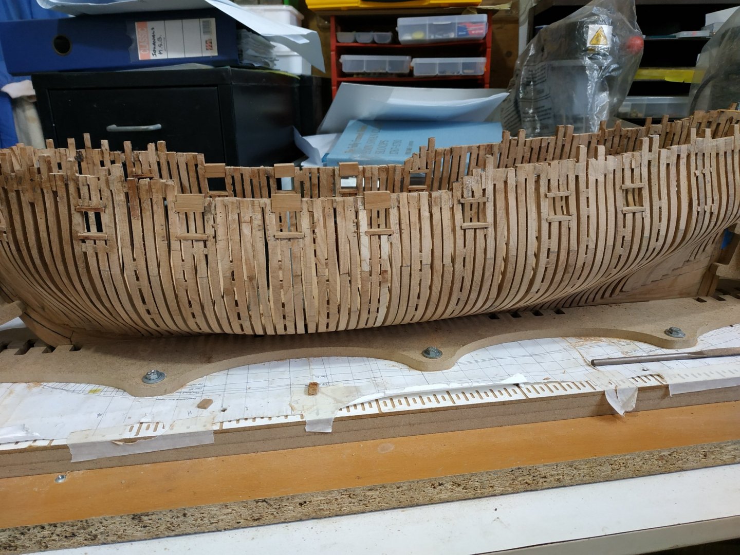
Ceiling planks. A series of 3 thin planks above the limber strakes-optional, and will probably fit later, and only on the port side. “Thickstuff” over the floor heads. Strakes #6,#7,#8. The middle narrows and end in a notch formed by its upper and lower neighbours thus avoiding narrowing to a point. Using the (as usual good) advice of TFFM, used paper strips to mark the line of #6 as measured from the upper margin outer limber strake. Starting with 15.9mm amidships, the spacings are given for to aft. #6 strake is 6.36mm wide and 1.6 mm thick Given the 3 step pattern and the same number of ceiling planks (not yet fitted), this #6 butts on same frame as outer limber (#2). Tapering aft to 5.57, a butt on cant 11, it continues to the keelson. Forewards, it narrows to 4mm. An angled notch is cut at level #5cant, ane the stake is further narrowed before this so that the “waist” of the notch is 2.65mm. The whole is camfered on lower edge. #7, middle strake, is 7.42 wide and 2.39thick before narrowing for lower edge to fit the notch on #6, and 5.3mm aft to finish aft cantand keelson. Both edges camfered. #8 strake width 6.36 and thickness 1.69mm. Notched and narrowed to compliment #6 and enclose the end of #7. The aft end rises above the level of the keelson to the aft cant despite some narrowing. TFFM mentions this shouldn’t be (if I understand correctly) Kenny narrows it further to fit but Dan Vardas seems to leave it -so will I at present.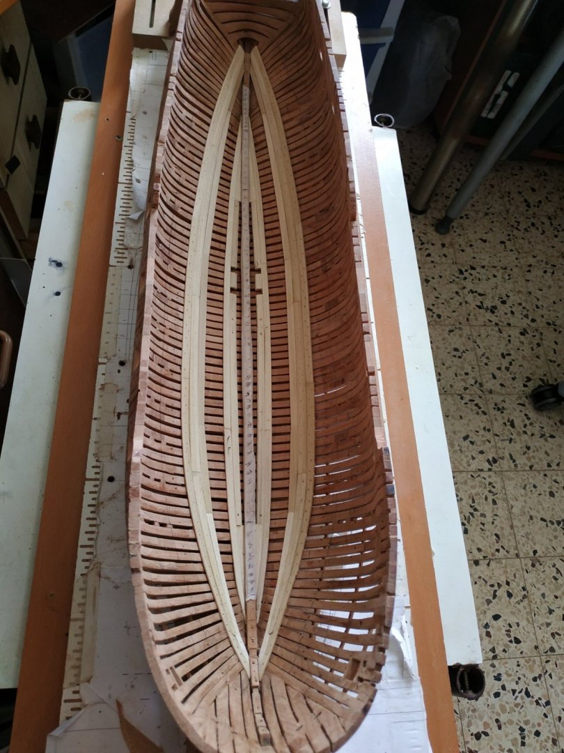
-
Swan-Class Sloop by Stuglo - FINISHED - 1:48
stuglo replied to stuglo's topic in - Build logs for subjects built 1751 - 1800
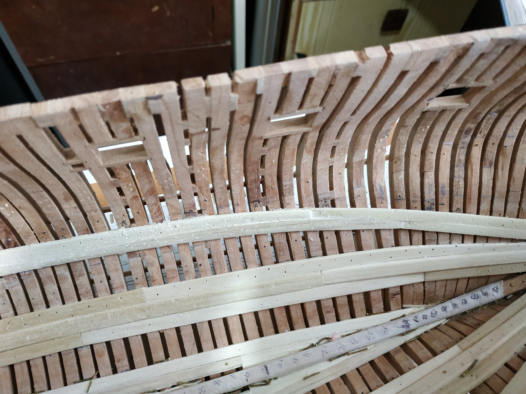
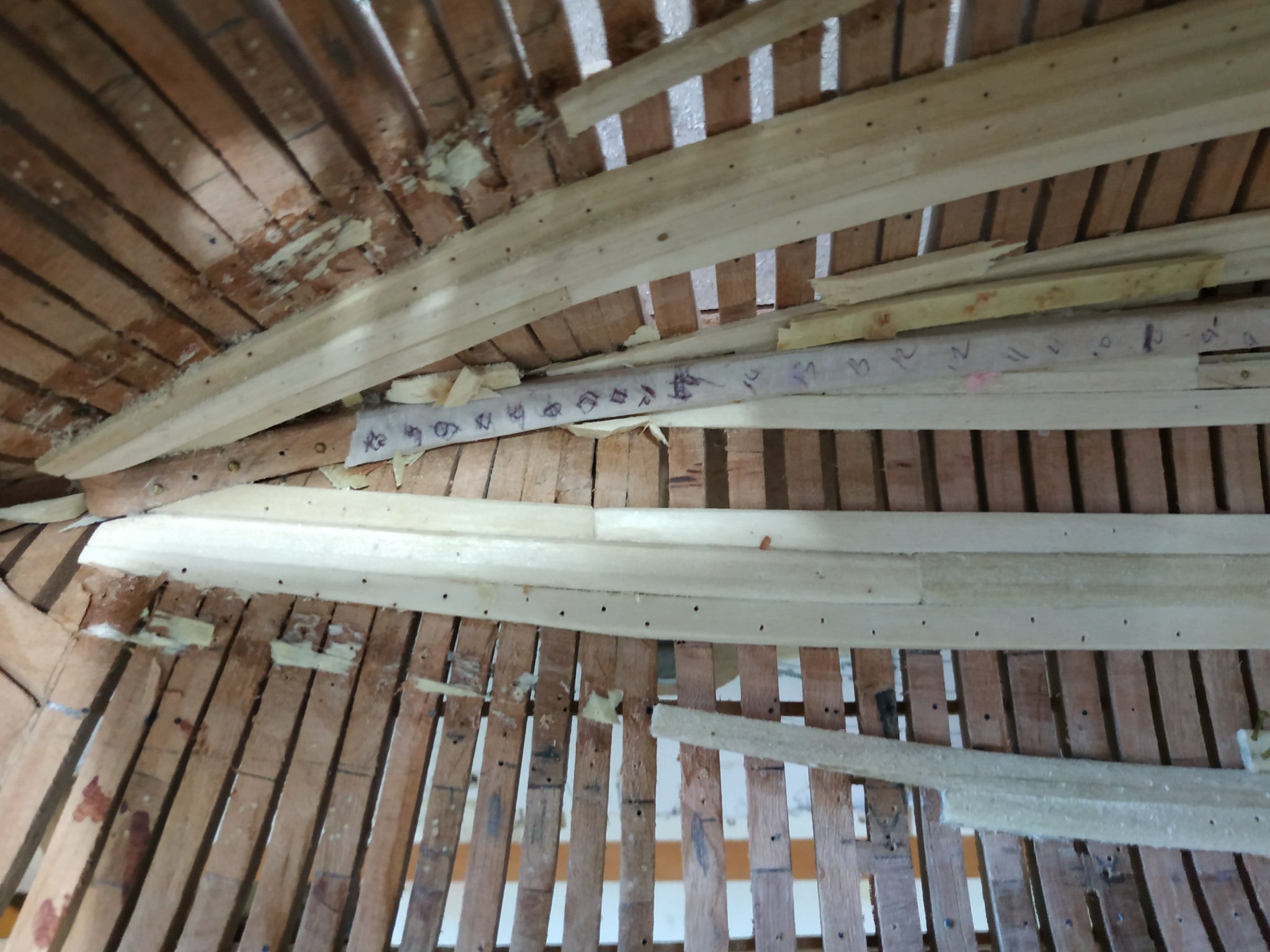
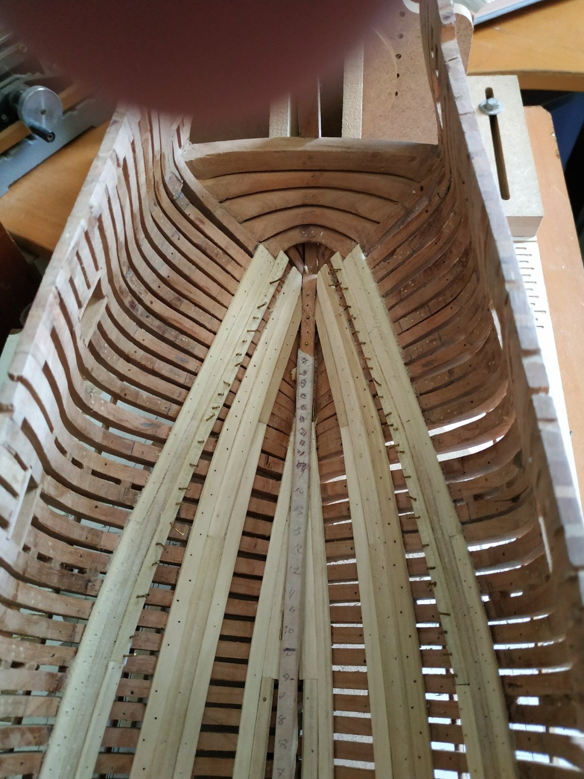
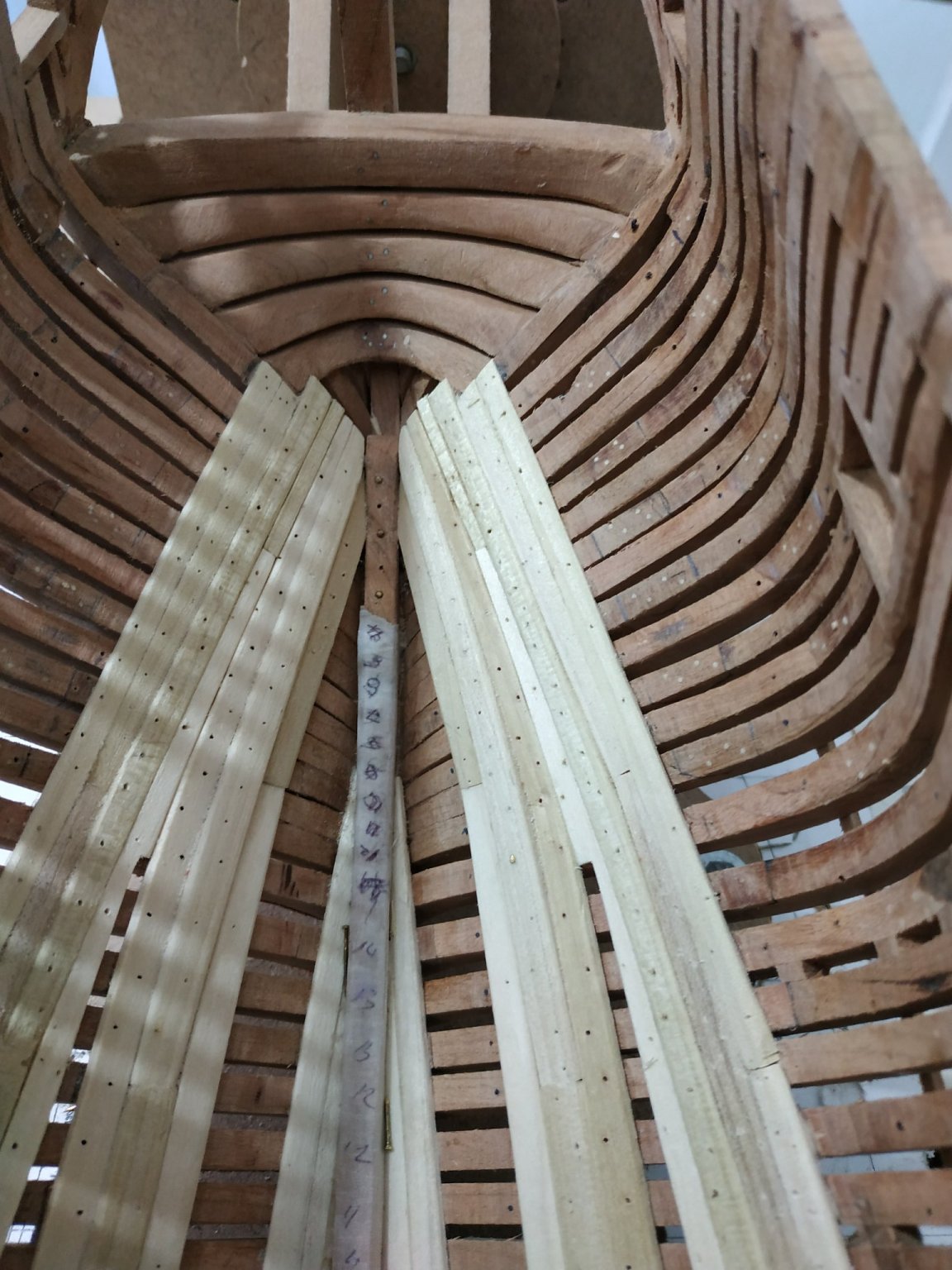
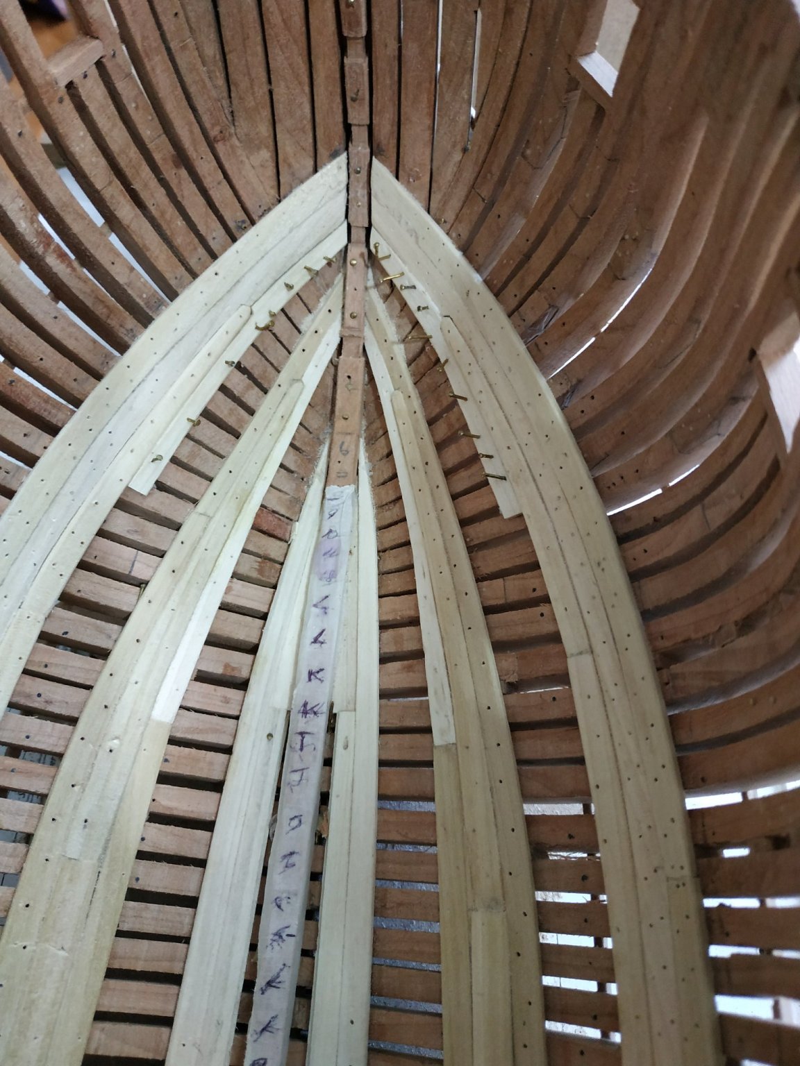
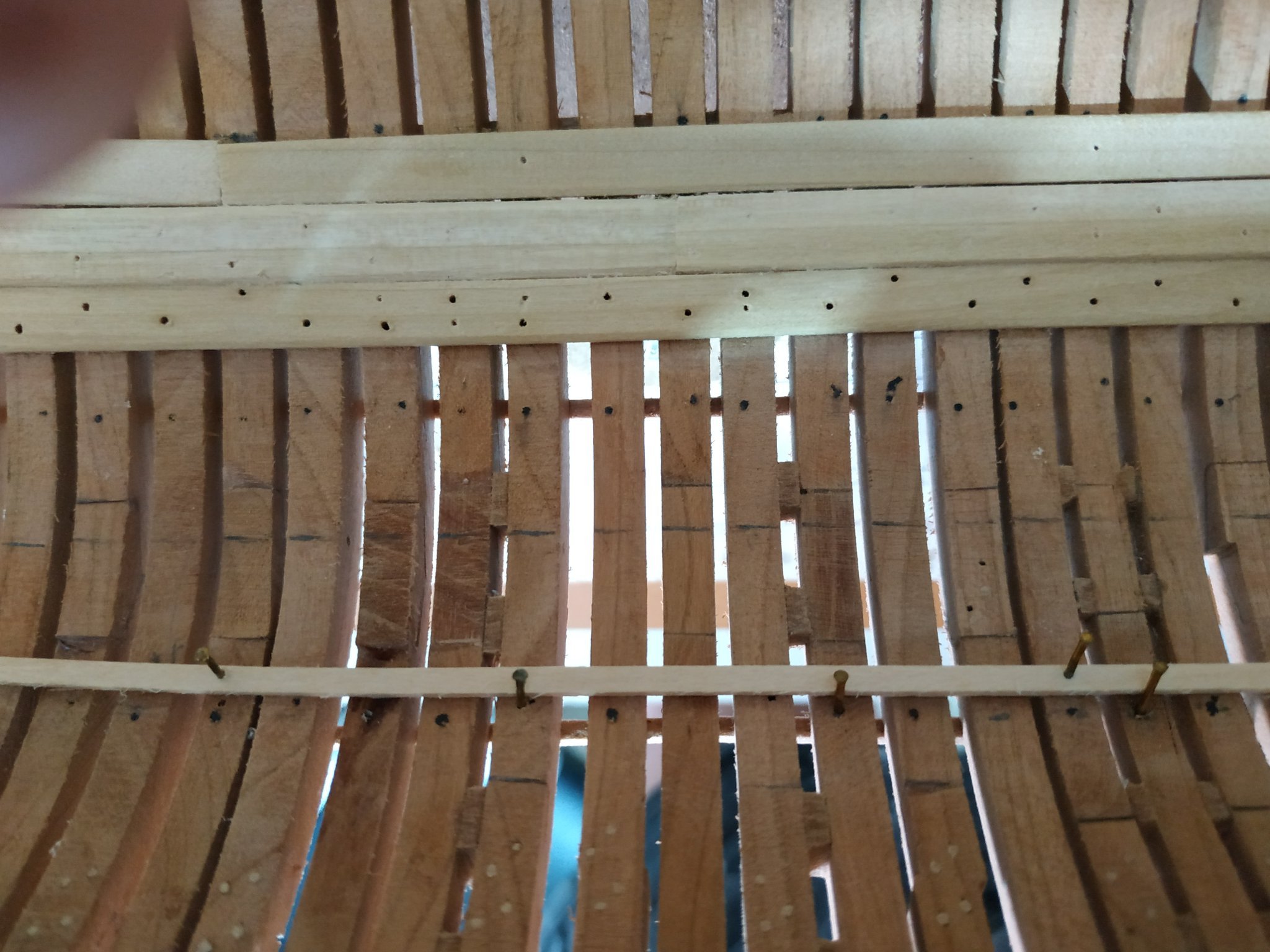
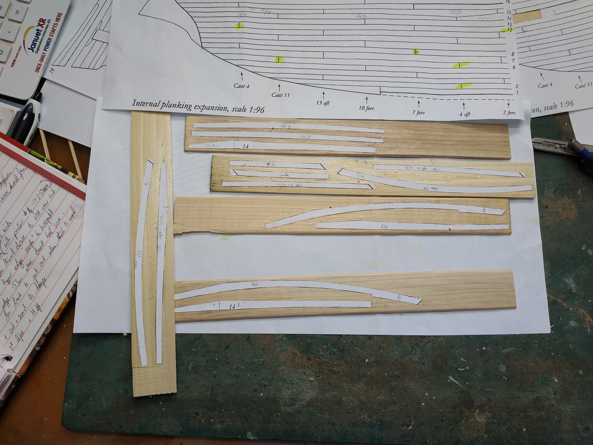
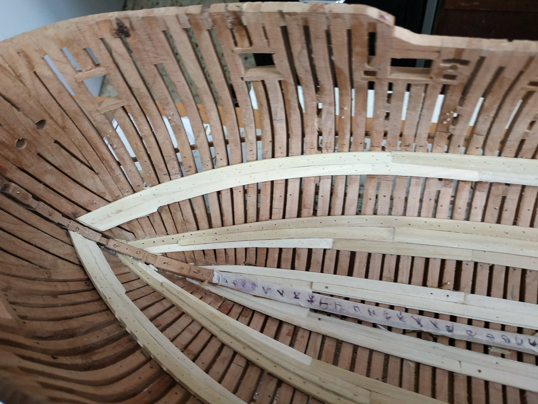
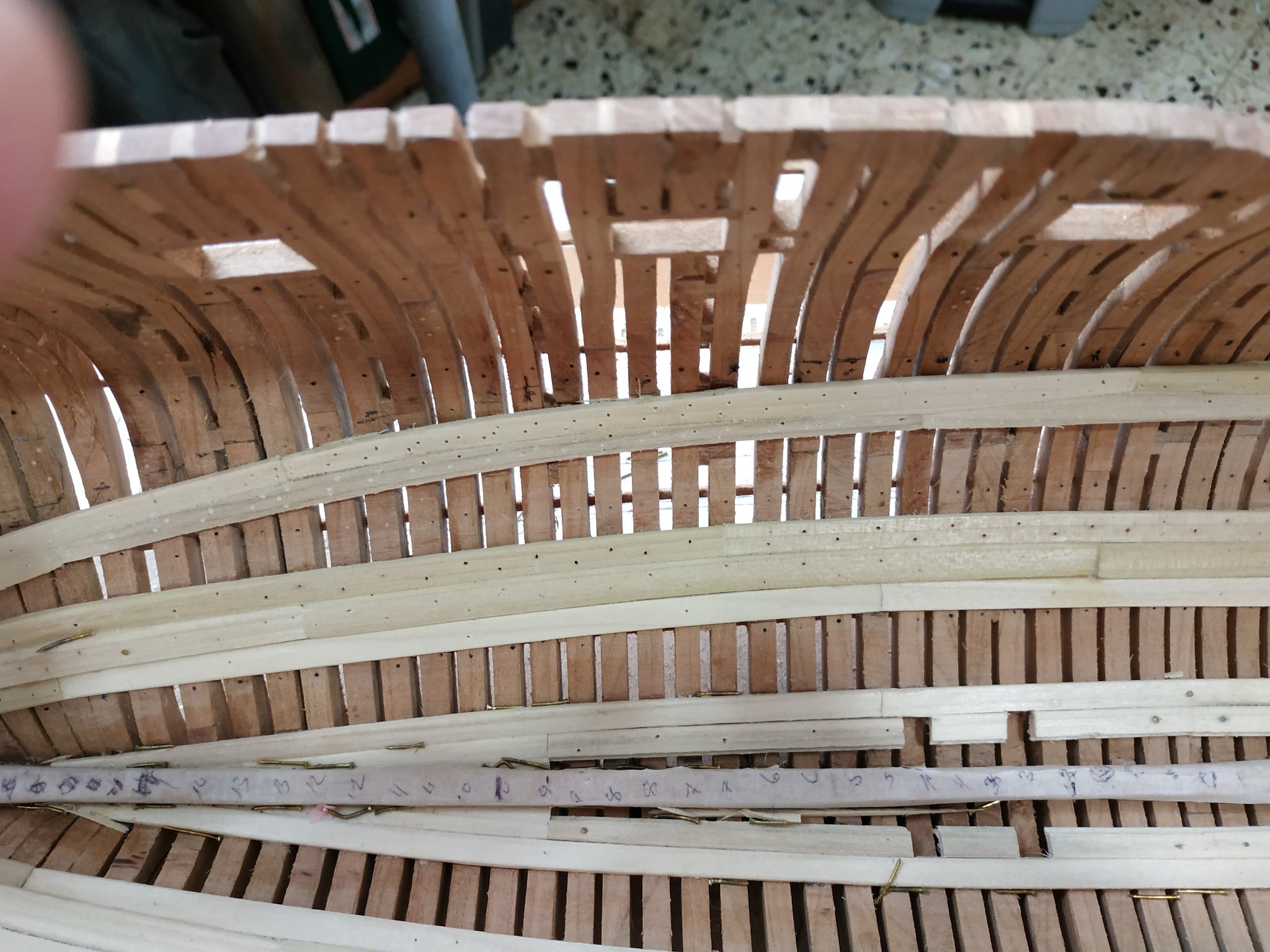
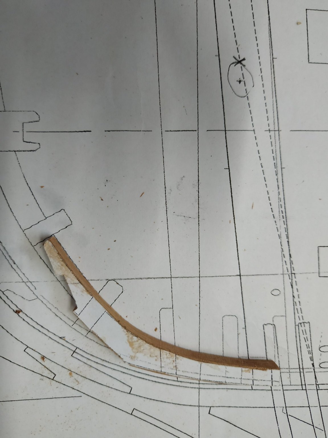
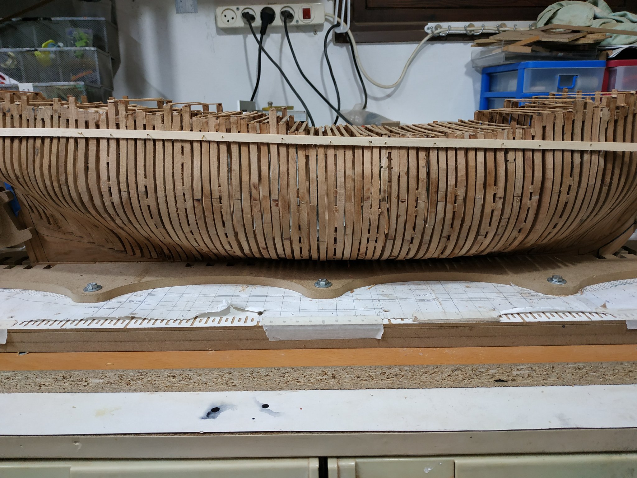
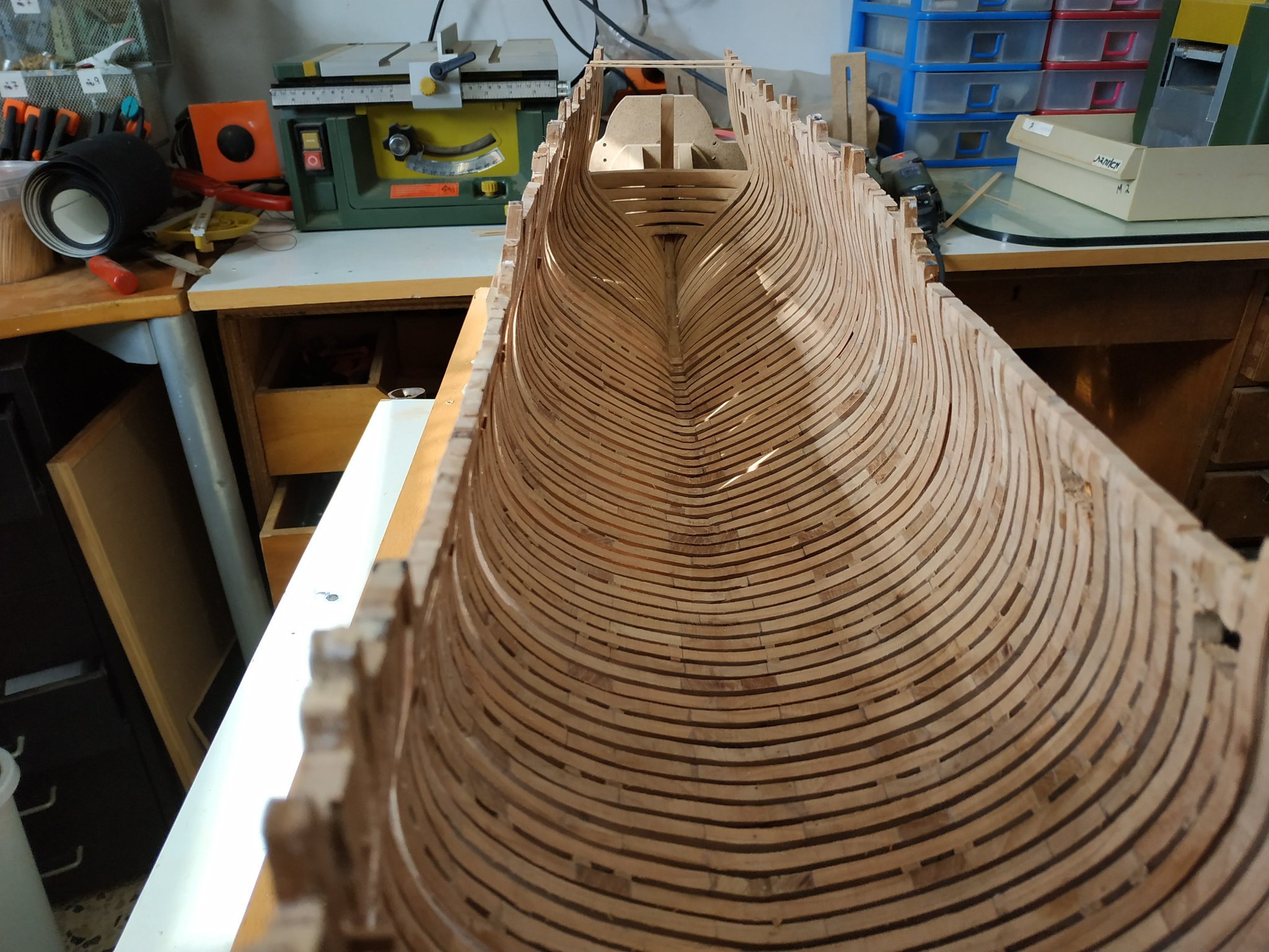
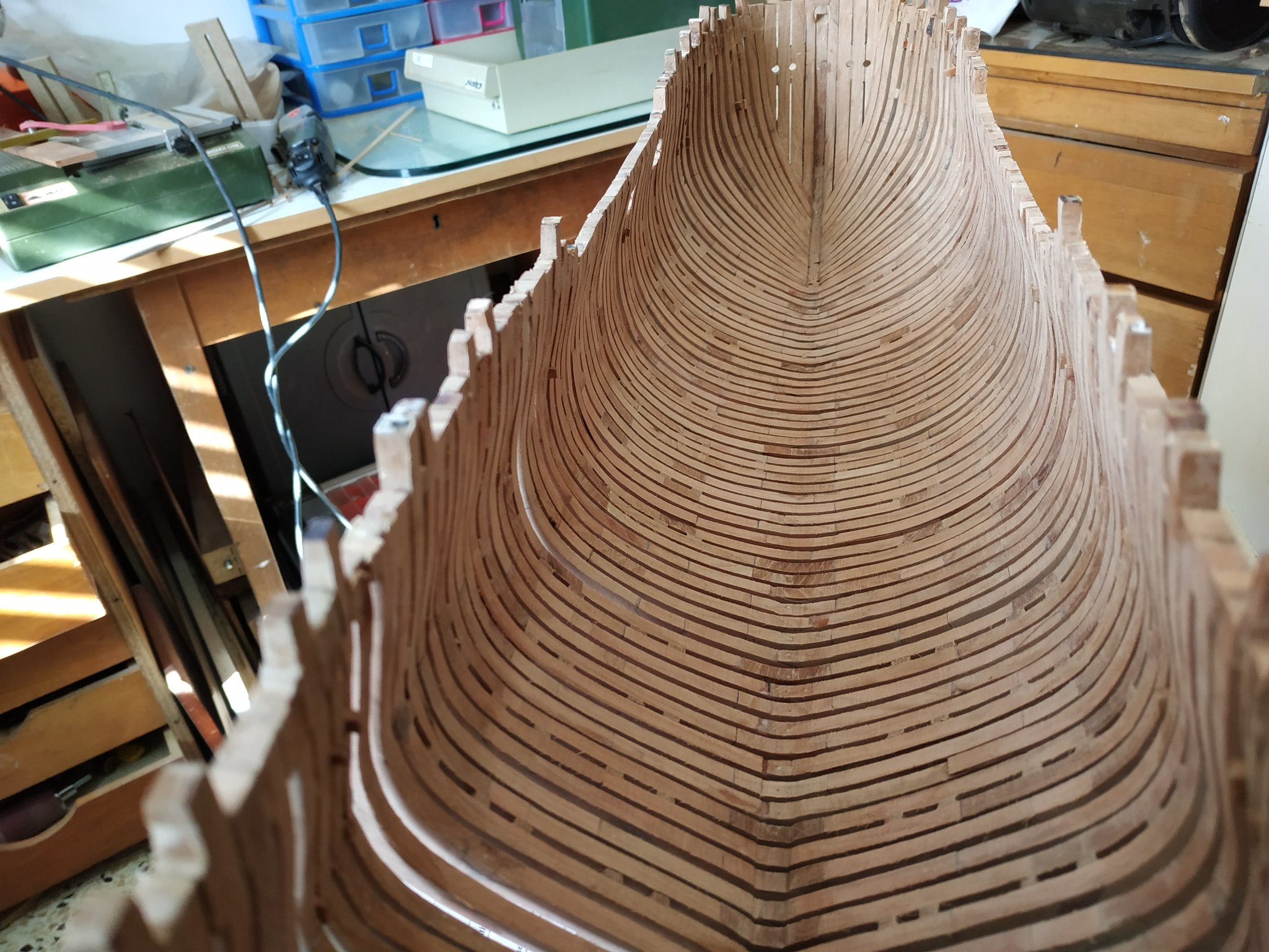
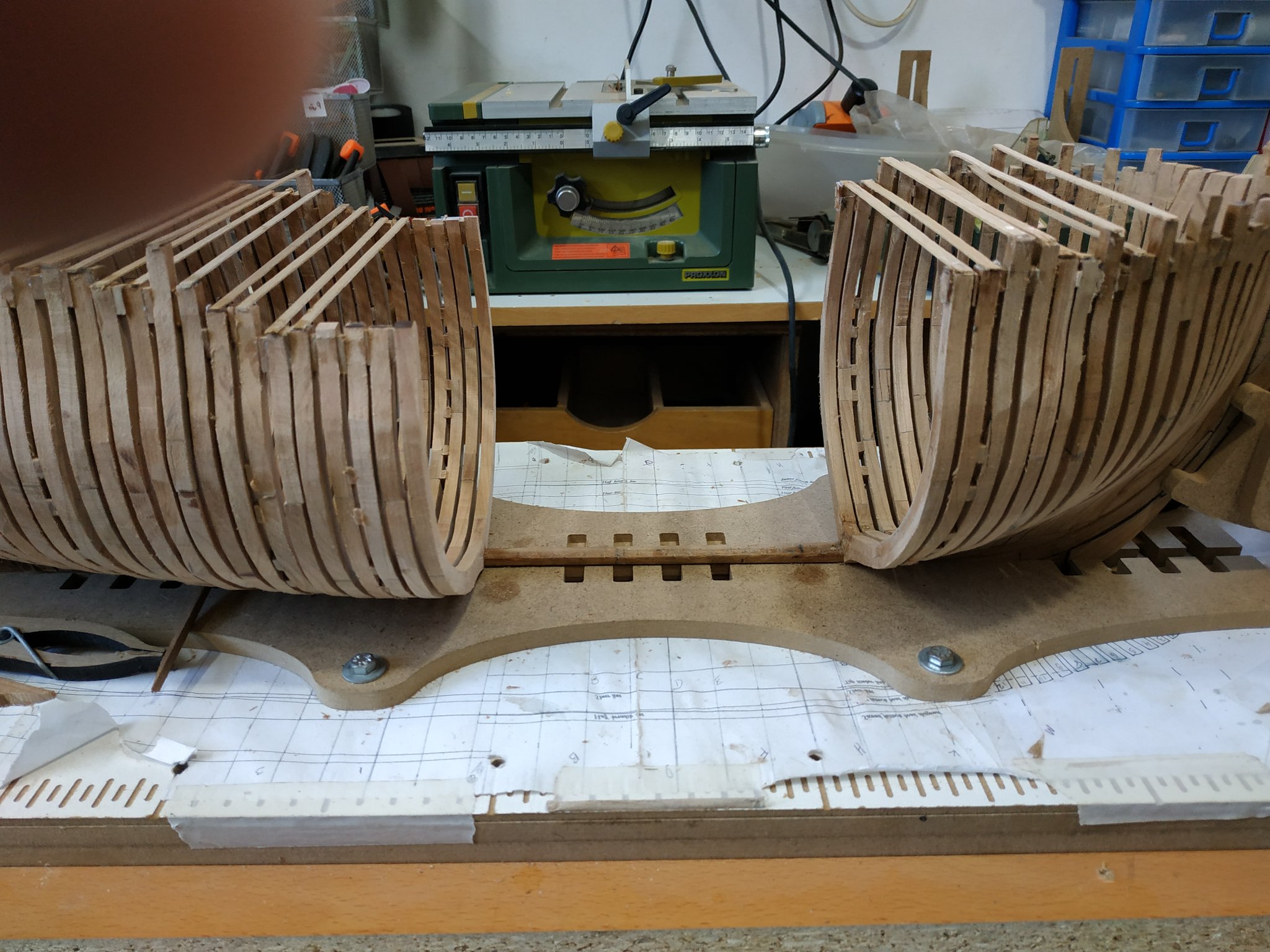
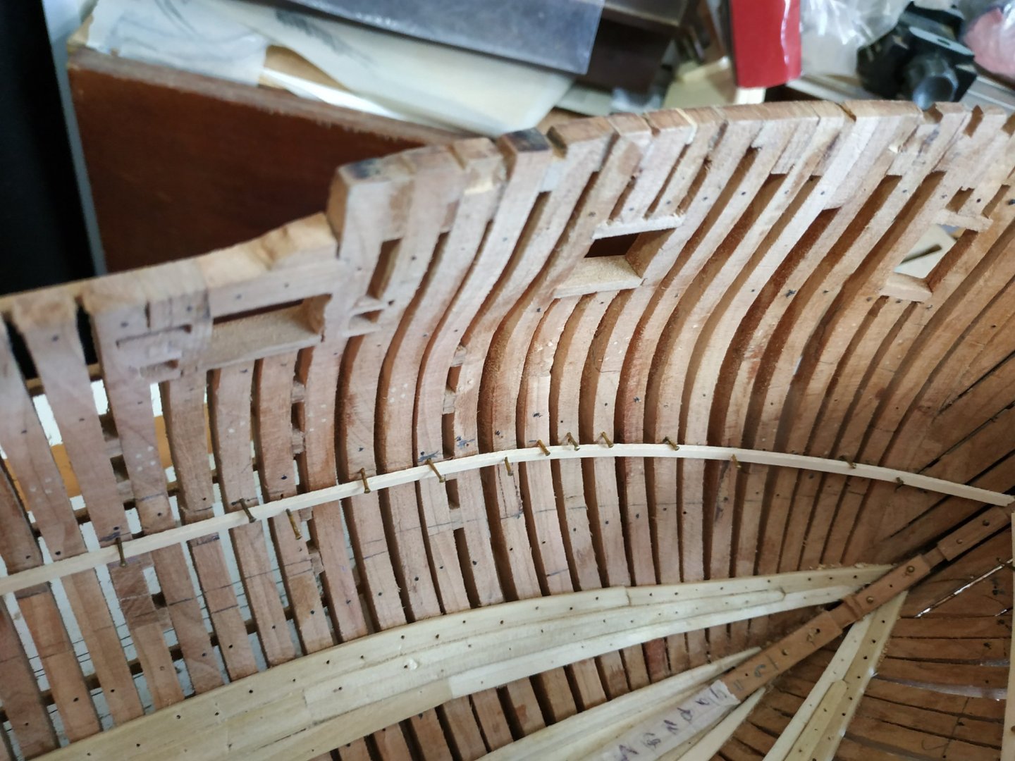
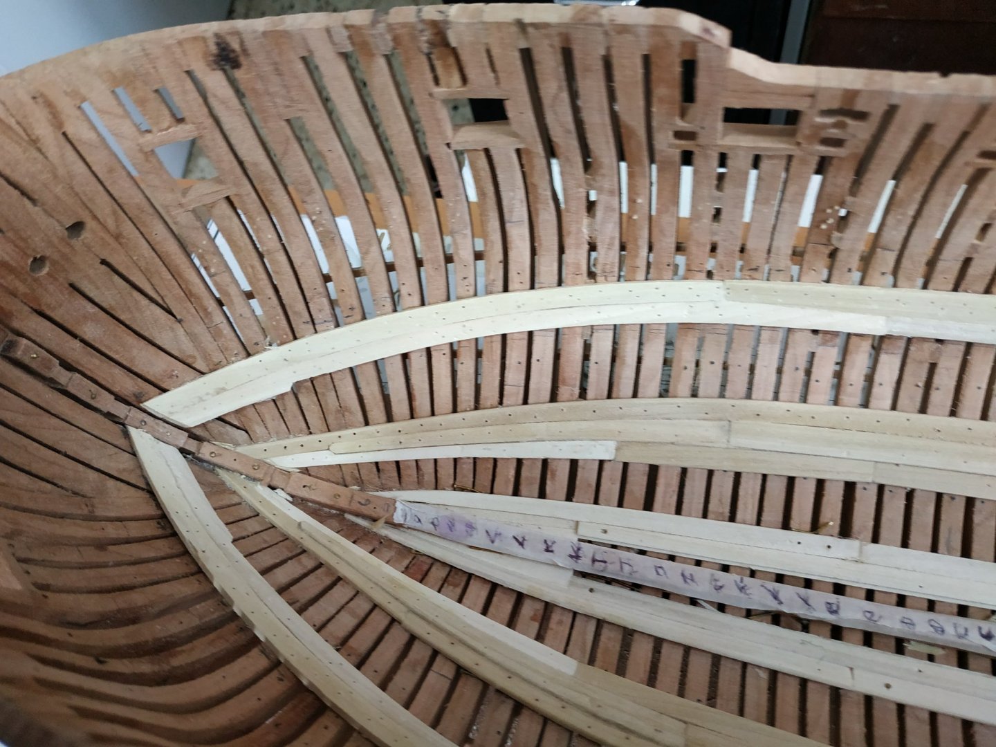
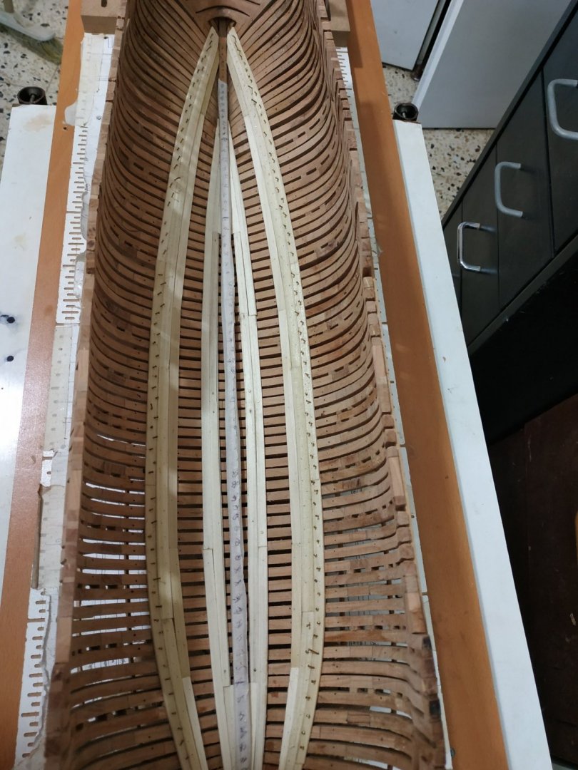
And now for something completely different-a change from framing- The Limber Strakes - a pair “planks” the lowest lining of the hull,running alongside the keelson. ( Also a change of wood. Poplar, variable pale colour and soft. Probably not a good choice, but using PVA glue, I can change if not happy. ) I printed up the internal planking expansion at scale 1:48 to help position and tapering. Also stuck paper strip on keelson with stations marked as these will be often referenced. The INNER strake is 6.36mm wide and 2.39mm thick-narrowing over last 6 cms by 1.06mm. The upper inner edge has a 1.3mm square rebate (to accommodate limber boards) The other our edge is chamfered. Made in 4 lengths, fore reaches #K aft, stern on #9aft. Amidships the strake is separated by a gap of 5.83 mm from the keelson, half that ends. Triangular pieces, from outer edge to keelson, continue for 5.2 cm foreward, and 7.3cm aft. These pieces also thin down to 1.06mm at point. The strakes are also divided into 4 pieces along its length- butt joints located on stations as shown and described in TFFM. Subsequent strakes and planks have butts staggered in 3 step pattern. The OUTER limber strake. 5.3mmx1.6mm lies next to inner strake, extending to overlap”triangle” and meet keelson, with narrowing by approx 1mm over last 9cm.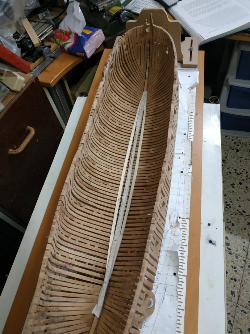
- 475 replies
-
- 11
-

-
Swan-Class Sloop by Stuglo - FINISHED - 1:48
stuglo replied to stuglo's topic in - Build logs for subjects built 1751 - 1800
The treenails are black wood (originally 1x1mm squares reduced be Byrnes draw plate) -
Swan-Class Sloop by Stuglo - FINISHED - 1:48
stuglo replied to stuglo's topic in - Build logs for subjects built 1751 - 1800
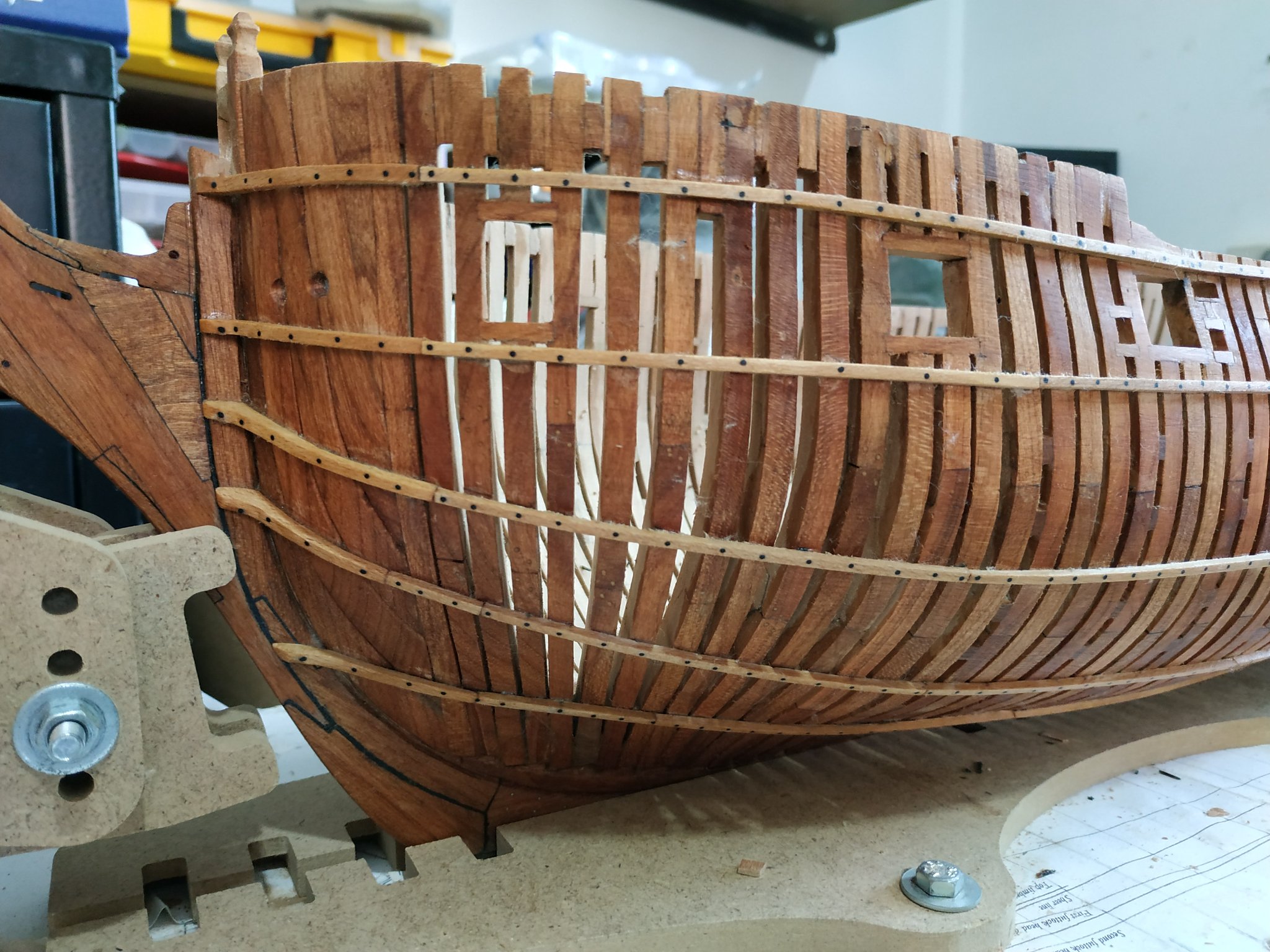
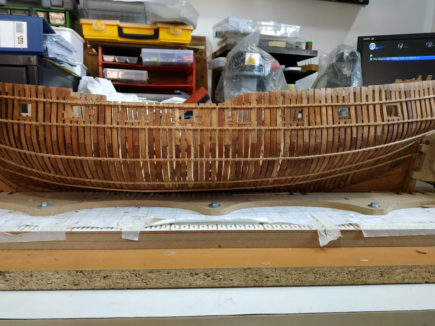
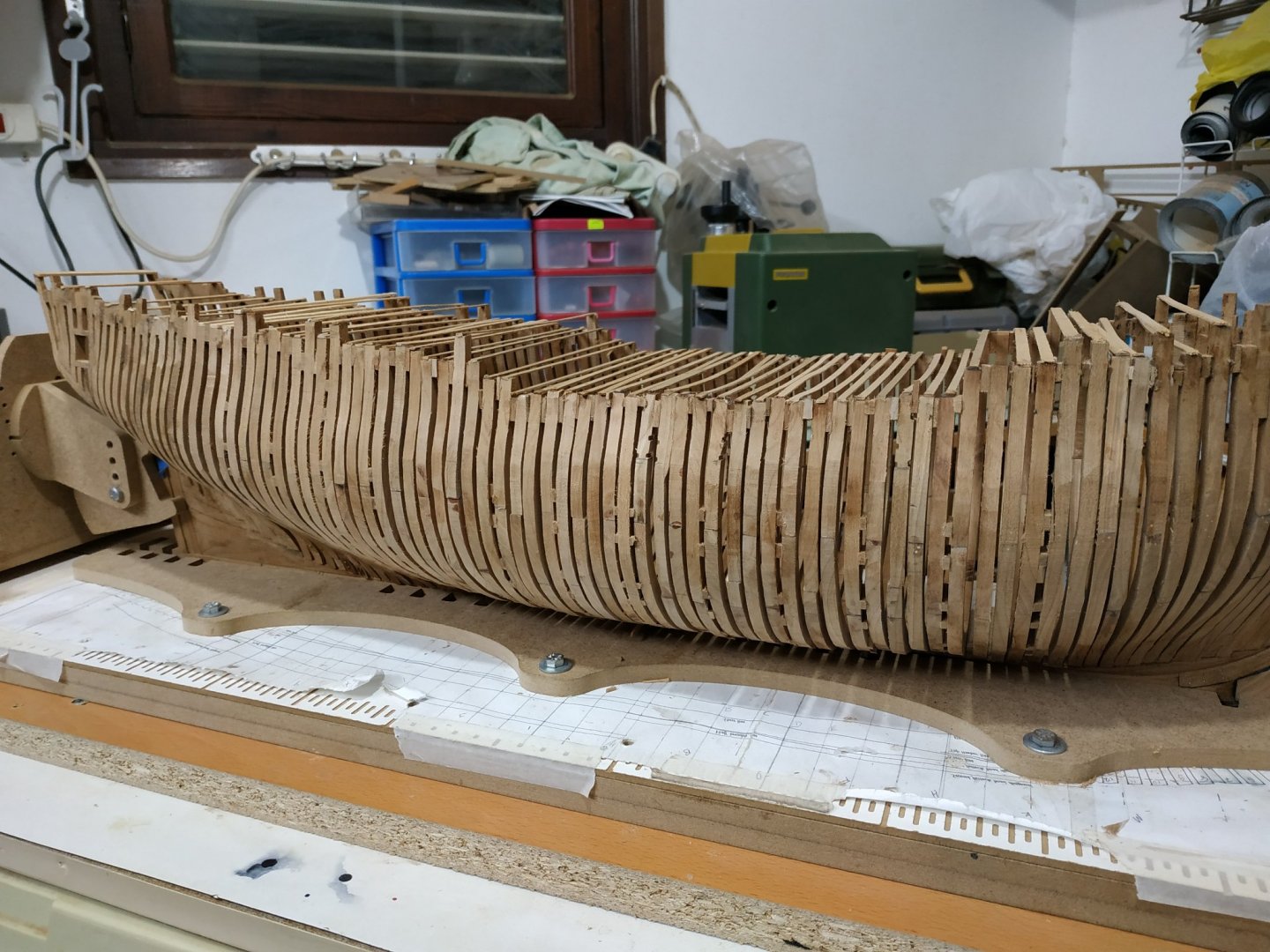
Ribbands and Harpins. First, another thank you to Kevin Kenny- by using the epoxy to glue the joints of the frames, they are clearly marked -PAV glue was invisible and needed enhancing. The placement of the ribbands depends on the line of these joints. They give temporary support to the frames while the planking is applied. I have decided to plank the inner port side and upper exterior starboard side to allow viewing of internal structures as well as the framing of the hull. It is easier to work with the hull upside down. TFFM suggests starting with lowest floor head line-lower chock line on frame plans.A line is marked at 9.5mmbelow this -extending stem to stern. The stem piece or harpin, ends in an angled “corner”, and this was made from a thicker piece and shaped to fit and after gluing in place, further shaped to merge with the ribband. Although making the ribband as a single piece gives a smooth curve, I cut to approx 10cm lengths. The next ribband is a line formed halfway between the floor and 1st futtock heads. Next is the 2nd futtock -a line halfway between 1st and 2nd futtock heads. Above is the toptimber, a line 6.36mm below the port line The top ribband is 4.77mm below the sheer line -the top of the timbers at the waist and extended for and aft to stem and counter timber. The last 2 ribbands left off the starboard side to allow for partial external planning. I used teak oil on the port side to give an idea of final appearance and show imperfections that can be attended to.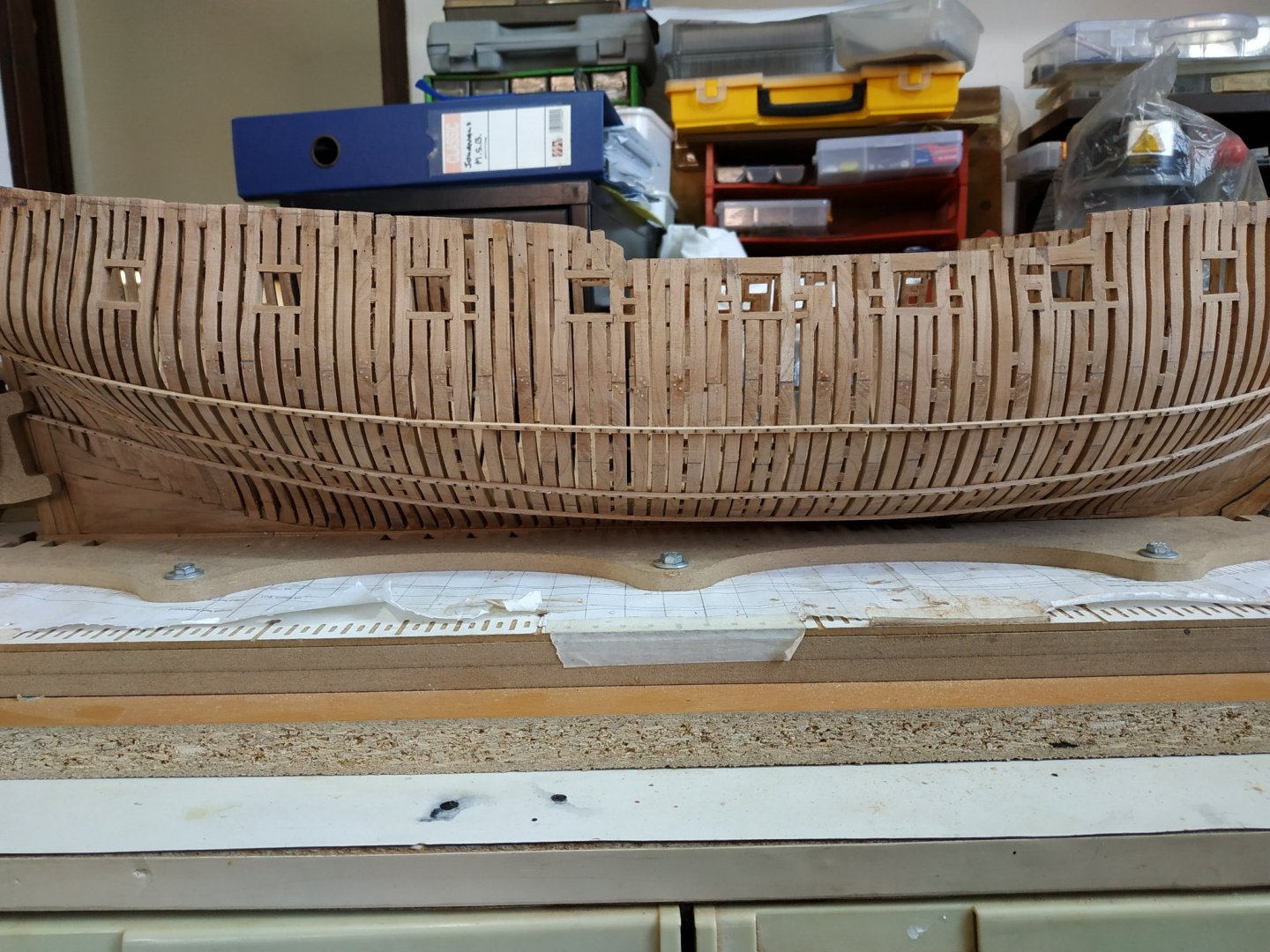

- 475 replies
-
- 10
-
-
Swan-Class Sloop by Stuglo - FINISHED - 1:48
stuglo replied to stuglo's topic in - Build logs for subjects built 1751 - 1800
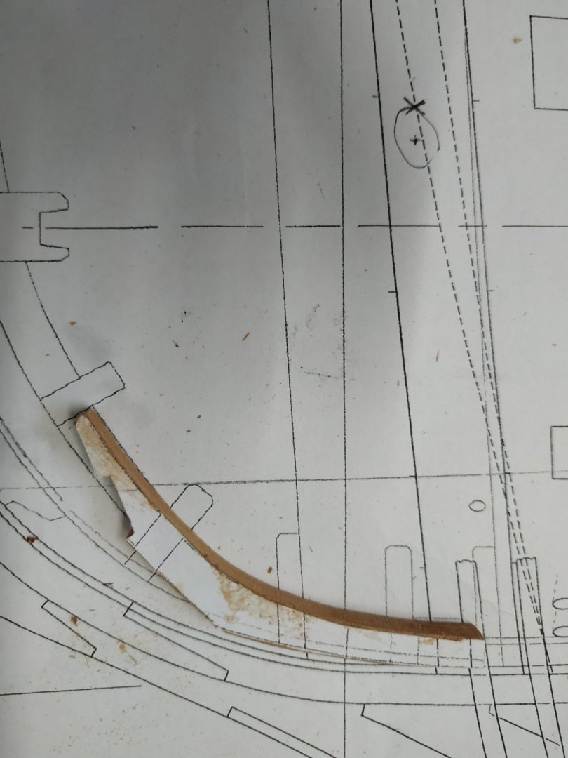
For a change from fairing- Pumps Some notching to allow pumps to reach lower into the - my plan shows situated on the aft frame #4 and fore frame of #3 either side of keel-to width of 7.5mm.Wood removed with milling bit in drill. Keelson. Good detailed explanation in TFFM. Made in 5 sections from blanks of 6.34 mm(width) by 6.89mm. Shape and position of joints are shown on the sheer plan. Using cut outs from printed copies, the resulting wood when shaped needed little correction. Joints are hooked scarphs. Dry fit before gluing to refine joint, and chamfer upper edges (1.6mm).along the length. The foremost part required some narrowing in order to fit the channel where it joins the fore extension of the keelon , called the stemson. This is made from a 4.77mm width blank. This piece is also scored on the 3 exposed surfaces in 3 places to accommodate the lower breast hook, lower deck hook and upper breast hooks. They were milled to a depth of 0.8mm and width as per plan. Similar marks on the sheer plan slightly before the keelson/stemson joint and on the aftmost section of keelson (“crutch” at station 20). As I hadn’t glued the former yet, I decided to add it, in case needed later. Decided to use some brass pins as securing bolts- big mistake as messed up some.(despite “pusher” some bent or not centered). Will rectify another time when I work out how to remove them without damaging the wood..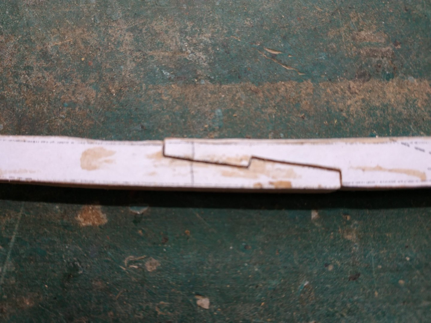
-
Swan-Class Sloop by Stuglo - FINISHED - 1:48
stuglo replied to stuglo's topic in - Build logs for subjects built 1751 - 1800
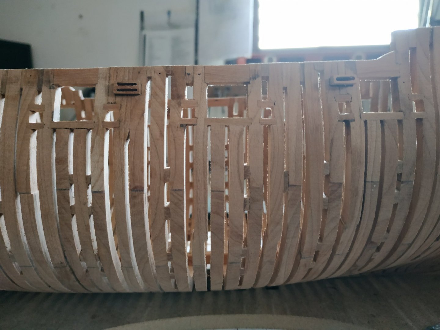
Openings for fixed blocks. Amidships, double block fore of gun port 5, single block aft of gun port 3. Upper margin in line with upper margin of ports. Width of both 10mm, height of double 4.7, single, 3.6mm. I replaced the spacers above the respective sweep ports to close the gaps between the frames and strengthen the opening. I don't have suitable brass rods or the ability to make the small discs to represent the shreeves. Cutting very thin slices( less than 1mm) of wood from a dowel similarly seemed too difficult. So I took some old thin planking strip 6mm wide, cut 8 approx., squares and stuck one on top of the other. A 4mm rod stuck to one end for the chuck to grip on, and when dry, turned to column against a sanding stick. When rounded to size, 7mm diameter, soaked them in some alcohol to seperate them and colour black with felt-tip. TFFM says the thickness of single and lower of the double is 9.3 mm, the upper0.5mm. A couple of passes with a file reduced it slightly, but I’d forgotten to make the upper slit of the double block narrower in any case.( I don’t know if I’ll remake them or not). Rather than a sandwich of several pieces, I milled out the blocks from solid pieces. The depth of the blocks are more than the thickness of the hull to allow for planking, so I made the blocks with an extra 5+mm depth and unglued, for later adaption and fixing.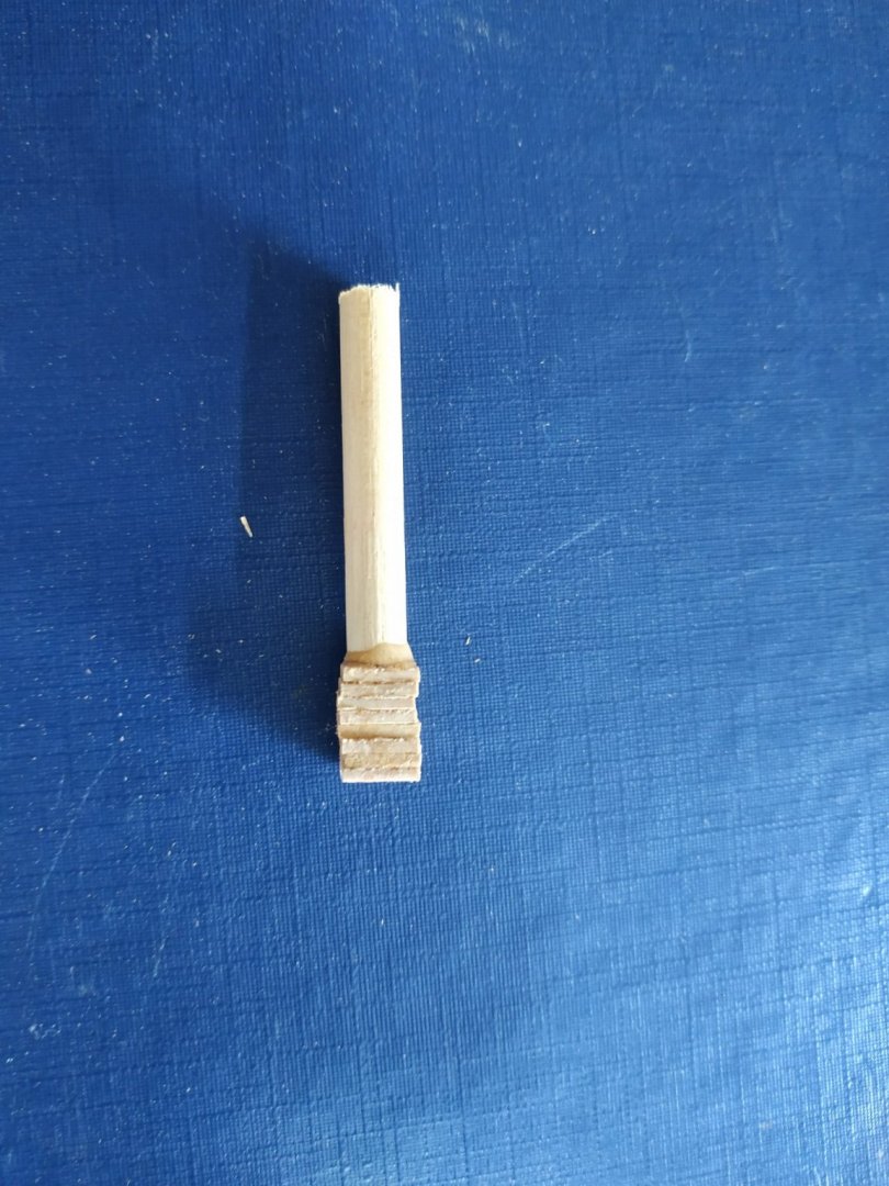
-
Swan-Class Sloop by Stuglo - FINISHED - 1:48
stuglo replied to stuglo's topic in - Build logs for subjects built 1751 - 1800
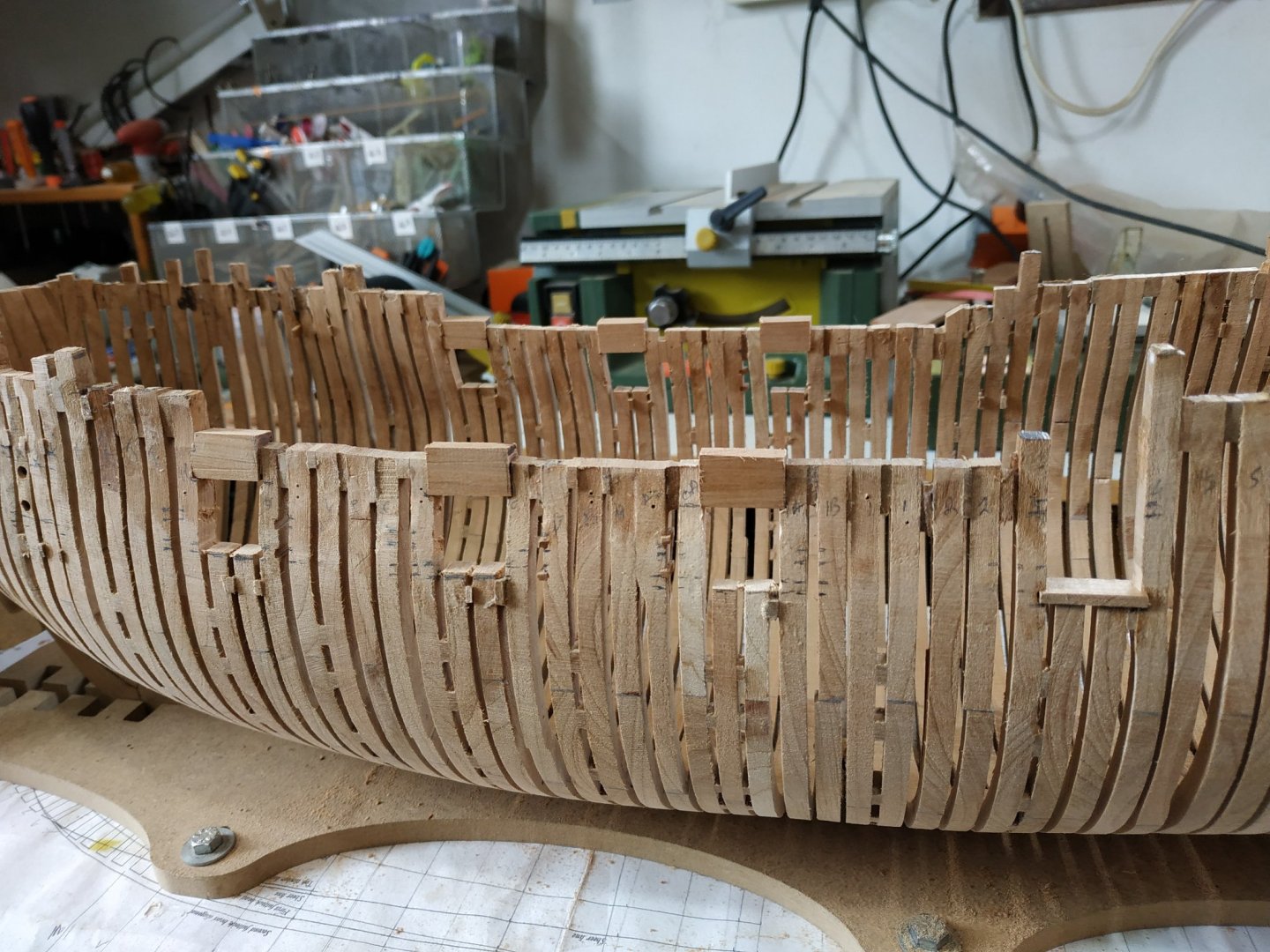
Ports-opening and fitting mortisses. Leaving the finer fairing for later, moved on to the ports. (Gives a rest to the shoulders and breaks the monotony.) Using the sheer plan, take measurements for the openings using the build board level as a base line. To minimise confusion and mistakes, mark out the stations on the top of the frames. Tried various methods including a proper waterline tool(surface guage)- but found ruler , perspex block spirit level + horizontal eyeballing, the best for me. The base measure is the lower line of each opening, which is the upper level of lower sill. The gun port sills are 2.65mm thick, sweep port’s -2.27mm. The line is parallel to the gundeck level.It also forms the upper level of sweep ports.They are not horizontal. For example, starting with the central frame “o”-the lower sill top is 11.05mm on my plan. The line for the bottom of this sill is 2.65 LESS. With a vertical gap of 14.3mm, the lower level of upper sill is 11..05+14.3, and its upper level is another 2.65mm MORE. I cut a 1mm deep notch between the makings for seating the sill. (micro saw and file) I tried the angled sill fitting as per TFFMon some scrap but it was beyond me. Making these markings and the care required for accuracy emphasised that measuring and making at an earlier stage would have been a mistake. The couple I did, needed filling. **Amidships, the sill hight extends to the tops of the frames.** I marked all the gun ports and made them alternating port and starboard. I made the width of the sill to fit as there is a slight difference in the space between frame, even though it was supposed to be 15.11mm. The sweep ports have a thinner sill (2.27mm)and as the lower line of the gap is the same, the lower line of the notch, is 11.05-2.27mm- in this “O” example. (seems complicated on reading, but is simple on doing) These sweep ports are 4.24mm square- the upper sill is marked as 11.05+4.24 and another line another 2.27mm. These were similarly notched at 1mm depth. As discussed some weeks ago, the frame spacing does not allow for a width of 4.24mm. Therefore, the space is formed after the sills are fitted. I.e. Sills made at width of 6.24 and the depth of the notches made to accommodate this. Then the gap between the frame is widened to the required 4.24mm (Not symetrically- one side or other looks “better”) More fairing of the new “inserts” and remove the temporary extra spacers. Looking better I think.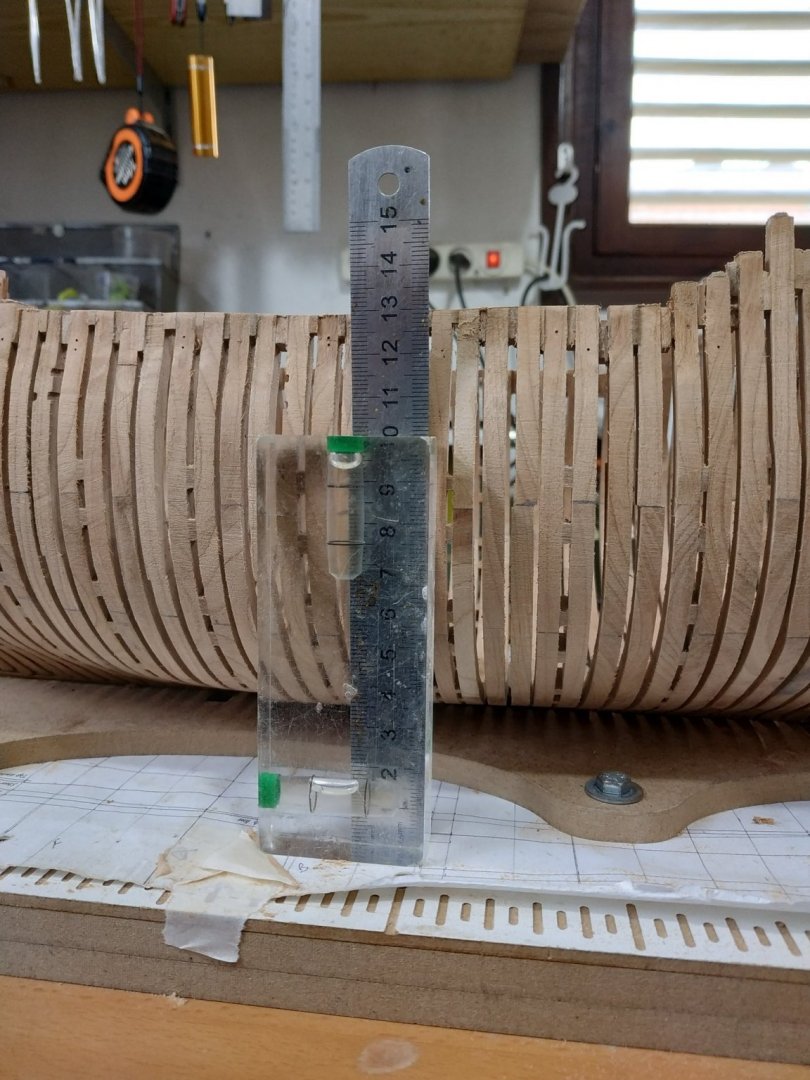


- 475 replies
-
- 11
-
-
maintains an impossibly high standard. Inspirational and much "how to"
-
Swan-Class Sloop by Stuglo - FINISHED - 1:48
stuglo replied to stuglo's topic in - Build logs for subjects built 1751 - 1800
-
Swan-Class Sloop by Stuglo - FINISHED - 1:48
stuglo replied to stuglo's topic in - Build logs for subjects built 1751 - 1800
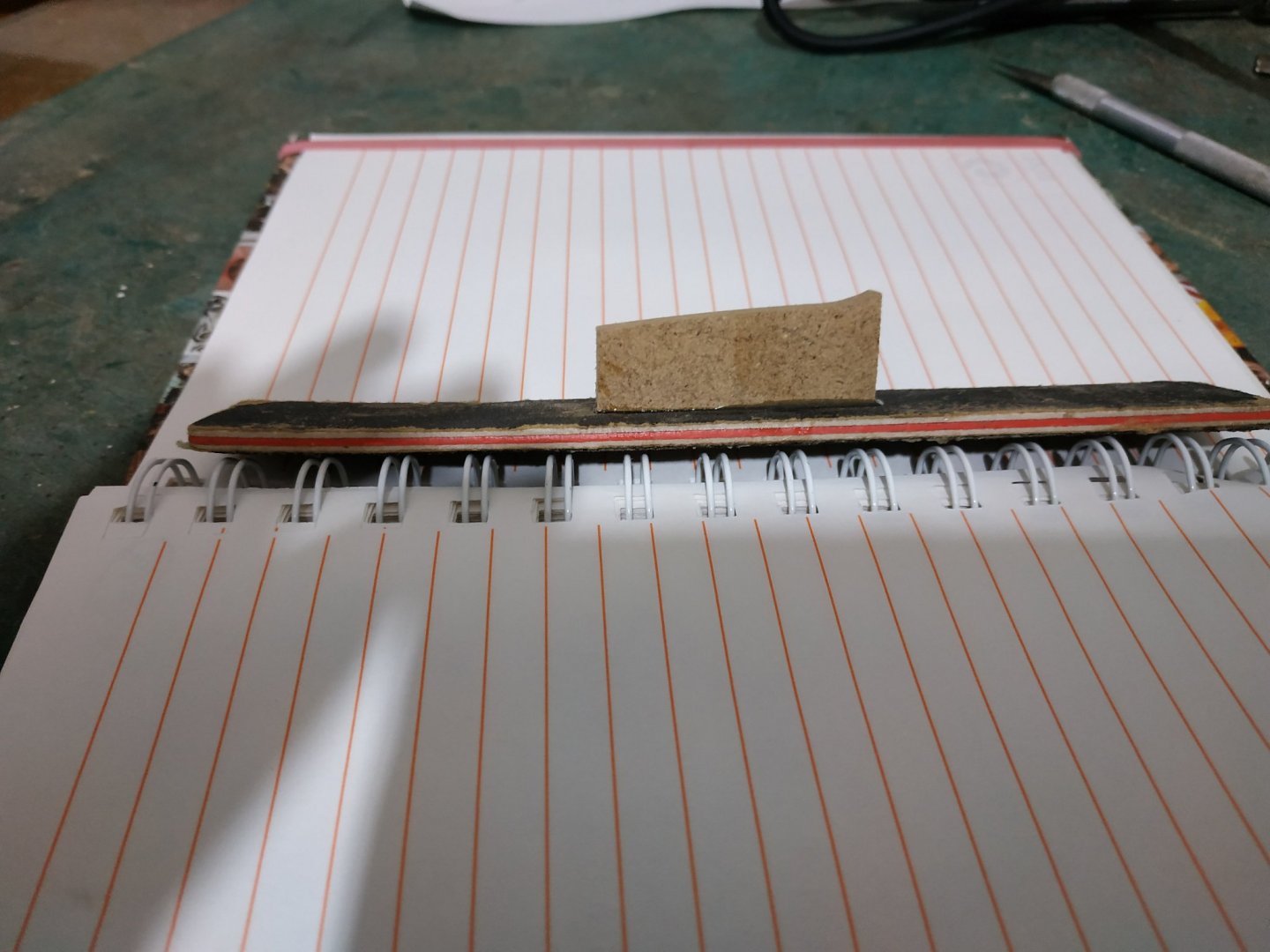
"Here is an example of sanding stick: The sandpaper is rubber-cemented on the lower side of the thin, flexible batten, so is easily replaced." Inspired, I took a well used emery board (nail file) from one of the cheap beauty care shops and it works very well with a piece of broken belt sanding strip. Throw nothing away! -
Swan-Class Sloop by Stuglo - FINISHED - 1:48
stuglo replied to stuglo's topic in - Build logs for subjects built 1751 - 1800
Now I understand. Long and and rigid didn't work well on the inside. -
Swan-Class Sloop by Stuglo - FINISHED - 1:48
stuglo replied to stuglo's topic in - Build logs for subjects built 1751 - 1800
Not quite sure what you mean. Any pictures would be welcome. -
Swan-Class Sloop by Stuglo - FINISHED - 1:48
stuglo replied to stuglo's topic in - Build logs for subjects built 1751 - 1800
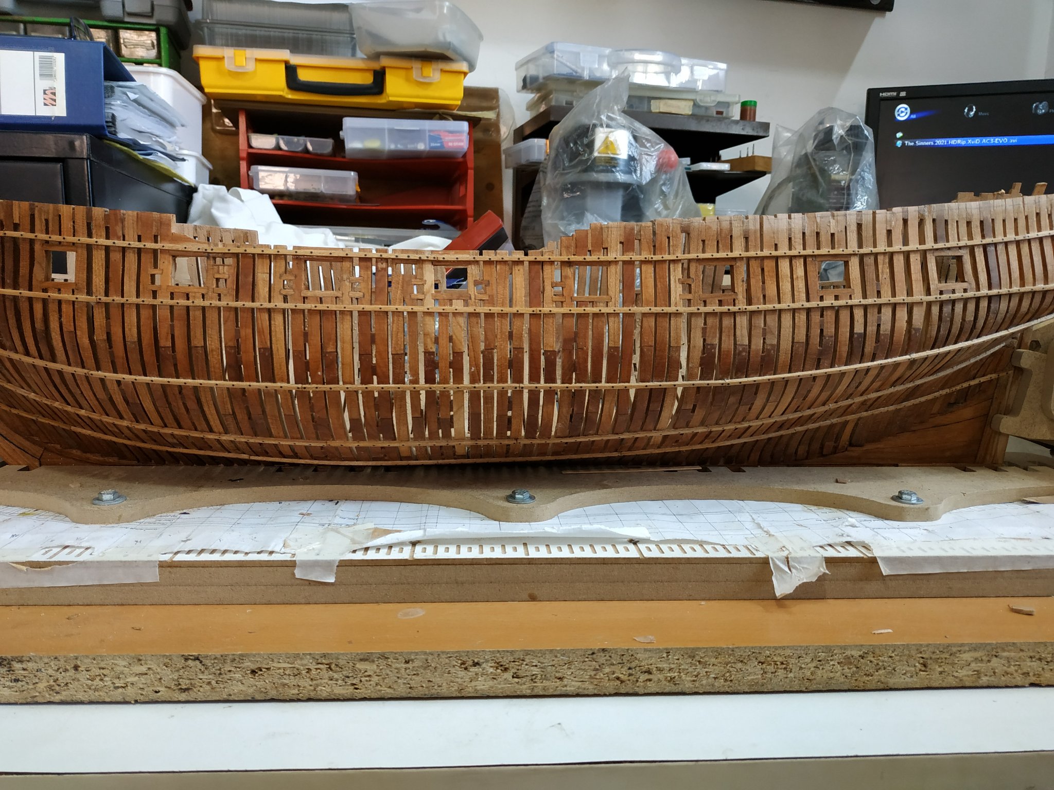
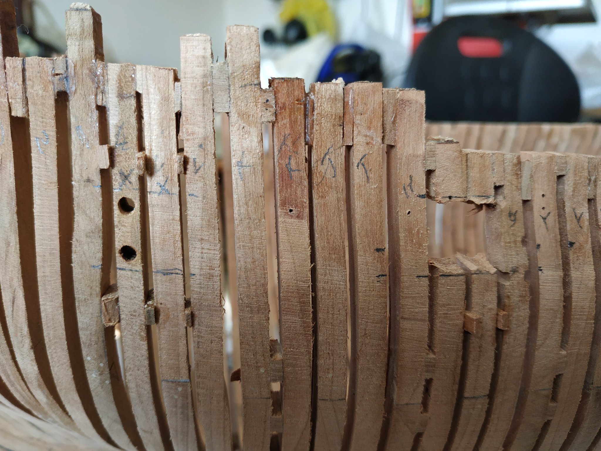
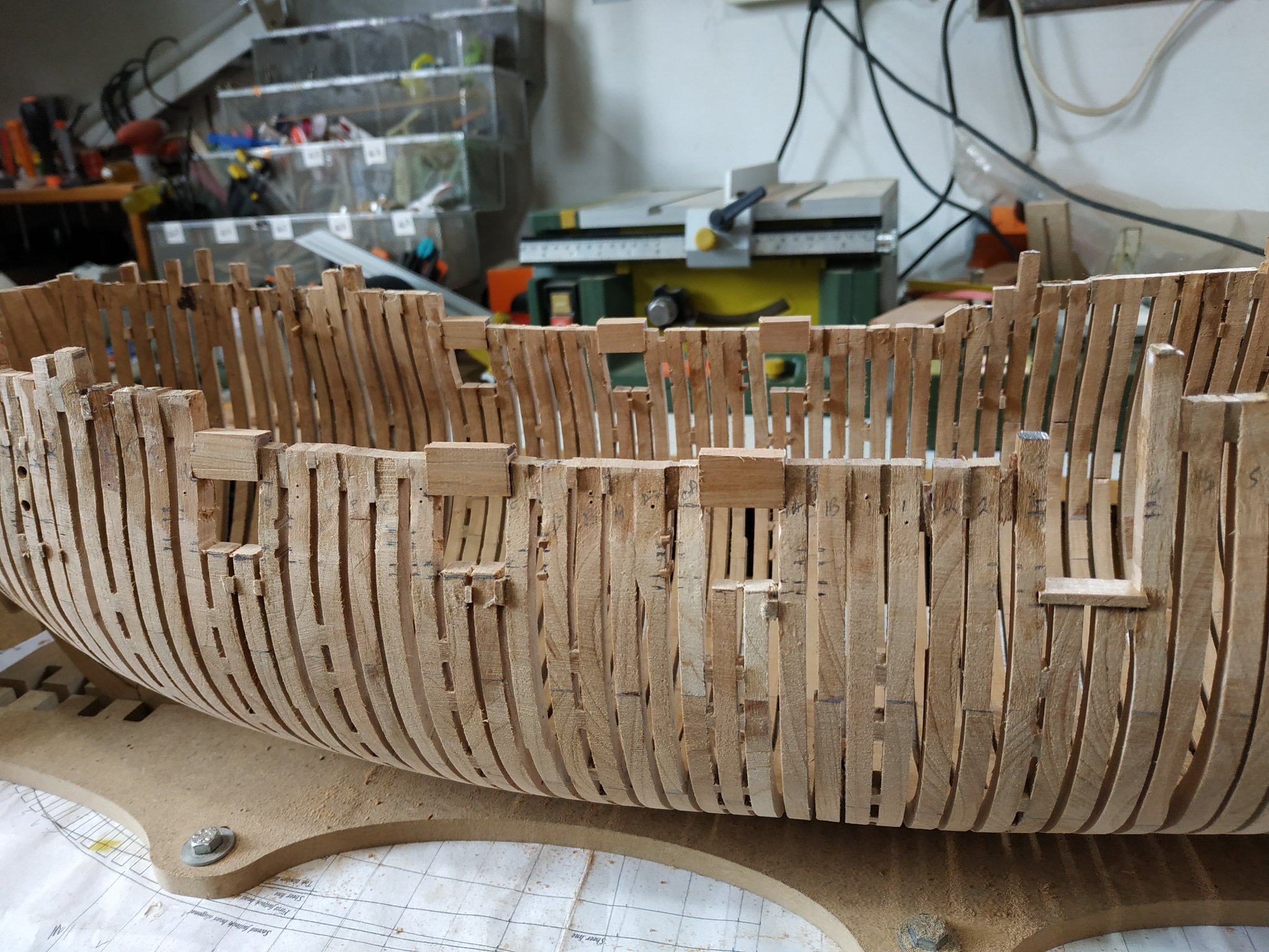
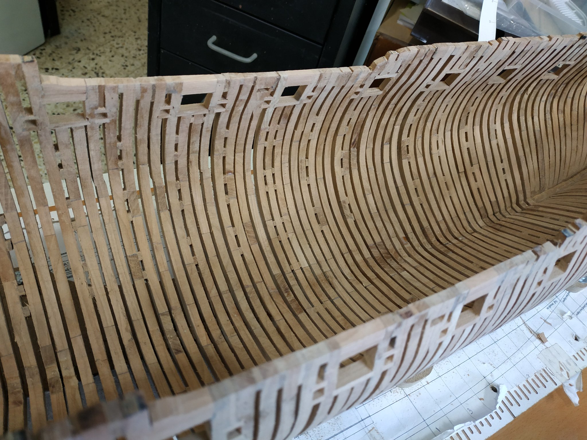
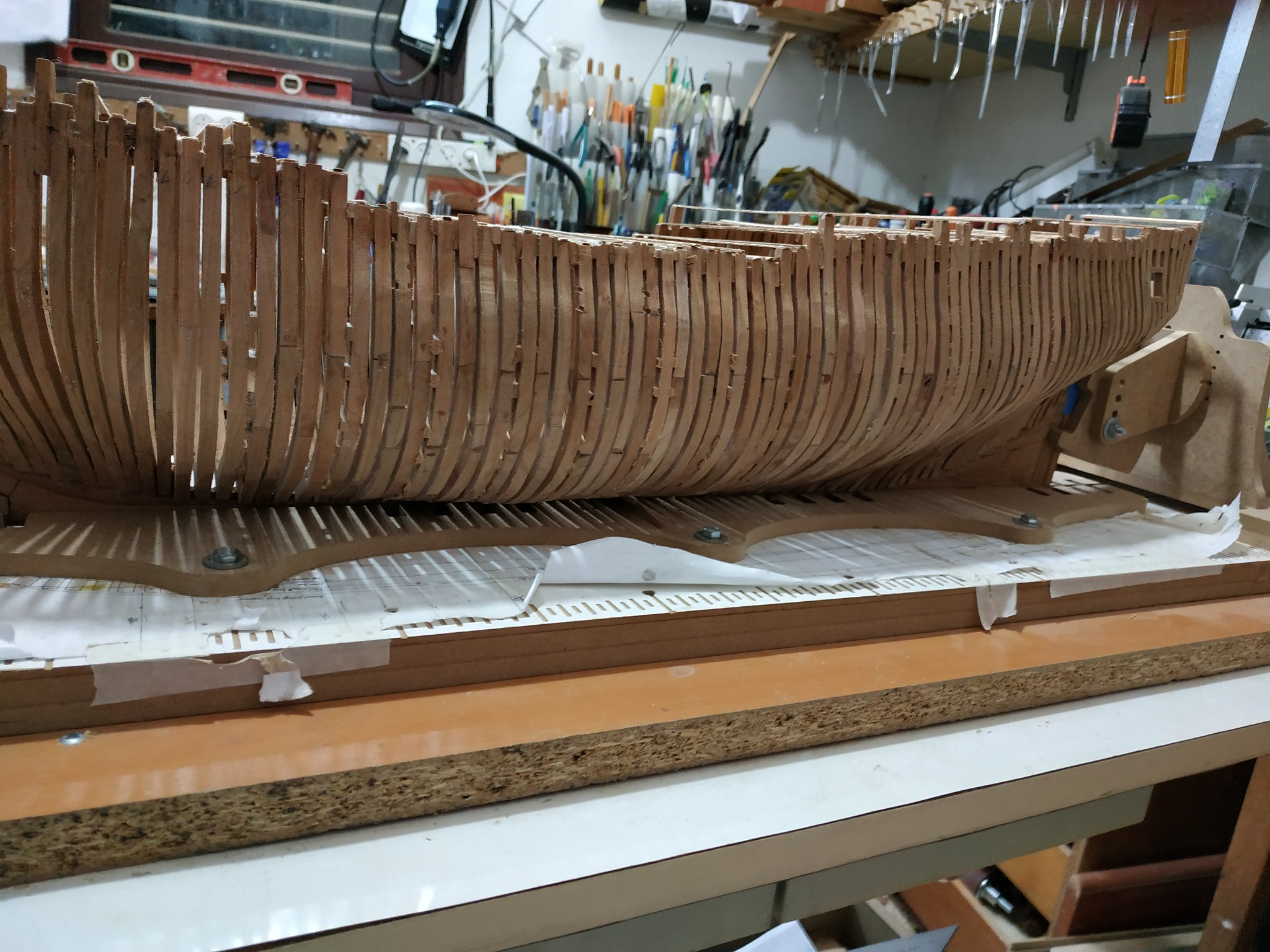
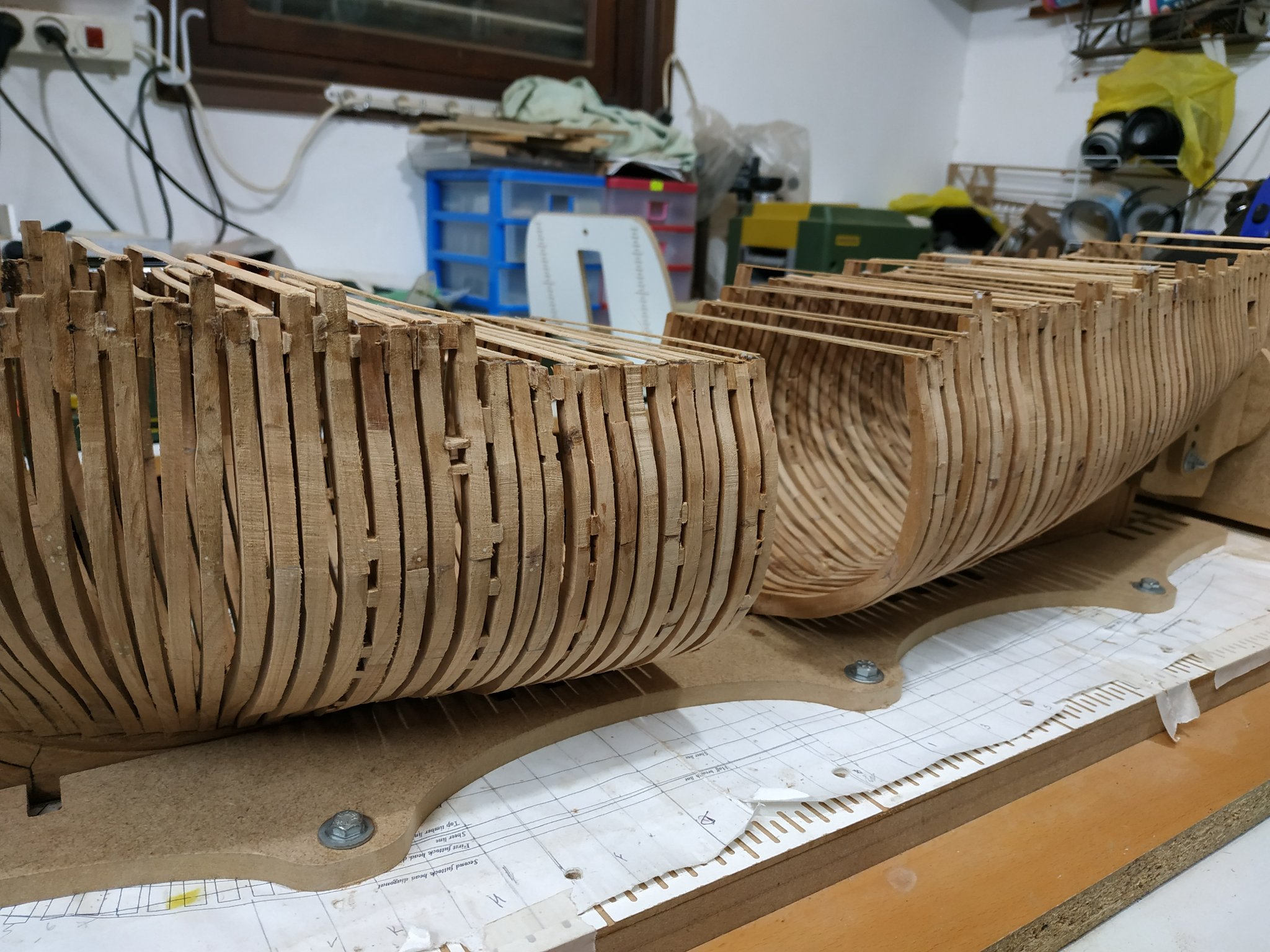
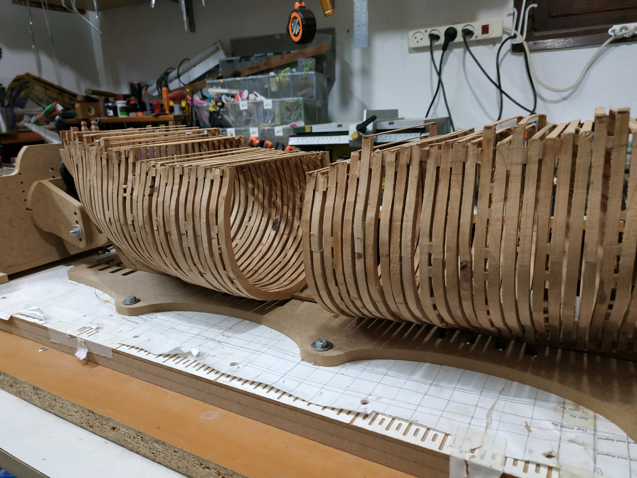
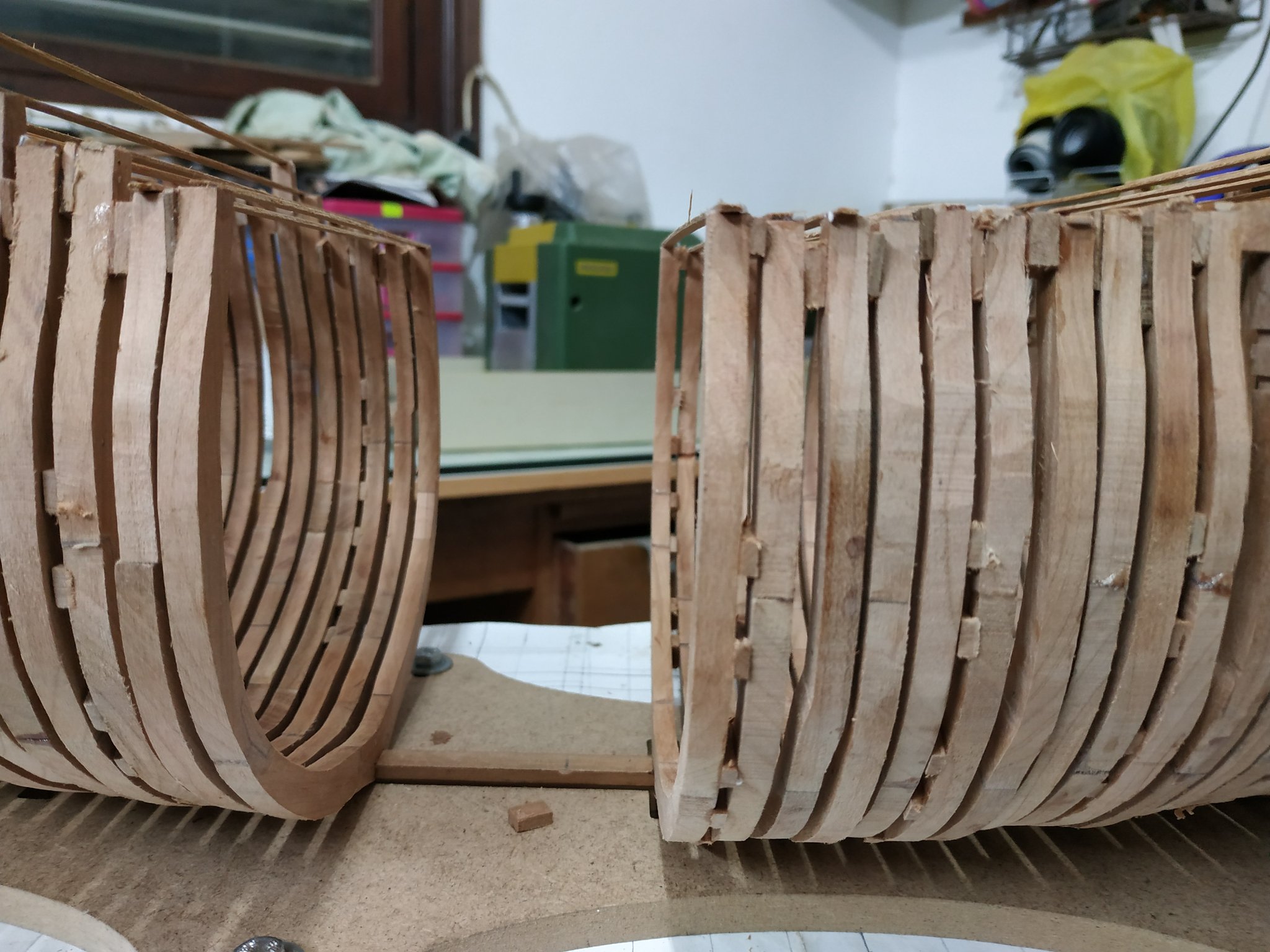
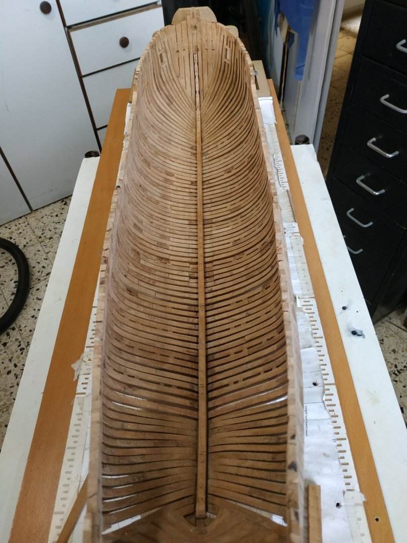
Fairing the hull This is THE most frustrating and boring task in POF model building. With POB, only need to do the outside of the hull, which is much easier. This is my 3rd POF so I knew what to expect. For those who complain about ratlines, believe me that tying those knots are an erotic experience when compared to fairing the inner hull. A more accurate forming of the frames could reduce this, but with so many variables, more mistakes and consequent rebuild would be necessary. The whole structure is unstable, anchored only at keel and top of upper futtock .The spacers between the upper futtocks still occasionally separate despite reinforcing the glue with treenails. Starting with the outer shell -easier access and less curves, and allowing the strengthening cross stays to remain in place. Immediately, the center O frame broke and was remade. I placed a baton (temporarily) about the upper hull for added rigidity. Fitting this with some brass nails seemed the easiest solution. Referring to the half-breadth line, reduces worries about removing too much. The inner hull has various curves which demand a variety of solutions for sanding, but mainly short, curved and narrow sanding blocks, and loops of sandpaper strips wrapped around the knuckles. As I said, boring and frustrating.


-
Electric sanding belt file
stuglo replied to Don Case's topic in Modeling tools and Workshop Equipment
I have used my Proxxon BS/E almost daily for the last few years. When it broke, I ordered a new one immediately. I was able to have it repaired so now I have two and sleep more easily. Both hand held and clamped in a vice (via adapter) it is very useful for coarse or crude shaping and finishing. Difficulty in maintaining right angles is a drawback so ample allowance must be made. The "bow" side is good for gentle curves. I used it for tapering, beveling and initial fairing for the outside of the hull The finest paper is only 180 grit but the "aggressive" nature of the tool precludes its use for fine finishing. I'm in the middle of fairing the inside of the hull and it is of use only for the tops of the frame. So far, no substitute for elbow grease. PS I have a Wen spindle sander- seems pretty good. In truth, almost nothing is as well made as it was. Robots have no pride in workmanship and the "bottom line" is all important. On the other hand, my grandparents first colour tv cost the same as a new small car. -
Swan-Class Sloop by Stuglo - FINISHED - 1:48
stuglo replied to stuglo's topic in - Build logs for subjects built 1751 - 1800
You flatter me. I'm 72 and work part time -
Swan-Class Sloop by Stuglo - FINISHED - 1:48
stuglo replied to stuglo's topic in - Build logs for subjects built 1751 - 1800
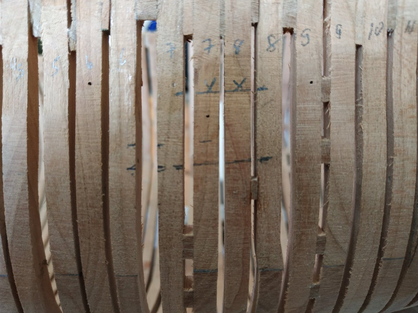
#B A pair of bend frames, but they are shown on framing plan with a larger number of spacers (but the but where this should happen is not so marked) I assume this is a mistake. Spacing foreward must allow for a sweep port. The narrowing gap between this pair and #2 is important so as to allow remaining frames to be placed with appropriate spacing. Measured and calculated several times, the gap on the keel seems barely to be enough . #A fore-regular Aft a shift forward which at its upper futtock, widens to close gap to neighbouring fore#1. This is to accommodate a pulley block above the sweep port (to be inserted later). I used a wider (7.3mm)blank and milled the aft part for the shift and lower fore part so the upper part remaining closed the gap to the next frame. # The remaining frames : Some confusion with the order/numbering. With various hints and referral to the framing plan, it seems the order is (going forward) :- Pair #1 (bend), #1B, #1A, #1O,#O (center) #AO, #A1 #1B - shift aftward and sweep port recessed more so gap to next frame is narrower than usual # O- thinner frame -4.77mm-and each joint is framed by spacers on either side (also narrower than usual). The frame plans suggest fixing the first to the frames fore and aft (#O1 and #OA) but I felt easier to match by fixing the to both sides of #O. Note these three all have cross chocks as bases. Spaces between these frames are also narrower and as I seemed to be running out of space on the keel, made them at 1.60mm. Nevertheless, when I dry fitted the last few frames I lacked 4mm. Not much, but the crowding was unacceptable. One cause was the extra width allowed for the sweep ports until I learned that they were “countersunk” or recessed. Anyway, some of the frames were not very good and I’d already made some other gaps too narrow. Most of the problems were among the lettered frames ( that dyslexia again). I removed most of the frames (alcohol) and remade completely 3 (#J,#H,#F) Changed the casts to shifts where I had earlier made mistakes. After a couple of days of remedial modelling, all fit with the appropriate spacing. 8 months of work -frustrating and satisfying- much progress in understanding and craft, but a landmark. Still to make ports, fairing etc and still on ch 3 vol 1 (of 3), but a landmark nevertheless. IF I CAN DO IT, SO CAN YOU!!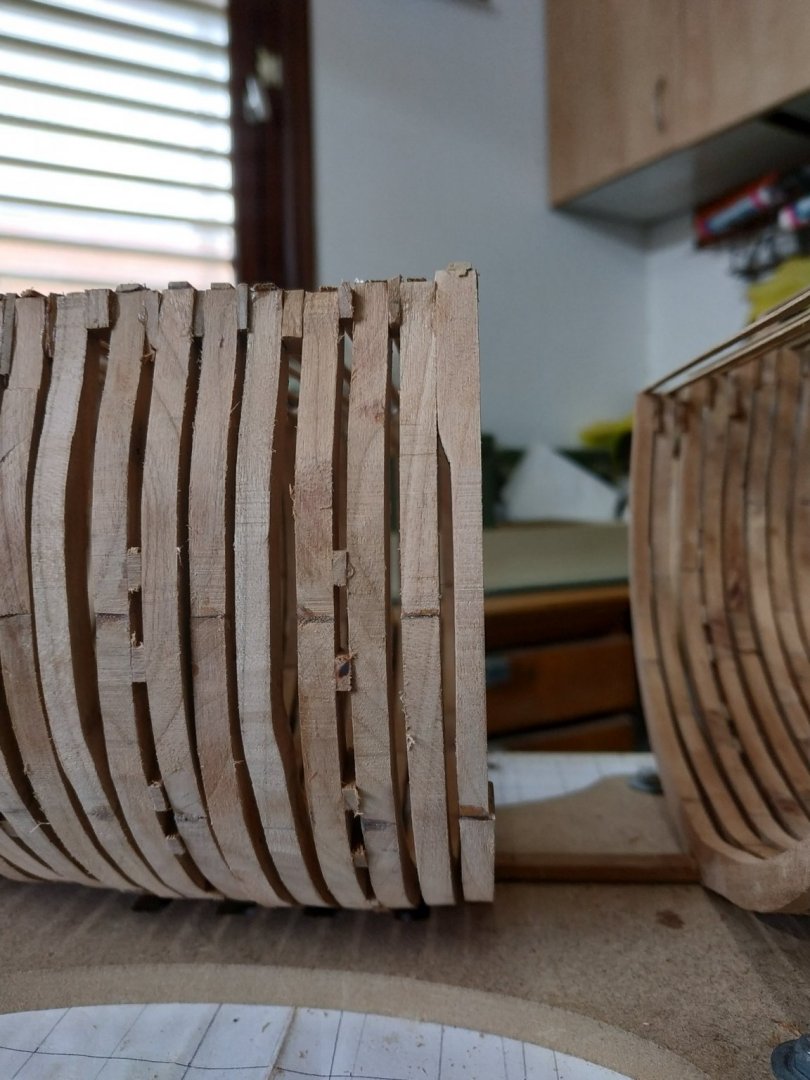

- 475 replies
-
- 13
-
-
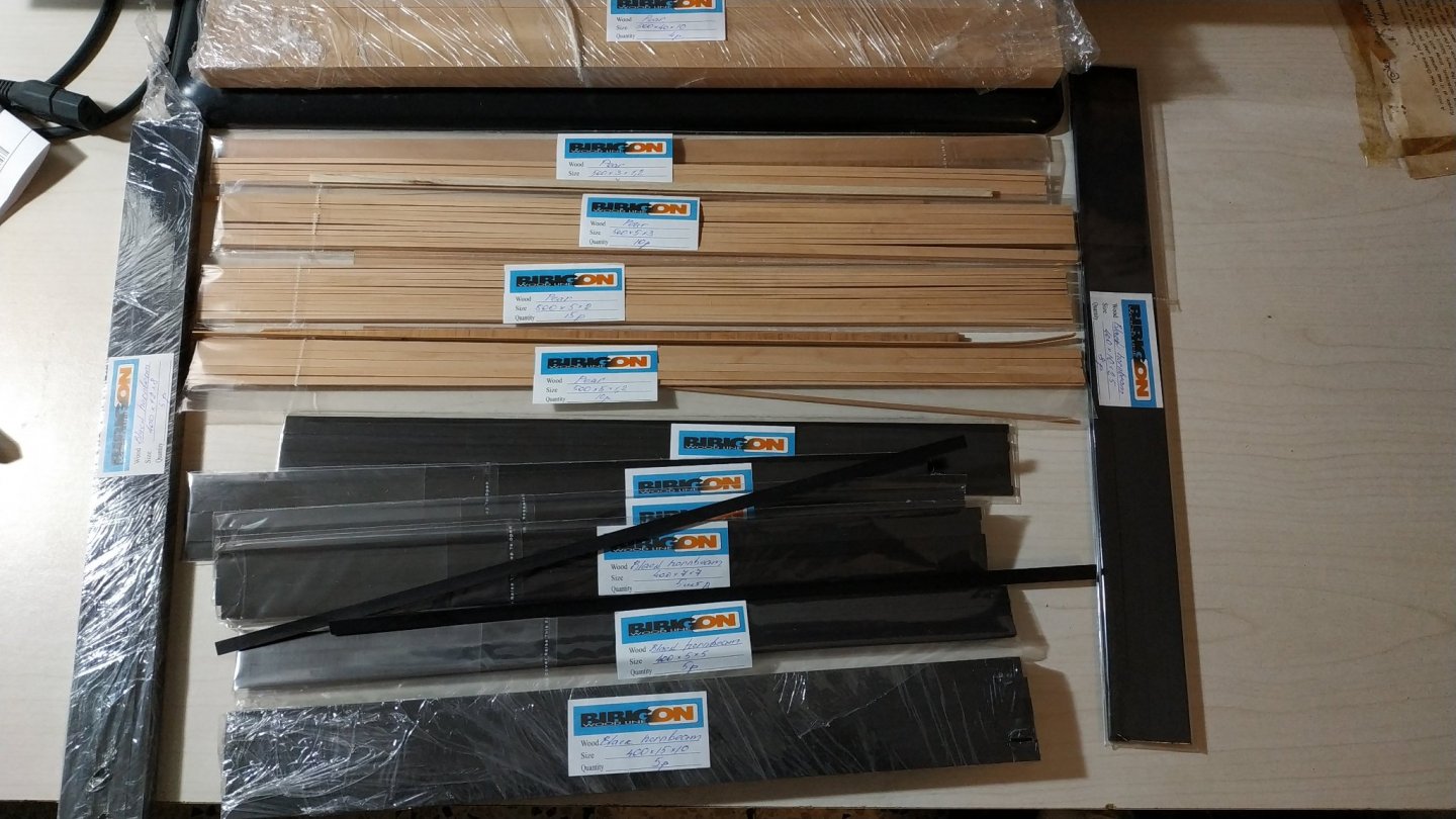
I would like to add my praise of Sergey at Bibigon in Russia. I received my first batch of pear and black hornbeam and quality is fantastic. Price is fair, delivery within 2 weeks and service is polite and professional. We communicated in english and emails were answered within 24 hours.
-
Swan-Class Sloop by Stuglo - FINISHED - 1:48
stuglo replied to stuglo's topic in - Build logs for subjects built 1751 - 1800
Return to lettered frames. #F- my framing plan seems to show a thinned fore face of the fore upper futtock to allow for sweep port. Decided again to postpone mortesses until framing completed to avoid height issues.( Although using the mill before fitting, mistakes may necessitate remaking frame. #E- no shift mentioned, but will need one aft to accommodate another sweep port. #D- In order to allow sweep port foreward and gun port aft ,fore D is straight ie without shift, a wider 3mm space needed between seats of #E aft and #D foreward. #D is also a bend pair-spacers required. #C-aft has forward shift for port . The distance between these frame determined by port width and therefore between #Cfore and #Daft, only 1mm.Between #C’s, 2mm NOTICED MAJOR ERROR. The earlier shifts were cast i.e.dog leg. This was employed incorrectly on some frames such as #G. I think I can correct this with a file while frame attached- I don’t particularly want to remove and rebuild. #B- spacers On framing plan, more and different pattern, but same plan doesn’t show anything special either side of the central #0, which is clear on individual frame plans of TFFM. Will therefore continue pairs of spacers as before. Return to numbered frames. ANOTHER MISTAKE. My reference mark on frame/plan is now obscured, and some movement seems to have occurred. Premarking frame placing is difficult as this is determined as the build develops. Using the aft point of keel and joints near the stem, gives some discrepancy. I can’t understand why. I've checked multiple times. Difficult to blame expansion or contraction of wood. The difference is only couple of mm, but I will have to treat the remaining frames as a group, so as to maintain consistent gaps while maintaining rules for port widths. #5- Aft timberhead. Fore foreward shift ? to avoid too large a gap when the aft#4 also shifts. #4- aft has a foreward cast (dogleg) . I now remember the difference. Fore- simple #3 Bend pair- spacers #2 Aft shifted forward.for sweep port I’ve mentioned problems with spacing to allow for these sweep ports. In truth, lost sleep over this. Caught up with Kevin’s video, where he mentions thousand confirms the solution I had been toying with only as I was unsure if “acceptable”.He points out the plan actually show the opening into the frame itself one one side. Now I can SEE the solution for myself once my attention is drawn to it. (How often in life is something obvious once it has been highlighted- in medicine we often see cases after a certain syndrome or sign is reported , as if it previously didn’t exist)


-
Its a shame I didn't see this earlier, as I have agonized over the frame spacing for the sweep ports. I had thought of this solution and was about to ask for advice on my next post. Its comforting to realise that this journey of ours, is not so simple, yet deeply rewarding. You continue to inspire and these videos are a service to us all.