stuglo
-
Posts
707 -
Joined
-
Last visited
Content Type
Profiles
Forums
Gallery
Events
Everything posted by stuglo
-
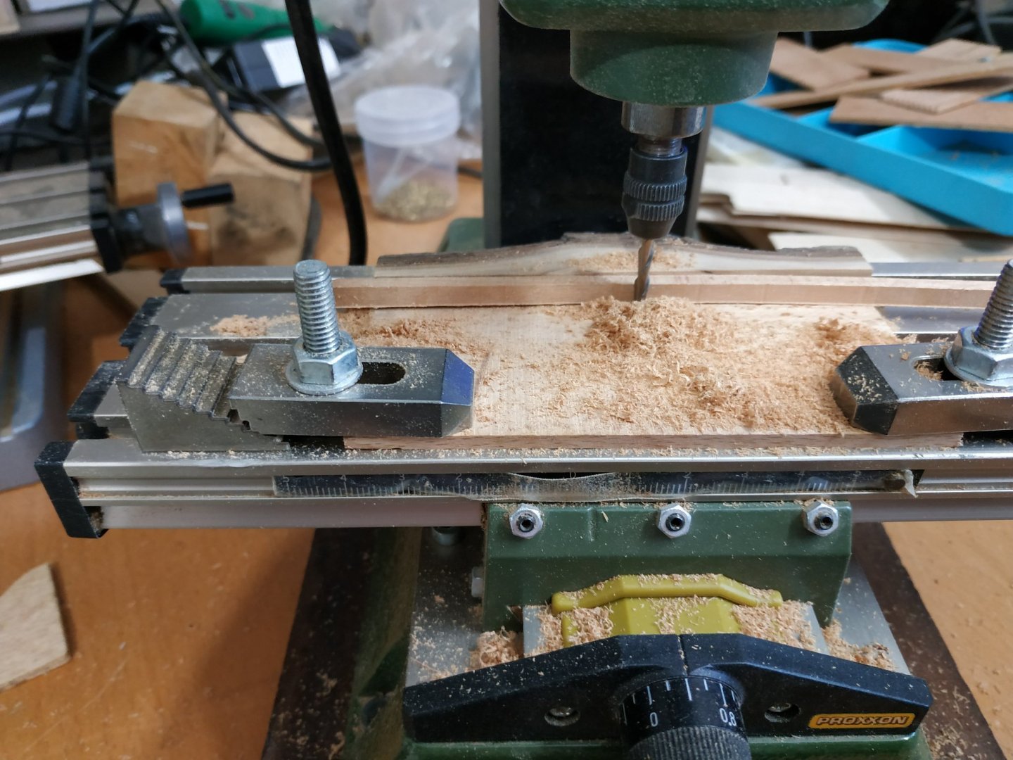
Hi. In one of your recent videos , you used a tilting table for the sherline mill. Do you happen to know if this can be adapted for use with the simple X-Y table that is part of my Proxxon M70. (I'd love a shireline but I still love my wife- difficult choice, but the shireline, while versatile, can't cook and kiss me goodnight)
-
Swan-Class Sloop by Stuglo - FINISHED - 1:48
stuglo replied to stuglo's topic in - Build logs for subjects built 1751 - 1800
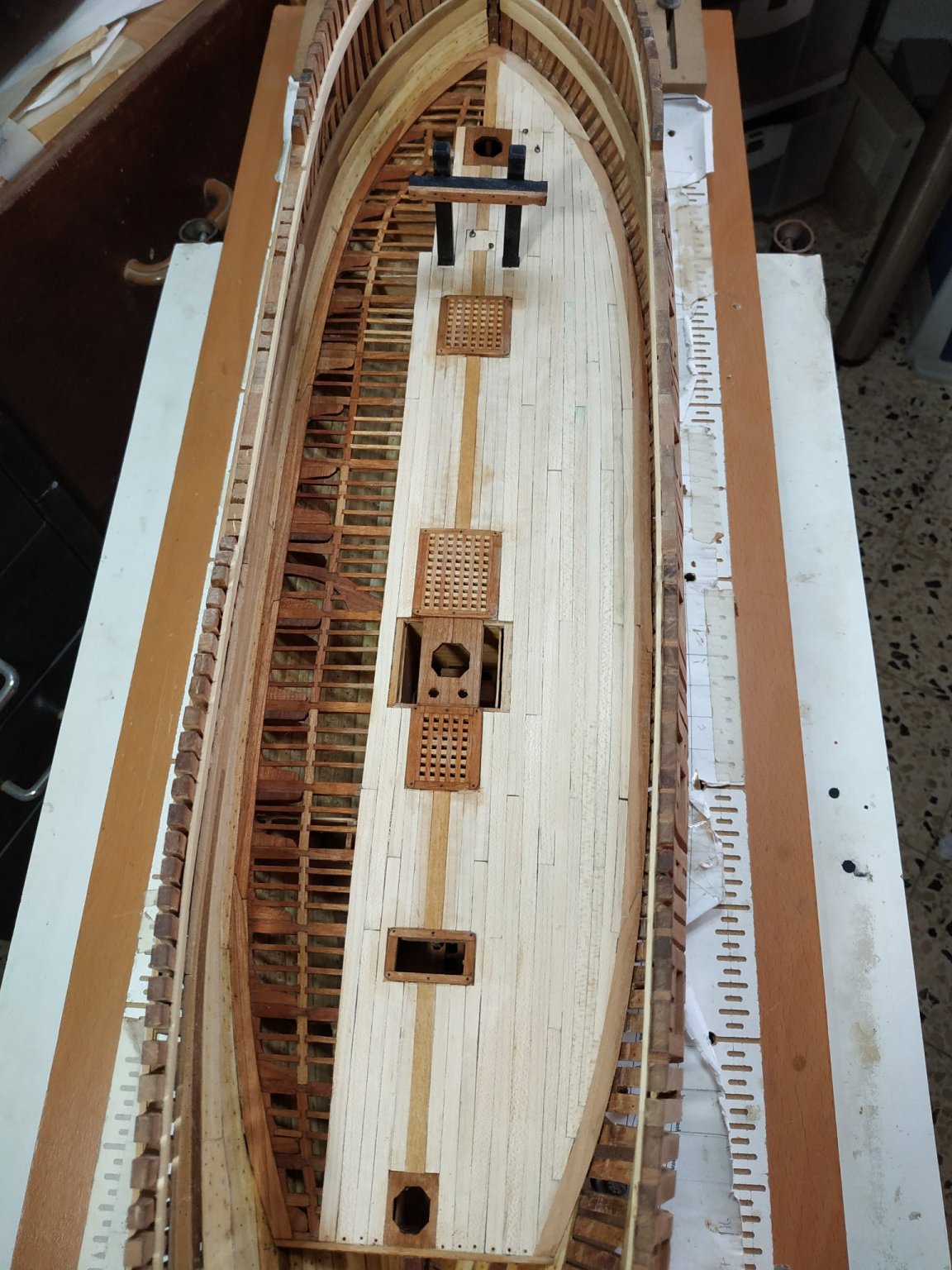
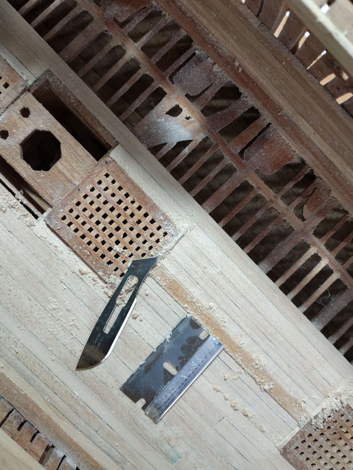
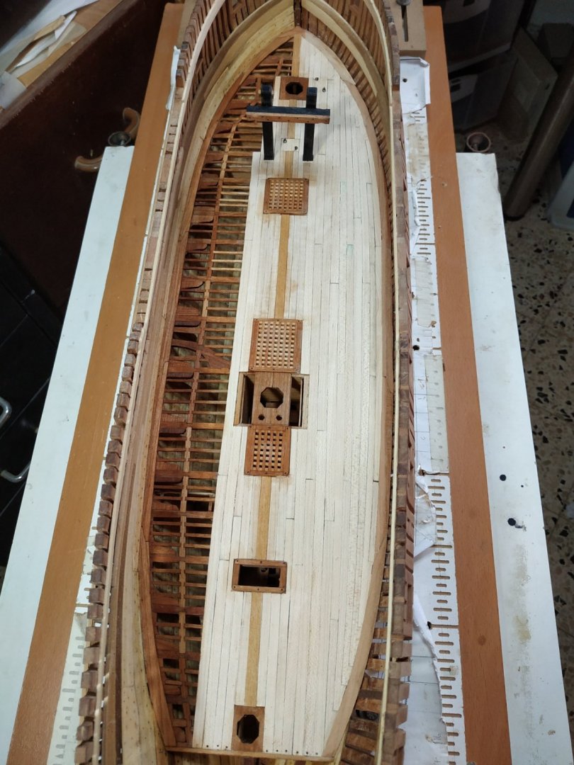
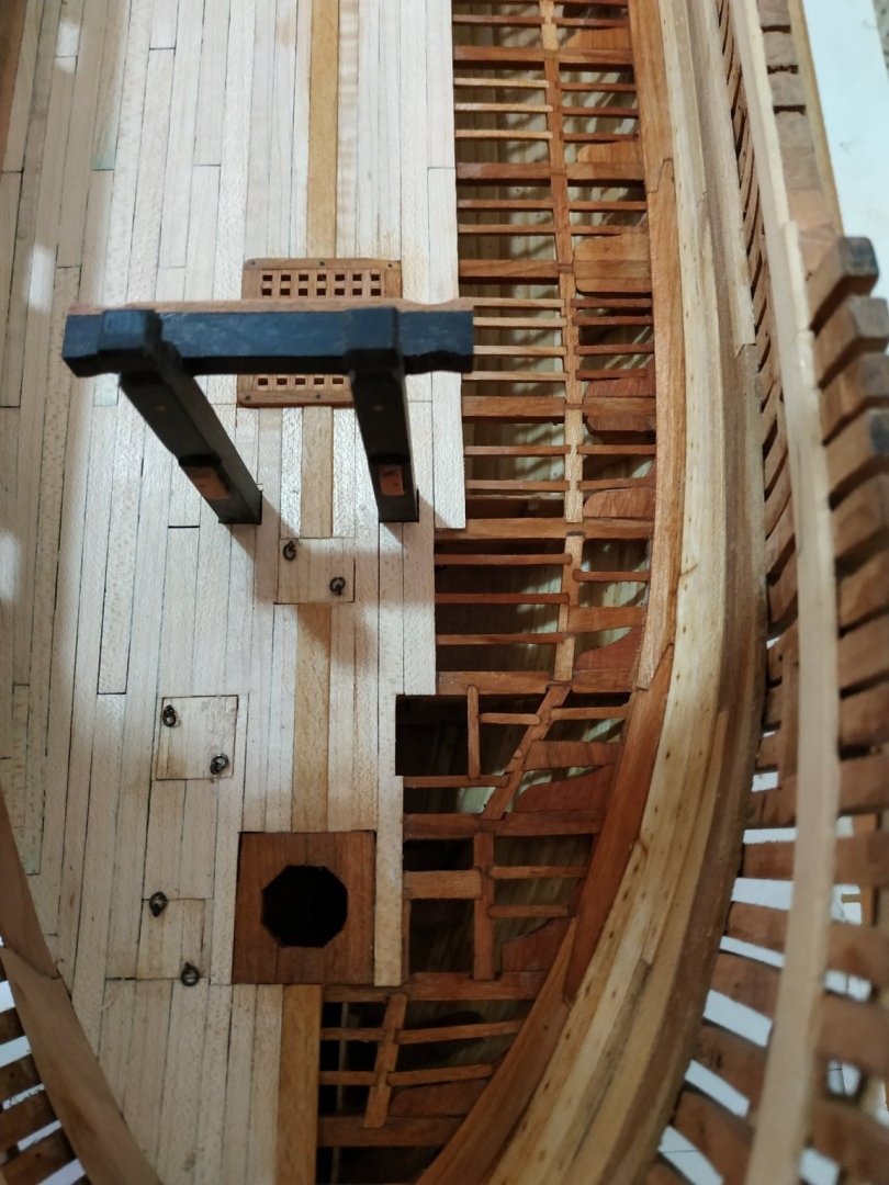
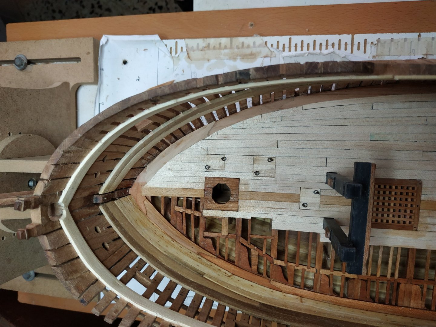
Lower Deck -cont. Reading again ahead, finish and fit the Riding Bitts. Add the Backing Piece of contrasting colour wood(was elm) 10.6x3.45 and 2.12 mm thick. Also using the same wood, wedge shaped cleats which add support for the upper deck beam. Planking the Lower Deck- Beech wood Ignoring the Let Down, the planks are 1.0mm thickness.I made them at 1.20mm to allow for “levelling”. The first to be fitted are the Binding Strikes- a pair either side of the comings. These are 5.3mm wide, tapering fore and aft- staggered 4 plank shift. As a first for me, I marked the edges and ends with pencil to enhance the joint lines. The spaces between the Binding Strakes and the Central Plank are “shut in” Outside of the Binding Strakes, 5 narrower planks (4.75mm)with more marked tapering . The next few planks (working outwards) would, if worked normally, would have ends that would be too narrow. These ends are modified so the plank is “Dropped” ( I drop things all the time but don’t have a special name- except “clumsy bugger”) A plank, about a 1/3rd wider, is used, so that a barb-like end is formed (like a harpoon), so that the end of the neighbouring plank fits into the notch. Decided for now to leave most of the port side unplanked-the rooms and bulkheads beneath are invisible, but the deck structures look good. Finishing the planking-levelling and smoothing including the inner aspect of the waterway to match the plank height. ( I used sandpaper, single edge razor and larger, curved scalpel blades-see posts related to these subjects)


-
Never had this problem. I use the kitchen variety on harder woods such of walnut. Even against the skin it doesn't scratch. Of course, the wood is already smooth and minimal pressure is applied.
-
On larger surfaces, such as hulls and decks, I apply tung oil with the steel wool, and then wipe off any excess.
-
Single edge razor blade or 22/24 scalpel blades
-
Never heard of ABS before. If you mention this I assume you know this is the stuff used in the kit. ? similar to plexiglass, which I "glue" with chloroform?
-
Swan-Class Sloop by Stuglo - FINISHED - 1:48
stuglo replied to stuglo's topic in - Build logs for subjects built 1751 - 1800
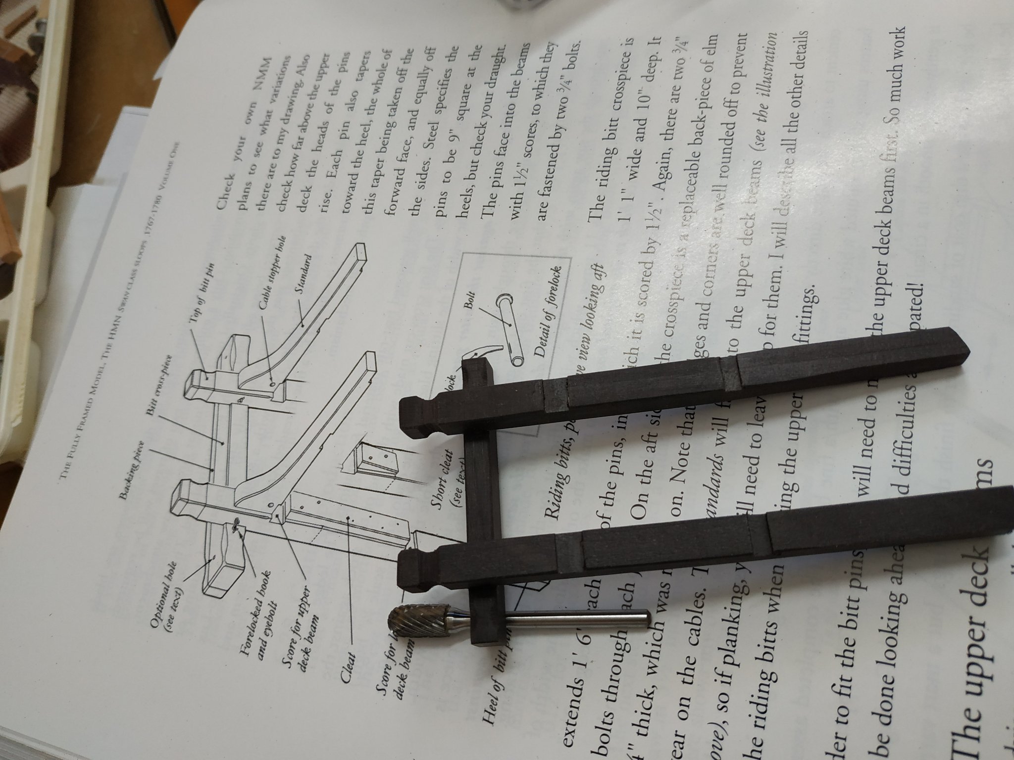
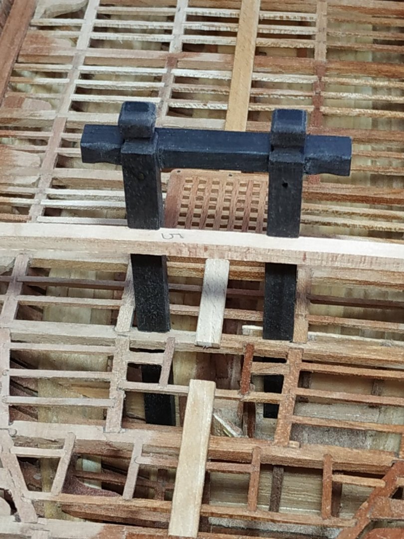
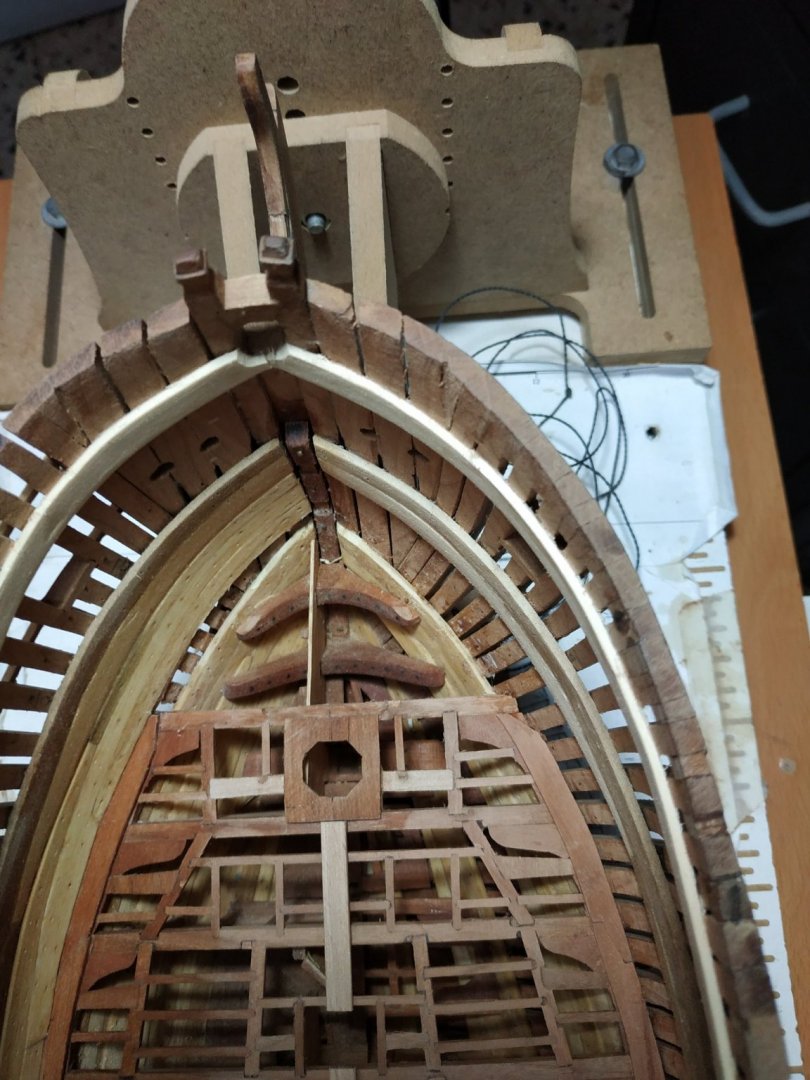
Riding Bitts The Pins of these have previously been made-they support the aft aspect of #5 lower deck beam. They are repositioned, and checked to see if they are perpendicular. Slightly out, the scoring depth increased from 0.8mm to 1mm, did the job. The #5 upper deck beam is positioned and its height is checked using the profile plan. In this case, resting,without letting down,gave the desired result. This is marked against the Pins, and the scoring of 0.8mm is made using the milling machine. The cross piece is now to be made.-6.89mm x 5.3mm of length 56.85mm. The head is grooved with the shaped milling piece and the edges chamfered. (except aft - another piece will be added later). Height (position) on the Pins is marked and again scored to 0.8mm. The cross piece is fixed to the Pins, allowing 23.85 space between them,and the edges of the fore aspect chamfered - the more so the edges of the extensions outside of the Pins. (I’ll leave it off the model until most of the deck is completed)
-
Swan-Class Sloop by Stuglo - FINISHED - 1:48
stuglo replied to stuglo's topic in - Build logs for subjects built 1751 - 1800
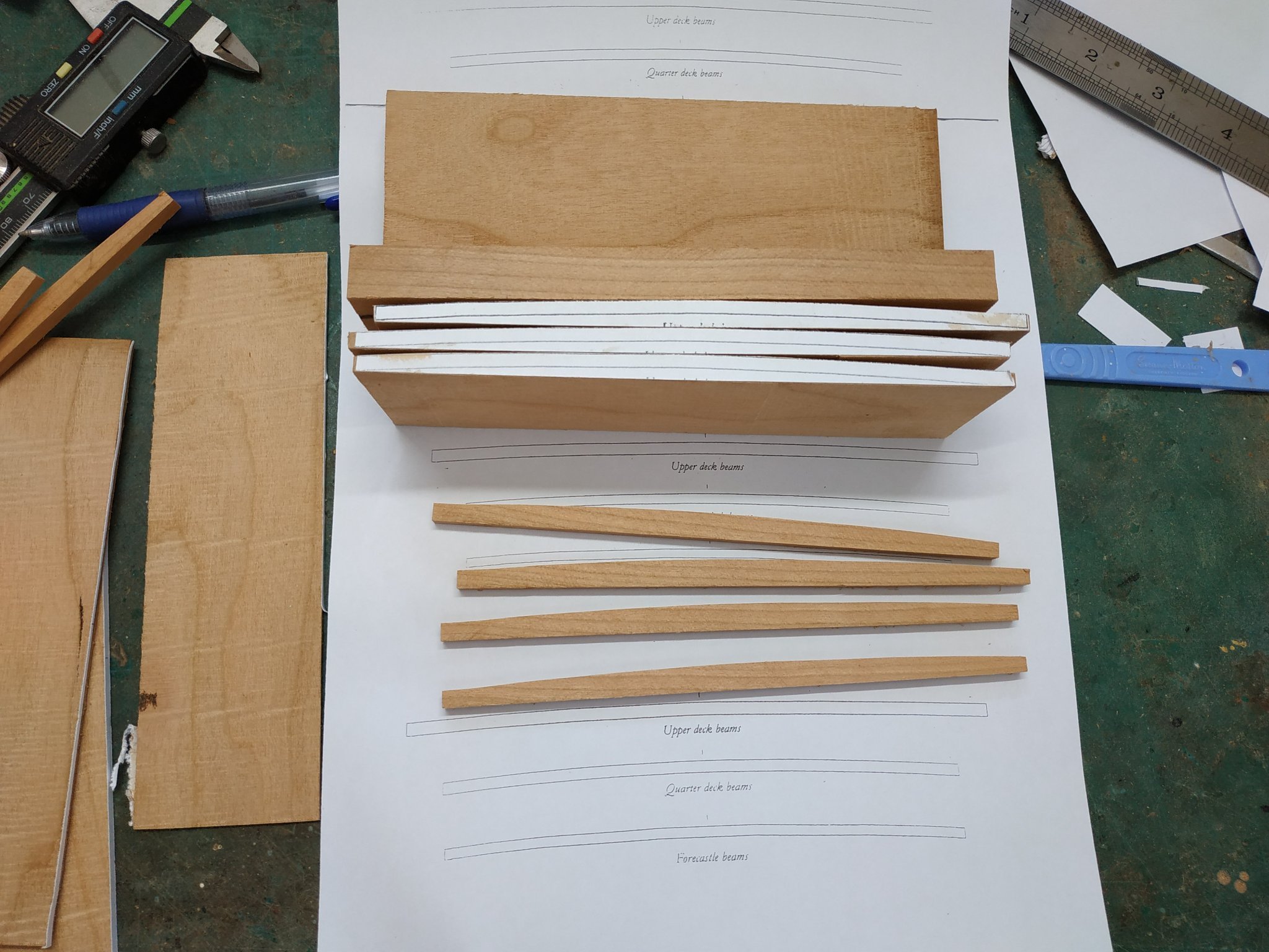
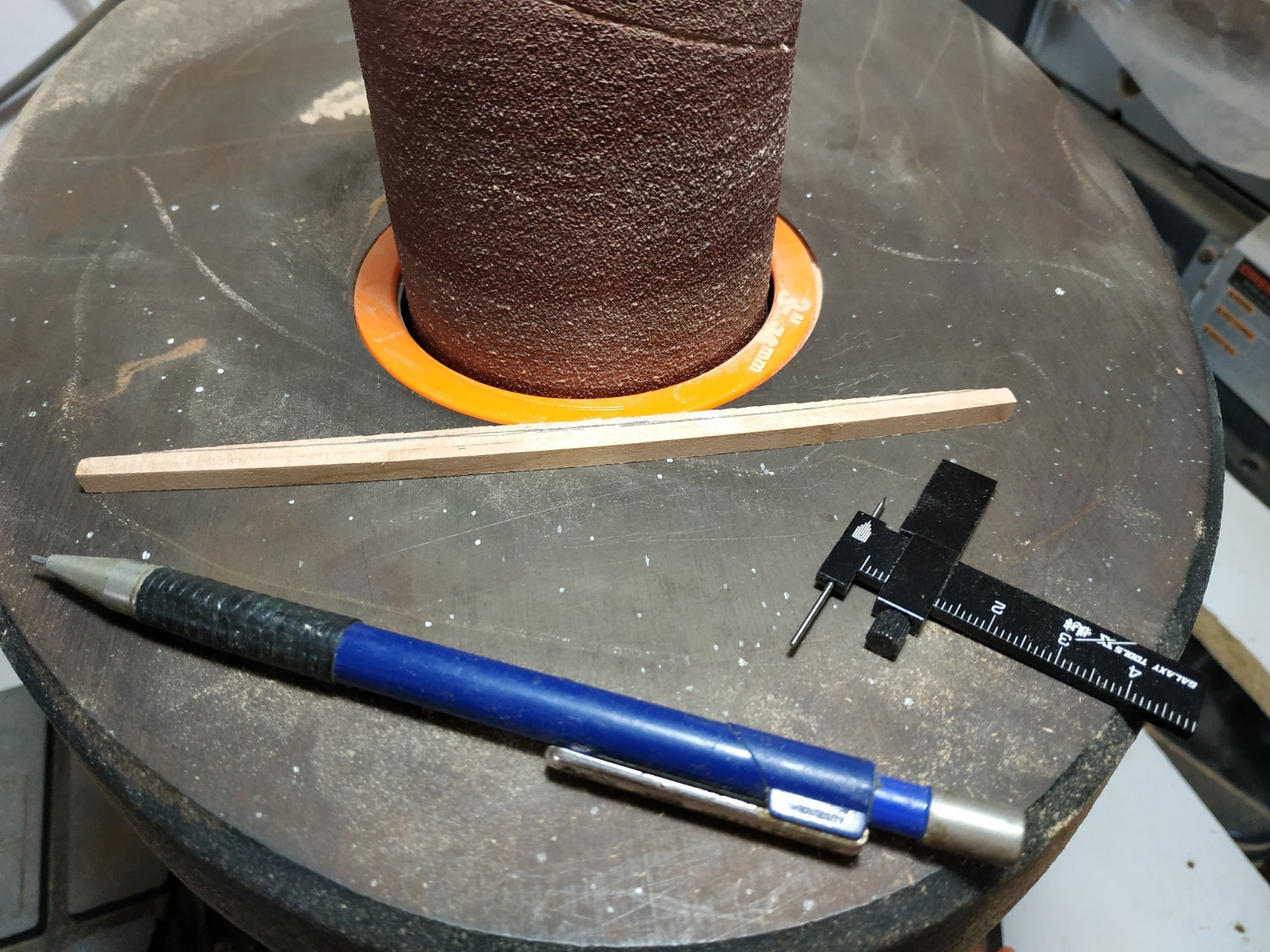
Lower Deck Planking-cont. In fact, before continuing, suggested making the Riding Bitts. The PINS for this were made,so to fit location aft of #5 beam, where it is scored so as to support said beam. These Pins must be scored to fit the UPPER deck beams-Which therefore have to be made first and appropriately positioned. My bible, T(testament)FFM, refers me back to section 5.10 “as you did the lower deck”. Luckily, I checked with ch. 8.4 (vol. 2 -Deuteronomy) where I found that the upper beam deck size is given as 4.77mm X 3.71mm and some words as to whether to let down onto the clamps or not. (Changes in instructions are also known when repeated in the other Bible). 22 beams are required. Having tried various ways previously, I used the following method. 4 blocks, 16.5cm length, 5cmdeep and 1.0cm wide. (Thinner difficult to keep at 90deg) Cut out pattern both sides of width. Convex side, formed with spindle sander-flipping over frequently to ensure equal 90deg (same effect) 4.77mm slices with the table saw Inscribe parallel line to form the concave surface( a little wider than the 3.71mm) Finish more accurately with several passes between the milling drill bit and a fixed resistance. The gap narrows progressively until the required thickness is obtained. The beam passing by the bit, needs stabilizing as it passes the bit (I use a finger) This way I only ruined 20% !!!!

-
Swan-Class Sloop by Stuglo - FINISHED - 1:48
stuglo replied to stuglo's topic in - Build logs for subjects built 1751 - 1800
a proxxon- blades on a rotating wheal- an electric plane. -
Swan-Class Sloop by Stuglo - FINISHED - 1:48
stuglo replied to stuglo's topic in - Build logs for subjects built 1751 - 1800
tried but the proxxon (mine at least) is unforgiving and tends to chew up v. thin or shorter pieces. Possible the blade settings, but have,'t yet the courage to play with them. For small pieces, I use a milling machine. -
Swan-Class Sloop by Stuglo - FINISHED - 1:48
stuglo replied to stuglo's topic in - Build logs for subjects built 1751 - 1800
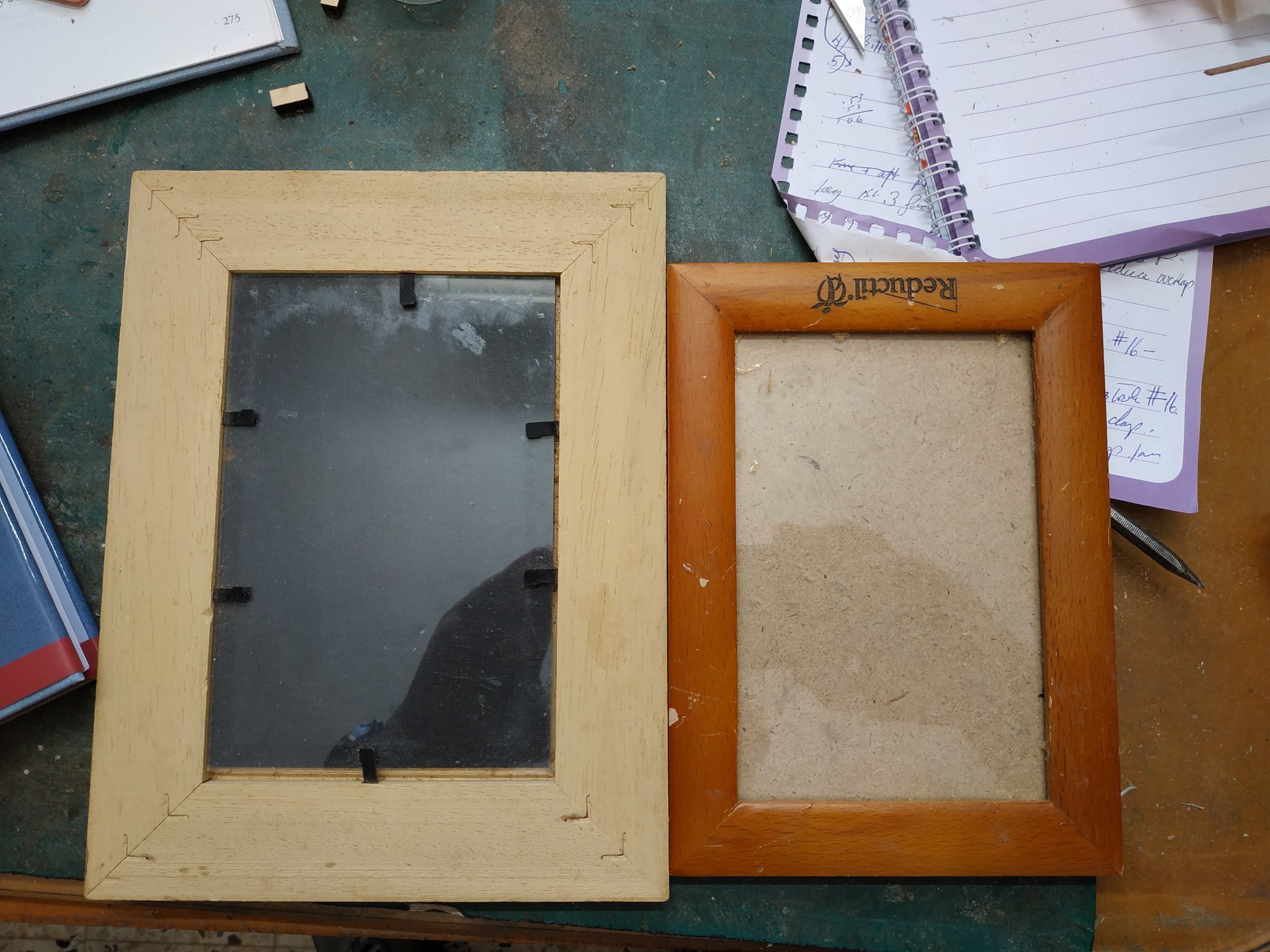
Kevin, Another Idea that I meant to pass on when I saw the gluing of right-angled parts, for which you use clamps and jig on glass. Try an old photo frame. The angle and glass always there. Also I can place pattern under the glass and stick bits into position without them sticking to the plan.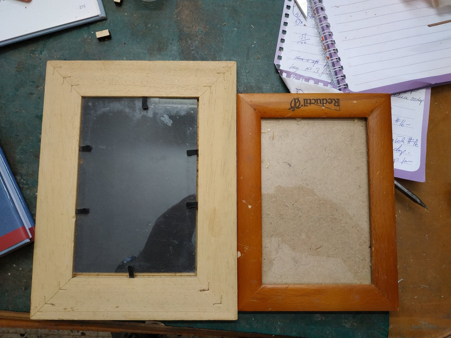
-
Swan-Class Sloop by Stuglo - FINISHED - 1:48
stuglo replied to stuglo's topic in - Build logs for subjects built 1751 - 1800
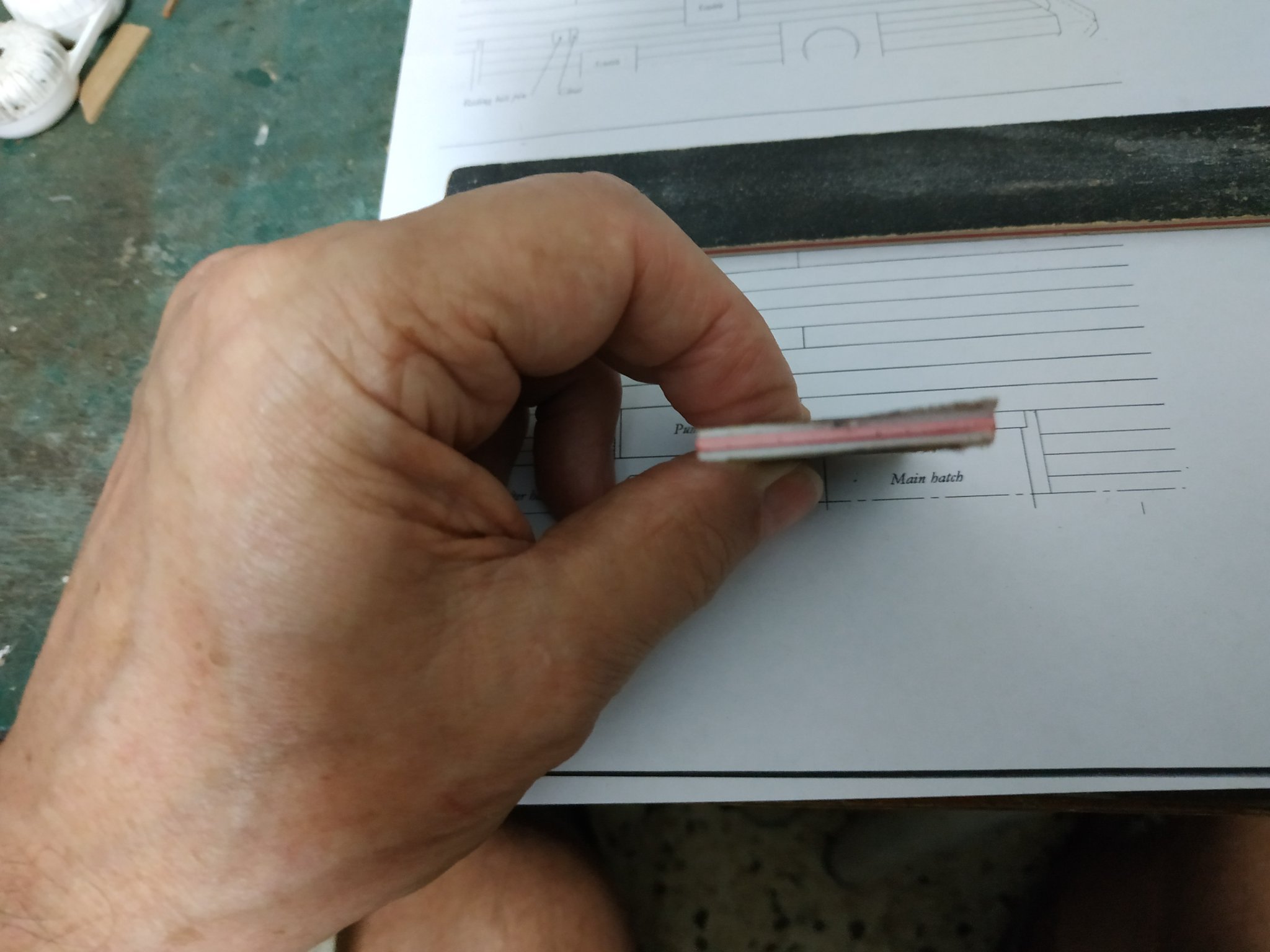
try this out. I took an already well-used emory board (less abrasive) of softer sandwich type. Cut a 3mm rim of the sand paper layer away. The edges are soft and non-damaging to the wood you wish to be un-effected. (the already-rounded corner is a useful bonus)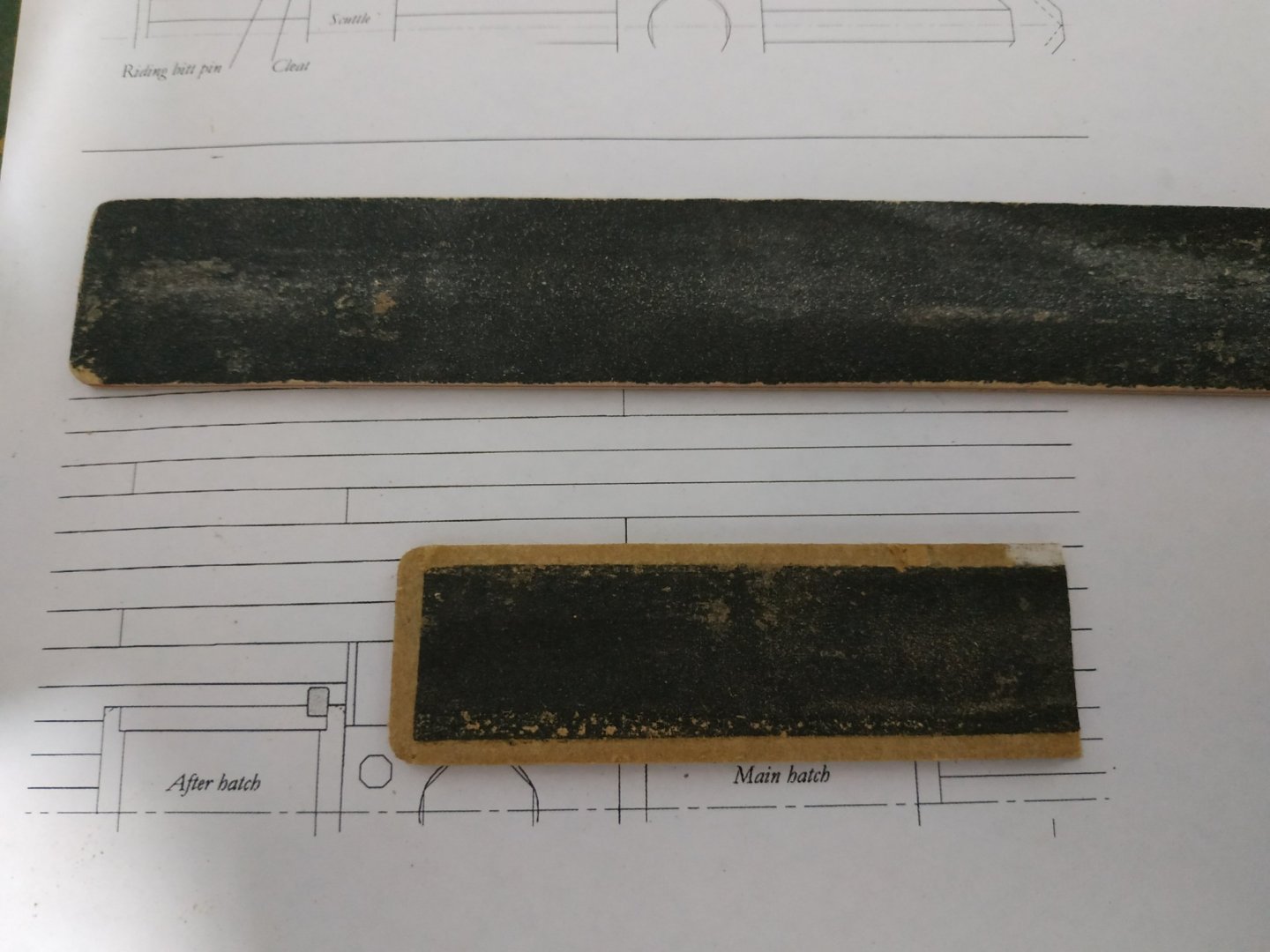

-
Swan-Class Sloop by Stuglo - FINISHED - 1:48
stuglo replied to stuglo's topic in - Build logs for subjects built 1751 - 1800
Correct. Then I have to remember-so I write notes. Then I have to remember to read the notes-so I try and read my scribble. Life is complicated -
Swan-Class Sloop by Stuglo - FINISHED - 1:48
stuglo replied to stuglo's topic in - Build logs for subjects built 1751 - 1800
Intend to do so after I fit other planks. These will need sanding and my initial intension is to sand the outer waterway to match their level -
Swan-Class Sloop by Stuglo - FINISHED - 1:48
stuglo replied to stuglo's topic in - Build logs for subjects built 1751 - 1800
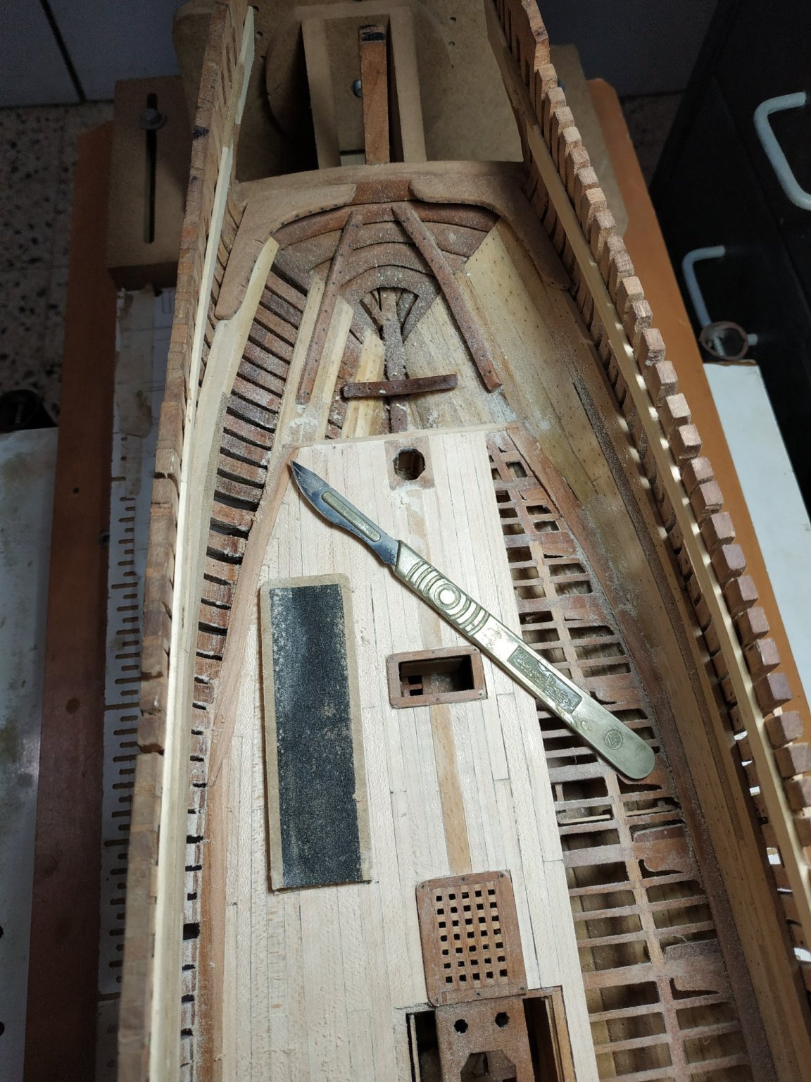
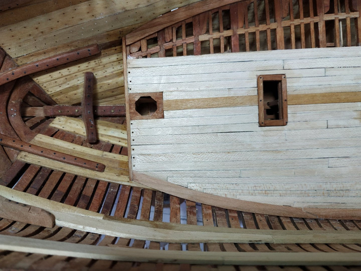
Return to Deck Hook and Eking Piece. When placing the foremost part of the central plank I realised I had made a fundamental error. In forgetting the TFFM instruction, I made the Eking piece stand proud of the beam,by dropping the beam, so that the waterway plank ended flush with this. So the front end of the deck needed unsticking. It and #1and #2 beams,the foremost waterway planks remade, and a new central piece joining the to the stemson, so they overlay the Deck Hook. ( As Miss Piggy would say “ attacked by DUMMO rays”)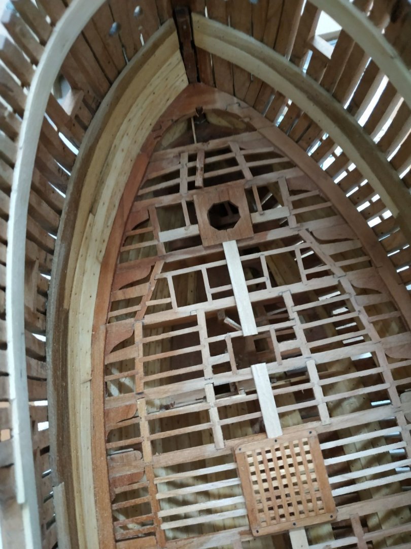
-
Interested in treenail cutter. Will pay extra postage to overseas but have US address if not possible
-
Jumping way ahead , what glue do you recommend for the plastic to plastic parts? It's been 30 years since I built a plastic kit.
-
Received email from Cornwell saying parts ordered. Good polite service.
-
Hi Ted 99 The fittings were in a small box with the rigging cords and copper nails etc.. The Large view is mentioned above the 6 plans. UPS express saver- but the company here takes advantage as price only quoted after arrives at local customs. (Called customs, as it is the custom to screw us, the private buyers.)
-
"I am missing one package of small plastic detail parts-- "vents"." I'd better check my plastic bits as well. "Total shipped to the USA was 456.83 GBP" lucky you -my shipping was 115GBP ( the distance is 20% LESS) + 140 GBP tax + 80GBP local handling charge. But I still think worth it . My enthusiasm somewhat waned when I saw missing and damaged pieces, but is reviving when I see my kids and grandkids fighting over who will get the finished model.
-
Swan-Class Sloop by Stuglo - FINISHED - 1:48
stuglo replied to stuglo's topic in - Build logs for subjects built 1751 - 1800
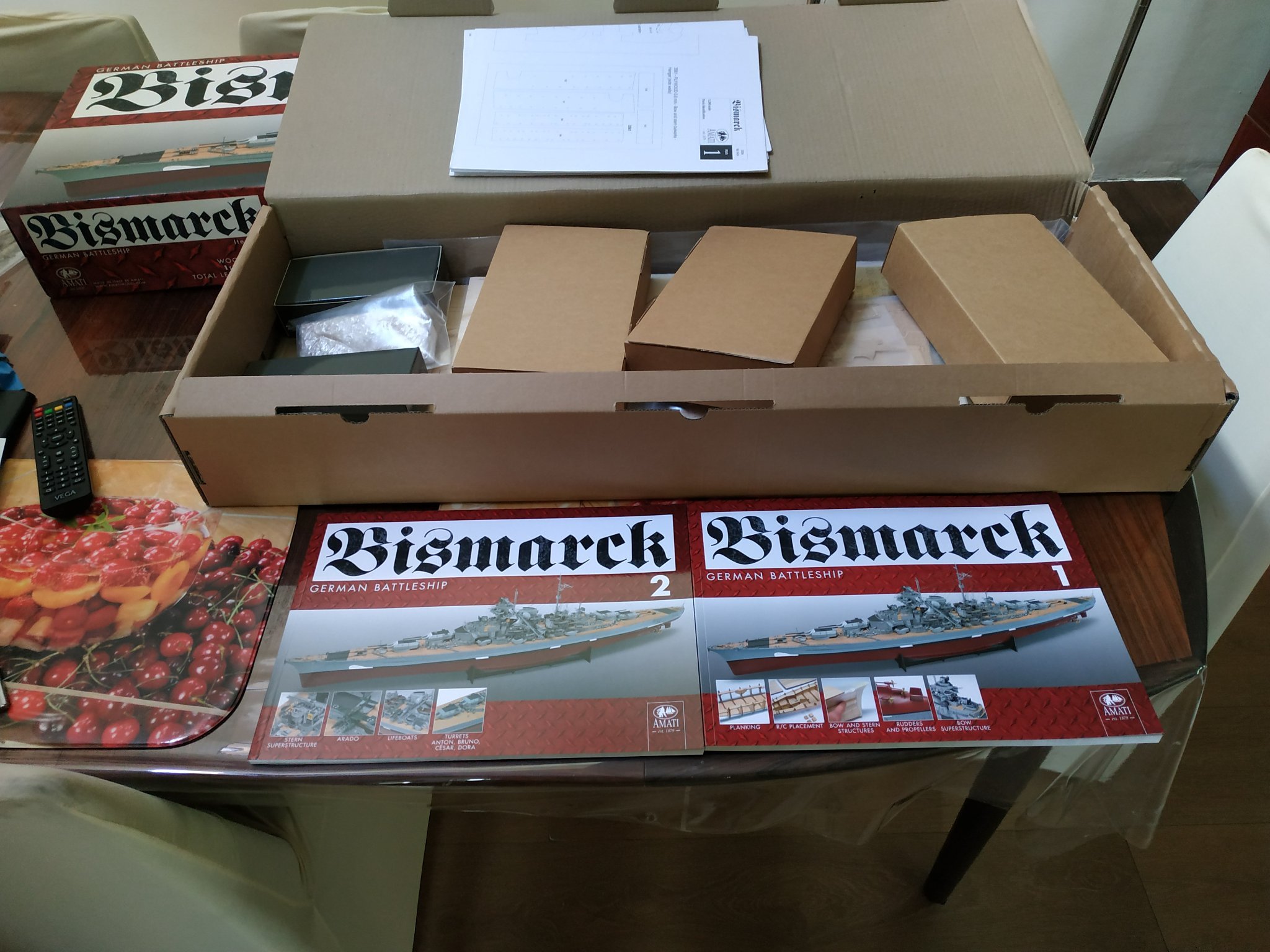
FOR WHEN I FINISH THE SWAN OR NEED A DIVERTION Just Delivered (not by a Stork- a WW2 German plane) Almost healthy girl (ships are "she") weighing in at 9kilo and expected to grow to 127cms Thanks to advice to check and notify, found some metal bits missing, as was the printed large view. Also. the contents were loosely packed and the ends of the printed bow pieces damaged-replacements requested. Amati is a long established company and they should employ an English-speaking proof reader. The outside of the box states that the Bismarck was the PROUD (sic) of the navy..... and the MITH (sic) began. Not in the mood to check the TWO books of illustrated instructions

-
Just Delivered (not by a Stork- a WW2 German plane) Almost healthy girl (ships are "she") weighing in at 9kilo and expected to grow to 127cms Thanks to above advice to check and notify, found some metal bits missing, as was the printed large view. Also. the contents were loosely packed and the ends of the printed bow pieces damaged-replacements requested. Amati is a long established company and they should employ an English-speaking proof reader. The outside of the box states that the Bismarck was the PROUD (sic) of the navy..... and the MITH (sic) began. Not in the mood to check the TWO books of illustrated instructions


-
Swan-Class Sloop by Stuglo - FINISHED - 1:48
stuglo replied to stuglo's topic in - Build logs for subjects built 1751 - 1800
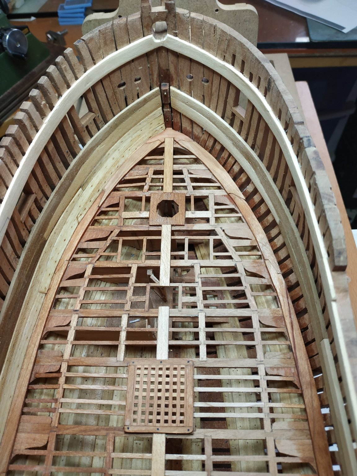
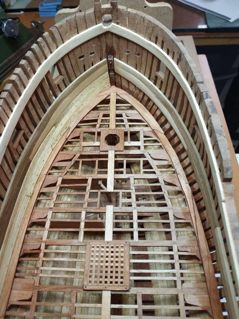
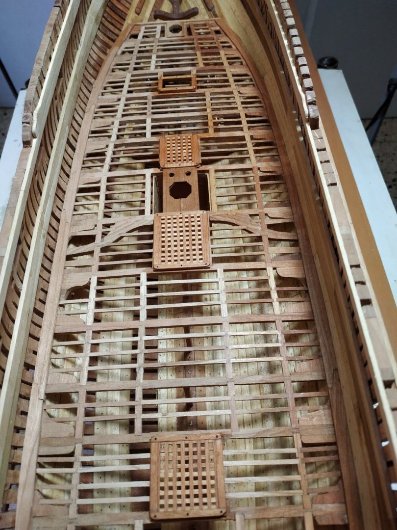
Hatch Coamings. Framework around the gratings and ladder opening. The aft/forward (also called coamings) are 3.18mm x 2.65mm (deep) Athwartship, head-ledges, are 2.65mm. The corner joints are a fancy half lap, said to be sloped or angled-this extra feature beyond me. In order to see the joint-line, the upper piece is simply made thinner.(1.25/1.40). The upper part of the joint, seen above the planks, is rounded off. A small jig with a right-angle of a plank to be used, served to “blank off” the lower part that will remain square after sanding this rounding(also called radialising). The grating should be thinned to reach the appropriate thickness. I used the milling machine as my attempts with a sanding board resulted in unwanted curving. Black wood treenails represent bolts placed at joints and the center of the frame. (Although I used different woods for the frame and gratings, when oiled, this is difficult to see. Different choice for other decks.)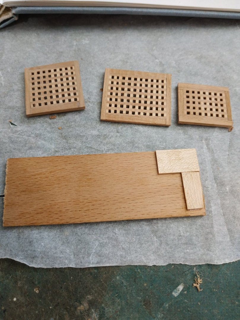
-
"I have never seen the Trumpeter plastic kit, but from pictures, it looks as though it could be similar to this Amati kit if you add the super detail" -is the additional detail referred to the Trumpeter or Amati kit ?